1
22-812.fm Page 1 Monday, April 8, 2002 1:32 PM
68/4CPIG"&KIKVCN"/WNVKOGVGT
YKVJ"2%"+PVGTHCEG
22-812
Auto-Ranging with Manual-Ranging Override —
automatically selects a range when you measure
voltage, current, resistance, capacitance, and
frequency. You can also manually set the range
when measuring values you know are within a
certain range.
Computer Interface with Supplied Software —
you can connect the meter to your computer and
use the supplied software to log and graph
measurements.
Logic Function — you can use the meter to test
HI and LO logic levels.
Multiple Displays — the supplied software
displays the information you see on your meter’s
display onto your computer’s monitor, updating it
4 times per second.
Automatic Data Logging — the software works
with your meter and computer to select the
correct sampling rate for your application, then
capture and store data. The software logs the
time for each reading, helping you keep track of
each sample. You can also save logged data in
your hard drive for future reference.
#
#
"+/2146#06"
If an icon appears at the end of a paragraph, go to the box on that page with the corresponding icon
for pertinent information.
Rý— Warning
# — Important
. — Caution
° — Hint
± — Note
OWNER’S MANUAL
Please read before using this equipment.
© 2002 RadioShack Corporation.
All Rights Reserved.
RadioShack and RadioShack.com are trademarks used by
RadioShack Corporation.
22-812.fm Page 2 Monday, April 8, 2002 1:32 PM
#"+/2146#06"#
System Requirements
Completely read this
manual before you use this
meter.
%106'065
System Requirements ..... 2
A Word About Safety ....... 2
Special Panel Markings 4
Specifications .................. 5
A Quick Look at
Your Meter ....................... 9
Preparation .................... 11
Installing a Battery ...... 11
Connecting the
Test Leads .................. 11
Using the Stand .......... 12
Using the
Rubber Boot ............... 12
Using the Meter ............. 12
Turning the Meter
On/Off/Testing the
Display ........................ 12
Before You Start ......... 13
Holding a
Measurement ............. 15
Using Relative
Measurement ............. 15
Automatic Power Off ... 16
Using Monitor ............. 17
Making Measurements .. 18
Measuring DC Voltage 18
Displaying
Temperature ............... 19
Measuring AC Voltage 19
Measuring DC/AC
Current ....................... 20
Measuring
Resistance .................. 21
Measuring
Capacitance ............... 23
(continued)
2
Your RadioShack 46-Range Digital Multimeter is a
portable, compact, auto-ranging, digital multimeter.
It is ideally suited for field, lab, shop, and home
applications. The multimeter provides precise
measurements and is built to provide the highest
possible reliability. The meter measures voltage up
to 1000V DC and 750V AC, DC and AC current up
to 10A, resistance up to 40MΩ, capacitance from
0.5nF to 40µF, and frequency from 10Hz to 4MHz.
Its 33/4-digit digital display can display up to 4,000
units. #"±
5;56'/"4'37+4'/'065
You can use your meter either with or without a
computer. Before connecting the meter to your
computer, be sure it is an IBM PC with a Pentium
133 MHz processor or compatible, running
Windows 95, Windows 98, Windows ME, Windows
2000, or Windows XP, with all of the following: ±
• VGA or SVGA video adapter
• at least 32 MB RAM
• Microsoft-compatible mouse
You cannot use the meter with Microsoft Windows
3.1.
Your multimeter requires one 9V battery (not
supplied).
#"914&"#$176"5#('6;
We have taken every precaution in designing this
meter to ensure that it is as safe as we can make it.
But safe operation depends on you, the operator.
We recommend that you follow these simple safety
rules:
• Never apply voltages to the meter that exceed
the limits given in the specifications. Never
22-812.fm Page 3 Monday, April 8, 2002 1:32 PM
• Use extreme caution when working with
voltages above 100V. Always disconnect
power from the circuit you are measuring
before you connect test leads to high-voltage
points.
• Never connect the test leads to a voltage
source when you set the meter’s function
selector to –/„, •, LOGIC/Hz, / µA/A, or
/ mA/A.
• Always discharge any capacitors of the circuit
under test before you attach test leads.
• Always turn off power and disconnect the test
leads from the circuit you are testing before you
replace the meter’s battery or fuse.
(continued)
Checking Continuity ... 23
Checking Diodes ........ 24
Measuring Logic ......... 25
Measuring
Frequency/
Duty Cycle/
Pulse Width ................ 25
Measuring hFE ........... 27
Using the Meter
With a Computer ............ 28
Installing the Meter’s
Software/Hardware ..... 28
Configuring/Using the
Meter and Software .... 29
Care and Maintenance .. 30
Cleaning ..................... 30
Replacing the Fuses ... 30
• Never operate the meter unless its back cover
and battery cover are in place and fully closed.
• This equipment is rated for installation category
II (maximum 3600VA).
ý
•
• Because many AC/DC sets have a potentially
hot chassis, be sure the top of your workbench
and the floor underneath it are made of nonconductive materials.
This meter is fully calibrated and tested. Under
normal use, no further adjustment should be
necessary except as noted in this Owner’s Manual.
If the meter requires repair, do not try to adjust it
yourself. Take it to your local RadioShack store.
Rý
R
R
"9#40+0)ý
"
Use extreme caution in
the use of this device.
improper use of this
device can result in
injury or death. Follow all
safeguards suggested in
this owner’s manual, in
addition to normal safety
precautions, in dealing
with electrical circuits.
Do not use this device if
you are unfamiliar with
electrical circuits and
testing procedures.
•
Never try to probe with
both test leads at the
same time or hold both
test leads in one hand.
(continued)
3
A Word About Safety
apply more than 1000V DC or 750V RMS AC
between the input jacks and ground.
22-812.fm Page 4 Monday, April 8, 2002 1:32 PM
ý
R
"9#40+0)ý
(continued)
•
A Word About Safety
•
•
R
"
Use extreme care while
using the meter to measure current and voltage
in commercial electrical
panels. Unlike a home
AC outlet, a commercial
electrical panel has tremendous current surge
potential. This is
especially true for threephase industrial
electrical panels. A small
spark from one of these
panels can cause a
plasma explosion and
fire that can severely
burn you. Do not hold the
meter while using it.
Always wear protective
leather gloves, a face
shield, and fireproof arm
and upper body
protection while using
the meter to measure
current and voltage in
commercial electrical
panels.
If this equipment is used
in a manner not specified
by the manufacturer, the
protection provided by
the equipment may be
impaired.
•
To reduce the risk of fire
or shock hazard, do not
expose this product to
rain or moisture.
•
For indoor use only.
4
52'%+#."2#0'."/#4-+0)5
For your safety, we have added special markings to
the meter’s panel to remind you of the
measurement limitations.
The maximum voltage that this meter can
measure is 1000V DC or 750V AC. The
maximum current that this terminal can
measure is 400mA DC and AC.
Caution: Be extremely careful when
making high-voltage measurements; DO
NOT TOUCH TERMINALS OR PROBE
ENDS.
!
Caution: Risk of electric shock! Refer to
the complete operating instructions.
The meter is protected by double
insulation.
CAT II
This equipment is rated for
INSTALLATION CATEGORY II (3600VA
max.).
To avoid electrical shock or instrument
damage, do not connect the common input
terminal (– COM jack) to any source that
exceeds 500 volts with respect to earth/
ground.
The maximum current you can measure at
+10A MAX
this jack is 10 amps DC/AC. This jack is
FUSED
fuse-protected.
WARNING:
Shock
The sliding guard on the front of the meter
Hazard if protects against electrical shock. Do not
guard not remove the guard.
installed.
22-812.fm Page 5 Monday, April 8, 2002 1:32 PM
52'%+(+%#6+105
Accuracies at 73.4°F (23°C) ±5°, <75% RH
DC VOLTS (Maximum Measurement: 1000V)
400mV ............................................... ± 0.3% of Reading,
± 4 in Last Digit
4V to 40V ........................................... ± 0.3% of Reading,
± 3 in Last Digit
400V .................................................. ± 0.5% of Reading,
± 3 in Last Digit
1000V ................................................ ± 0.5% of Reading,
± 4 in Last Digit
AC VOLTS (Maximum Measurement: 750Vrms at 50/60
Hz, Average Responds, RMS Calibrated, AC Coupled)
400mV ................................................ ± 0.5% of Reading,
± 4 in Last Digit
4V to 40V ........................................... ± 0.5% of Reading,
± 3 in Last Digit
400V .................................................. ± 0.6% of Reading,
± 3 in Last Digit
750V .................................................. ± 0.8% of Reading,
± 4 in Last Digit
Specifications
dBm ACCURACY (–31.8dBm to +59.7dBm at 50/60 Hz
sine wave) ......................................................... ± 0.3dBm,
± 2 in Last Digit
DC CURRENT (Maximum Measurement: 10A)
400µA ................................................ ± 0.8% of Reading,
± 5 in Last Digit
4mA ................................................... ± 0.6% of Reading,
± 3 in Last Digit
40mA ................................................. ± 0.8% of Reading,
± 5 in Last Digit
400mA ............................................... ± 0.6% of Reading,
± 3 in Last Digit
4A ...................................................... ± 0.8% of Reading,
± 5 in Last Digit
10A .................................................... ± 1.0% of Reading,
± 5 in Last Digit
5
22-812.fm Page 6 Monday, April 8, 2002 1:32 PM
AC CURRENT (Average Responds, RMS Calibrated, 10A
Maximum, DC Coupled)
400µA ................................................ ± 1.0% of Reading,
± 5 in Last Digit
4mA ................................................... ± 0.8% of Reading,
± 3 in Last Digit
40mA ................................................. ± 1.0% of Reading,
± 5 in Last Digit
400mA ............................................... ± 0.8% of Reading,
± 3 in Last Digit
4A ...................................................... ± 1.0% of Reading,
± 5 in Last Digit
10A .................................................... ± 1.2% of Reading,
± 5 in Last Digit
RESISTANCE
400Ω ................................................. ± 0.4% of Reading,
± 5 in Last Digit
4kΩ – 40kΩ– 400kΩ .......................... ± 0.3% of Reading,
± 3 in Last Digit
4.0MΩ ................................................ ± 0.6% of Reading,
± 3 in Last Digit
40MΩ ................................................ ± 1.5% of Reading,
± 5 in Last Digit
CAPACITANCE
Specifications
4nF .................................................... ± 3.0% of Reading,
± 40 in Last Digits
±"016'"±"
Accuracy with film capacitor
or better, specified from
9.5% of full scale to full
scale except 4.0nF range
from 0.5nF to full scale.
40nF .................................................. ± 3.0% of Reading,
± 10 in Last Digits
400nF – 4µF – 40µF ......................... ± 2.0% of Reading,
± 4 in Last Digit ±
PULSE WIDTHS (Frequency Range: 10Hz to 100kHz)
1µS to 90mS (at +5/–0V square wave):
.............................................................. ± 5% of Reading,
±2 in Last Digit
K-TEMPERATURE MODE
This is a special voltage mode, to be used with an optional
thermocouple module that can be attached to the meter.
This mode automatically converts the 1mV per °C or °F
voltage into a readout that appears as a temperature. In
these modes, the unit can show up to ± 999°C or °F.
6
22-812.fm Page 7 Monday, April 8, 2002 1:32 PM
The accuracy of these modes is determined by the external device and the accuracy of the DC volt mode. The
temperature range of the newer 1mV per degree C
probes are generally between –50°C and 1000°C.
FREQUENCY
Accuracy
400Hz – 4k–40k–400kHz–4MHz:
.................................. ± 0.1% of Reading, ± 4 in Last Digit
Sensitivity
The function selector set to LOGIC/Hz (10Hz – 4MHz)
400Hz–4k–40kHz ............................................ 50 mVrms
400kHz ........................................................... 100 mVrms
4MHz ............................................................. 250 mVrms
For AC voltage frequency, the function selector set to
°C/°F /
V (maximum measuring frequency 1 kHz for
signal above 40V)
10Hz to 1 kHz .................................................. 70 mVrms
1kHz to 10 kHz .............................................. 400 mVrms
For AC voltage frequency, the function selector set to
dBm ~ V (maximum measuring frequency 1 kHz for signal
above 40V)
10 Hz to 200 Hz ............................................. 300 mVrms
200 Hz to 1 kHz ................................................. 0.4 Vrms
Specifications
1 kHz to 10 kHz .................................................... 4 Vrms
For AC current frequency
400µA/4mA ............................................ 10 Hz to 30 kHz:
250µArms
40mA/400mA ......................................... 10 Hz to 30 kHz:
25mArms
4A/10A ................................................... 10 Hz to 10 kHz:
2.5Arms
DUTY CYCLE (Frequency Range: 10 Hz to 100 kHz)
10% – 90% (at +5V/-0V Square wave)
± 2 digits/kHz, ± 2 in last digit ±
DIODE MODE
±"016'"±"
Duty cycle accuracy
depends on input signal
frequency.
Open Circuit Voltage .......................................... < 2.8Vdc
Test Current ................................................. 1 mA Typical
7
22-812.fm Page 8 Monday, April 8, 2002 1:32 PM
LOGIC MODE
Min. High-Level Voltage: ............................... 2.0V ± 0.2V
Max. Low-Level Voltage: ............................... 1.0V ± 0.2V
CONTINUITY BEEPER
Continuity (short) .................................... ≤ 50 ± 30 Ohms
Open ...................................................... > 50 ± 30 Ohms
Open Circuit .................................................... < 2.8 Volts
Short Circuit Current ......................................... < 2.0 mA
Beeper Volume (at 5cm) ............. 65dB Min (audio scale)
GENERAL
Maximum Common Mode Voltage .. 500VDC or RMS AC
Battery Life at 30 minutes
use per day .............................. About 200 days, Alkaline
Sleep Mode Timing ................................ 30 ± 10 Minutes
Range Up Detect Value ............ Overflow (>4000 Counts)
Range Down Detect Value ............................ 380 Counts
Low Battery Indication .................................. 6.3V ± 0.3 V
Sleep Mode Current ................ 10 µA Normal, 20µA Max.
Input Impedance .............................. DCV/ACV: 10Mohm
Power Source .................... One 9V battery (not supplied)
Operating Temperature .............................. 41°F to 104°F
(5°C to + 40°C)
Specifications
Storage Temperature ................................ – 4°F to 140°F
(– 20°C to + 60°C)
Humidity ................. Maximum Relative Humidity 80% for
temperatures up to 87°F (31°C), decreasing linearity
to 50% relative humidity at 104°F (40°C)
Dimensions (HWD) ...................... 7 × 37/16 × 111/16 Inches
(178 mm × 88 mm × 43 mm)
Weight ....................................... Approx 10.44 oz (296 g)
Accessories ...................................... Fuse F500mA/250V
Fuse F12A/250V
2 shrouded test leads red/black
Rubber boot, RS-232C cable, CD-ROM
Specifications are typical; individual units might vary.
Specifications are subject to change and improvement
without notice.
8
22-812.fm Page 9 Monday, April 8, 2002 1:32 PM
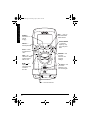
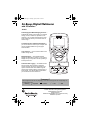
/ mA/A —
measures
current.
/ µA/A —
measures
current.
Guard
WARNING:
THE GUARD
PROTECTS
AGAINST
ELECTRIC
SHOCK. DO
NOT
REMOVE IT.
A Quick Look at Your Meter
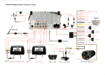
#"37+%-".11-"#6";174"/'6'4
•
—
measures ohms
and capacitance.
–/„ —
checks
continuity
and diodes.
LOGIC/Hz —
measures
frequency and logic.
hFE — lets you
measure the gain
of small-signal,
bipolar transistors.
9
22-812.fm Page 10 Monday, April 8, 2002 1:32 PM
A Quick Look at Your Meter
REL€ — lets you
work with relative
measurements.
RANGE —
selects auto or
manual
ranging.
Hz/DUTY/WIDTH
— measures
frequency, duty
cycle, and pulse
width.
SELECT —
selects options.
HOLD — holds
a measurement
value.
dBm / ~ V —
selects AC voltage
measurement in
dBm or volts.
MAX/MIN — lets
you store
maximum and
minimum
readings.
°C/°F /
V—
displays
temperature and
measures
DC volts.
hFE Socket — lets
you insert a
transistor so you
can check its gain.
OFF — turns the meter off.
10
22-812.fm Page 11 Monday, April 8, 2002 1:32 PM
24'2#4#6+10
Your meter requires one 9-volt battery (not
supplied) for power. For the best performance and
longest life, we recommend a RadioShack alkaline
battery." .
2. If the meter is on, rotate the function selector to
OFF to turn it off. Then disconnect the test
leads if they are connected.
3. Use a Phillips screwdriver to loosen the battery
cover’s screw, then lift off the battery cover.
4. Snap a fresh 9V battery onto the terminals of
the battery clip in the battery compartment.
To avoid electrical
shock, disconnect all of
the meter’s test leads
from any equipment before you install or replace
the meter’s battery.
•
Do not use your meter
until the battery is
properly installed and the
battery cover is in place
and secured.
•
Dispose of an old battery
promptly and properly.
Do not burn or bury it.
Connecting the Test
Leads
•
~
When
appears on the left side of the display or
the meter stops operating properly, replace the
battery.
.
Rý
%100'%6+0)"6*'"6'56".'#&5
Rý
If necessary, slide up the guard on the front of the
meter. Plug the black test lead’s right-angled end
into –COM (common) on the front of the meter, then
plug the red test lead’s right-angled end into +
Ω. If you want to measure current higher than
V.mA.Ω
"
•
5. Replace the battery cover and secure it with
the screw.
The black and red test leads supplied with your
meter are rated for 1000 volts. Use only test leads
of the same rating with the meter. You can order
replacement leads from your local RadioShack
store.
R
"9#40+0)ý
Installing a Battery
Rý
1. If the rubber boot is attached to the meter,
simply pull it off to remove it (see “Using the
Rubber Boot” on Page 12).
R
ALTHOUGH THE TEST
LEADS ARE RATED
FOR 1000 VOLTS, THE
MAXIMUM RATING OF
THIS METER IS 1000
VOLTS DC/750 VOLTS
RMS AC. DO NOT TRY
TO MEASURE
VOLTAGE GREATER
THAN 1000 VOLTS DC/
750 VOLTS RMS AC.
."%#76+10".
•
Use only a fresh battery
of the required size and
recommended type.
•
If you do not plan to use
the meter for a month or
more, remove the
battery. Batteries can
leak chemicals that can
destroy electronic parts.
11
Preparation
+056#..+0)"#"$#66'4;
ý
22-812.fm Page 12 Monday, April 8, 2002 1:32 PM
±"016'"±"
Connecting the Test
Leads
The meter sounds a
warning tone when you set
it to measure anything
except current and you
connect a test lead to +10A
MAX. This reminds you not
to touch the circuit with the
test leads.
Turning the Meter On/
Off/Testing the Display
Using the Meter
If the function selector is not
set to OFF and nothing
appears on the display, the
meter might be in its auto
power shut-off mode. Press
any button to turn on the
meter. If the meter remains
off, rotate the function
selector to OFF, then to any
function except OFF. If the
meter still remains off,
replace the battery (see
“Installing a Battery” on
Page 11).
."%#76+10".
When the meter is not in
use, always leave the
function selector set to
OFF.
12
400mA, plug the red test lead’s right-angled e n d
i n t o +10A MAX i n s t e a d o f + V.mA.Ω
Ω. ±
75+0)"6*'"56#0&
The stand on the back of the meter lets you place it
upright on a flat surface for easier viewing. To use
the stand, simply fold it out.
75+0)"6*'"47$$'4"$116
The rubber boot supplied with the meter helps
protect the meter from damage. The keyhole on the
back of the rubber boot lets you hang the meter on
a wall.
Simply slide the meter onto the boot, or pull down
on the bottom of the boot to remove it from the
meter. Use the clips on the back of the rubber boot
to store the test leads while you are not using them.
75+0)"6*'"/'6'4
For the most accurate reading, the temperature
should be between 65° and 83°F (18° and 28°C),
with a maximum of 75% relative humidity. .
6740+0)"6*'"/'6'4"1011((1
6'56+0)"6*'"&+52.#;
To turn on the meter, rotate the function selector to
any function except OFF. To turn off the meter,
rotate the function selector to OFF. ±
To test the meter’s display, turn off the meter, then
hold down HOLD while turning on the meter. The
meter turns on and all segments on the display
appear. Release HOLD to turn off the test.
22-812.fm Page 13 Monday, April 8, 2002 1:32 PM
Follow these steps to familiarize yourself with the
meter’s operation before you use it for the first time.
Rý.
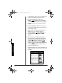
1. Rotate the function selector to select one of the
following functions, then repeatedly press
SELECT to select the function you want.
2QUKVKQP
°C/°F /
V
dBm / ~ V
&GUETKRVKQP
Displays temperature (°C or °F).
Measures DC voltage.
Measures AC voltage in dBm.
Measures AC voltage in volts.
/ µA/A
Measures current, DC 0.4/4 mA and
AC 0.4/4 mA
Measures current, DC 4/10 A and
AC 4/10 A
/ mA/A
Measures current, DC 40/400 mA
and AC 40/400 mA
Measures current, DC 4/10 A
and AC 4/10 A
•
Measures ohms.
Measures capacitance.
–/„
Checks continuity.
Checks diodes.
LOGIC/Hz
Measures logic (HI/LO).
Measures frequency.
hFE
Measures the gain of small-signal
bipolar transistors (using the hFE jack on
the front of the meter).
ý
R
R
"9#40+0)ý
"
Always turn off power to the
circuit you are about to
measure before you probe
the test leads into highvoltage points
."%#76+10".
Be sure to select the correct
function before you touch
the test leads to the circuit
or component to be tested.
Using the Meter
$'(14'";17"56#46
For example, to measure a diode, rotate the
function selector to –/„, then press SELECT.
„ýappears.
2. Your meter automatically enters the auto range
mode when you turn on the meter. In the auto
range mode, AUTO appears and the meter
automatically selects the next higher or lower
range (if available) when the measurement
causes the display to overflow (the meter tries
13
22-812.fm Page 14 Monday, April 8, 2002 1:32 PM
to display 4001 or more units) or underflow (the
meter tries to display 379 or fewer units).
3. To select manual range mode, press
RANGE. AUTO disappears. Then repeatedly
press RANGE until the range you want appears.
The decimal point shifts each time you press
RANGE.
4. Hold down RANGE for about 2 seconds. The
meter exits manual range mode and returns to
its auto range mode.
5. To select the temperature range you want to
display (°C or °F), rotate the function
selector to °C/°F / V, press SELECT once,
then repeatedly press RANGE until 9 or <
appears.
6. Set the meter to the different measurement
ranges. The unit of measure that appears on
the display shows the currently set range. For
example, cL appears in the 400 mV range.
Note the position of the decimal. If &$&&&ýL
appears, the meter is set to measure less than
4 volts. If &&&&L appears, the meter is set to
measure up to 1000 volts.
Using the Meter
Read the range in volts, ohms, capacitance, or
amps as indicated by the position of the decimal point.
4CPIG
400 mV
4V
40 V
400 V
1000 V DC/750 V AC
400 µA
4 mA
40 mA
14
&KURNC[
ZZZ$ZýcL
Z$ZZZýL
ZZ$ZZýL
ZZZ$ZýL
ZZZZýL
ZZZ$Zýµ7
Z$ZZZýc7
ZZ$ZZýc7
22-812.fm Page 15 Monday, April 8, 2002 1:32 PM
400 mA
4A
10 A
400 Ω
4 kΩ
40 kΩ
400 kΩ
4 MΩ
40 MΩ
4 nF
40 nF
400 nF
4 µF
40 µF
&KURNC[
ZZZ$Zýc7
Z$ZZZý7
ZZ$ZZý7
ZZZ$ZýΩ
Z$ZZZýaΩ
ZZ$ZZýaΩ
ZZZ$ZýaΩ
Z$ZZZýCΩ
ZZ$ZZýCΩ
Z$ZZZýd<
ZZ$ZZýd<
ZZZ$Zýd<
Z$ZZZýµ<
ZZ$ZZýµ<
7. Connect the test leads to the circuit you want to
measure. To measure different circuits, see
“Making Measurements” on Page 18. ±ý.
*1.&+0)"#"/'#574'/'06
Press HOLD to hold all indications on the display.
Hold appears and the meter holds the measured
value on the display even if you remove the probes
from the circuit.
To cancel hold, press HOLD again or set the
selector to another setting or press SELECT. Hold
disappears.
±"016'"±"
The display might show a
phantom reading in some
DC and AC voltage ranges
when the test leads are not
connected to a circuit. This
is normal. The high input
sensitivity produces a
“wandering” effect. When
you connect the test leads
to a circuit, the
measurement appears.
."%#76+10".
If Eý< (overflow) appears,
the measured value
exceeds the range for the
selected setting. This is
normal when you measure
resistance or a diode, or do
not have the leads
connected to a component.
If you are measuring
voltage or current when Eý<
appears, immediately
disconnect both probes
from the circuit, then touch
the probes together or
choose another range.
75+0)"4'.#6+8'"/'#574'/'06
You can set the meter so it does not show an
unwanted value that might appear as a result of
internal or other factors. For example, the meter
always shows a small value when you set the
selector to • to measure capacitance, even
when you have not connected the test leads to a
component. (This happens because the meter
15
Using the Meter
4CPIG
22-812.fm Page 16 Monday, April 8, 2002 1:32 PM
±"016'"±"
Using Relative
Measurement
•
If the value you
measured in Step 2 is
greater than the value
you measured in Step 4,
the meter shows a
negative value. This is
not a malfunction.
•
Eý< appears if you
measure values outside
the meter’s currently set
range. If Eý< appears,
immediately disconnect
both probes from the
circuit, then touch the
probes together or
choose another range.
•
Using the Meter
•
16
The meter displays values greater than 4000
counts as long as the
range used is not an
overflow range. (A count
is the smallest unit the
meter can measure). For
ex-ample, if you store
–3.500 volts as a
reference, then measure
+3.500 volts, the meter
displays 7.000 volts.
You cannot set Eý< as a
reference value.
measures its own internal capacitance, which is
normal). If you set the meter in relative mode with
the small value as reference, it does not display this
value when you measure a component.
You can also set the meter to a baseline reference
value. For example, if you are measuring a power
source that is supposed to be exactly 5 volts AC or
DC, you can set the meter to a baseline reference
value of 5 volts. Then, the meter displays the
amount of voltage above or below 5 volts that the
power source actually emits.
1. Set the meter to any funct ion e xcept ° C / ° F,
dBm, –, „, LOGIC, or hFE.
2. Measure the zero offset (disconnect test leads
for capacitance, or touch the test leads together for other functions) if you want to remove the zero offset from a reading, or connect
the test leads to the component whose measurement you want to use as a reference value.
3. While measuring the zero offset or with the test
leads connected to a component, hold down
REL€. Rel € appears. The meter is set to
manual range mode.
4. Use the meter to make a measurement. ±
To reset a relative measurement, press REL€ again
or set the function selector to another setting.
#761/#6+%"219'4"1((
Your meter conserves power by automatically
turning off about 30 minutes after the last time you
changed a setting (even if you are making
measurements), unless RS232 appears on the
display (see “Configuring/Using the Meter and
Software” on Page 29) or you disable the automatic
power off feature (see “Using Power Lock” on
Page 17).
22-812.fm Page 17 Monday, April 8, 2002 1:32 PM
To turn the meter back on after it automatically
turns off, press any button.
75+0)"219'4".1%-
To set the meter so it does not turn off
automatically, set the function selector to OFF to
turn it off. Hold down HOLD and SELECT at the
same time, then turn on the meter. FBeY appears
until you release HOLD and SELECT. The meter sets
itself to its normal test mode and does not
automatically turn itself off. ±
±"016'"±"
The meter automatically
sets itself to its power lock
mode while you use it to
monitor (see “Using
Monitor”).
To reset the meter so it automatically turns itself off,
turn off the meter then turn it back on. The meter
automatically turns itself off after about 30 minutes.
75+0)"/10+614
You can use the meter to monitor maximum and
minimum readings in a circuit, saving both readings
for you to check.
Using the Meter
As the meter monitors, it displays the minimum or
maximum value it measured and stores those
values. If the meter measures a value higher than
the stored maximum value or lower than the stored
minimum value, it updates the value it stored with
the new value. The meter automatically sets itself to
manual mode when you use it to monitor.
1. Set the meter to any functi on e xce pt ° C / ° F,
dBm, –, „, LOGIC, or hFE.
2. Connect the test leads to the circuit you want to
measure. To measure different circuits, see
“Making Measurements” on Page 18.
3. Press RANGE. AUTO disappears. Then
repeatedly press RANGE until the range you
want appears.
4. Press MAX/MIN until CWn appears on the left
side of the display (to set the meter to record
the maximum and minimum values). Then
17
22-812.fm Page 18 Monday, April 8, 2002 1:32 PM
Making Measurements
repeatedly press MAX/MIN to read the currently
selected maximum value (if CWn appears) or
the currently selected minimum value (if C_d
appears).
±"016'"±"
When the meter is set to its
voltage or current function
and the input is out of the
setting’s range, Eý<ýappears
on the display and CWn or
C_d flashes on the left side
of the display.
5. To pause monitoring, press HOLD. Hold
appears. To continue monitoring, press HOLD
again. Hold disappears. ±
To exit the monitor mode, press MAX/MIN for more
than 2 seconds. CWn or C_d disappears.
/#-+0)"/'#574'/'065
ý
•
•
R
"9#40+0)ý
R
"
Never clamp a test lead
to a hot wire (usually red,
black, or blue in AC
wiring circuits). If one
lead is clamped to a hot
wire and you touch the
meter’s other probe. you
could receive an electric
shock.
The maximum input limit
for DC voltage
measurement is 1000 V
DC. To avoid electrical
shock and damage to
the meter, never try to
measure a DC voltage
above 1000 volts.
/'#574+0)"&%"81.6#)'
1. Set the function selector to °C/°F /
V.
Rý
2. If necessary, press SELECT to select DC
voltage measurement.
3. If the meter is set to automatic range control,
the meter automatically moves to the range
that gives the best reading.
4. To set manual range control, press
RANGE. AUTO disappears. Repeatedly press
RANGE to change the range.
5. Touch the probes to the circuit you want to test.
In the 400 V and 400mV ranges, the decimal
point appears in the same position (one place
to the left). To distinguish between the two
ranges, mV appears in the 400mV range and V
appears in the 400 V range.
When the meter is set to the 400mV range, Eý<
continues to appear even if you remove an
over-range input signal. This is not a
malfunction. To clear the display, simply touch
the test leads together or connect them to a
circuit. Eý< disappears.
18
22-812.fm Page 19 Monday, April 8, 2002 1:32 PM
You can use an optional thermocouple module to
measure temperature with your meter. The
thermocouple module you use must output 1mV per
measured °C or °F. The meter can display
temperatures up to 999°C or 999° F.
1. Set the function selector to °C/°F /
V.
2. Unplug both test leads from the meter, plug the
thermocouple’s common plug into –COM
(common) on the front of the meter, then plug
the thermocouple’s +V plug into + V.mA.Ω
Ω.
3. Press SELECT once to select temperature
measurement.
ý
R
/'#574+0)"#%"81.6#)'
1. Set the function selector to dBm / ~ V.
R
2. Repeatedly press SELECT to select the
measurement unit you want to use (dBm or
volts). ±
In dBm mode, relative measurement and monitor modes are disabled.
In the 400 V and 400mV ranges, the decimal
point appears in the same position (one place
to the left). To distinguish between the two
ranges, cL appears in the 400mV range and L
appears in the 400 V range.
R
"9#40+0)ý
Displaying
Temperature
"
The thermocouple module
has not been evaluated by
Underwriters Laboratories.
Do not use the thermocouple to measure objects
when the voltage is above
30 V RMS and 42.4 V peak
or 60V DC.
Measuring AC Voltage
•
Never clamp a test lead
to a hot wire (usually red,
black, or blue in AC
wiring circuits). If one
lead is clamped to a hot
wire and you touch the
meter’s other probe, you
could receive an electric
shock.
•
The maximum input limit
for AC voltage measurement is 750 V AC (RMS).
To avoid electrical shock
and damage to the
meter, never try to
measure an AC voltage
above 750 volts RMS.
4. To select the temperature range you want to
display (°C or °F), repeatedly press RANGE
until 9 or < appears.
5. Touch the thermocouple’s sensor head to the
object you want to test."
R
±"016'"±"
0 dBm is equal to the
consumption power on a
600-ohm resistor with
0.775V voltage drop.
3. If the meter is set to automatic range control,
the meter automatically moves to the range
that gives the best reading.
19
Making Measurements
&+52.#;+0)"6'/2'4#674'
22-812.fm Page 20 Monday, April 8, 2002 1:32 PM
ý
Making Measurements
R
"9#40+0)ý
R
"
Measuring AC Voltage
Riding on a DC Source
Bias
To avoid injury or damage
to your meter, never try to
measure an AC voltage that
is riding on a DC source
bias where the peak AC
voltage exceeds 1000 V
with respect to earth ground.
Measuring ThreePhase AC Voltage
This voltage exceeds the
meter’s rating. Therefore,
you should not connect the
meter to this circuit or to any
equipment connected to the
circuit. Doing so could
present a dangerous shock
hazard to you, and could
also damage the meter.
Measuring DC/AC
Current
Do not apply voltage directly
across terminals. You must
connect the meter in series
with the circuit.
."%#76+10".
Measuring DC/AC
Current
•
Never connect the test
leads across a voltage
source. Doing so can
damage the meter or the
circuit under test. The
maximum input limit for
AC/DC current
measurement is 10A.
(continued)
20
To set manual range control, press RANGE
then change the range (if necessary) by
repeatedly pressing RANGE.
4. Touch the probes to the circuit you want to test.
/'#574+0)"#%"81.6#)'"4+&+0)"10"#"
&%"5174%'"$+#5
To measure AC voltage superimposed on a DC
voltage source bias while ignoring the DC voltage,
follow the steps for measuring AC voltage under
“Measuring AC Voltage” on Page 19.
R
/'#574+0)"6*4''/2*#5'"#%"81.6#)'
Your multimeter is designed primarily to measure
household AC voltages. If you want to measure 3phase, line-to-line voltage, please note the
following:
• Because of the dangers inherent in measuring
three-phase circuit, we strongly recommend
you do not use this meter for such applications.
• The actual voltage can be greater than the
circuit’s rated line-to-ground voltage.
Most 3-phase power circuits are rated by their lineto-line voltage. This voltage is higher than the line
(or phase) to ground voltage. To determine if a lineto-line 3-phase voltage exceeds the rating of this
meter, multiply the rated line-to-ground voltage by
1.732 (the square root of 3). For example, if the
rated line-to-ground voltage is 640 volts, the line-toline voltage is 640 × 1.732 = 1108 V AC.
R
/'#574+0)"&%1#%"%744'06
To measure AC or DC current, you must break the
circuit and connect the test leads to two circuit
connection points. The connection must be in series
.
with the circuit under test.
Rý
1. Rotate the function selector to / µA/Aýfor
0.4/4mA and 4/10A ranges or / mA/A for 40/
400mA and 4/10A ranges.
22-812.fm Page 21 Monday, April 8, 2002 1:32 PM
."%#76+10".
Measuring DC/AC
Current
(continued)
3. Remove the power from the circuit under test
and discharge all capacitors.
4. Plug the black test lead into –COM and the red
test lead into the appropriate jack.
5. Connect the meter’s test leads in series with
the circuit.
6. Apply power and read the current value. If the
measurement is less than 400mA and the red
test lead is connected to +10A MAX, remove
power from the circuit.
If your measurement exceeds the selected
range, Eý< appears until the measured voltage
or current is reduced to a value below the
selected range.
Ω.
7. Move the red test lead to + V.mA.Ω
•
If you do not know the
amount of current in the
circuit you are
measuring, always
connect the red test lead
to +10A MAX.
Measuring Resistance
Your meter has a circuit to
protect the resistance range
from over-voltage.
However, to avoid
accidentally exceeding the
protection circuit’s rating
and to ensure a correct
measurement, never
connect the test leads to a
source of voltage while the
function selector is set to
•.
8. Rotate the function selector to / µA/Aýor /
mA/A depending on the value you measured in
Step 6.
9. Reapply power to the circuit.
If you are measuring DC current and the current’s
polarity is negative, – appears before the value.
/'#574+0)"4'5+56#0%'
The resistance measuring circuit in your meter
compares the voltage gained through a known
resistance (internal) with the voltage developed
.
across an unknown resistance.
Rý
1. Remove all power from the circuit under test
and discharge all capacitors.
ý
R
"9#40+0)ý
R
"
Be sure the circuit under
test has all power removed
and any associated
capacitors are fully
discharged before you
make a resistance
measurement.
21
Making Measurements
2. Press SELECT once to set the meter to
measure AC current (∼
∼ appears). Otherwise,
repeatedly press SELECT to set the meter to
measure DC current (∼
∼ disappears).
22-812.fm Page 22 Monday, April 8, 2002 1:32 PM
Making Measurements
±"016'"±"
Measuring Resistance
•
•
With no resistance
connected across the
test leads (meaning
resistance is infinite),
Eý< appears when you
set the meter to
measure resistance.
This is normal.
If you are measuring
resistance of about 1MΩ
or more, the display
might take a few
seconds to stabilize.
This is normal.
2. Rotate the function selector to •.
Ω
Ω, or MΩ
3. If necessary, press SELECT until Ω, KΩ
appears to set the meter to measure
resistance. ±
4. Touch the test leads across the resistor you
want to measure, or remove one of the leads of
the component you want to measure from its
circuit and touch the test leads across the
resistor. If the meter is set to automatic range
control, it automatically moves to the proper
range.
If you set the meter to use manual range,
repeatedly press RANGE to set manual-range
control and change the range (if necessary). ±
As with the voltage range, use the measuring units
that appear on the display to determine the current
resistance range. If only Ω appears, the values of
the measurements are in ohms. If A and Ω appear,
the meter is measuring kilohms (1 kilohm = 1000Ω).
If C and Ω appear, the meter is measuring
megohms (1 megohm = 1,000,000 Ω).
If you want to accurately measure a very small
resistance, you can view the resistance of the
meter’s test leads, then subtract that resistance
from the measured value. To measure the
resistance of the test leads, simply touch the ends
of the leads together. The meter selects the 400Ω
scale and displays the resistance of the test leads.
You can also use the meter’s relative function to do
this (see “Using Relative Measurement” on
Page 15).
22
22-812.fm Page 23 Monday, April 8, 2002 1:32 PM
/'#574+0)"%#2#%+6#0%'
Capacitance measurement accuracy depends on
the measurement method and differs with different
types of capacitors. The meter’s measurement is for
reference only.
1. Remove all power from the circuit under test
and discharge all capacitors.
2. Rotate the function selector to •.
3. Set the meter to measure capacitance by
pressing SELECT. nF or µF appears. Then
repeatedly press RANGE if necessary to
manually select the range you want.
."%#76+10".
Measuring
Capacitance
Do not connect the test leads
to a source of voltage with
the function selector set to
. This could damage
the meter or the circuit
being tested.
•
Checking Continuity
Do not connect the test leads
to a source of voltage with
the selector set to /
.
This could damage the meter
or circuit being tested.
–„
±"016'"±"
•
The voltage applied
across electrolytic
capacitors affects their
measured values. That
is, a measurement taken
with a low voltage will be
lower than one taken
with a voltage near the
capacitor’s voltage
rating. Since this meter
cannot use high voltage
to set the electrolyte, it
cannot measure the
absolute value of
capacitance.
•
Low-value capacitors
might match or be close
to the meter’s actual
input capacitance. To
measure low capacitance values, use the
meter’s relative feature
to adjust the meter for
(continued)
4. Attach the red test lead to the positive side of
the capacitor and attach the black test lead to
the negative side of the capacitor. Or, remove
one of the leads of the capacitor you want to
measure from its circuit and connect the test
leads to the capacitor’s matching (positive or
negative) terminals. The measured value
appears. ±
%*'%-+0)"%106+07+6;
You can use the meter to check for shorted or open
electrical circuits. .
1. Remove all power from the circuit under test
and discharge all capacitors.
2. Rotate the function selector to –/„.
3. To select the continuity function, press SELECT
until –ýappears at the top of the display.
23
Making Measurements
The capacitance measuring circuit in your meter
charges a connected capacitor to a specific voltage
level, then discharges the capacitor to a lower
voltage. The meter measures the amount of time
takes to discharge the capacitor. .
22-812.fm Page 24 Monday, April 8, 2002 1:32 PM
Making Measurements
4. Touch the test leads across the circuit you want
to measure. Shrt appears and the buzzer
sounds if the circuit resistance is less than
about 50 ohms (meaning the circuit is
continuous or shorted). Open appears and the
meter’s buzzer does not sound if the circuit
resistance is greater than about 50 ohms
(meaning the circuit is not continuous).
±"016'"±"
(continued)
its own capacitance
(see “Using Relative
Measurement” on
Page 15).
Checking Diodes
•
•
When you test a silicontype semiconductor, the
values might vary
depending on the
temperature.
The values that appear
during a diode check
show the actual forward
voltage (2.0V max). If
the voltage exceeds
2.0V, Eý<ýappears. The
meter cannot check this
diode.
."%#76+10".
Do not connect the test
leads to a source of voltage
with the function selector
. This could
set to /
damage the meter or the
circuit being tested.
–„
24
%*'%-+0)"&+1&'5
This procedure lets you check diodes, transistors,
and other semiconductors for opens, shorts, and
normal operation. It also lets you determine the
forward voltage and polarity for diodes. (This is
handy when you need to match a diode.) You can
also check LEDs using this procedure. .#±
You can also use the meter’s hFE feature to quickly
measure the gain of small-signal, bipolar
transistors. See “Measuring hFE” on Page 27 for
more information.
1. Remove all power from the circuit under test
and discharge all capacitors.
2. Rotate the function selector to –/„.
3. To select the diode function, press SELECT
once. „appears on the display.
4. Connect the test leads to the device you want
to check, or remove one of the leads of the
component you want to measure from its circuit
and connect the test leads to the component.
Note the first reading.
5. Reverse the test leads and note the second
reading.
If one reading shows a value and the other is
overrange (Eý< appears) the device is good. If Eý<
appears during both readings, the device is open. If
both values are very small or zero, the device is
shorted.
22-812.fm Page 25 Monday, April 8, 2002 1:32 PM
Many diodes have a stripe or mark on one side. The
marked side of the diode indicates the diode’s
cathode or negative (–) side. The other side is the
anode or positive (+) side.
If a diode is not marked, you can use your meter to
check the diode’s polarity. As you follow the steps
under “Checking Diodes” on Page 24, connect the
red test lead to one side, connect the black test lead
to the other side, then measure and note the
voltage. Then reverse the test leads and measure
and note the second reading. The side of the diode
where the meter shows a higher voltage using the
red test lead is the anode (+) side. The side of the
diode where the meter shows Eý<ýusing the red test
lead is the cathode (–) side.
."%#76+10".
Measuring Logic
Making Measurements
%*'%-+0)"&+1&'"21.#4+6;
Do not apply more than 5
VDC between terminals.
This could damage the
meter or the circuit being
tested.
/'#574+0)".1)+%
1. Rotate the function selector to LOGIC/Hz. .
2. To select the logic function, press SELECT
once. BE appears.
3. Connect the test leads to the device you want
to check. BE appears if the logic is low (the
voltage is lower than 1.0V). >_ appears if the
logic is high (the voltage is higher than 2.0V)
The actual voltage appears if the logic is
between 1 and 2 V.
/'#574+0)"(4'37'0%;1
&76;"%;%.'127.5'"9+&6*
The meter can measure frequency from 10 Hz to 4
MHz and duty cycle and pulse width with a signal
frequency from 10 Hz to 100 kHz. The amplitude of
a signal is not larger than 10V peak.
1. Rotate the function selector to LOGIC/Hz.
2. To select the frequency function, press SELECT
until Hz, KHz, or MHz appears.
25
22-812.fm Page 26 Monday, April 8, 2002 1:32 PM
Making Measurements
Otherwise, to select the duty cycle or pulse
width function, repeatedly press Hz/DUTY/
WIDTH until å appears (to select duty cycle) or
until µI or cI appears (to select pulse width)
3. If you are measuring frequency, press RANGE if
necessary to select manual range then
repeatedly press RANGE until the range you
want appears.
4. Connect the black test probe to a ground
reference for the signal, and connect the red
test probe to the signal source.
ý
R
"9#40+0)ý
R
"
To avoid electrical shock
and damage to the meter,
never try to measure a
frequency of more than 1
kHz between AC 40 volts
RMS and 750 volts RMS.
±"016'"±"
•
•
26
If the function selector is
set to dBm / ~ V and you
want to set the meter for
maximum sensitivity
when measuring a new
signal, press SELECT to
select the ACV function
then press Hz/DUTY/
WIDTH to select the
frequency function.
To change back to ACV
measurement, press
SELECT once then
repeatedly press
SELECT to select the
ACV display mode (dBm
or volts).
/'#574+0)"#%"81.6#)'"(4'37'0%;
The meter can measure the frequency of an AC
±
voltage, with or without a DC source bias.
Rý
1. If you are measuring AC voltage with a DC
source bias, set the function selector to dBm / ~
V. Otherwise, set the function selector to °C/°F /
V.
2. To select the frequency function, repeatedly
press Hz/DUTY/WIDTH until Hz, kHz, or MHz
appears.
3. If necessary, press RANGE to select manual
range, then repeatedly press RANGE until the
desired range appears.
4. To select the duty cycle or pulse width function,
repeatedly press Hz/DUTY/WIDTH until å
appears (to select duty cycle) or until µS or
mS appears (to select pulse width).
5. If å, µS, or mS appears and you want to select
the frequency function again, repeatedly press
Hz/DUTY/WIDTH until Hz, kHz, or MHz appears.
6. Connect the test leads to the device you want
to check.
/'#574+0)"#%"%744'06"(4'37'0%;
1. Rotate the function selector to / µA/Aýfor
0.4/4mA and 4/10A ranges or / mA/A for 40/
400mA and 4/10A ranges. ±
±"016'"±"
•
If the meter is set to
measure current, it
cannot measure the
frequency of a signal
with DC bias.
•
Press SELECT twice to
set the meter back to the
AC A measurement
function.
2. To select the frequency function, press Hz/
DUTY/WIDTH once.
3. If necessary, press RANGE to select the manual
range, then repeatedly press RANGE until the
desired range appears.
4. To select the duty cycle or pulse width function,
repeatedly press Hz/DUTY/WIDTH until å
appears (to select duty cycle) or until µS or mS
appears (to select pulse width).
5. If å, µS, or mS appears and you want to select
the frequency function again, repeatedly press
Hz/DUTY/WIDTH until Hz, kHz, or MHz appears.
6. Connect the test leads to the device you want
to check in series.
/'#574+0)"h('
You can use the meter to measure the DC gain of
small-signal, bipolar transistors in the hFE range of
1000. .
1. Set the function selector to hFE.
."%#76+10".
To avoid damaging the
meter, do not try to check a
transistor if you do not know
its type and pinout.
2. Unplug both test leads from the meter, then
slide down the guard on the front of the meter.
3. Insert the transistor you want to check into the
hFE socket on the front of the meter, matching
the pinout of the transistor with the labels on
the socket. The transistor’s value appears.
27
Making Measurements
22-812.fm Page 27 Monday, April 8, 2002 1:32 PM
22-812.fm Page 28 Monday, April 8, 2002 1:32 PM
75+0)"6*'"/'6'4"9+6*"#"
%1/276'4
You can connect your meter to a computer, letting
you conveniently monitor and record and log data
over a long period of time. You can even use your
meter to display oscilloscope information on your
computer! For example, you can record changes in
temperature in a refrigerator or voltage changes in a
circuit over a long period of time.
Using the Meter With a Computer
Use the supplied RS-232 cable to connect the
meter to your computer and the supplied software
to display information recorded by the meter on
your computer.
+056#..+0)"6*'"/'6'4N5"51(69#4'1
*#4&9#4'
±"016'"±"
•
•
28
If the CD does not start
automatically, make
sure the CD-ROM
drive's door is
completely shut. If the
CD still does not start,
the auto run option on
your computer might be
turned off. If this
happens, click My
Computer. The window
shows the available
drives on your computer.
Then double-click the
icon for your CD-ROM
drive and double-click
setup.exe. The CD
starts.
The supplied cable fits
only one way. Do not
force it.
To use your meter with your computer, you must
install the supplied Meter View software on your
computer, then connect the meter to the computer.
The Meter View software includes installation files
and a Help Guide. This guide provides more
detailed information about the Meter View
software's features. You can read the guide while
Meter View is running, or print a copy directly to
your printer. To read the guide, click Start,
Programs, Meter View, then select Help.
Follow these steps to install the Meter View
software on your computer. ±
1. Turn on your computer and start the installed
Windows operating system (Windows 95,
Windows 98, Windows ME, Windows 2000, or
Windows XP).
2. Insert the software CD into your CD-ROM
drive. The CD starts automatically.
22-812.fm Page 29 Monday, April 8, 2002 1:32 PM
3. After you finish installing the software, restart
your computer.
4. Connect one end of the supplied RS-232 cable
to the jack on top of the meter, then connect
the other end to your computer’s serial port.
You must configure your meter to work with the
Meter View software and the software to work with
your meter.
1. Make sure the meter is connected to your
computer (see “Installing the Meter’s Software/
Hardware” on Page 28).
2. On your computer, click Start, Programs, then
Meter View. The Meter View software starts.
3. On your meter, rotate the function selector to
any function except OFF. Then hold down
SELECT and RANGE together. RS232 appears
on the meter’s display.
±"016'"±"
•
If you select the wrong
COM port, an error
message appears.
Repeat Step 4 to select
the correct COM
port.The supplied cable
fits only one way. Do not
force it.
•
The Meter View software
stops communicating
with the meter if the
connection between the
meter and the computer
fails. If this happens,
check the connection
between the meter and
the computer and make
sure RS232 still
appears on the meter’s
display. Then repeat
Step 5 in this section.
4. On your computer, select the COM port where
you connected the meter by pulling down
Option then COM Port then clicking COM1,
COM2, COM3, or COM4.
5. On your computer, set up the meter to work
with your computer by clicking the
icon or
pulling down Run then clicking Start. Data is
transmitted from your meter to your computer.
The display you see on the meter also appears
on your computer. ±
6. Follow the steps listed in the Meter View
software’s Help Guide to configure and use the
software with the meter.
29
Using the Meter With a Computer
%10(+)74+0)175+0)"6*'"/'6'4"
#0&"51(69#4'
22-812.fm Page 30 Monday, April 8, 2002 1:32 PM
ý
R
"9#40+0)ý
Cleaning
R
"
•
Do not let any water drip
inside the meter while
cleaning it.
•
Make sure that the meter
is completely dry before
using it.
Replacing the Fuses
•
•
To avoid electric shock,
you must disconnect the
test leads before you
remove the battery cover
and back cover.
Do not operate your
meter until the back
cover is in place and
secured.
."%#76+10".
Care and Maintenance
Do not use a fuse brand or
rating other than those
specified here. Doing so
might damage your meter.
You can order the fuses
through your local
RadioShack store.
%#4'"#0&"/#+06'0#0%'
Keep the meter dry; if it gets wet, wipe it dry
immediately. Use and store the meter only in
normal temperature environments. Handle the
meter carefully; do not drop it.
%.'#0+0)
To keep the meter looking new, occasionally wipe it
with a cloth slightly dampened with water. Do not
use harsh chemicals, cleaning solvents, or strong
detergents to clean the meter."
Rý
4'2.#%+0)"6*'"(75'5
If the meter does not work, you might need to
replace one or both of the fuses with the spare
fuses we have included with your meter. The spare
fuses are inserted in a plastic holder inside the
meter’s cabinet near the RS-232 connector on top
of the meter.
The meter contains a 500mA, 250V ceramic fuse
(Littelfuse 314.500) and a 12A, 250V ceramic fuse
(Littelfuse 314012). .
If the meter is on, rotate the function selector to OFF
to turn it off. Then disconnect the test leads if they
are connected.
1. Use a Phillips screwdriver to loosen the battery
cover’s screw, then lift off the battery cover.
2. Remove the battery.
3. Use a Phillips screwdriver to loosen the screws
from the back cover and gently pull apart the
case.
Rý
4. To remove the fuse, gently pull the red ribbon
holding it. The fuse pops out.
5. If the fuse is blown, discard it and save the
ribbon. Then remove the spare fuse from the
30
22-812.fm Page 31 Monday, April 8, 2002 1:32 PM
plastic holder and insert it into the fuse holder
through the loop of the attached ribbon.
6. Replace the back cover and secure it with the
screws.
Care and Maintenance
7. Reinstall the battery (see “Installing a Battery”
on Page 11), then replace the battery cover
and secure it with the screw.
31
22-812.fm Page 32 Monday, April 8, 2002 1:32 PM
Limited Ninety-Day Warranty
This product is warranted by RadioShack against manufacturing defects in material and workmanship under normal use for ninety (90)
days from the date of purchase from RadioShack company-owned
stores and authorized RadioShack franchisees and dealers. EXCEPT
AS PROVIDED HEREIN, RadioShack MAKES NO EXPRESS WARRANTIES AND ANY IMPLIED WARRANTIES, INCLUDING THOSE
OF MERCHANTABILITY AND FITNESS FOR A PARTICULAR PURPOSE, ARE LIMITED IN DURATION TO THE DURATION OF THE
WRITTEN LIMITED WARRANTIES CONTAINED HEREIN. EXCEPT
AS PROVIDED HEREIN, RadioShack SHALL HAVE NO LIABILITY
OR RESPONSIBILITY TO CUSTOMER OR ANY OTHER PERSON
OR ENTITY WITH RESPECT TO ANY LIABILITY, LOSS OR DAMAGE
CAUSED DIRECTLY OR INDIRECTLY BY USE OR PERFORMANCE
OF THE PRODUCT OR ARISING OUT OF ANY BREACH OF THIS
WARRANTY, INCLUDING, BUT NOT LIMITED TO, ANY DAMAGES
RESULTING FROM INCONVENIENCE, LOSS OF TIME, DATA,
PROPERTY, REVENUE, OR PROFIT OR ANY INDIRECT, SPECIAL,
INCIDENTAL, OR CONSEQUENTIAL DAMAGES, EVEN IF RadioShack HAS BEEN ADVISED OF THE POSSIBILITY OF SUCH
DAMAGES.
Some states do not allow limitations on how long an implied warranty
lasts or the exclusion or limitation of incidental or consequential damages, so the above limitations or exclusions may not apply to you.
In the event of a product defect during the warranty period, take the
product and the RadioShack sales receipt as proof of purchase date to
any RadioShack store. RadioShack will, at its option, unless otherwise
provided by law: (a) correct the defect by product repair without charge
for parts and labor; (b) replace the product with one of the same or similar design; or (c) refund the purchase price. All replaced parts and
products, and products on which a refund is made, become the property of RadioShack. New or reconditioned parts and products may be
used in the performance of warranty service. Repaired or replaced
parts and products are warranted for the remainder of the original warranty period. You will be charged for repair or replacement of the product made after the expiration of the warranty period.
This warranty does not cover: (a) damage or failure caused by or attributable to acts of God, abuse, accident, misuse, improper or abnormal
usage, failure to follow instructions, improper installation or maintenance, alteration, lightning or other incidence of excess voltage or current; (b) any repairs other than those provided by a RadioShack
Authorized Service Facility; (c) consumables such as fuses or batteries; (d) cosmetic damage; (e) transportation, shipping or insurance
costs; or (f) costs of product removal, installation, set-up service adjustment or reinstallation.
This warranty gives you specific legal rights, and you may also have
other rights which vary from state to state.
RadioShack Customer Relations, 200 Taylor Street, 6th Floor, Fort
Worth, TX 76102
We Service What We Sell
RadioShack Corporation
Fort Worth, Texas 76102
12/99
22-812
AO0069ACA1
03A02
Printed in China