1
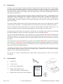
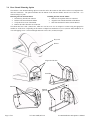
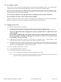
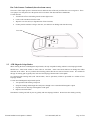
EC3000 Series P/N: 71U-1409-300K © 2008, REV 20 Installation & Operator’s Manual www.unimark.com Unimark Service: USA #: (800) 255-6356 or (740) 201-0080 Table Of Contents 1.0 2.0 3.0 4.0 5.0 6.0 7.0 8.0 9.0 10.0 11.0 12.0 13.0 Introduction ----------------------------------------------------------------------------------------------------Items Included -------------------------------------------------------------------------------------------------Installation -----------------------------------------------------------------------------------------------------3.1 Unpacking 3.2 Counter Top Location 3.3 Rear Shroud Option 3.4 Rear Shroud Mounting Option 3.5 In-Counter Location 3.6 Plugging into the Unit Host RS-232 Serial Interface Specifications -------------------------------------------------------------4.1 Hardware Interface 4.2 Data Structure ASCII Control Character List -----------------------------------------------------------------------------Bar Code Reading Operation ------------------------------------------------------------------------------6.1 Bar Code Coupon Reading Using the Counter Top Version 6.2 Bar Code Coupon Reading Using the In-Counter Version 6.3 Bar Code Data and Configuration ATB MAG Swipe Reading Operation (optional) ------------------------------------------------------7.1 Installing the Magnetic Swipe Reader Option 7.2 Swiping ATB Magnetic Coupons 7.3 Image Mode Operation 7.4 PECTAB Mode Operation Operator Controls / Indicators ----------------------------------------------------------------------------8.1 Eject Button 8.2 Reset Button 8.3 Visible Indicator Intensity Adjustment 8.4 Audible Indicator Intensity Adjustment 8.5 Power ON Indicator 8.6 Boarding Status Indicator 8.7 Optional Passenger (PAX) Display Cleaning -------------------------------------------------------------------------------------------------------9.1 Bar Code Scanner 9.2 ATB MAG Reader Troubleshooting ---------------------------------------------------------------------------------------------Customer/Technical Support -----------------------------------------------------------------------------11.1 Return Authorization/Customer Service 11.2 Technical Support Commands and Responses --------------------------------------------------------------------------------12.1 AEA Commands/Sequences 12.2 AEA Error Messages Unimark Products, LLC. Warranty Statement -------------------------------------------------------- Page 3 Page 3 Page 4 Page 8 Page 8 Page 9 Page 11 Page 15 Page 17 Page 19 Page 20 Page 21 Page 24 FCC Emission Interference This device complies with Part 15 of the FCC Rules. Operation is subject to the following two conditions: (1) This device may not cause harmful interference, and (2) This device must accept any interference received, including interference that may cause undesired operation. Any changes or modifications not expressly approved by Unimark could void the operator’s authority to operate the equipment under these conditions and rules. Note: This equipment has been tested and found to comply with the limits for a Class A digital device, pursuant to part 15 of the FCC Rules. These limits are designed to provide reasonable protection against harmful interference when the equipment is operated in a commercial environment. This equipment generates, uses, and can radiate radio frequency energy and, if not installed and used in accordance with the instruction manual, may cause harmful interference to radio communications. Operation of this equipment in a residential area is likely to cause harmful interference in which case the user will be required to correct the interference at their own cost. EC3000 Installation and Operator’s Manual 71U-1409-300K; REV 20 Page 2 of 24 1.0 Introduction: The Express Check 3000 compact Boarding Gate Reader or BGR (hereafter referred to as the Unit) is a small footprint, fast, and versatile airline document reader, incorporating an internal bar code image scanning device capable of reading all industry standard 1D and 2D symbologies. The Unit also provides for a number of externally connected options for ATB and credit card magnetic stripe reading, coupon and receipt printing, OCR reading, keypad/display interfaces, and other serially connected devices. The Unit incorporates a number of host interface options, which are configurable at the factory. A standard DB-9 RS-232 Asynchronous Serial Communication port is available for interface to the host system. The DB-9 host interface port is configured as a DCE unit allowing for a straight 1:1 connection to a DTE host system (this is identical to the EC2000/2000se). This RS-232 connection is also available using an RJ-45 style connector, which replaces the Ethernet option when installed. The Unit also provides Ethernet (RJ-45 connection) and USB interface options, which are also designated for connection to the host system or network PC. Two additional RS-232 serial connections are provided for external option interface. The Unit is designed to fit into airline podiums or set atop work stations utilizing a minimum of counter space. The Counter Top EC3000 incorporates a lockable mounting platform to secure the Unit to any counter surface. The magnetic stripe reader option will accept full size ATB coupons, the ATB flight coupon section, the ATB boarding pass stub, and Wallet type coupons in any of these configurations as well as standard credit cards. The Unit uses an internal audible alarm. This is primarily used to provide an audible “Do Not Board” indication after reading ATB magnetic or bar code data and the host system has determined that the passenger data does not match the current flight. The Unit is also designed to provide an internal audible indicator when bar code data has been sent to the host system. The Unit incorporates a large visual light source to provide a clear GREEN and RED indicator, which indicates either an “Ok to Board” or “Do Not Board” scenario (controlled by the host) after the appropriate command is received from the host. The Character Display option provides visible feedback of processes being performed and the status of the Unit, using various Auto or Host Controlled messages. A functional reset button has been incorporated to allow the operator to reset the read state of the unit (eject coupons or clear data from the memory) so that it is ready to read another coupon. Additional controls are provided to allow the operator to set the visible and audible indicator levels. The Unit uses an external auto-switching power supply module, allowing operation in both 110 and 220VAC environments. 2.0 Items Included: 2.1 EC3000 Unit 2.2 AC Power Cord 2.3 External Power Supply Module 2.4 Manual or Quick Reference Card Product CD (available on Unimark Website) 2.5 Optional items such as interface cables & adaptors Page 3 of 24 71U-1409-300K; REV 20 EC3000 Installation and Operator’s Manual 3.0 3.1 Installation Unpacking Open the shipping carton. Remove the accessory items and lift the Unit from the carton, ensuring a firm grip on the base of the Unit. Retain original shipping carton and packing material for future shipping or storage purposes. Take caution of the scanner window when lifting, carrying, and installing the Unit. 3.2 Counter Top Location The EC3000 Counter Top version of the Unit is designed to be placed or mounted on a flat stable area and its compact size allows positioning on all common airline podium and counter locations (surfaces and side attachments). The Unit must be installed on a flat and stable surface. Do not install the Unit where it will be exposed to direct sunlight. Sunlight will affect the bar code scanner’s ability to read boarding passes or properly lock onto the scan stand symbol if applicable. Sunlight will also affect the readability of the display and the indicator light source. 3.3 Rear Shroud Option The Unit has a rear shroud option to cover and protect the cables and connectors. The option latches onto the rear of the Unit and is removed using a key lock. Removing the Shroud 1. Insert the key into the lock and turn 2. Pull the Shroud and Unit from each other Installing the Shroud 1. Make sure all required cables are connected 2. Align the Shroud with the rear of the Unit 3. Move the Unit and Shroud together until they latch Key Lock Shroud Align tabs with slots EC3000 Installation and Operator’s Manual 71U-1409-300K; REV 20 Page 4 of 24 3.4 Rear Shroud Mounting Option The Unit has a rear shroud mounting option to secure the unit to the counter or desk surface and to cover and protect the cable and connectors. The option interlinks into the bottom of the Unit and latches onto the rear of the Unit. It is removed using a key lock. Removing the Unit from the Mount 1. Insert the key into the lock and turn 2. Pull the Unit forward from the Mount 3. Verify the Unit is clear of the Mount 4. Remove the cables from the rear of the unit Installing the Unit onto the Mount 1. Make sure all required cables are connected 2. Align the Unit with the Interlinks of the Mount 3. Slide Unit back until it latches into the Shroud The Mount has four 0.200” (5mm) holes, which are used to secure it to an adaptor or counter using the appropriate machine or wood screws. Depending on the counter or adaptor use standard 6-32 or 8-32 (3mm or 4mm) machine or #6 or #8 self-tapping screws. Screw head height must not exceed .180” (4.5mm) in height. Key Lock Shroud Align tabs with slots Interlinks Interlinks Mountin g Screws Page 5 of 24 71U-1409-300K; REV 20 EC3000 Installation and Operator’s Manual 3.5 In-Counter Location The In-Counter version of the Unit is designed with the typical installation methodology to place it in a counter opening so that the top of the unit sits relatively flush with the top surface (like a retail store’s in-counter scanner). However, the In-Counter version is not limited to this type of installation, and it may be placed on a flat stable area just like its counter top version, and like its counterpart, the compact size allows positioning on all common airline podium and counter locations (surfaces and side attachments). The Unit must be installed on a flat and stable surface or mounted securely in various orientations. Do not install the Unit where it will be exposed to direct sunlight. Sunlight will affect the bar code scanner’s ability to read boarding passes or properly lock onto the scan stand symbol if applicable. Sunlight will also affect the readability of the display and the indicator light source. 3.6 Plugging into the Unit The Unit has the following physical connections: 3.6.1 A Locking DC power connection. This matches the plug from the external power supply module. The external power supply module incorporates an IEC 320 power connection accepting 110/220VAC (50/60Hz). The power supply module must be plugged into a properly grounded outlet to comply with electrical safety standards. Do not install or unplug the DC cable until the switch on the power supply module has been placed in the OFF (O) position. Installing or unplugging this cable when the switch is in On (I) position may cause damage to the Unit’s electronics. 3.6.2 A DB-9(F) RS-232 host interface connection. This connection is configured as DCE. A simple straight 1:1 cable quickly interfaces the Unit to a standard connection on a typical PC based host system. 3.6.3 An optional RJ-45 connector may be installed (in place of the Ethernet connector) to provide an alternate RS-232 host interface connection. When the RJ-45 RS-232 connector is installed it is wired in parallel with the DB-9 connector, so the two must never be connected at the same time. 3.6.4 An RJ-45 Ethernet host interface connection. 3.6.5 A Type-B USB host interface connection. 3.6.6 Two auxiliary (AUX) RS-232 interface connections: 3.6.6.1 AUX 1 is primarily for connection to the optional magnetic stripe reader. 3.6.6.2 AUX 2 is targeted for an optional external printing device, but any RS-232 device may be connected so long as the firmware supports the required communications protocol. EC3000 Installation and Operator’s Manual 71U-1409-300K; REV 20 Page 6 of 24 Counter Top Version Connector Access Page 7 of 24 71U-1409-300K; REV 20 EC3000 Installation and Operator’s Manual 4.0 Host RS-232 Serial Interface Specifications 4.1 Hardware Interface The Unit provides an RS-232 Asynchronous Serial Communications port to interface to the Host system. This connection is provided using a single DB-9 female pin connector marked HOST or alternately an RJ-45 connector. The Unit is configured as a DCE unit and connects to an associated DTE host using a straight 1:1 cable to the DB-9 connector (assuming the host system uses a corresponding DTE DB-9 connector). The pin-out below provides the basic cabling requirements to connect the Unit to a PC type host system serial port. Notes: (1) DB-9 pins 1 and 9 are not required connections. (2) RJ-45 serial connection only applicable if it is installed in place of the Ethernet RJ-45 connector. (3) Pin 1 on the RJ-45 serial connector option will either be a no-connect or a ground connection. Host (DTE) PC/AT or equivalent Pin #, DB-9 Signal Name 1 2 3 4 5 6 7 8 9 4.2 CD RxD TxD DTR Signal GND DSR RTS CTS RING EC3000 (DCE) Signal Flow Pin #, DB-9F N/A N/A Pin #, RJ-45(2)(3) Signal Name 8 3 2 7 8 6 4 5 – Signal GND TxD RxD DSR Signal GND DTR CTS RTS Not Connected (1) 1 2 3 4 5 6 7 8 9(1) Data Structure The Unit uses an asynchronous serial data transmission method. Data is sent based on any combination of the following: 5.0 Baud Rate Data Length Parity Stop Bit 115200, 57600, 38400, 19200, 9600, 4800, 2400, 1200 8, 7 None, Even, Odd 2, 1 ASCII Control Character List ACK - Acknowledge character (06HEX). Notifies host or Unit that the previous message was received correctly. BEL - BEL character (07HEX). May be used to initiate a beep from the Unit (depends on FW option). CR - Carriage Return character (0DHEX). Used in conjunction with LF to separate magnetic TRACK and BLOCK fields. DC1 - XON character (11HEX). Used to indicate that the host serial port is ready. Also used to identify Track 1/Block 1 magnetic data in IMAGE mode. DC2 - (12HEX). May be used to initiate a dual tone beep from the (depends on FW option). Also used to identify Track 1/Block 2 magnetic data in IMAGE mode. DC3 - XOFF character (13HEX). Used to indicate that the host serial port is NOT ready. Also used to identify Track 1/Block 3 magnetic data in IMAGE mode. ! “ # - ID characters (21 – 22 – 23HEX). Used to identify Track 2/Blocks 1, 2 & 3 magnetic data in IMAGE mode. 1 2 3 - ID characters (31 – 32 – 33HEX). Used to identify Track 3/Blocks 1, 2 & 3 magnetic data in IMAGE mode. ABC - ID characters (41 – 42 – 43HEX). Used to identify Track 4/Blocks 1, 2 & 3 magnetic data in IMAGE mode. ETX - End Of Text character (03HEX). Used to suffix the PECTAB format table and commands being sent to the Unit. Used by the Unit to suffix magnetic data in image mode and command responses. [ETX] may be a series of characters. LF - Line Feed character (0AHEX). Used in conjunction with CR to separate magnetic TRACK and BLOCK fields. NAK - Negative Acknowledge character (15HEX). correctly. NUL - NULL pad character (00HEX). Character is typically ignored by the Unit unless it is being passed through to one of the device ports, part of an [STX] or [ETX] sequence or used in a communications protocol such as an LRC or DRC. SOH - Start Of Header character (01HEX). Sometimes used to prefix special commands or messages. STX - Start Of Text character (02HEX). Used to prefix the PECTAB format table and commands being sent to the Unit. Used by the Unit to prefix magnetic data in image mode and command responses. [STX] may be a series of characters. EC3000 Installation and Operator’s Manual Notifies host or Unit that the previous message was NOT received 71U-1409-300K; REV 20 Page 8 of 24 6.0 6.1 Bar Code Reading Operation Bar Code Coupon Reading Using the Counter Top Version The integrated bar code scan engine target area is located near the center of the main case top surface. A coupon present (or detection) beam is located just in front of this target area. When a coupon cuts this beam, the scan engine is automatically triggered to look for (or scan for) any bar codes that come into the target area. The Unit provides an audible indication when bar code data is “transmitted” to the host system. The audible indication does not indicate that the passenger data is valid for the specific flight, but only that the bar code presented was accurately “scanned and transmitted”. The AEA CB, CC, and CE (or equivalent non-AEA protocol) commands are used to generate audible and visible indications of “Ok to Board” or “Do Not Board” conditions (same as regular magnetic data reading). Indicator showing RED for “Do Not Board” condition Lines show approximate projected scan location for bar code placement Indicator showing GREEN for “OK to Board” condition Coupon present/detection beam Passenger (PAX) Display The 2D bar code scanner (or scan engine) does not have any laser components. The scan engine uses light emitting diodes (LEDs) that create aimer lines, illumination sources, or target patterns if applicable. Although the operator is exposed to these light sources, testing has been done to demonstrate that the scan engine is safe for this type of application (under normal usage conditions). Just as any light source, the operator should never stare directly into the beam or lens. Page 9 of 24 71U-1409-300K; REV 20 EC3000 Installation and Operator’s Manual 6.2 Bar Code Coupon Reading Using the In-Counter Version The In-Counter version’s integrated bar code image scanner target area is actually a cone area projected up from within the Unit. This allows scanning of coupons as they are brought in towards the scan window. The Unit provides an audible indication when bar code data is “transmitted” to the host system. The audible indication does not indicate that the passenger data is valid for the specific flight, but only that the bar code presented was accurately “scanned and transmitted”. 6.3 Bar Code Data and Configuration The Unit utilizes industry standard bar code image scanners. Scanned bar code data is transmitted to the host system as straight data or with various identifiers (like the AIM ID code) or format characters like the hard coded transaction code “HCTC”. See the typical format examples below: [STX]“Bar Code Data”[ETX] - Standard BC data only format [STX]“Bar Code Data”[CR][ETX] - Standard BC data only with carriage return after the data [STX]‘AIM ID’“Bar Code Data”[ETX] - Standard BC data with AIM ID [STX]‘SITA ID’“Bar Code Data”[ETX] - Standard BC data with SITA “C” Mode ID [STX]‘AEA ID’“Bar Code Data”[ETX] - Standard BC data with AEA 2006 ID [STX]‘HCTC’“Bar Code Data”[ETX] - Standard BC data with HCTC [STX]BCRI#“Bar Code Data”[ETX] - Standard BC data with the AEA BCRI# string (BC inserted) [STX]‘HCTC’BCRI#‘AEA ID’“Bar Code Data”[ETX] - Standard BC format specified in AEA 2006 specification Code versions with specific communication protocols like SITA CUTE specifically define the bar code data format. Generic AEA code versions allow the barcode data format to be customized using any of the available options detailed above or any combination (see example below). [STX]‘HCTC’BCRI#‘AIM ID’“Bar Code Data”[CR][ETX] This example shows the addition of the hard coded transaction code, the BCRI# AEA string, the AIM ID code, and a carriage return added to the end of the BC data. This example shows the order in which these configurable options will be added if enabled; so for example “HCTC” will always be directly after the [STX] and before any other configurable options and the BC data if enabled. The [STX] and [ETX] are typically 02HEX and 03HEX respectively. EC3000 Installation and Operator’s Manual 71U-1409-300K; REV 20 Page 10 of 24 7.0 ATB MAG Swipe Reading Operation (optional) 7.1 Installing the Magnetic Swipe Reader Option 7.1.1 7.1.2 7.1.3 7.1.4 7.1.5 7.1.6 Page 11 of 24 Locate the t-bracket. Orient the reader to the t-bracket so that the interface cable connection located at the rear of the unit. Remove the screws from the bottom of the swipe reader and secure the t-bracket to the reader. Remove the two bottom screws located towards the rear of the Unit. Maintaining the orientation stated above, secure the t-bracket to the Unit. Install the swipe reader interface cable to the AUX1 connector on the rear of the Unit. 71U-1409-300K; REV 20 EC3000 Installation and Operator’s Manual 7.2 Swiping ATB Magnetic Coupons The Unit’s swipe reader option accepts full size ATB coupons, the ATB flight coupon section, the ATB boarding pass stub, and Wallet type coupons. The coupon is swiped through the reader as shown below. Coupons may be swiped forward or backwards through the reader as long as the magnetic strip always faces directly towards the face of the magnetic head. The coupon symbol on top of the reader indicates proper coupon orientation. The Unit reads and transmits the magnetic data from ATB or Boarding Pass coupons and then waits for the host to respond, just as a mechanized magnetic BGR reader processes ATB coupons and boarding passes. If magnetic data is detected by the reader but cannot be processed properly, the Unit will provide an audible and visible indication of the appropriate error condition such as missing PECTAB. EC3000 Installation and Operator’s Manual 71U-1409-300K; REV 20 Page 12 of 24 To avoid damage to the swipe reader, follow these basic precautions: 1. Do not insert multiple coupons. 2. Do not insert torn or mangled coupons. 3. Do not insert any other kind of printout except ATB coupons. 4. Avoid inserting coupons which have staples in them. If this is unavoidable, make sure staples are placed in the center of the coupon. Staples placed at the top or the bottom of the coupon will cause damage to the MAG read heads. Staple Stub Place Staple Here CAUTION: DO NOT PLACE STAPLES IN THESE AREAS SINCE THEY WILL BE DIRECTLY IN LINE WITH THE MAG READ HEADS. Page 13 of 24 71U-1409-300K; REV 20 Staple Safe Zone EC3000 Installation and Operator’s Manual 7.3 Image Mode Operation In this mode, the Unit transmits all data read from the ATB magnetic stripe. Exact format will vary depending on the firmware version (see basic example below): [STX] 11HEX“Track 1/Block 1”[CR][LF] 21HEX“Track 2/Block 1”[CR][LF] 31HEX“Track 3/Block 1”[CR][LF] 41HEX“Track 4/Block 1”[CR][LF] [ETX] 12HEX“Track 1/Block 2”[CR][LF] 22HEX“Track 2/Block 2”[CR][LF] 32HEX“Track 3/Block 2”[CR][LF] 42HEX“Track 4/Block 2”[CR][LF] 13HEX“Track 1/Block 3”[CR][LF] 23HEX“Track 2/Block 3”[CR][LF] 33HEX“Track 3/Block 3”[CR][LF] 43HEX“Track 4/Block 3”[CR][LF] If the Unit cannot read any portion of the ATB magnetic stripe, it will still transmit the coupon data, but use a replacement character such as % to substituted for areas of the magnetic stripe that were unreadable. Once the Unit transmits the data to the host it waits for the appropriate AEA command to know if it should indicate an “Ok to Board” or “Do NOT Board” condition (see PECTAB Mode operation). The Reset button may be used to clear the read state, and another coupon may be processed. 7.4 PECTAB Mode Operation In this mode, the Unit uses one of the downloaded PECTABs to retrieve all specified decoded magnetic data and transmits the data as PECTAB elements per the AEA standard. This mode can drastically reduce the amount of data sent to the host system, and uses the processing power of the Unit to sort through the magnetic data instead of the host system performing this task. If the Unit cannot read a specified portion of the ATB magnetic stripe, a substitution character will be returned. The substitution character is defined by the PECTAB (see command set section). Once the Unit transmits the data to the host it waits for the appropriate AEA command to know if it should indicate an “Ok to Board” or “Do NOT Board” condition (see table below). The host system must respond with one of the AEA commands listed in the table below: AEA Command1 Host Data Status “Ok to Board” – Data sent to host system was valid “Do NOT Board” – Data sent to host system was NOT valid “Do NOT Board” – Data sent to host system was NOT valid Notes: 1. 2. 3. 3 CC CE CB LED2 Audible2 GREEN RED RED NO NO YES Each AEA command sets up the Unit to read the next coupon. Exact response for each command may vary depending on the firmware version, and can vary depending on the usage of the AEA command. Length of response can be set by sending the required time period with the command, as in CC#03, CB#03, and CE#03; where the time period used for each is three seconds. CC command can have several variations for controlling the cut and sort operations. The Reset button may be used to clear the read state, and another coupon may be processed. EC3000 Installation and Operator’s Manual 71U-1409-300K; REV 20 Page 14 of 24 8.0 Operator Controls / Indicators Several operator controls are provided for use during normal operation and to allow the operator to set indicator intensity levels. Refer to “Function Diagram” section for location of controls. 8.1 Eject Button An Eject button is provided to allow the operator to clear the read state of the Unit (eject coupons or clear data from the memory) so that it is ready to process another coupon. This is typically used when the host fails to respond back to the Unit after it sends passenger data to the system. The button’s function is indicated by the label. After reading a magnetic or bar code coupon the Unit waits for a response from the host. Pressing the button at this time will clear the read state of the Unit and allow another coupon to be processed. 8.2 Reset Button A Reset button is provided to allow the operator to perform a hard reset or restart of the Unit (same as a full power cycle). The button’s function is indicated by the symbol. During any point of normal Unit operation, the operator can press the button and hold it for 2 seconds. Release the button when you hear an audible beep and see the Character Display clear. The Unit will complete the boot sequence and attempt to link to the host application (same as powering the Unit on, or off/on). 8.3 Visible Indicator Intensity Adjustment A button is provided to allow the operator to set the intensity level of the Unit’s visible indicator. The button’s function is indicated by the symbol. Power the Unit off. Press and hold the button and power the Unit on. Wait a few seconds after the startup audible beep finishes and then release the button. Now press and release the button to cycle through the available intensity levels of the visible indicator. Stop at the desired level and then power cycle the Unit. This will save the setting and re-initialize the unit. Page 15 of 24 71U-1409-300K; REV 20 EC3000 Installation and Operator’s Manual 8.4 Audible Indicator Intensity Adjustment The Reset button has a secondary function to allow the operator to set the intensity level of the Unit’s audible indicator. The button’s function is indicated by the symbol. Power the Unit off. Press and hold the button and power the Unit on. Wait a few seconds after the startup audible beep finishes and then release the button. Now press and button to cycle through the release the available intensity levels of the audible indicator. Stop at the desired level and then power cycle the Unit. This will save the setting and re-initialize the unit. 8.5 Power ON Indicator A single light source is provided on the base to indicate power on status of the Unit. 8.6 Boarding Status Indicator A large visual indicator provides a clear GREEN and RED visible light source to indicate either an “Ok to Board” or “Do Not Board” status. 8.7 RED/GREEN Boarding Status Indicator PAX Display Optional Passenger (PAX) Display An optional passenger (PAX) display module is available. This option is a standard 2x20 (row x column) Character Display (English character set). Liquid Crystal (LCD) and Vacuum Florescent Display (VFD) modules are available. EC3000 Installation and Operator’s Manual 71U-1409-300K; REV 20 Page 16 of 24 9.0 Cleaning The following section is provided to assist in basic cleaning procedures for the Unit. This section is not intended for regular maintenance or repair of the Unit. 9.1 Bar Code Scanner As a general rule, the bar code scanner elements should require very little cleaning. The scanner components are enclosed to minimize effects from the environment. The primary item requiring cleaning is the scanner lens, which prevents direct access to the scan engine. Over time the lens will become dirty from environmental dust and smudged by operators touching the lens. To clean the lens: 1. Turn the unit off to avoid looking into the scanner light source. 2. Locate a soft non-abrasive/lint free cloth. 3. Wipe the lens area (see diagram below for lens location). 4. If some particles continue to cling to lens area, use canned air to dislodge and clear them away. NOTE: DO NOT use a cloth soaked in any cleaning agent. Some cleaning agents can attack the plastic lens material and cause it to become cloudy instead of transparent. Using an abrasive cloth can scratch the lens, and a cloth that is not lint free may cause more material to be collected on the lens than what was originally present. Lens positioned under the indicator light source NOTE: Be sure and clean the entire lens. Not only does the scan engine capture the bar code image through this component (approximately through the center), but the coupon present/detection beam passes through it to the sensor mounted as shown below. Coupon present sensor Page 17 of 24 71U-1409-300K; REV 20 EC3000 Installation and Operator’s Manual Bar Code Scanner Continued (detection beam source) The source of the coupon present / detection beam is within the base of the unit just before the scan or target area. There is an opaque cover lens placed over the optical device to isolate it from dust and other contaminants. To clean the lens: 1. Turn the unit off to avoid looking into the scanner light source. 2. Locate a soft non-abrasive/lint free cloth. 3. Wipe the cover lens area (see diagram below for lens location). 4. If some particles continue to cling to lens area, use canned air to dislodge and clear them away. Cover lens 9.2 ATB Magnetic Swipe Reader When cleaning the Unit’s ATB Magnetic Swipe Reader, the only acceptable cleaning solution is 99% Isopropyl Alcohol. NEVER use a water based solution to clean rollers or read head. Some water based solutions can damage the rubber elastomer on the rollers. Be very cautious about cleaning pouches like the ones used to clean PC screens. The solution for this type of cleaning pad is typically 50% water and 50% Isopropyl Alcohol and is unacceptable. Use Unimark ATB cleaning cards (P/N 700-5014-000, –200 or equivalent), which are presoaked in a solution of 99% Isopropyl Alcohol. To clean the ATB Magnetic Swipe Reader option: 1. Tear open the ATB cleaning card pouch 2 Swipe the cleaning card through the reader just as though it were a standard ATB magnetic coupon 3. Flip the card over and swipe it through the reader again 4. Repeat several more times Note that the cleaning card will dry out very quickly with 99% Isopropyl Alcohol. Do not insert the cleaning card dry. EC3000 Installation and Operator’s Manual 71U-1409-300K; REV 20 Page 18 of 24 10.0 Troubleshooting The following section is provided to assist in the installation of the Unit, and covers issues that may occur when installing new equipment. This section is not intended for regular maintenance or repair of the Unit. 10.1 Unit will not power up 10.1.1 10.1.2 10.1.3 10.1.4 Verify AC plug is installed into the power supply module. Verify that the power switch on the power supply module is in the ON position (I). Verify that the power supply module is connected/installed into the Unit’s back panel. Check the AC line level. 10.2 Unit will not communicate with the host system 10.2.1 10.2.2 Verify communication cable is plugged into the connector marked HOST on the rear of the Unit, or one of the alternate host interfaces. Verify that the communication parameters of the host system match the Unit’s host port parameters. Unit’s communication parameters and host port selection are done at the factory per customer requirements. 10.3 Unit will not recognize a coupon when swiped through the optional swipe reader slot 10.3.1 10.3.2 Check coupon or label fragments in the swipe path and clear as required. Check that the coupon swipes through the slot and past the magnetic head smoothly. 10.4 Cannot read the display 10.4.1 10.4.2 Verify that the display is not exposed directly to sunlight. Character displays can be difficult to see in sunlight. Relocate the Unit if necessary. Shade the display with your hand. If the display still cannot be seen, return the Unit to Unimark or a certified service center. 10.5 Bar code scanner will not transmit data, appears to be off, or flashes continuously 10.5.1 Verify that the Unit is actually connected to the host system. The Unit will only generate a scan beep if bar code data is “transmitted” to a host that is running an active application. 10.5.2 It is possible that the communication parameters of the scan engine are not set or have been changed. Contact Unimark Service for instructions on how to configure the scan engine or return the Unit for service. 10.5.3 If the bar code scanner illumination LEDs flash continuously or erratically, the scanner may not be detecting movement within the scan window properly: 10.5.4 10.5.5 10.5.3.1 Clean the scanner lens. 10.5.3.2 Verify that the scan area is clean and has not been marked up. 10.5.3.3 Clean the coupon present / detection beam cover lense. If the bar code scanner appears to be powered off: 10.5.4.1 Move a coupon or paper with black print through the scan area. This should cause the scanner to turn on (flash) its illumination LEDs so the scanner can read a bar code. 10.5.4.2 If the LEDs do not turn on, contact Unimark Service for instructions on how to configure the scan engine or return the Unit for service. If the scanner reads bar codes randomly, the scanner lens may be dirty or smudged. Locate the scanner lens area and clean with a soft non-abrasive/lint free cloth. If the Unit still does not function properly, contact Unimark Service at (800) 255-6356 or (740) 201-0080. Page 19 of 24 71U-1409-300K; REV 20 EC3000 Installation and Operator’s Manual 11.0 Customer/Technical Support 11.1 Return Authorization/Customer Service To return a product to Unimark for repair or other assistance, please be prepared with the following information before calling our Customer Service department at (800) 255-6356 or (740) 201-0080 (U.S. office). Customer name and telephone number Product model number or description Product serial number Description of failure Billing address Customer ship to address and method of shipping Repair option selection (Warranty, Flat Rate, Time and Materials or Refurbishment) Our Customer Service Specialist will be entering the information into our system during your call to ensure quick and accurate handling of your return. You will then be given a return authorization number. Perform the following steps to complete the return process: 11.1.1 Prepare item for return to Unimark - Do NOT include accessories, power cable or ancillary items unless directed otherwise by Customer Service. DO NOT SHIP WITH RECEIPT PAPER ROLL INSTALLED! 11.1.2 Packaging – Use original packaging materials or equivalent. If not available, Unimark can provide at a small cost. 11.1.3 Enter the RA # on the packing list and on the outside of the container in at least two locations for easy identification at Unimark. 11.1.4 Shipping label to include return address as well as “ship to”. 11.1.5 Notify your “carrier of choice” for pick-up and delivery to Unimark. 11.2 Technical Support As a purchaser or Unimark authorized third party maintainer of Unimark products, you have the added benefit of technical assistance in the installation, diagnosis and use of Unimark products. Just call our toll free number (800) 255-6356 or (740) 201-0080 and allow the auto-attendant to guide you to our technical support line. A technical support analyst will assist you. To better serve you, please have the product in question on-line and ready to test prior to calling technical support. In addition, have the following information available: Model Number/description Serial Number Failure message/code/description Unimark Products operates a service support center and has access to Certified Service Partners around the world. Contact Unimark for the closest facility to your location. EC3000 Installation and Operator’s Manual 71U-1409-300K; REV 20 Page 20 of 24 12.0 Commands and Responses Commands sent to the Unit are executed as soon as they are received. While executing some processes, the Unit will not be able to receive data from the host system. After reading a coupon, most commands will not be acted on until coupon processing is complete. 12.1 AEA Commands/Sequences AV - CB - AEA Version command generates a status response identifying the AEA Version the firmware supports. HOST command sequence: [STX]AV[ETX] Unit response: [STX]“HCTC”AVOKnn#BGR[ETX] ; where nn = the year of the AEA release This command initiates an audible and red ● visual indicators to alert the operator that the data was not valid. HOST command sequence: HOST command sequence: Unit response: CC - [STX]CB[ETX] [STX]CB#nn[ETX] ; where nn = 00 – 99 for the indicator time period [STX]“HCTC”CBOK[ETX] This command initiates a green ● visual indicator to alert the operator that the data read was valid. HOST command sequence: HOST command sequence: Unit response: [STX]CC[ETX] [STX]CC#nn[ETX] ; where nn = 00 – 99 for the indicator time period [STX]“PTTC”PROK[ETX] ; after magnetic coupon has been read [STX]“HCTC”PROK[ETX] ; after bar code coupon has been read There are variations of this command intended to control cutting and stacking of coupons (such as CC#L1). These are processed in the same manner as the standard CC command. CE - This command initiates a red ● visual indicator to alert the operator that the data read was not valid. HOST command sequence: HOST command sequence: Unit response: CT - KP - Page 21 of 24 [STX]CE[ETX] [STX]CE#nn[ETX] ; where nn = 00 – 99 for the indicator time period [STX]“HCTC”CEOK[ETX] Hard coded Transaction code change or status. As defined by AEA, the transaction code can be any printable ASCII character, from 1 to 5 characters maximum length. Issuing the CT command alone will cause the first response specified below. The second example demonstrates how to change the hard coded transaction code to “UNMK”. HOST command sequence: Unit response: [STX]CT[ETX] [STX]EC3:CTOKEC3:[ETX] HOST command sequence: Unit response: [STX]CTUNMK[ETX] [STX]UNMKCTOKUNMK[ETX] Program Delete or Terminate process is used to stop all internal processing and set up the Unit so that a new version of firmware can be downloaded using the PD command. HOST command sequence: [STX]KP[ETX] Unit response: [STX]“HCTC”KPOK[ETX] 71U-1409-300K; REV 20 EC3000 Installation and Operator’s Manual MG - This is the message command and is used if the operator wants to directly control the optional passenger display. HOST command sequence: [STX]MG#P# A“data for line 1 up to 20 characters”[CR] B“data for line 2 up to 20 characters”[CR][ETX] Unit response: [STX]“HCTC”MGOK#P[ETX] MG command rules: 1. A and B in the example above define line 1 and 2 respectively. 2. Each line may be changed independently, and may be sent in any order. 3. Line data shorter than 20 characters will cause the Unit to blank out the remaining characters. 4. Terminate each line with a [CR] character. 5. Use no more than 20 characters per line and only use printable characters (a-z; A-B; 0-9; exclamation marks). 6. Once the host sends a valid MG command to the unit, all auto display messaging is turned off. 7. Units without the display option will still process valid MG commands and respond to the host. 8. Auto messaging may be turned back on if connection to the host system is lost and then re-established. PC - PECTAB Clear command is used to clear the Flash memory of all PECTAB tables which may be loaded. HOST command sequence: [STX]PC[ETX] Unit response: [STX]“HCTC”PCOK[ETX] PD - Program Download command is used to update the firmware within the Unit. This is performed automatically from the host system without the need of user intervention assuming the host system supports the download function. HOST command sequence: Unit response: [STX]PDvvvvvvvvvvbbbbbbb[ETX] [STX]“HCTC”PDOKvvvvvvvvvv[ETX] Where: vvvvvvvvvv is the 10 digit version number being loaded bbbbbbb is the program data length in bytes (decimal) PS - PECTAB Status command is used to identify all PECTABs currently loaded in the Unit’s Flash memory. HOST command sequence: [STX]PS[ETX] Unit response: [STX]“HCTC”PSOKVxVxVxyzVxyz[ETX] Where: VxVxVxyzVxyz are the loaded PECTABs PT - PECTAB Table load command is used to download a PECTAB table into the Unit’s Flash memory. HOST command sequence: Unit response: [STX]PTs............[ETX] [STX]“HCTC”PTOKVxVxVxyzVxyz[ETX] Where: s is the single digit separator character used in the PECTAB VxVxVxyzVxyz are the loaded PECTABs See AEA specification for complete details. PV - Program Version command is used to identify the firmware version currently installed in the Unit. HOST command sequence: [STX]PV[ETX] Unit response: [STX]“HCTC”PVOKvvvvvvvvvv[ETX] Where: vvvvvvvvvv is the 10 digit version number being reported RC - Read Configuration command is used to identify hardware options installed in the Unit. HOST command sequence: [STX]RC[ETX] Unit response: [STX]“HCTC”RCOK#Annnn#Pnnnn#KP#Bn#Ln#Rnnnn#Sn [ETX] EC3000 Installation and Operator’s Manual Where: Annnn is the agent display size in nn row/nn columns Pnnnn is the passenger display size in nn row/nn column KP is keyboard (KB = full ASCII; KP = keypad; 2 spaces for none) Bn is the number of coupon bins Ln is the number of lockable coupon bins Rnnnn is the External display size in nn row/nn column Sn is the reading option ID value (1 = ATB & BC, 2 = BC only) 71U-1409-300K; REV 20 Page 22 of 24 TO - Time Out setting command is used to set the period of time the Unit will wait for the host to respond to a coupon process (coupon read and data sent to host system) before the process is terminated and the Unit is released to process another coupon. Unit will send an ERR1 response to the host when the timeout occurs. HOST command sequence: [STX]TO[ETX] Unit response: [STX]“HCTC”TOOKnn[ETX] ; Report the current timeout setting HOST command sequence: [STX]TOnn[ETX] Unit response: [STX]“HCTC”TOOKnn[ETX] HOST command sequence: [STX]TO#nn[ETX] Unit response: [STX]“HCTC”TOOK#nn[ETX] Where: nn is the time out period in seconds (01 – 99; 00 = infinite or no timeout) US - Universal Status command generates a status response with PECTAB, Program Version, and Hard Coded Transaction Code status information. HOST command sequence: [STX]US[ETX] Unit response: Notes: 1. 2. 3. 4. [STX]“HCTC”USOKPSOKVxVxVxyzVxyzPVOKvvvvvvvvvvCTOK“HCTC”[ETX] Where: VxVxVxyzVxyz are the loaded PECTABs vvvvvvvvvv is the 10 digit version number being reported “HCTC” is the 1 – 5 character Hard Coded Transaction Code [STX] represents the Start of Text character (02 HEX). Do not send the actual [STX] string. [ETX] represents the End of Text character (03 HEX). Do not send the actual [ETX] string. Refer to the AEA standard for further details on these commands. EC3: is the default Hard Coded Transaction Code “HCTC” for the Unit in Generic AEA mode. This may vary for other operating modes such as CUTE which is 5 spaces by default. 12.2 AEA Error Messages ERR1 - Indicates that the operator has manually reset the coupon processing sequence by pressing the RESET button, or an internal timeout has been reached and the Unit resets the processing sequence. ERR2 - Illogical Command Received. Sent to the host system if any command outside the AEA or Non-AEA commands listed here is used. ERR5 - Unsuccessful Magnetic Processing Operation. Used specifically to notify the host when the Unit detects an ATB Magnetic coupon processing attempt but no magnetic data is read. Possible circumstances for this error would include swiping a coupon upside down, coupon is not encoded, or a non-magnetic coupon/Eticket is used. ERR6 - No parametric table (PECTAB) available for the magnetic coupon swiped. ERR7 - The Unit responds with this error when receiving a non-CB/CC/CE AEA command after starting the processing of an ATB magnetic or Bar Code coupon. ERR8xx - Erroneous element detected in PECTAB download. xx defines the first detected erroneous element. ERR9 - PECTAB exceeds memory capacity of Unit. ERRP - When the Unit receives the KP command, it switches to a special firmware download mode. This error message is sent to the host as a response to any AEA command received except the PD (program download) command and certain others sometimes allowed in this state such as program version (PV). Page 23 of 24 71U-1409-300K; REV 20 EC3000 Installation and Operator’s Manual 13.0 Unimark Products, LLC. Warranty Statement Reader Unimark Products, LLC. warrants to Purchaser that under normal use and service, the products (with the exception of the magnetic read heads, rollers, and belts) purchased hereunder shall be free from defects in material and workmanship for a period of one year (365 days) from the date of shipment by Unimark. Expendable and/or consumable items or parts such as lamps, fuses, and labels are not covered under this warranty. This warranty does not cover equipment or parts, which have been misused, altered, neglected, handled carelessly, or used for purposes other than those for which they were manufactured. This warranty also does not cover loss, damages resulting from accidents, or damages resulting from unauthorized service. Magnetic Read Heads, Rollers and Belts This warranty is limited to a period of one year, (365 days) or 1,000,000 linear inches of use, whichever comes first, for the magnetic read heads, rollers, and belts. This warranty does not cover magnetic read heads, rollers, and belts which have been misused, altered, neglected, handled carelessly, or damaged due to improper cleaning or unauthorized repairs. Warranty Service Procedures If a defect should occur during the warranty period, the defective Unit shall be returned, freight and insurance prepaid, in the original shipping containers, to Unimark Products, LLC. A Return Authorization (RA) number must be issued before the product can be returned. To open an RA, please call the Customer Service Department at (800) 255-6356 or (740) 201-0080. Please print your RA number on the outside of the box and on the shipping document. Include a contact name, action desired, a detailed description of the problem(s), and examples when possible with the defective Unit. Unimark shall not be responsible for any loss or damages incurred in shipping. Any warranty work to be performed by Unimark shall be subject to Unimark’s confirmation that such product meets Unimark warranty. In the event of a defect covered by its warranty, Unimark will return via ground transportation, the repaired or replaced product to the Purchaser at Unimark’s cost. With respect to a defect in hardware covered by the warranty, the warranty shall continue in effect until the end of the original warranty period, or for ninety (90) days after the repair or replacement, whichever is later. General Warranty Provisions Unimark makes no warranty as to the design, capability, capacity or suitability of any of its hardware, supplies, or software. Software is licensed on an “as is” basis without warranty. Except and to the extent expressly provided in this warranty and in lieu of all other warranties, there are no warranties, expressed or implied, including, but not limited to, any warranties of merchantability or fitness for a particular purpose. Purchaser shall be solely responsible for the selection, use, efficiency and suitability of Unimark’s products. Limitation of Liability In no event shall Unimark be liable to the purchaser for any indirect, special or consequential damages or lost profits arising out of or relating to Unimark’s products, or the performance or a breach thereof, even if Unimark has been advised of the possibility thereof. Unimark’s liability, if any, to the purchaser or to the customer of the purchaser hereunder shall in no event exceed the total amounts paid to Unimark hereunder by the purchaser for a defective product. In no event shall Unimark be liable to the purchaser for any damages resulting from or related to any failure or delay of Unimark in the delivery or installation of the computer hardware, supplies or software or in the performance of any services. Some states do not permit the exclusion of incidental or consequential damages, and in those states the foregoing limitations may not apply. The warranties herein give you specific legal rights, and you may have other legal rights which vary from state to state. EC3000 Installation and Operator’s Manual 71U-1409-300K; REV 20 Page 24 of 24