1
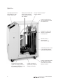
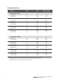
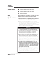
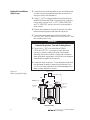
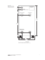
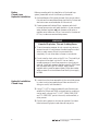
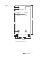
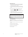
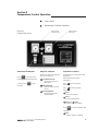
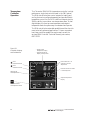
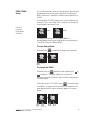
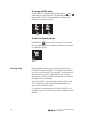
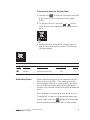
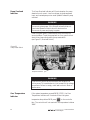
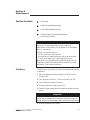
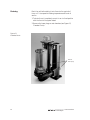
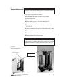
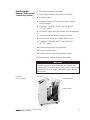
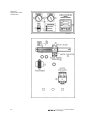
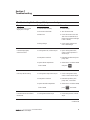
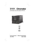
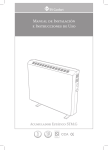
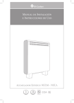
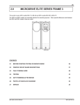
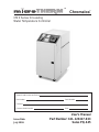
™
®
Chromalox
CMX Series Circulating
Water Temperature Controller
System Model Number and Rating
Part Number
Serial Number
Customer
Customer Order Number
Issue Date
July 1996
Date
User’s Manual
Part Number: 161-123417-023
Sales PQ-445
Table of Contents
Section
Topic
1
Getting Started ........................................................................................... 1
2
Installation .................................................................................................. 5
3
Temperature Control Operation ................................................................ 13
4
System Operation ....................................................................................... 19
5
Diagnostics .................................................................................................. 21
6
Maintenance ............................................................................................... 23
7
Troubleshooting .......................................................................................... 31
8
Specifications.............................................................................................. 33
9
CMX Warranty and Limitation of Remedy and Liability ......................... 37
10
Index ........................................................................................................... 39
™
Page
User Instructions
i
Illustrations
Figure
Topic
1.1
System Photo .............................................................................................. 2
1.2
Control Panel ............................................................................................. 3
2.1
Open-Loop System Piping ......................................................................... 6
2.2
Open-Loop Piping Connections ................................................................ 7
2.3
Closed-Loop System Piping ....................................................................... 9
2.4
Closed-Loop Piping Connections .............................................................. 10
2.5
Power Connection Terminals..................................................................... 11
3.1
Control Panel Layout ................................................................................. 13
3.2
Controller Displays and Pushbuttons......................................................... 14
3.3
Controller PAGE/MENU Selections ......................................................... 15
4.1
Control Panel ............................................................................................. 19
5.1
Diagnostic Indicators .................................................................................. 21
5.2
Pump Reset Switch ..................................................................................... 22
6.1
Chamber Photo .......................................................................................... 24
6.2
Heater/Chamber Photo .............................................................................. 25
6.3
Motor Vent Line ......................................................................................... 26
6.4
Heat Exchanger .......................................................................................... 27
6.5
microTHERM™Open and Closed-Loop Electrical Schematic .................. 28
6.6
Replacement Parts Identification .............................................................. 30
8.1
Pump Capacity ........................................................................................... 34
8.2
Controller MENU Settings ........................................................................ 35
ii
Page
™
User Instructions
Section 1
Getting Started
Section Contents
Introduction
System Photo
Model Identification
Important
Read and understand all instructions in this user’s manual and
the enclosed 2104 temperature control instruction manual
before attempting to install or operate system.
Congratulations on purchasing the Chromalox CMX Series
microTHERM™ Temperature Control System. This system has
been thoroughly engineered, carefully built, and fully tested to
assure years of service.
Introduction
The CMX can be operated at a maximum temperature of 250°F
at a minimum pressure of 30 psi. Water temperature is
maintained by a microprocessor-based temperature controller
which applies heating and cooling as needed. Heat is applied by
a long-life, Incoloy®-sheathed heater. Cooling is either via
direct injection, in an open loop, or through a closed loop heat
exchanger.
Every system is equipped with an automatic vent that removes
unwanted air from the system during operation, and an ASME
pressure relief valve that is factory-set to 125 psi. A pressure
switch ensures adequate water pressure in the system to help
prevent pump cavitation and steam buildup on the heater
elements, which can shorten the lives of the heater and pump.
The switch is factory-set to 20 psi.
Electrical and hydraulic components are located in distinctly
separate areas in the system to better manage heat buildup and
prevent component damage. The pump housing, heater, and
cooling chambers are single cast pieces, designed to drastically
reduce the chance of leaks and provide ease of service and
maintenance. Standard casters make it easy to move the system
from machine to machine.
Power requirements for the system are 240 or 480 volts, 3 phase,
60 cycle, and 4.5 to 24 kW. See the system nameplate for the
appropriate voltage and wattage ratings.
The System Photo and Control Panel Illustrations, on the
following pages, show the CMX and identifies all key
components.
™
User Instructions
1
Figure 1.1
System Photo
Operating temperatures of
50° to 250°F for a wide
variety of applications
ASME pressure relief valve
opens if system pressure
exceeds 125 psi, ensuring
safe operation
Incoloy® sheath Chromalox®
heating elements.
Integral solenoid valve for
precise temperature control
and optimum flow.
Automatic air purge cycle
removes accumulated air
from water lines.
Standard 3.8 sq. ft.
heat exchanger
(closed loop cooling)
Cabinet design allows access
to all components without
removing a single fastener.
Low pressure switch disables
system when supply pressure is
low, preventing cavitation in pump
and protecting the system.
2
Custom cast pump for
optimum flow, minimum
leakage and long life.
Compact, rugged cabinet fits
into tight spaces. Rolling
casters allow easy transfer
between locations.
™
User Instructions
Figure 1.2
Control Panel
Dual pressure gauges for
monitoring of both to process
and from process pressures.
Diagnostic Indicators
Pump
START/STOP
Pushbuttons
™
User Instructions
Chromalox’s 2104 Temperature
and Process Controller
3
Ordering Information
Model
KW
Volts
Total Amperage
Open-Loop Cooling
CMX-250-4
CMX-250-4
4.5
4.5
240
480
13.6
6.8
CMX-250-9
CMX-250-9
9
9
240
480
24.5
12.2
CMX-250-12
CMX-250-12
12
12
240
480
31.7
15.8
CMX-250-18
18
240
46.1
CMX-250-18
18
480
23.1
CMX-250-24
CMX-250-24
24
24
240
480
60.5
30.3
Closed-Loop Cooling
CMX-250-4C
CMX-250-4C
4.5
4.5
240
480
13.6
6.8
CMX-250-9C
CMX-250-9C
9
9
240
480
24.5
12.2
CMX-250-12C
CMX-250-12C
12
12
240
480
31.7
15.8
CMX-250-18C
CMX-250-18C
18
18
240
480
46.1
23.1
CMX-250-24C
CMX-250-24C
24
24
240
480
60.5
30.3
• All voltages are 3 phase. 120V control transformer provided with each unit for control power.
-C: Suffix indicates 3.8 sq. ft. heat exchanger for cooling. All systems equipped with 30 GPM 20 psi. TDH pump standard.
Optional Pump flows up to 80 GPM and 70 psi. TDH available.
4
™
User Instructions
Section 2
Installation
Hydraulic Installation Open-Loop Cooling
Section Contents
Hydraulic Installation Closed-Loop Cooling
Electrical Installation
Before
Open-Loop
Hydraulic Installation
Before proceeding with the installation of the open-loop system,
please take note of the following important information:
1. Reduced diameter fittings may be used if they do not reduce
flow rate and increase pressure drop significantly. Galvanized
steel unions are recommended at all connections.
2. If water pressure falls below 20 psi, a pressure switch will
interrupt pump motor and heater operation. Use an external
water pressure regulator and back pressure relief valve or
regulator set at maximum 125 psi, connected in the external
fill line, to reduce excessive water pressure.
WARNING
Hazard of Explosion, Fire and Scalding Burns
1. The water feed line on both open and closed loop systems
must not have any obstructions which could prevent
expanding water from backing up into the feed line.
2. Do not use oils or other synthetic heat transfer fluids. This
system is for use with water or ethylene glycol and water
mixture for freeze protection only as the heat transfer fluid.
3. When installing system, allow sufficient room to remove the
heater element and other serviceable items when necessary.
18 inches clearance on sides of unit recommended.
4. If the water source is a potable water source, a back flow
preventer and back pressure relief valve/regulator should be
installed and may be required by local code. Do not install a
check valve only on the fill line. The inability of the system
to flow back into the fill line can lead to excessive pressure.
Back pressure relief is required.
5. To avoid excessive pressures, do not connect any valves or
obstructions which could prevent free discharge from relief
valve in a safe manner. Route line so water drains
completely. Do not allow drain to freeze or corrode shut.
™
User Instructions
5
Hydraulic Installation
Open-Loop
1. Locate the unit as close as possible to the controlled process
in order to minimize pressure drops. Make sure the unit is
sitting on a solid, level foundation.
2. Using 1 1/4" NPT or larger schedule 40 pipe (flexible hose
suitable for 150 psi and 250°F minimum service conditions
can be used), connect the 1 1/4" NPT “FROM PROCESS”
and “TO PROCESS” ports to the mold, mold manifold, or
other process.
3. Pipe the entire system to minimize air pockets. Provide air
bleed valves at high points and drains at low points.
4. Connect the plant water supply (30 psi to 80 psi) to the
unit’s 1/2" NPT “WATER SUPPLY/COOLING INLET” port
with suitable pipe or hose.
WARNING
Hazard of Explosion, Fire and Scalding Burns
5. Connect the 1/4" NPT port identified as “DRAIN
COOLING OUTLET” to an open or plant drain that
contains no valves or obstructions that could impede
discharge. Review the condition of potential hot water or
steam going down a plant drain. Verify that local codes and
materials are acceptable for this service.
6. Locate floor drain under unit. The air bleed and relief valve
may discharge hot water or steam from the bottom of the
unit. Do not locate materials that could be damaged by hot
water or steam adjacent to the unit.
Figure 2.1
Open-Loop System Piping
Temperature Controller
Cooling
Valve
Drain/Cooling Outlet
(1/4" NPT)
From Process
(1-1/4" NPT)
Auto
AIr
Bleed
Pressure
Relief Valve
Heater
Thermocouple
Probe
To Process
(1-1/4" NPT)
Pump and
Motor
Water Supply/
Cooling Inlet
(1/2" NPT)
Open-Loop Cooling
6
™
User Instructions
Figure 2.2
Open-Loop Cooling
Piping Connections
Chromalox®
1 7/8"
6"
DRAIN/
COOLING OUTLET
FROM PROCESS
TO PROCESS
28 1/2"
12 5/16"
WATER SUPPLY/
COOLING INLET
6"
4"
7"
15"
Rear View
Note: Dimensions are nominal ± 3/8"
™
User Instructions
7
Before
Closed-Loop
Hydraulic Installation
Before proceeding with the installation of the closed-loop
system, please take note of the following information:
1. Reduced diameter fittings may be used if they do not reduce
flow rate and increase pressure drop significantly. Galvanized
steel unions are recommended at all connections.
2. If water pressure falls below 20 psi, a pressure switch will
interrupt pump motor and heater operation. Use an external
water pressure regulator and back pressure relief valve or
regulator set at maximum 125 psi, connected in the external
fill line, to reduce excessive water pressure.
WARNING
Hazard of Explosion, Fire and Scalding Burns
1. To avoid excessive pressures, do not connect any valves or
obstructions which could prevent free discharge from relief
valve in a safe manner. Route line so water drains
completely. Do not allow drain to freeze or corrode shut.
2. Do not install a check valve on the fill line. The inability of
the system to flow back into the fill line can lead to
excessive pressure. If back flow preventer or check valve is
required, install back pressure regulator rated for 250°F water
with a pressure setting of 30 to 80 psi. Back pressure
regulator setting must be approximately 10 psi above water
supply pressure to minimize water flow directly from supply
to drain.
Hydraulic Installation
Closed-Loop
1. Locate the unit as close as possible to the controlled process
in order to minimize pressure drops. Make sure the unit is
sitting on a solid, level foundation.
2. Using 1 1/4" NPT or larger schedule 40 pipe (flexible hose
suitable for 150 psi and 250°F minimum service conditions
can be used), connect the 1 1/4" NPT “FROM PROCESS”
and “TO PROCESS” ports to the mold, mold manifold, or
other process.
3. Pipe the entire system to minimize air pockets. Provide air
bleed valves at high points and drains at low points.
8
™
User Instructions
Hydraulic Installation
Closed-Loop
(continued)
4. Connect the cooling water supply (30 psi to 80 psi) to the
unit’s 1/2" NPT “WATER SUPPLY/COOLING INLET” port
with suitable pipe or hose.
5. Connect the 1/4" NPT port identified as “COOLING
OUTLET” to a cooling water return line or plant drain that
contains no valves or obstructions that could impede
discharge. Review the condition of potential hot water going
down a plant drain. Verify that local codes and materials are
acceptable for this service. Temperature of discharge water
could reach 250°F and create steam at atmospheric pressure.
Figure 2.3
Closed-Loop System Piping
Cooling Outlet
(1/4 NPT)
Water Supply/
Cooling Inlet
(1/2 NPT)
Solenoid
Valve
Auto
Air
Bleed
Heater
Pressure
Relief Valve
From Process
(1-1/4 NPT)
Thermocouple
Probe
To Process
(1-1/4 NPT)
Pump and
Motor
Closed Loop Cooling
™
User Instructions
9
Figure 2.4
Closed-Loop
Piping Connections
COOLING OUTLET
Chromalox®
1 7/8"
WATER SUPPLY/
COOLING INLET
6"
FROM PROCESS
TO PROCESS
28 1/2"
12 5/16"
6"
4"
7"
15"
Rear View
Note: Dimensions are nominal ± 3/8"
10
™
User Instructions
Electrical
Installation
WARNING
1. Hazard of electric shock. The heat transfer system must be
grounded using grounding means provided in control box
and employing wiring by a qualified electrician in
accordance with National Electric Code. Failure to comply
can result in electrical shock or electrocution.
2. Hazard of electric shock. Disconnect all power before
servicing the heat transfer system. Failure to comply can
result in electrical shock or electrocution.
Fusing or other over-current protection must be supplied to the
system by the user.
The unit is completely wired when shipped. The only wiring
necessary is to the blue colored terminals L1, L2, L3, and the
green-and-yellow colored ground. To make these connections:
Figure 2.5
Power Connection Terminals
1. Loosen the screw on the front electrical enclosure door to
unlock the latch.
2. Open the front electrical enclosure door. Using 90°C wire
sized per National and local codes, run each leg of the three
phase supply power and ground to the appropriate terminals
as shown in Figure 2.5.
3. A separate fused disconnect is required. Locate this fused
disconnect near the equipment. Codes may require the
location of disconnect in sight of operator standing next to
the equipment. Consult applicable codes for details.
Control Voltage fuse
™
User Instructions
11
Pump Rotation Check
4. With power off, check the wiring connections by tugging on
the lines. Tighten all terminals in the control area. These
can loosen due to vibration in shipping.
5. Close the front electrical enclosure door. Pull the top cover
off of the heat transfer system and locate the top of the pump
motor.
6. With the supply water connected, and adequate pressure
present, press the
START
and
STOP
buttons in quick
succession. Watch the rotation on the pump motor to insure
it matches the label on its top.
7. If rotation is incorrect, disconnect power to the system and
swap any two of the supply lines. Repeat rotation check.
WARNING
Close the front electrical enclosure door and retighten the
locking screw. This must be done to limit access to high voltage
components. Failure to comply could lead to electric shock or
electrocution.
Control Voltage Fusing
Terminal block #1 (see Figure 2.5) contains a 120V fuse for the
control circuitry. This fuse protects the control transformer and
circuitry.
1. Should the fuse blow, an indicator will light on the terminal
block.
2. Disconnect power from the system.
3. Determine the cause of the blown fuse.
4. Replace with an equivalent fuse.
5. Reconnect power.
12
™
User Instructions
Section 3
Temperature Control Operation
Control Panel
Temperature Controller Operation
Figure 3.1
Control Panel Layout
START/STOP Pushbuttons
Press
START
to start the pump.
Indicator will illuminate while pump
is running. Press STOP
Outlet Pressure
“To Process”
Inlet Pressure
“From Process”
to stop
the pump.
Diagnostic Indicators
Temperature Controller
System shuts down if any diagnostic
indicator is illuminated.
Top Display reads current system outlet
temperature.
Low Water Pressure:
• System water pressure is
below 20 psi.
Bottom Display reads setpoint
temperature.
Pump Overload:
• Pump has drawn too much
current.
temperature.
Over Temperature:
• System temperature has
exceeded 260°F.
Press
▲
to increase setpoint
Press ▼ to decrease setpoint
temperature.
OUT 1
• Heat is being applied.
OUT 2
• Cooling is being applied.
OUT 3 and
OUT 4
• Indicates overtemp condition
Press RESET to continue operation after
overtemp.
AUX
• Indicates system is in Standby.
™
User Instructions
13
Temperature
Controller
Operation
The Chromalox 2104 1/4 DIN temperature controller is a highperformance, single-loop controller used in the CMX system.
The 2104 controller has two control outputs for heating and
cooling that can be configured separately and provide flexible
temperature control for the CMX. Additional outputs give the
2104 the ability to provide an over-temperature alarm. A dual
digital display of current process temperature and setpoint
temperature make the system easy to understand and operate.
The 2104 controller has extended capabilities and functions for
more technically advanced applications. To learn more about
how these controller capabilities may be used, consult the
enclosed 2104 Controller Technical Manual, part number,
0037-75276.
Figure 3.2
Controller Displays
and Pushbuttons
OUT 1
• Indicates Heat ON
• System Outlet
Temperature Display
• Alphanumeric Menu
Display in Setup Mode
LEDs indicate °F or °C
selected for Process
Temperature
OUT 2
• Indicates Cool ON
LEDs indicate
Overtemperature
LED indicates the controller
is in Standby mode
Setpoint Temperature
Display
RESET
Pushbutton Resets
Overtemperature Alarm
14
™
User Instructions
All control parameters, selections and calibration procedures for
the temperature controller are accomplished through simple
MENU selections. These MENU selections are organized into
PAGES.
PAGE/MENU
Setup
The Display PAGE (DISP) allows you to view the status of the
controller. The Control Page (CTRL) allows you to change the
control setpoint and security lock.
Figure 3.3
Controller
PAGE/MENU
Selections
DISP
C TRL
Display
P A GE
RESET
▲
AUX
Control
P A GE
▼
RESET
AUX
▲
▼
Accessing the Security Lock or Setpoint MENU is
accomplished by entering the Setup Mode, then selecting the
Control PAGE and the desired MENU.
To enter Setup Mode:
Hold down the
250
☛
▲
AUX
▼
123
RESET
Hold for at least
3 seconds.
pushbutton for longer than 3 seconds.
L OC
H
OCH
➮
250
RESET
RESET
AUX
▲
▼
Setup Mode entered.
To change the PAGE:
Press and hold the
RESET
pushbutton while pressing the ▲ or
▼ pushbutton. The upper display will increment (or
decrement) through the PAGEs, and PAGE will be displayed in
the lower display.
After reaching the CTRL PAGE, press
RESET
to move through
the MENUs. The alpha cue for the MENU will appear on the
upper display, and the current value will appear in the lower
display.
➮
▲
☛
AUX
Hold
™
▼
P A GE
☛
☛
250
RESET
C TRL
☛
SP
RESET
AUX
▲
▼
Press ▲ or ▼
User Instructions
15
To change a MENU value:
After the MENU is selected and displayed, use the ▲ and ▼
pushbuttons to change the value. For large adjustments (for
example, 100 to 200), hold the pushbutton pressed and the
display will change more quickly.
➮
☛
100
RESET
AUX
▲
SP
▼
200
RESET
☛
SP
AUX
▲
▼
To return to Operating Mode:
Press and hold
RESET
for more than 3 seconds. The controller
will automatically return to operating mode after 10 minutes of
no pushbutton activity.
STB
Y
STBY
☛
101
RESET
AUX
▲
▼
Hold for at least
3 seconds.
Security Code
Every parameter or selection in the 2104 controller’s setup
PAGEs has an identifying MENU. The MENUs are accessible
only if the correct Security Code is entered. This allows you to
set the Security level that is appropriate for your operating
environment, prohibiting unauthorized access to or accidental
changing of control parameters.
The microTHERM™ system is factory preset to security code
123. To adjust any of the controller’s setup parameters, the
security code must be set to 458.
The Security Code is entered on the Control PAGE CTRL, at
the MENU LOCH. This code determines which MENUs may be
adjusted.
16
™
User Instructions
To access and enter the Security Code:
1. Press and hold
RESET
for more than 3 seconds to enter Setup
Mode. Security Lock is the first menu that will appear
(LOCH).
2. To change the Security Code, press ▲ or ▼ until the
correct security code is displayed (458 to change controller
setup).
L OC
H
OCH
☛
123
RESET
AUX
▲
▼
3. Reference the factory preset MENU settings (Figure 8.2,
page 35), when replacing the controller or if the settings
have been changed.
C TRL
P A GE
RESET
AUX
▲
▼
Control Page
Menu
Description
Available Settings
LOC
H
OCH
Security Lock
SP
Setpoint
Alarm Relay Action
Factory Settings
Security
0 to 9999
123
A
Instrument sensor span
32°F
B
Output relays #3 and #4 are set as over-temperature latching
alarms. If the microTHERM™ CMX system encounters an
over-temperature condition (in excess of 260°F), both alarms
will trip, disabling the system. Output #3 provides operator
indication of an overtemp condition and Output #4 disables the
system.
Do not change any of the settings for either output #3 or #4.
The system will not reset until the process temperature drops
below the alarm value. The
RESET
pushbutton must be pressed
and the temperature must be below 260°F in order to restart.
™
User Instructions
17
Notes
18
™
User Instructions
Section 4
System Operation
WARNING
On both open and closed-loop systems, turn on water and
insure the water supply lines are free of obstructions BEFORE
energizing the heater. Such obstructions could prevent the
thermal expansion of water from backing up into this line,
thereby increasing system pressure until the relief valve opens.
Note:
This system is equipped with an ASME safety pressure relief
valve (factory preset at 125 psi).
1. Apply power to the system via the remote disconnect. The
temperature controller and “LOW WATER PRESSURE”
diagnostic light should illuminate.
2. Open supply-water line and process valving to allow system
to fill. Auto air bleed will remove air from the system. Any
remote air bleed valves should be opened to remove air
from process and associated piping.
3. “LOW WATER PRESSURE” diagnostic light should go out
when the system is filled and has reached 20 psi. The system
will not start when light is illuminated.
4. Adjust the temperature setpoint to the desired level via the
controller front panel arrow keys (see page 15). For
complete details on operation of temperature control,
consult the separate 2104 Technical Manual
(P/N 0037-75276) included with the unit.
Figure 4.1
System Operation
1. Low Water Pressure Indicator
will light when power is first
applied. Indicator will go out
when system is filled and
reaches 20 psi.
3. Press
START
to start
the pump.
2. Adjust the temperature setpoint
to desired level.
™
User Instructions
19
5. Assure that Pump Rotation Check was performed per
instructions on page 12.
6. Start the pump by pressing
START
on the front panel. The
pump indicator light will illuminate.
7. Once temperature has stabilized at the setpoint level,
review controllability of the system. If the temperature
(displayed in the top display of the temperature controller)
is fluctuating at an unacceptable level, consult the
temperature control instruction manual for details on
tuning the controller. Heat and cooling action is indicated
via the L.E.D.’s on the left side of the controller (OUT 1 for
heat, OUT 2 for cooling).
8. If the system temperature is below the current setpoint, heat
will be applied by the controller to the heater elements. If
the temperature is above the setpoint, the cooling solenoid
will open (open and closed loop) to reduce the system
temperature.
WARNING
Operating systems at temperatures above 140°F will create
surface temperatures on pipes that can cause burns. Precautions
should be taken to prevent operator contact with hot pipes.
Also, bleed valves should be locked down to prevent release of
hot fluid.
☛
Note:
This is a PID type controller and cycling of the heat and cool
can be expected below and above setpoint.
9. For system shutdown, lower the setpoint to 90°F or lower
(see pages 15-17). Allow the system to cool to this
temperature level.
10. Press
STOP
to de-energize the pump and disable the
system.
11. Disconnect power to the unit.
WARNING
Do not leave system unattended in a HOT electrical condition;
and do not leave system unattended in HOT environmental
conditions.
20
™
User Instructions
Section 5
Diagnostics
Lower Water Pressure
Section Contents
Pump Overload
Over Temperature
Figure 5.1
Diagnostic Indicators
Diagnostic Functions
All diagnostic functions will shut down the system and require
the operator to remedy the problem before it can be restarted.
Low Water
Pressure Indicator
The pump, heater, and cooling will not operate while the
pressure is low. The Low Water Pressure Indicator will
illuminate when the system pressure is below 20 psi. This
warning system is designed to reduce the possibility of pump
cavitation and boiling on the heater element at higher
operating temperatures.
™
User Instructions
21
Pump Overload
Indicator
The Pump Overload Indicator will illuminate when the pump
draws too much current. Low line voltage, single phase power
input, and a seized pump motor are all possible causes for pump
overload.
WARNING
Disconnect system power, if the Pump Overload Indicator is
illuminated. Hazard of electric shock or electrocution.
Disconnect all power and piping to system.
After the system power is disconnected, solve the electrical
current problem. To put the pump back on-line, open the front
electrical enclosure and press the pump reset switch
(see Figure 5.2, Overload Switch).
Figure 5.2
Pump Reset Switch
Pump Reset Switch
WARNING
Close the front electrical enclosure door and retighten the
locking screw. This must be done to limit access to high voltage
components. Failure to comply could lead to electric shock or
electrocution.
Over Temperature
Indicator
If the system temperature exceeds 260°F (127°C), the Over
Temperature Indicator will illuminate. When the system
temperature drops below 260°F, press
RESET
on the controller
face. The controller will not reset until the temperature is below
260°F.
22
™
User Instructions
Section 6
Maintenance
Section Contents
Shut Down
Heater Removal/Replacement
Pump Removal/Replacement
Heat Exchanger Removal/Replacement
(closed loop systems)
WARNING
Disconnect all power before servicing or performing
maintenance to the system. Do not attempt to service system
while it is operating.
Failure to comply can result in:
a. Electrical shock or electrocution.
b. Burns from hot heating elements, piping, and hot water.
c. Injury from operating or rotating pump and motor.
Maintenance is to be performed by qualified personnel only.
Thoroughly read and understand these instructions. Consult
the factory if you have any questions.
To take the unit out of service, the following steps must be done
in sequence:
Shut Down
1. Set the temperature controller setpoint to 90°F or lower.
Allow to cool.
2. Turn off power to the unit. The controller will turn off.
3. Turn off the water supply to the unit.
4. Disconnect electrical supply to the unit.
5. Carefully bleed pressure from the system by loosening a pipe
fitting.
WARNING
System may be pressurized. Use extreme care while removing
piping. Disconnect water supply, drain and process connections.
6. Drain all water from the system.
™
User Instructions
23
Draining
Drain the unit before taking it out of service for a period of
time, or if it is exposed to freezing temperatures while out of
service.
1. To drain the unit completely, move it to an inclined position
with the front of the system raised.
2. Remove the lower plugs on cast chambers (see Figure 6.1,
Chamber Photo).
Figure 6.1
Chamber Photo
Remove
these plugs
24
™
User Instructions
Heater
Removal/Replacement
WARNING
Hazard of electric shock or electrocution. Disconnect all power
and piping to system.
1. Disconnect all power to the system.
2. Bleed pressure and drain all water from the system.
3. Remove top panel.
4. Remove red top cover on the heater (see Figure 6.2,
Heater/Chamber Photo).
5. Note location of wires on the heater, then remove wires
(L1, L2, L3).
6. Loosen compression fitting on the heater power supply cable.
7. Remove cable from the heater.
8. Unbolt the heater (4 bolts) and remove.
9. Replace heater and reverse procedure.
WARNING
Close the front electrical enclosure door and retighten the
locking screw. This must be done to limit access to high voltage
components. Failure to comply could lead to electric shock or
electrocution.
Figure 6.2
Heater/Chamber Photo
Remove Top Panel
Remove Top Cover
on Heater
™
User Instructions
25
WARNING
Hazard of electric shock or electrocution. Disconnect all power
and piping to system.
Pump
Removal/Replacement
1. Disconnect all power to the system.
2. Bleed pressure and drain all water from the system.
3. Remove top and side panels.
4. Remove pump motor wiring cover panel (2 screws).
5. Note location of pump motor wires and remove.
6. Loosen and remove vent line
(see Figure 6.3, Motor Vent Line).
7. Remove bolts holding pump motor to the casting (4 bolts),
and lift motor out of casting.
8. Remove impeller and install new mechanical seal and
impeller on the new motor.
9. Place new motor in system and bolt down.
10. Replace vent line and tighten.
11. Reconnect wires and replace wiring cover and side panels.
12. Reconnect the system.
13. Perform Pump Rotation Check (see Section 2, page 12).
14. Replace top panel.
WARNING
Close the front electrical enclosure door and retighten the
locking screw. This must be done to limit access to high voltage
components. Failure to comply could lead to electric shock or
electrocution.
Figure 6.3
Motor Vent Line
Motor
Heater Element
Housing
Pump Housing
Pump/Motor Vent Line
26
™
User Instructions
Heat Exchanger
Removal/Replacement
(closed loop system)
1. Disconnect all power to the system.
2. Bleed pressure and drain all water from the system.
3. Remove top panel.
4. Remove cover on the cooling solenoid (see Figure 6.4,
Heat Exchanger).
5. Disconnect “COOLING INLET” and “COOLING
OUTLET” piping.
6. Disconnect copper tubing connected to the heat exchanger.
7. Unbolt the heat exchanger and remove (4 bolts).
8. Place new heat exchanger in system and bolt down.
9
Reconnect “COOLING INLET” and “COOLING
OUTLET” piping.
10. Reconnect wires to the cooling solenoid.
11. Reconnect copper tubing.
12. Replace cover on cooling solenoid and top panel.
13. Replace system water and reconnect the system.
WARNING
Close the front electrical enclosure door and retighten the
locking screw. This must be done to limit access to high voltage
components. Failure to comply could lead to electric shock or
electrocution.
Top Panel
Figure 6.4
Heat Exchanger
Cooling Solenoid
Heat Exchanger
™
User Instructions
27
Figure 6.5
microTHERM™ Open and Closed-Loop Electrical Schematic
1C
L1
1L1
1T1
L2
1L2
1T2
L3
1L3
1T3
Customer Supplied
Voltage
1M-1
GND.
3T1
3T3
2L1
2T1
2L2
2T2
2L3
2T3
Pump
Contactor
Optional
Door Interlock
5
Pump
Motor
Pump
Overload
120V
DI-1
1
Heater
4.5 KW to 24 KW
OL
Fuse
2
1F
1
Low
Pressure
Pressure
Switch
3
4
R
1PS
Low
Pressure
Indication
Pump
ON
Start
Stop
6
5
11
7
12 13
95
14
W
X1
OL
95
1M
A2
X2
A1
Pump
Motor
Control
1M-1
Output #4
13
1M-2-1
8
1ITC
1M-2-2
61
62
Type J
T/C
Heater
Contactor
14
16
9
53
1
2
19
20
10
11
3
21
12
4
5
22
23
13
14
6
7
24
25
15
16
8 +
9 -
26
27
17
18
1C
54
Heater
Control
Output #1
Output #2
Cooling
Solenoid
10
Cooling
Control
Heater
Overtemp
11
Output #3
R
Pump
Overload
OL-1
12
98
28
R
97
™
Overtemp
Indication
Pump
Overload
Indication
User Instructions
Replacement Heating Elements and Contactors
Replacement Parts
Model
Open Loop
Closed Loop
Voltage
CMX-4
CMX-4C
CMX-9
CMX-9C
CMX-12
CMX-12C
CMX-18
CMX-18C
CMX-24
CMX-24C
240
480
240
480
240
480
240
480
240
480
Heating Element
Heater Contactor
155-554807-523
155-554807-523
155-554807-512
155-554807-512
155-554807-524
155-554807-524
155-554807-519
155-554807-519
155-554807-515
155-554807-515
072-057576-050
072-057576-050
072-057576-050
072-057576-050
072-057576-050
072-057576-050
072-057576-051
072-057576-050
072-057576-051
072-057576-050
Replacement Parts Common to All Models
Identification #
Part Name
Part #
1 .............................. 3/4 HP Motor 240V/480V ............................................. 193-121843-227
2 .............................. Solenoid Valve (Open Loop) ....................................... 344-121780-012
2 .............................. Solenoid Valve (Closed Loop) .................................... 344-121780-002
3 .............................. Pressure Relief Valve ..................................................... 344-048419-004
4 .............................. Automatic Air Vent ......................................................... 344-053181-001
5 .............................. Pressure Gauge ............................................................... 130-118661-021
6 .............................. Pressure Switch ............................................................... 292-121927-028
7 .............................. Pump Mechanical Seal ................................................. 251-121946-019
8 .............................. Heat Exchanger Bundle (Closed Loop) .................. 353-123367-002
9 .............................. Heater/Cooling Gasket (2 total) ................................ 132-146012-020
10 .............................. Thermocouple ................................................................... 309-121759-063
11 .............................. Temperature Controller ................................................. 300-123617-001
12 .............................. Switch, Start/Stop ........................................................... 292-122882-043
12 .............................. Switch Indicator Bulb .................................................... 213-122066-034
13 .............................. Diagnostic Indicator Light (3 total) .......................... 213-122066-041
14 .............................. Motor Contactor 240/480V ......................................... 072-123534-001
15 .............................. Auxiliary Motor Contact Block ................................... 071-122886-033
16 .............................. Motor Thermal Overload 240V ................................... 359-122078-062
16 .............................. Motor Thermal Overload 480V .................................. 359-122078-061
17 .............................. Transformer 240/480V ................................................... 315-303786-001
18 .............................. Caster (4 total) ................................................................. 375-123425-003
19 .............................. Control Voltage Fuse...................................................... 128-123445-005
20 .............................. Heater Contactor ............................................................. See table above
™
User Instructions
29
Figure 6.6
Replacement Parts
Identification
19
30
™
User Instructions
Section 7
Troubleshooting
Troubleshooting Guide—For qualified personnel only
Symptom
Probable Cause
Correction
Unit will not start, control
display does not light.
1. Unit not wired correctly.
1. Check wiring.
2. Disconnect switch OFF.
2. Turn disconnect ON.
3. Blown fuse.
3. Check disconnect fuses and
120V fuse on terminal block
(blown fuse indicator will light
if fuse is blown).
4. Wrong voltage.
4. Check supply voltage and
unit’s rated voltage.
1. Cooling water off, or below 20 psi.
1. Open cooling water valve,
check to assure pressure is
above 30 psi.
2. Pump motor overload.
2. Determine problem and press
pump reset.
3. System above temperature
3. Allow unit to cool below 260°F
Control display lights,
unit will not start.
limit of 260°F.
Unit stops while running.
RESET
.
1. Cooling water drops below 20 psi.
1. Check cooling water valve,
check to assure above 30 psi.
2. Pump motor overload.
2. Determine problem, press
pump reset , and restart.
3. System exceeds temperature
3. Allow unit to cool below 260°F,
limit of 260°F.
Low Water Pressure Indicator
illuminated.
and press
1. Cooling water below 20 psi.
press
RESET
, and restart.
1. Check that pressure is above
30 psi.
continued ➔
™
User Instructions
31
Troubleshooting Guide—For qualified personnel only
Symptom
Probable Cause
Correction
Pump Overload Indicator
illuminated.
1. Pump motor overload.
1. Determine problem and press
pump reset button.
Over Temperature Indicator
1. System above temperature limit
1. Allow unit to cool below 260°F
illuminated.
of 260°F.
and press
RESET
.
Unit runs but fails to pump
water.
1. Incoming phase reversed on
pump motor.
1. Swap any two legs on the
incoming power.
Unit will not heat to setpoint.
1. Cooling valve stuck open.
1. Check for cooling water flow
during heat cycle.
2. Heater element failure.
2. Check current at heater
contactor during heating.
3. Heater output insufficient.
3. Excessive losses in process or
incorrectly sized unit for
application.
4. Controller needs to be tuned.
4. Check factory MENU settings,
page 35 of this manual.
Refer to 2104 Controller
Technical Manual, page 35,
for further information.
1. Inadequate cooling water flow.
1. Open cooling water supply
line more and assure
adequate pressure.
2. Cooling outlet obstructed.
2. Check cooling outlet for
obstructions.
3. Heater contactor fused closed.
3. Check voltage across
contactor during cooling cycle.
4. Controller needs to be tuned.
4. Check factory MENU settings,
page 35 of this manual.
Refer to 2104 Controller
Technical Manual, page 35,
for further information.
Unit will not cool to setpoint.
If you continue to have problems with the system after review of the above issues, please contact
Chromalox Product Service at 800-368-2493 from 6 A.M. to 6 P.M. MST.
32
™
User Instructions
Section 8
Specifications
Standard 3/4 HP Pump
Pump
Size
(HP)
3/4
Nominal
Flow
(gpm)
Heating
Capacity
(kW)
Standard
Voltages
4.5
240 or 480
9
240 or 480
12
240 or 480
18
240 or 480
24
240 or 480
30
Optional Pump Sizes
™
User Instructions
Process
Connections
(inches dia.)
Drain/supply
(inches dia.)
Approximate
Dimensions
(inches)
29 height
1 1/4 NPT
1/4 NPT
25 depth
15 width
Optional
Pump Sizes
(HP)
Nominal
Flow
(gpm)
1.5
40
3
50
5
60
7.5
80
33
Other Options
• Alternate Voltages: 208, 380, 575 VAC, 3 phase
• Expanded Open Loop Cooling: increased cooling water flow
• Expanded Closed Loop Cooling: 6.3 sq. ft. heat exchanger
• Solid State Power Control: SCR heater switching
• Surge Reduction valve: reduces water pressure spikes
• Door Interlock: prevents operation with service door open
• Digital Communications: for interface with ChromaSoft or
remote PC/PLC systems
• IEC Style Contactor: for dry contact power switching
• Isolation Valve Kit: 1" ball valves for system isolation
Figure 8.1
Pump Capacity
Five pump sizes are available for the flow rate
appropriate to your process application.
PSI Ft.
78 180
69
160
61
140
52
120
43
100
35
80
26
60
17
40
9
20
7.5 HP
5 HP
3 HP
1.5 HP
3/4 HP
0
20
40
60
80
U.S. Gallons Per Minute
100
120
Pump Capacity
34
™
User Instructions
Figure 8.2
Controller MENU Settings
™
User Instructions
35
Notes
36
™
User Instructions
Section 9
CMX Warranty and Limitation of Remedy and Liability
Warranty
Chromalox warrants only that the Products and parts
manufactured by Chromalox, when shipped, and the work
performed by Chromalox when performed, will meet all
applicable specification and other specific product and work
requirements (including those of performance), if any, and will
be free from defects in material and workmanship under normal
conditions of use. All claims for defective or nonconforming
(both hereinafter called defective) Products, parts or work
under this warranty must be made in writing immediately upon
discovery, and in any event, within one (1) year from delivery,
provided, however all claims for defective Products and parts
must be made in writing no later than eighteen (18) months
after shipment by Chromalox. The temperature controller,
heater and pump/chamber castings warranty is extended to
three (3) years from date of shipment. Defective and
nonconforming items must be held for Chromalox’s inspections
and returned to the original f.o.b. point upon request. THE
FOREGOING IS EXPRESSLY IN LIEU OF ALL OTHER
WARRANTIES WHATSOEVER, EXPRESS, IMPLIED AND
STATUTORY, INCLUDING, WITHOUT LIMITATION,
THE IMPLIED WARRANTIES OF MERCHANTABILITY
AND FITNESS FOR A PARTICULAR PURPOSE.
Limitation of Liability
Notwithstanding the provisions of this WARRANTY AND
LIMITATION Clause, it is specifically understood that Products
and parts not manufactured and work not performed by
Chromalox are warranted only to the extent and in the manner
that the same are warranted to Chromalox by Chromalox’s
vendors, and then only to the extent that Chromalox is
reasonably able to enforce such warranty, it being understood
Chromalox shall have no obligation to initiate litigation unless
Buyer undertakes to pay all cost and expenses therefor,
including but not limited to attorney’s fees, and indemnifies
Chromalox against any liability to Chromalox’s vendors arising
out of such litigation.
™
User Instructions
37
Limitation of Remedy
Upon Buyer’s submission of a claim as provided above and its
substantiation, Chromalox shall at its option either (i) repair or
replace its Products, parts or work at the original f.o.b. point of
delivery or (ii) refund an equitable portion of the purchase
price.
THE FOREGOING IS CHROMALOX’S ONLY
OBLIGATION AND BUYER’S EXCLUSIVE REMEDY FOR
BREACH OF WARRANTY, AND IS BUYER’S EXCLUSIVE
REMEDY AGAINST CHROMALOX FOR ALL CLAIMS
ARISING HEREUNDER OR RELATING HERETO
WHETHER SUCH CLAIMS ARE BASED ON BREACH OF
CONTRACT, TORT (INCLUDING NEGLIGENCE AND
STRICT LIABILITY) OR OTHER THEORIES, BUYER’S
FAILURE TO SUBMIT A CLAIM AS PROVIDED ABOVE
SHALL SPECIFICALLY WAIVE ALL CLAIMS FOR
DAMAGES OR OTHER RELIEF, INCLUDING BUT NOT
LIMITED TO CLAIMS BASED ON LATENT DEFECTS. IN
NO EVENT SHALL BUYER BE ENTITLED TO
INCIDENTAL OR CONSEQUENTIAL DAMAGES AND
BUYER SHALL HOLD CHROMALOX HARMLESS
THEREFROM. ANY ACTION BY BUYER ARISING
HEREUNDER OR RELATING HERETO, WHETHER
BASED ON BREACH OF CONTRACT, TORT
(INCLUDING NEGLIGENCE AND STRICT LIABILITY)
OR OTHER THEORIES, MUST BE COMMENCED
WITHIN ONE (1) YEAR AFTER THE DATE OF
SHIPMENT OR IT SHALL BE BARRED.
38
™
User Instructions
Section 10
Index
Alarm
Incoloy-sheathed heater 1, 2
•latching 17
•Overtemperature 13, 14, 17
•Relay Action 17
Cabinet 2
Cavitation 2, 21
Closed-loop Heat Exchanger 1
Control Output #1 (Heat) 13, 14, 28
Control Output #2 (Cool) 13, 14, 28
Control Setpoint 13, 14, 15
Control Voltage Fusing 11, 12
Controller
•Temperature Controller 3, 9, 13, 14, 19,
23, 29
Cooling Chamber 1
Cooling Control 28
Cooling Solenoid 20, 27, 28
Cooling Water Valve 31, 32
Diagnostic Functions 13, 21
Diagnostic Indicators 3, 13, 19, 21, 28, 29
•Low Water Pressure 3, 13, 19, 21, 28
•Over Temperature 3, 13, 19, 21, 22, 28
•Pump Overload 3, 13, 19, 21, 22, 28
Draining 24
Electrical Installation 11
Fusing 11, 12, 31
•Control Voltage 11, 12
Heat Exchanger 2, 27
•closed-loop 1, 2
•open-loop 1
•Removal/Replacement 27
™
User Instructions
Indicators
•Diagnostic 3, 13, 19, 21
•Low Pressure 3, 13, 19, 21, 28
•Overtemp 3, 13, 19, 21, 22, 28
•Pump Overload 3, 13, 19, 21, 22, 28
Low Pressure Switch 2
MENU selections 13-16
•Control PAGE 15
•Display PAGE 15
MENU value 16
Motor 30, 31-32
Motor Contactor 29
Motor Control 26, 28, 29
Motor Vent Line 26
Open-Loop Heat Exchanger 1
Operating Mode 16
Operating Temperature 1, 2
Output Relay #3 17, 28
Output Relay #4 17, 28
Overtemperature Indicator 13, 21, 22, 28, 31
Power requirements 1
Pressure gauges 3, 13, 19, 29
Pressure Indicator
•Low water 13, 19, 21
Pressure Relief Valve 1, 2, 5, 6, 8, 9, 19
Process Temperature 13, 14
Pump 2, 6, 8, 9, 21, 24, 26, 28-32
•Pump Indicator Light 18
•Removal/Replacement 26
•Rotation Check 10, 18, 26
Pump Cavitation 2, 21
Pump Housing 1, 2, 6, 9, 24, 25, 26, 27
Pump Motor 5, 6, 8, 9, 20, 21, 24-29, 31-32
•wires 24
Pump Reset Switch 22
39
Replacement Heating Elements and
Contactors 29
Replacement Parts 29
Security Code 16
•Access 17
•Change 17
Security Lock 15
Setpoint 13, 14, 15, 19, 20
•Change 15
•Control 15
•Temperature 14, 19
Setup Mode 15
Shutdown 20, 21, 23
Solenoid Valve 2, 9, 28
Specifications 33
Switch
•Low Pressure 2
•Pressure 1, 5
•Pump Reset 22
Valve
•check 5, 7
•cooling 6, 31-32
•pressure relief 1, 2, 5, 6, 8, 9, 19
•solenoid 2, 9, 28
Vent
•automatic 1
•vent line 26
Water Pressure 5, 6
•diagnostic light 3, 13, 19, 21
•regulator 5, 6
Water Temperature 1
40
™
User Instructions
Chromalox®
701 Alpha Drive
Pittsburgh, PA 15238
PHONE (412) 967-3800
FAX (412) 967-5148
®
96-082
PQ-445
July 96