1
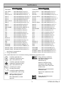
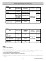
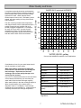
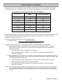
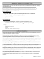
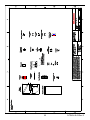
Hot Water System
Design Manual
Plumbing schematics for single
and multiple Rinnai tankless
water heaters in use with
domestic systems, recirculation,
and storage tanks.
Table of Contents
Certifications................................................................ 3, 4
Non-condensing Water Heaters
Rinnai Accessories ......................................................... 4
Drawing
MSB Kits for Connecting Multiple Water Heaters ........ 5
WH1
1
Basic Piping................................... 29
Model Applicability .......................................................... 6
WH2
2
Basic Piping................................... 30
Water Quality and Scale ................................................. 7
WH3
3
Basic Piping................................... 31
Pump Sizing for Circulation ........................................... 8
WH6
6
Basic Piping................................... 32
Tank Water Heaters in a Circulation Loop .................... 9
WH1-D
1
Freeze Protection .......................... 33
Additional Guidelines ..................................................... 9
WH2-D
2
Freeze Protection .......................... 34
Vent Termination Clearances ....................................... 10
WH3-D
3
Freeze Protection .......................... 35
Additional Clearances ................................................... 12
WH6-D
6
Freeze Protection .......................... 36
Pump Sizing for Storage Tank Applications .............. 14
WH1-RGE
1
Optional Recirculation ................... 37
Pressure Loss Curves - Non Condensing Models ..... 15
WH1-R
1
Optional Recirculation ................... 38
Pressure Loss Curves - Condensing Models ............. 16
WH1-CD-O
1
Preferred Demand Circulation....... 39
WH1-CD
1
Preferred Demand Circulation....... 40
Condensing Water Heaters
WH2-CP
2
Circulation System ........................ 41
Drawing
WH3-CP
3
Circulation System ........................ 42
No. Description
No. Description
CWH1
1
Basic Piping ................................... 17
WH6-CP
6
Circulation System ........................ 43
CWH2
2
Basic Piping ................................... 18
WH1-BC
1
Backup Storage ............................. 44
CWH3
3
Basic Piping ................................... 19
WH2-BC
2
Backup Storage ............................. 45
CWH6
6
Basic Piping ................................... 20
WH3-BC
3
Backup Storage ............................. 46
CWH1-C
1
Circulation System ........................ 21
WH6-BC
6
Backup Storage ............................. 47
CWH2-C
2
Circulation System ........................ 22
WH1-AHU
1
Hydronic Furnace .......................... 48
CWH3-C
3
Circulation System ........................ 23
WH1-AHU-RES 1
CWH6-C
6
Circulation System ........................ 24
Hydronic Furnace and
Heat Exchanger............................. 49
CWH1-BC
1
Backup Storage ............................. 25
WH1-A1-CD
1
Demand Circulation with 1 Rinnai
Hydronic Furnace .......................... 50
CWH2-BC
2
Backup Storage ............................. 26
WH2-A1-CD
1
CWH3-BC
3
Backup Storage ............................. 27
Combination System with 2 Rinnai
Hydronic Furnaces ........................ 51
CWH6-BC
6
Backup Storage ............................. 28
WH1-AH
1
Generic Air Handler ....................... 52
WH1-S-1
1
Solar Backup ................................. 53
Maintenance Procedure
WH1-F
1
Flush Procedure ............................ 54
Legend ......................................................................... 55
2
R-TRWH-E-02 Rev D
Certifications
Indoor Water Heaters
Trade Name
CSA Listing
V53i, RV53i........... REU-VB2020FFU-US-(N, P)
R50LSi .................. REU-VA2019FFUD-US-(N, P) *
R75LSi, RL75i ...... REU-VB2528FFUD-US-(N, P) *
R75LSi .................. REU-VA2528FFUD(A)-UC-(N, P) *
R75LSi .................. REU-VA2528FFUD(A)-US-(N, P) *
R75LSi .................. REU-VA2528FFUD-US-(N, P) *
R94LSi, RL94i ...... REU-VB2735FFUD-US-(N, P) *
R94LSi .................. REU-VA2535FFUD-UC-(N, P)*
R94LSi .................. REU-VA2535FFUD-US-(N, P)*
R98LSi .................. REU-VA3237FFU-US-(N, P) *
R98LSiASME........ REU-VA3237FFU-ASME-(N, P) *
R53i ...................... REU-V2520FFU-US-(N, P)
C53i ...................... REU-V2520FFUC-US-(N, P) *
R53i ...................... REU-V2520FFUD-US-(N, P)
C53i ...................... REU-V2520FFUCD-US-(N, P) *
R85i ...................... REU-V2532FFU-US-(N, P)
C85i ...................... REU-V2532FFUC-US-(N, P) *
R85iPLUS ............. REU-V2532FFUD-US-(N, P)
C85iPLUS ............. REU-V2532FFUCD-US-(N, P) *
R98i ...................... REU-V3237FFU-US-(N, P)
C98i ...................... REU-V3237FFUC-US-(N, P) *
R98iASME ............ REU-V3237FFU-ASME-(N, P)
C98iASME ............ REU-V3237FFUC-ASME-(N, P) *
RC80HPi, RC80i .. REU-KA2530FFUD-US-(N, P)*
RC98HPi, RC98i .. REU-KA3237FFUD-US-(N, P)*
*
authorized for commercial use
Energy Star Qualified
Outdoor Water Heaters
Trade Name
CSA Listing
V53e, RV53e...........REU-VAM1620W-US-(N, P)
R63LSe ...................REU-VA2024WD-US-(N, P) *
R63LSe2 .................REU-VA2024WD(A)-UC-(N, P) *
R75LSe, RL75e ......REU-VB2528WD-US-(N, P) *
R75LSe ...................REU-VA2528WD(A)-UC-(N, P) *
R75LSe ...................REU-VA2528WD(A)-US-(N, P) *
R75LSe ...................REU-VA2528WD-US-(N, P) *
R94LSe, RL94e ......REU-VB2735WD-US-(N, P) *
R94LSe ...................REU-VA2535WD-UC-(N, P) *
R94LSe ...................REU-VA2535WD-US-(N, P) *
R98LSe ...................REU-VA3237W-US-(N, P) *
R98LSeASME .........REU-VA3237W-ASME-(N, P) *
R42e .......................REU-V1616W-US-(N, P)
C42e .......................REU-V1616WC-US-(N, P) *
R53e .......................REU-V2020W-US-(N, P)
C53e .......................REU-V2020WC-US-(N, P) *
R70e .......................REU-V2526W-US-(N, P)
R85e .......................REU-V2532W-US-(N, P)
C85e .......................REU-V2532WC-US-(N, P) *
R85ePLUS ..............REU-V2532WD-US-(N, P)
C85ePLUS ..............REU-V2532WCD-US-(N, P) *
R98e .......................REU-V3237W-US-(N, P)
C98e .......................REU-V3237WC-US-(N, P) *
R98eASME .............REU-V3237W-ASME-(N, P)
C98eASME .............REU-V3237WC-ASME-(N, P) *
RC80HPe, RC80e...REU-KA2530WD-US-(N, P)*
RC98HPe, RC98e...REU-KA3237WD-US-(N, P)*
The models listed above have received the following certifications except where noted:
Certified to applicable U.S.
standards for appliances using
gas or other petroleum fuel.
Energy efficiency certified by
Gas Appliance Manufacturers
Association (GAMA),
www.ahrinet.org
Certified to applicable Canadian
standards for appliances using
gas or other petroleum fuel.
Meets the California Energy
Commission (CEC) standards
Meets California and Texas NOX
emission rules
Certified by the Uniform
Plumbing Code (UPC)
Approved by the Commonwealth
of Massachusetts
Certified by National Sanitation
Foundation (NSF), www.nsf.org
Approved for installations in New
York City
(indoor models must use the
NSF approved top guard)
Energy Star Qualified (models
indicated with )
REU-VAM1620W is not NSF
approved
3
R-TRWH-E-02 Rev D
Certifications
R98LSiASME
R98LSeASME
R
R98iASME
C98iASME
R98eASME
C98eASME
These models are built in accordance with the requirements of the ASME Boiler and
Pressure Vessel Code and received the Certificate of Authorization from the National
Board. The heat exchanger has the NB and the HLW stamps.
Rinnai Accessories
Multiple Unit Connections (refer to model applicability)
MSB Controller: The MSB kits can electronically connect up to 25 water heaters and allows them to function as
one hot water source. For use with Rinnai Tankless Water Heaters (except for models V53e,
V53i, and R63LSe which must use pressure activation valves, PVA). Refer to the information in
the next section for components.
EZConnect™ :
The EZConnect™ cable is an optional accessory that electronically connects 2 water heaters
and allows them to function as one hot water source.
PVA Valves:
Pressure activated valves that allow each water heater (max 5) to turn on as necessary to meet
the demand for hot water. A PVA valve is also useful when dedicating one Rinnai in a multiple
Rinnai system for hot water circulation. The PVA valve will allow flow from the cold water supply
to the dedicated unit when a differential pressure is exerted on the PVA valve due to domestic
demand.
Guidelines for • Do not install both the EZConnect™ and the MSA/MSB packs because they are not designed to
multiple unit
operate together.
connections: • Water heaters connected with the EZConnect™ Cable or the MSA/MSB packs cannot be used
for the bathfill function.
• Temperature settings can only be changed on the controller for the primary unit.
• Do not use the EZConnect™ or MSA/MSB packs with storage tank applications.
Rinnai Installation Kits - Valve kits provide isolation valves (for hot and cold lines) and a pressure relief valve. Models
RV53e, RV53i, RL75i/e, RL94i/e, RC80i/e, and RC98i/e include isolation valves and a
pressure relief valve.
WRIK-LF-F
Valve kit (for models rated below 200,000 Btuh), Lead Free, 3/4” - E2 version,
FNPT X FNPT, (threaded)
WRIK-LF-32F
Valve kit (for models rated above 200,000 Btuh), Lead Free, 3/4” - E2 version,
FNPT X FNPT, (threaded)
104000059
Freeze Protection Solenoid Valve Kit
Remote Controllers: MC-91-1US - Controller included with the unit except for the V53e and V53i.
MCC-91-1US - For commercial and hydronic applications allowing temperatures above 140º F.
MC-100V-1US - Deluxe controller
BC-100V-1US - Bathroom controller
Recess Boxes:
Recesses unit into the wall, protecting and hiding the unit from view
Pipe Covers:
For security, weather protection, and finished look
Rinnai is continually updating and introducing new products and accessories. For the latest information, contact
Rinnai at 1-800-621-9419, FAX: 1-888-474-6624, or www.rinnai.us.
4
R-TRWH-E-02 Rev D
MSB Kits for Connecting Multiple Water Heaters
Water Heater
PC board
Each bank is controlled by an MSB-M control board. These boards are
connected to each other with MSB-C2 cables. One MSB-M is the
controlling or master MSB-M for the entire system.
A
M
C1
M
MSB-M control board
A
Connector cable A (part of MSB-M kit; replace with MSB-C3
cables for V Series)
C2
C1 MSB-C1 cable for connecting water heaters within a banked
system (up to 5), (use MSB-C3 cables for V Series)
C2 MSB-C2 cable for connecting MSB-M control boards (up to 5)
MSB Kits - Parts Needed
Number of Kits Required
No. of
water
heaters
No. of water
heaters for
each bank
MSB-M MSB-C1 MSB-C2 MSB-C3
See
See
note *
note *
2**
2
1
NA
NA
1
3
3
1
1
NA
2
4
4
1
2
NA
3
5
5
1
3
NA
4
6
3/3
2
2
1
4
7
4/3
2
3
1
5
8
4/4
2
4
1
6
9
5/4
2
5
1
7
10
5/5
2
6
1
8
11
4/4/3
3
5
2
8
12
4/4/4
3
6
2
9
13
5/4/4
3
7
2
10
14
5/5/4
3
8
2
11
15
5/5/5
3
9
2
12
16
4/4/4/4
4
8
3
12
17
5/4/4/4
4
9
3
13
18
5/5/4/4
4
10
3
14
19
5/5/5/4
4
11
3
15
20
5/5/5/5
4
12
3
16
21
5/4/4/4/4
5
11
4
16
22
5/5/4/4/4
5
12
4
17
23
5/5/5/4/4
5
13
4
18
24
5/5/5/5/4
5
14
4
19
25
5/5/5/5/5
5
15
4
20
5
Use the table to determine the type and
number of kits necessary for your system.
Up to 5 water heaters can be connected
together using the MSB-M and MSB-C1 kits.
When over 5 water heaters are connected
together, MSB-M control boards are
connected using MSB-C2 kits.
If multiple MSB-M control boards are used,
then at least three water heaters should be
connected to each MSB-M. Example: With 7
water heaters, one MSB-M should control 4
water heaters and the other MSB-M should
control 3 water heaters.
Detailed installation instructions are provided
with each of the kits.
* VA, VB, and KA (Condensing) models use
the MSB-M, MSB-C1, and MSB-C2 cables
V Series models use the MSB-M, MSB-C2,
and MSB-C3 cables. V Series models
must use the MSB-C3 cables instead of
the MSB-C1 cables and the Cable A in the
MSB-M.
** The Rinnai EZConnect™ is less expensive
and is specifically designed for connecting
2 water heaters. Applicable models are
VA, VB, KA, and V3237.
R-TRWH-E-02 Rev D
Model Applicability (Accessories)
Outdoor
Model
Pipe Covers
Electronic
Connection
Remote
Controllers
PC-20-W (white)
[6]
[1]
Recess Boxes
V53e, RV53e
RGB-20-U
PCD01-SM2 (silver)
R63LSe2
R75LSe, RL75e,
R94LSe, RL94e
[2]
RGB-25-U
or
RGB-25U-MSAL
(with moisture
seal flange)
PCD03-SM2 (silver)
RGB-32
PC-32-W (white)
PC-32-G (gray)
[2]
RGB-CTWH
PCD07
[2]
Venting Type
Integrated
Condensate
Collector
R98LSe, R98LSeASME
RC80HPe, RC80e,
RC98HPe, RC98e
[2]
EZConnect™ [5],
MSA-2, MSB
Indoor
Model
V53i, RV53i
R50LSi
R75LSi, RL75i,
R94LSi, RL94i
Concentric 3” / 5”
[4]
Electronic
Connection
YES
R98LSi, R98LSiASME
4” for intake and
4” for exhaust
[4]
NO [3]
RC80HPi, RC80i,
RC98HPi, RC98i
Concentric 3” / 5”
[4]
YES
Remote
Controllers
[2]
EZConnect™
[5],
MSA-2, MSB
[2]
[2]
Notes
[1] MC-91, MC-100, BC-100
[2] MC-91, MC-100, BC-100, MCC-91
[3] The Condensate Collector vent piece and the Condensate Trap (224050) for trapping and draining condensate may
be required depending on your installation. Refer to the Operation and Installation Manual.
[4] Refer to the Operation and Installation Manual
[5] The EZConnect™ will connect a maximum of 2 water heaters.
[6] Electronic connection is not available for this model. Connection can be made using pressure activating Rinnai PVA
valves.
6
R-TRWH-E-02 Rev D
Water Quality and Scale
The rate of scaling increases with temperature
and usage because calcium carbonate and other
scaling compounds lose solubility (fall out of
solution) at higher temperatures. For example,
for every 20°F over 140°F, the rate of scale
increases by a factor of 2 (See figure below).
Reference target water quality levels below and
treat the water if these levels are exceeded.
BASED ON 10 grains/gal HARDNESS *
210
180°F
180
LIME DEPOSITED, lb/yr
A complete water analysis and an understanding
of system requirements are needed to protect the
Rinnai tankless water heaters and water heating
systems from scale. Water analysis shows
whether water is hard or soft. Hard water, unless
treated, will cause scaling or liming of the Rinnai
heat exchanger.
170°F
150
160°F
120
90
150°F
60
140°F
30
120°F
3900
3300
2700
2100
900
300
0
1500
0
WATER USAGE, gal/day
* Source 2003 ASHRAE Handbook HVAC Applications
Consideration of care for your water heater should
include evaluation of water quality.
Maximum Level
Water that contains chemicals exceeding the
levels shown in the table affect and damage the
heat exchanger. Replacement of the heat
exchanger due to water quality damage is not
covered by the warranty.
If you live in an area that is known to have hard water
or that causes scale build-up you must treat your
water and/or flush the heat exchanger regularly.
When scale build-up in the heat exchanger begins to
affect the performance of the water heater, a
diagnostic code “LC” will display. Flush the heat
exchanger to prevent damage to it. Scale build up is
caused by hard water set at a high temperature.
Total Hardness
Up to 200 mg / L
Aluminum *
Up to 0.2 mg / L
Chlorides *
Up to 250 mg / L
Copper *
Up to 1.0 mg / L
Iron *
Up to 0.3 mg / L
Manganese *
Up to 0.05 mg / L
pH *
TDS (Total Dissolved
Solids) *
Zinc *
6.5 to 8.5
Up to 500 mg / L
Up to 5 mg / L
* Source: Part 143 National Secondary Drinking Water
Regulations
7
R-TRWH-E-02 Rev D
Pump Sizing for Circulation
1. Use the chart below or one appropriate for your conditions to determine the heat loss in the length of the hot water
supply and return piping. For example, 100 ft of 1-1/2 in bare copper tubing results in a heat loss of 5300 Btu/h.
Approximate Heat Loss from Piping at 140 ºF Inlet, 70 ºF Ambient *
Nominal Size, in.
Bare Copper Tubing,
Btu/h-ft
1/2 in. Glass Fiber Insulated
Copper Tubing, Btu/h-ft
3/4
30
17.7
1
38
20.3
1-1/4
45
23.4
1-1/2
53
25.4
2
66
29.6
2-1/2
80
33.8
3
94
39.5
4
120
48.4
* Source: 2011 ASHRAE Handbook HVAC Applications
2. Determine the acceptable temperature drop at the last fixture in the loop. For example, if the supply temperature from
the water heater is 120 ºF (49 ºC) and an acceptable temperature at the last fixture is 100 ºF (38 ºC) then the
acceptable temperature drop is 20 ºF (7 ºC).
3. Calculate the required pump flow rate using the following formula:
FLOW RATE (gpm) =
HEAT LOSS (BTU / h)
500 X ACCEPTABLE TEMPERATURE DROP (ºF )
4. Based on the above calculations select a pump for the type of circulation system you will be utilizing:
A). Optional Method (reference drawing WH1-RGE) - Reference pump manufacturers flow vs. pressure
specifications to select a pump that can provide the flow rate calculated above while overcoming the
pressure loss through:
•
Tank water heater (reference manufacturer’s information)
•
All building supply and return plumbing in the circulation loop (reference local plumbing codes,
standards, or practices)
B). Preferred Method (WH1-CD-O, WH1-CD) - Reference pump manufacturers flow vs. pressure specifications
to select a pump that can provide 3 gpm of flow or the flow rate calculated above, whichever is greater, while
overcoming the pressure loss through:
NOTE:
•
Rinnai tankless water heater (reference flow vs. pressure curve of the Rinnai model being used)
•
Optional storage tank (reference manufacturer’s information)
•
All building supply and return plumbing in the circulation loop (reference local plumbing codes,
standards, or practices)
Only use pumps of brass, bronze, or stainless steel construction. Do not use pumps of iron construction as
they will oxidize and clog the inlet filter on the appliance. The pump should be controlled by an aquastat,
timer, or combination of the two. A demand control (motion sensor, push button, or door contact) may also
be used.
8
R-TRWH-E-02 Rev D
Tank Water Heaters in a Circulation Loop
The following applies when using a tank water heater (gas or electric) to provide heat for a circulation loop. Drawing
WH1-RGE is an example.
The heat output of the tank must be equal to or greater than the calculated circulation loop heat loss.
(Reference page 7, Step 1 on calculating heat loss).
Electric Tank Water Heater
Since the input and output are the same for an electric tank water heater, this can be expressed as:
Electric Tank Input (Kw) > Circulation loop heat loss (Btuh)
3413
(1 Kilowatt = 3,413 BTU)
Gas Tank Water Heater
When using a gas style water heater, the efficiency of the tank must be taken into account.
Available Btuh output = (Btu input of tank) x (efficiency) > Circulation loop heat loss (Btuh)
Example:
30,000 Btuh input gas tank
0.62 EF
30,000 x .62 = 18,600 available Btuh output
Additional Guidelines
Rinnai water heaters not recovering a storage tank: In applications involving a commercial dishwasher, a hot water
circulation loop feeding the dishwasher is required.
Rinnai water heater recovering a storage tank: In applications involving a commercial dishwasher, a hot water
circulation loop feeding the dishwasher may be required depending on the distance between the dishwasher and the
storage tank. Refer to local codes when determining the need for circulation loops to dishwashers.
When using a Rinnai product as the heat source for a circulation loop, the piping systems should be designed with a hot
water circulation loop having a minimum circulating flow rate of 3 gpm. You must also review pressure drop curves for
the Rinnai when sizing circulators.
Rinnai water heaters cannot be used in applications requiring 180º-195º F water at a DISHWASHER, unless a booster
heater capable of producing 180º-195º F water is provided at the dishwasher. The Rinnai water heater is not to be used
as a booster water heater in these applications.
For beauty salon applications, a hot water circulation loop feeding the head wash stations is highly recommended. This
provides instant hot water to the head wash stations and reduces the possibility of cold bursts at the stations. (Refer to
the piping schematics in this manual.) Insulation of circulation piping is also recommended for heat retention.
Exhaust gases from beauty salon applications and fume hoods of commercial dish washers with chemical sanitizers can
be highly corrosive and may cause premature failure of water heater components. Care must be taken to ensure that
the water heater and vent termination are installed away from that area. An uncontaminated supply of combustible air
must be maintained for optimum performance of the water heater.
If the intended installation is located in hard water area, a softener or similar water treatment system must be used.
Always remember to perform routine maintenance.
For any applications requiring temperatures above 140º F, an MCC-91 temperature controller must be purchased
separately.
9
R-TRWH-E-02 Rev D
Vent Termination Clearances
TERMINATION
Clearance in
Ref. A also
applies to
anticipated
snow line
INSIDE
CORNERDETAIL
SNOW
G
H
A
I
B
D
FIXED
CLOSED
B
M
K
OPERABLE
E
B
C
FIXED
CLOSED
B
J
B
A
OPERABLE
L
F
B
X
AIR SUPPLY INLET
V
VENT TERMINAL
AREA WHERE
TERMINAL IS NOT
PERMITTTED
10
R-TRWH-E-02 Rev D
Vent Termination Clearances
Ref
Description
Canadian Installations
US Installations
A
Clearance above grade, veranda, porch,
deck, or balcony
12 inches (30 cm)
12 inches (30 cm)
B
Clearance to window or door that may be
opened
36 inches (91 cm)
12 inches (30 cm)
C
Clearance to permanently closed window
*
*
D
Vertical clearance to ventilated soffit,
located above the terminal within a
horizontal distance of 2 feet (61 cm) from
the center line of the terminal
*
*
E
Clearance to unventilated soffit
*
*
F
Clearance to outside corner
*
*
G
Clearance to inside corner
*
*
H
Clearance to each side of center line
extended above meter/regulator assembly
3 feet (91 cm) within a
height 15 feet (4.5 m)
above the meter/
regulator assembly
*
I
Clearance to service regulator vent outlet
36 inches (91 cm)
*
J
Clearance to nonmechanical air supply
inlet to building or the combustion air inlet
to any other appliance
36 inches (91 cm)
12 inches (30 cm)
K
Clearance to a mechanical air supply inlet
6 feet (1.83 m)
3 feet (91 cm) above if
within 10 feet (3 m)
horizontally
L
Clearance above paved sidewalk or
paved driveway located on public property
7 feet (2.13 m) 1
*
M
Clearance under veranda, porch, deck, or
balcony
12 inches (30 cm) 2
*
NOTE: An outdoor water heater with integral vent and intake is functionally similar to a direct vent
product in that the combustion air is drawn from the outside and the flue products are vented to the
outside. These clearances apply to indoor and outdoor water heaters.
1 A vent shall not terminate directly above a sidewalk or paved driveway that is located between two
single family dwellings and serves both dwellings.
2 Permitted only if veranda, porch, deck, or balcony is fully open on a minimum of two sides beneath
the floor.
∗ For clearances not specified in ANSI Z223.1/NFPA 54 or CSA B149.1, clearances are in
accordance with local installation codes and the requirements of the gas supplier.
11
R-TRWH-E-02 Rev D
Additional Clearances
These clearances are to supplement the clearances specified in ANSI Z223.1 which are currently in the
FFU (indoor) and W (outdoor) manuals. They apply to all water heater models. Local codes supersede
these recommendations.
General Recommendations
• Avoid termination locations near a dryer vent. (See TB-46 for more information.)
• Avoid termination locations near commercial cooking exhaust.
W (Outdoor) Models
36"
12"
(0.91 m) to ventilated or unventilated soffit or eve vent; or to a
deck or porch
2"
(50 mm) between Rinnai units at same level
(0.30 m) to an
inside corner
60"
12
(1.52 m) vertically between Rinnai terminals
R-TRWH-E-02 Rev D
Additional Clearances
Termination of FFU (Indoor) Models
60" (1.52 m) vertically
between Rinnai terminals
(0.91 m) to ventilated
36" or unventilated soffit
or eve vent; or to a
deck or porch
12"
(0.30 m ) to an
inside corner
12"
(0.61 m) to wall or parapet
(0.30 m) between
Rinnai terminals at
same level
24"
INSIDE
CORNER
(1.52 m) between
Rinnai terminals
at different levels
60"
12"
13
(0.30 m) between
Rinnai terminals at
same level
R-TRWH-E-02 Rev D
Pump Sizing for Storage Tank Application
The following applies when using Rinnai tankless water heaters to recover a storage tank. Drawing WH1-BC is an
example.
Rinnai Tankless water heaters have a pressure loss which must be considered in the system design. Reference the
pressure loss curve for the Rinnai model being used to determine the pump size for the desired recovery rate.
For recommended pump sizes use the table below. Additional pressure losses in plumbing between the Rinnai(s) and
the storage tank must also be taken into consideration.
The specified pump size is to provide maximum recovery of the storage tank. A smaller pump size may be used, but
could result in longer recovery time of the tank. Please contact the engineering department with any questions on pump
sizing.
NOTE:
Only use pumps of brass, bronze, or stainless steel construction. Do not use pumps of iron construction as
they will oxidize and clog the inlet filter on the appliance.
Pump Flow Requirements
R94LSi/e, RL94i/e
R/C53i(PLUS)
R98LSi/e(ASME)
Number of Rinnai
Water Heaters
RC80HPi/e, RC80i/e
R70e
R75LSi/e, RL75i/e
RC98HPi/e, RC98i/e
V53e, RV53e
V53i, RV53i
R50LSi
R63LSe2
1
6 gpm @ 30' head
5 gpm @ 25' head
4 gpm @ 25' head
2
12 gpm @ 30' head
10 gpm @ 25' head
8 gpm @ 25' head
3
18 gpm @ 30' head
15 gpm @ 25' head
12 gpm @ 25' head
4
24 gpm @ 30' head
20 gpm @ 25' head
16 gpm @ 25' head
5
30 gpm @ 30' head
25 gpm @ 25' head
20 gpm @ 25' head
6
36 gpm @ 30' head
30 gpm @ 25' head
24 gpm @ 25' head
7
42 gpm @ 30' head
35 gpm @ 25' head
28 gpm @ 25' head
8
48 gpm @ 30' head
40 gpm @ 25' head
32 gpm @ 25' head
9
54 gpm @ 30' head
45 gpm @ 25' head
36 gpm @ 25' head
10
60 gpm @ 30' head
50 gpm @ 25' head
40 gpm @ 25' head
11
66 gpm @ 30' head
55 gpm @ 25' head
44 gpm @ 25' head
12
72 gpm @ 30' head
60 gpm @ 25' head
48 gpm @ 25' head
13
78 gpm @ 30' head
65 gpm @ 25' head
52 gpm @ 25' head
14
84 gpm @ 30' head
70 gpm @ 25' head
56 gpm @ 25' head
15
90 gpm @ 30' head
75 gpm @ 25' head
60 gpm @ 25' head
14
R-TRWH-E-02 Rev D
Pressure Loss Curves - Non Condensing Models
R94LSi/e
RL94i/e
R63LSe
R75LSi/e
RL75i/e
R50LSi
45
R98LSi/e
R98LSi/eASME
100
80
30
70
25
60
50
20
40
15
30
10
Pressure Loss (ft head)
90
35
20
5
10
0
0
0
1
2
3
4
5
6
7
8
9
10
11
Water Flow (gpm)
45
40
90
35
80
30
70
60
25
50
20
40
V53e
RV53e
15
30
10
20
V53i
RV53i
5
Pressure Loss (ft head)
100
Pressure Loss (psi)
Pressure Loss (psi)
40
10
0
0
0
1
2
3
4
5
6
Water Flow (gpm)
15
R-TRWH-E-02 Rev D
Pressure Loss Curves - Condensing Models
RC98HPi/e
RC98i/e
Pressure Loss (ft head)
Pressure Loss (psi) )
RC80HPi/e
RC80i/e
Water Flow (gpm)
16
R-TRWH-E-02 Rev D
17
R-TRWH-E-02 Rev D
18
R-TRWH-E-02 Rev D
19
R-TRWH-E-02 Rev D
20
R-TRWH-E-02 Rev D
21
R-TRWH-E-02 Rev D
22
R-TRWH-E-02 Rev D
23
R-TRWH-E-02 Rev D
24
R-TRWH-E-02 Rev D
25
R-TRWH-E-02 Rev D
26
R-TRWH-E-02 Rev D
27
R-TRWH-E-02 Rev D
28
R-TRWH-E-02 Rev D
29
R-TRWH-E-02 Rev D
30
R-TRWH-E-02 Rev D
31
R-TRWH-E-02 Rev D
32
R-TRWH-E-02 Rev D
33
R-TRWH-E-02 Rev D
34
R-TRWH-E-02 Rev D
35
R-TRWH-E-02 Rev D
36
R-TRWH-E-02 Rev D
37
R-TRWH-E-02 Rev D
38
R-TRWH-E-02 Rev D
39
R-TRWH-E-02 Rev D
40
R-TRWH-E-02 Rev D
41
R-TRWH-E-02 Rev D
42
R-TRWH-E-02 Rev D
43
R-TRWH-E-02 Rev D
44
R-TRWH-E-02 Rev D
45
R-TRWH-E-02 Rev D
46
R-TRWH-E-02 Rev D
47
R-TRWH-E-02 Rev D
48
R-TRWH-E-02 Rev D
49
R-TRWH-E-02 Rev D
50
R-TRWH-E-02 Rev D
51
R-TRWH-E-02 Rev D
52
R-TRWH-E-02 Rev D
53
R-TRWH-E-02 Rev D
Solar Backup
Solar Backup
54
R-TRWH-E-02 Rev D
Connect pump outlet hose (H1) to the cold water
line at service valve (V2).
Connect drain hose (H3) to service valve (V1).
Pour 4 gallons of undiluted virgin, food grade,
white vinegar into pail.
Place the drain hose (H3) and the hose (H2) to
the pump inlet into the cleaning solution.
Open both service valves (V1 and V2) on the hot
water and cold water lines.
Operate the pump and allow the cleaning solution
to circulate through the water heater for at least 1
hour at a rate of 4 gallons per minute (15.1 liters
per minute).
Turn off the pump.
Rinse the cleaning solution from the water heater
as follows:
2.
3.
4.
5.
6.
7.
8.
9.
10.
Disconnect all hoses.
Restore electrical power to the water heater.
11.
13.
e. Close service valve, (V1), and open shutoff
valve, (V3).
d. Close shutoff valve (V4). When unit has
finished draining remove the in-line filter at the
cold water inlet and clean out any residue.
Place filter back into unit and open valve (V4).
c. Allow water to flow through the water heater
for 5 minutes.
b. Close service valve, (V2), and open shutoff
valve, (V4). Do not open shutoff valve, (V3).
a. Remove the free end of the drain hose (H3)
from the pail. Place in sink or outside to drain.
Disconnect electrical power to the water heater.
Close the shutoff valves on both the hot water
and cold water lines (V3 and V4).
1.
Single Unit Flush Procedure
Flush Procedure
55
R-TRWH-E-02 Rev D
R-TRWH-E-02 Rev D
© 2011 Rinnai America Corporation
8/2011