1
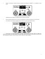
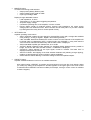
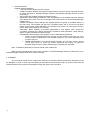
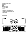
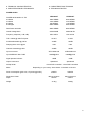
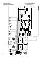
USER MANUAL
MANUAL DE INSTRUCCIONES
NOTICE D'EMPLOI
BEDIENUNGSANLEITUNG
USER MANUAL
1. IMPORTANT NOTE
1.1. Precautions
04
04
2. INTRODUCTION
04
3. INSTALLATION
05
3.1. Location, assembly, ventilation
3.2. Mains connection
3.3. Signal input connections
3.4. Output connections
3.5. Ethernet port
3.6. RS-232 port
3.7. FAULT connector
4. OPERATION AND USAGE
4.1. Start up
4.2. Front panel LED indicators
4.3. Front panel handling
05
05
06
06
06
06
06
07
07
07
08
5. CLEANING
12
6. FUNCTION LIST
13
7. FUNCTION DIAGRAM
13
8. TECHNICAL CHARACTERISTICS
47
9. BLOCK DIAGRAM
50
All numbers subject to variation due to production tolerances. ECLER S.A. reserves the right to make changes or
improvements in manufacturing or design which may affect specifications.
3
1. IMPORTANT NOTE
Congratulations! You are the owner of a carefully designed and manufactured equipment. We thank you
for trusting on us and choosing our amplifier NPA SPM (Networked All purpose Switching Power Mosfet).
In order to obtain maximum operativity and perfect functioning order, it is most important to carefully read
all considerations taken into account in this manual before connecting this amplifier.
We recommend our authorised Technical Services if any maintenance task should be needed so that
optimum operation shall be achieved.
1.1. Precautions
The amplifier should have an earth connection in good conditions (earth resistance, Rg=30Ω or less).
The environment must be dry and dustless. Do not expose the unit to rain or water splashes, and do not
place liquid containers or incandescent objects like candles on top of the unit. Do not obstruct the
ventilation grilles with any kind of material.
In case there is some type of intervention and/or connection-disconnection of the amplifier, it is most
important to previously disconnect the mains power supply.
Do not manipulate the output terminals to the loudspeakers when the amplifier is switched on, there are
voltages up to 400Vpp. The output cabling should be connected by a qualified technician. Otherwise only use premade flexible cables. There are no user serviceable parts inside the amplifier.
2. INTRODUCTION
With the PAM amplification series, ECLER introduced in early 90's a new concept to the world of
professional audio: The use of switching field effect transistors. The integration of these parts for audio applications
represents a firm and spectacular enhancement comparing to conventional amplifiers. These advantages can be
outlined as follows:
a) Lower internal resistance than bipolar transistors, which leads to less heating of the amplifier and more
powerful and controlled bass; conventional Mosfets have a 4 to 7 times higher internal resistance than switching
Mosfets.
b) The extremely high speed of these devices gives a transparency to the upper frequencies till now only
achieved by tube amplifiers. This fact also reduces TIM (transitory intermodulation) to very low levels.
The SPM-Technology (Switching Power Mosfet) has been developed and patented by ECLER Laboratorio
de Electro-Acústica, S.A. NPA line of amplifiers is a new step forward in the development of SPM amplification
technology, following in the successful DPA series footsteps.
SOA Contour following protection: the SOA is the safe operating area of transistors. A good protection
system should respect this area and its shiftings, as the SOA changes as a function of the operating temperature.
So, at 80°C it is considerably narrower than at 25°C, the start-up temperature. Some manufacturers decide to use
protection systems which compromise on the performance of the components. You get a fair protection, but the
performance remains mediocre. Others prefer to leave "dark" areas between the safe operating area and the
activation of protection, which is very risky indeed.
The new SOA contour following protection systems built into the NPA amplifiers guarantees total protection
of the amplifier at any output power, load or operating temperature, as the intelligent electronic circuitry
permanently watches for changes in the safety area, adapting itself to any situation.
Maximum damping factor: In NPA series traditional output relays have been replaced with a CROWBAR
electronic system. This device short-circuits the signal if surges that can damage the loudspeakers connected to
the amplifier are detected. On the contrary, any type of relay used in the conventional method introduces a
mechanical contact in the audio signal path to the speaker, contact that is exposed to wear and a significant
decrease in the amplifier damping factor.
4
Ecler NPA2500T/4000T makes use of a twin power supply and N-channel mosfets. This technology, which
has been successfully implemented in the industrial product line ENVIRO, allows for very high output power
without the use of bridge configurations. The NPA2500T/4000T keeps its "All the Power All the Time" philosophy,
even when driving 4 ohm speakers with a musical programme at maximum level.
NPA series incorporates in addition important technological innovations concerning digital processing and
remote management via Ethernet, turning it into the perfect candidate to address mobile applications and fixed
installations, both centralized and distributed, requiring high level remote control and monitoring and
integration with standard Ethernet networks. NPA amplifiers include as standard an EclerNet internal module
for DSP processing and remote management, allowing physical connection between the amplifier and an Ethernet
network and its management and remote supervision from any point of it, using Windows EclerNet Manager*
software. Please refer to the EclerNet Manager software manual for more information.
* EclerNet Manager software is available on www.ecler.com.
3. INSTALLATION
3.1. Location, assembly, ventilation
The NPA2500T/4000T amplifiers are 3 RU high 19'' rack modules.
It is important that the amplifier, as a heat source, is not placed next to other equipment nor exposed to high
temperatures. Therefore, the ventilation path should be kept free to allow fresh air entering the forced ventilation
tunnel. This system pulls air from the front, directly guiding it to the power modules and transformers, diverting a
part towards capacitors and forcing its output through the rear panel of the amplifier.
In order to optimize as much as possible the correct thermal dissipation of equipment installed in a closed
rack, it is advisable not to place power amplifiers under other appliances, but upon these ones.
All NPA amplifiers are supplied with plastic washers in order not to damage the rack ears when tightening
the screws.
3.2. Mains connection
The NPA amplifiers are fed with alternate currents, depending on the country, of 110-120, 220-240V
47/63Hz. (see characteristics in the back of the unit).
WARNING!: By convention, the mains wire colour assignment is the following:
- BROWN
- BLUE
- YELLOW/GREEN
=
=
=
Phase
Neutral
Earth
The mains cables must not be near the shielded cables carrying the audio signal, as this could cause
humming.
5
3.3. Signal input connections
NPA Series rear panel has analog and digital inputs. Input selection is performed from the front panel
menu or from EclerNet Manager control software. Please refer to the EclerNet Manager software manual for more
information.
•
Analog inputs:
The signal input connectors are of XLR-3 type (19), electronically balanced. The pin assignment is as
follows:
HOT or direct signal
COLD or inverted signal
GROUND
>
>
>
Pin 2
Pin 3
Pin 1
For unbalanced connection short-circuit pin 3 to pin 1.
The "STK OUTPUT" (18) are in parallel with the inputs and are used to supply the same input signal to
other amplifiers or sound systems.
The input impedance is 22KΩ (balanced) with a nominal input sensitivity of 0dBV(1V). This impedance
makes possible to parallel several amplifiers without loosing audio quality.
•
Digital inputs:
There is an XLR-3 connector for AES/EBU digital input as well as a matching digital output to re-send this
signal towards other devices.
3.4. Output connections
The "OUTPUT" section on the back panel is provided with Speakon® connectors (23).
STEREO/PARALLEL/BRIDGE operating modes are selected from the from panel menu or from EclerNet
Manager control software. Please refer to the EclerNet Manager software manual for more information.
The connection cable that joins the amplifiers outputs and the loudspeakers must be of good quality,
sufficient section and as short as possible. This is most important when the distances to cover are long ones i.e. up
to 10 meters it is recommended to use a section not inferior to 2.5mm2 and for superior distances 4mm2.
3.5. Ethernet port
An RJ45 connector allows connecting the equipment to an Ethernet network and its management from
EclerNet Manager software. Please refer to the EclerNet Manager software manual for more information.
3.6. RS-232 port
A DB9 connector for RS-232 allows a serial connection between the equipment and an external control
system, like AMX, Crestron, Medialon, etc. (non functional at the date of printing of this manual, will be available in
a future implementation).
3.7. FAULT connector
3 pins connector, potential-free closing contact (Normally Closed, Normally opened). Its status changes
when an internal amplifier failure is detected, placing this one out of service.
6
4. OPERATION AND USAGE
4.1. Start up
If the POWER (17) switch is operated on the rear panel, the amplifier receives mains power and can be
turned on locally or remotely (see Control panel section).
In a complete audio installation, it is important to start up the equipment in the following sequence: sound
sources, mixer, equalizers, active filters and finally power amplifiers. To turn them off the sequence should follow
an inverse pattern.
4.2. Front panel LED indicators
NPA amplifiers have a simple and effective indicators system:
•
THERMAL protection indicator (2):
It indicates that the cooling tunnel temperature has exceeded the minimal risk threshold for the equipment.
The amplifier automatically restarts once the temperature drops enough.
NPA amplifiers have a thermal protection per channel. This means each protection operates independently. It
can be activated for one channel only while the other is running smoothly.
•
PROTECT indicator (3):
It indicates the absence of signal at the speaker output. It can light up for the following reasons:
o At start-up and during the STANDBY time necessary to settle the amplifier internal voltages.
o Because of equipment fault preventing the normal booting (the LCD shows “PERSISTENT
PROTECT”).
o When the amplifier is delivering a very low frequency signal that could damage the speakers.
o When more than 4 short-circuits have been detected at the amplifier output over a period of 40
seconds (the LCD shows “REPETITIVE PROTECT”).
o When an internal fault occurred and the amplifier needs to be fixed (the LCD shows “FAULTY
AMPLIFIER”).
In any case, permanent lighting of these indicators is a symptom of faulty operation and the cause that led
to this activation should be investigated.
•
CLIP indicator (4):
It lights up when the signal delivered to the speakers is near clipping. The CLIP system considers possible
voltage fluctuations of power supply, always giving a real indication even if they exist. It is normal for CLIP
indicators to be lit at the bass frequencies rhythm for high operating levels, as these frequencies have the higher
energy content. You must take care that these indicators do not permanently light up during normal operation of
the equipment.
•
SIGNAL presence indicator (5):
It indicates a signal presence at the amplifier inputs. These indicators light up when the input signal
exceeds -40 dB.
•
DATA transfer indicator (11):
It blinks to indicate data transfer activity between the amplifier and a remote control PC running EclerNet
Manager.
7
4.3. Front panel handling
The front panel includes a series of controls and indicators:
o
o
o
o
o
Backlit LCD display for displaying menus, settings and amplifier parameters.
On / Off key (POWER ON).
Menu navigation keys (MENU / PREVIOUS / NEXT).
Rotary/push controls for adjusting parameters (CHANNEL 1 / CHANNEL 2).
LED indicators (see section 4.2).
To power up the unit, press and hold the POWER key until the boot sequence starts. The shutdown will
also require pressing and shortly holding the same key.
POWER ON key has an integrated LED indicator lighting up in orange when the amplifier is in STAND BY
mode, in green when ON, and in red during the boot sequence or when the amplifier is in protect mode.
Once the power amplifier in on, the main screen appears in the LCD display, looking like the following:
From this main screen you can perform a number of basic functions on the amplifier:
•
Change the volume of channel 1 or 2 (turning rotary controls CHANNEL 1 or CHANNEL 2):
A window briefly appears to show the setting in dB (-47 dB in the given example) and the volume ramp
indicator changes for this channel.
Note: when both channels are linked, the CHANNEL 1 rotary knob adjusts simultaneously both channels
volume.
8
•
Activate / deactivate a channel muting (by pressing and holding the CHANNEL 1 or CHANNEL 2 rotary
knob):
A label with the text "MUTE" is displayed when this feature is activated.
•
Show text labels assigned to the unit and to its amplification channels (by clicking on the TAG button):
This window, named TAGS, disappears after a short time, and the main window returns.
The top line of the screen also displays the active PRESET number and name. When you modify any
setting of the amplifier a "M" label appears in the upper right corner of the screen to indicate that the PRESET has
been modified (for example, moving a volume control is sufficient to make it happen).
9
All other amplifier functions and settings are accessed through the menu structure as described in the
following diagram:
10
•
MONITOR menu
VU-meters monitoring scale selection:
o Output power (Watts), RMS or peak.
o Output voltage (Volts), peak or RMS.
o Input signal voltage, RMS.
Display through dedicated screens:
o Load impedance, in ohms.
o Temperature, in % of the alarm triggering temperature.
o AC power supply voltage.
o Cumulative operating time of the amplifier, in hours: minutes.
o Events: digital counter of protection alarms, thermal, load impedance, AC power supply
voltage (note: from within this menu, alarm counters can be reset (value = 0) for each channel
by holding down the rotary knob for a short period of time).
•
SETTINGS menu
Amplifier operating mode menus:
o INPUT SOURCE: selects the input signal for the amplifier to work with, amongst the available
ones (Analog 1, Analog 2, Digital 1, Digital 2 and internal generator).
o LINK VOLUME: determines whether the volume controls on both channels of the amplifier will
be linked (ON) or independent (OFF). In linked mode, the CHANNEL 1 rotary knob sets the
volume for both channels simultaneously and the label "LINK" is displayed.
o GAIN: selectable amplifier gain between 26, 32 or 38 dB.
o OUTPUT MODE: operating mode selection for amplified outputs between stereo, parallel or
bridge. For the two last ones, the label "PARAL" or "BRIDGE" is displayed.
o POLARITY: phase selection for the input signal, normal or inverted. The label "INV" is
displayed if the phase is inverted.
o ANTICLIP LEVEL: anti-clipping circuit level selection between soft (allowing a large clipping),
medium or hard (allowing a minimum clipping, almost negligible).
o PEAK LIMITER: allows defining a maximum voltage for the unit amplified outputs.
•
PRESETS menu
Amplifier PRESETS selection in a list of 10 available memories.
Note: when loading a PRESET, its number and name appear on the top line of the display. When
you modify any setting of the amplifier an "M" label appears in the upper right corner of the screen
to indicate that the PRESET has been modified (for example, moving a volume control is sufficient
to make it happen).
11
•
ADVANCED menu
Amplifier advanced features:
o LCD CONTRAST: adjusts the LCD contrast.
o FINDER: enables / disables the display backlight flashing, useful to identify a physical unit with
its virtual equivalent in EclerNet Manager software (see EclerNet Manager manual for more
information).
o INFO: shows the amplifier model and firmware version.
o NETWORK: allows setting IP address, mask and gateway for the amplifier Ethernet interface
(The default port is 2210. You can not change it with local controls, but with EclerNet Manager
software only).
o POWER ON MODE: allows selecting the amplifier behavior at power-up (POWER switch on
the rear panel). The amplifier can start up in STANDBY mode, ON or recover its last status
before the last power supply interruption, for example in the event of a mains power recovery
after a mains power failure (LAST STATE).
o RESTORE: allows resetting all amplifier parameters to their default value, except the
cumulative operating time (erases passwords, PRESETS, DSP parameters, setup settings,
alarms counters and Ethernet network setup).
o PASSWORD: allows assigning the amplifier a user or administrator password.
• USER: once this password has been set, the unit will request it each time you try to
use any control or adjustment in the amplifier setup (on, off, volume adjustment and
access to menus).
• ADMIN (administrator): once this password has been set, only main screen controls
can be used: power on, power off, volume adjustment and muting. To adjust the
amplifier setup (access to menus, MENU key) the password is requested.
Note: To disable a password you need to rewrite it with a blank one.
Most functions described above have their equivalent in EclerNet Manager software. Please refer to the
EclerNet Manager software manual for more information.
5. CLEANING
The front panel should not be cleaned with dissolvent or abrasive substances because silk-printing could
be damaged. To clean it, use a soft cloth slightly wet with water and neutral liquid soap; dry it with a clean cloth. Be
careful that water never gets into the amplifier through the holes of the front panel.
12
6. FUNCTION LIST
1. Input attenuator
2. Thermal protection indicator, THERMAL
3. Protection indicator, PROTECT
4. Clip indicator, CLIP
5. Signal present indicator, SIGNAL
6. Display
7. Navigation key, MENU / CANCEL
8. Navigation key, PREVIOUS
9. Navigation key, NEXT / TAG
10. On / Off key, POWER ON
11. Data transfer indicator, DATA
12. RS-232 port
13. Ethernet port
14. Binding post block, FAULT
15. Digital input XLR connector, AES-EBU INPUT
16. Digital output XLR connector, AES-EBU OUTPUT
17. Start-up switch
18. Output XLR connector to other amplifiers, STK OUTPUT
19. Input XLR connector, INPUT
20. Earth terminal, GND
21. Mains cable
22. Switch to disconnect chassis earth / electrical Ground, GND LINK
23. Speakon® connectors to the loudspeakers
7. FUNCTION DIAGRAM
13
8. TECHNICAL CHARACTERISTICS
8. CARACTERISTIQUES TECHNIQUES
8. CARACTERÍSTICAS TÉCNICAS
8. TECHNISCHE DATEN
POWER AUDIO
NPA2500T
NPA4000T
POWER 20Hz-20kHz 1% THD
2Ω Stereo
4Ω Stereo
8Ω Stereo
8Ω Bridged
1650 WRMS
1150 WRMS
695 WRMS
2290 WRMS
2840 WRMS
1910 WRMS
1120 WRMS
3800 WRMS
Peak Power 2Ω/1kHz
3850 WRMS
6200 WRMS
Overall Voltage Gain
26/32/38 dB
26/32/38 dB
Frequency response (-1dB, -3dB)
6Hz-37kHz
6Hz-37kHz
THD + Noise @ 1kHz Full power
<0.04%
<0.04%
S+N/N 20Hz-20kHz @ 1W/4Ω
>84dB
>84dB
Damping factor 1kHz @ 8Ω
>350
>350
Channel Crosstalk @ 1kHz
>80dB
>80dB
XLR3 balanced
XLR3 balanced
>60dB@1kHz
>60dB@1kHz
-40dB
-40dB
Speakon®
Speakon®
Input connectors
Input CMRR/ref. Max. PWR
Signal present indicator
Output connectors
Anticlip limiter
Mains
3 level DSP controlled 3 level DSP controlled
Depending on your country. See charact. in the back of the unit.
Power consumption (pink noise, 1/8 power @ 4ohm)
Power consumption (pink noise, 1/3 power @ 4ohm)
Dimensions Panel
Depth
Weight
1500VA
2400VA
2500VA
3800VA
482.6x132.5mm
532mm
482.6x132.5mm
532mm
31.2kg
35.8kg
47
DIGITAL
Processing:
A/D & D/A
DSP
Latency
24 bit, 96kHz. S/N:110dB/115dB AKM
32/64 bits
824μs
Analog Input headroom:
Digital Input attenuator:
Input Impedance:
Maximum Delay:
Delay resolution:
+18 dBV = +21dBu
Stepless from –∞ to +0dB
Balanced, 22kΩ
1s (343.4m) total for all 2 channels.
10.4µs (3mm)
Compressor / Limiter:
Threshold
Ratio
Attack time
Release time
from -36dBV to +18dBV
1:1 to ∞:1 (limiter)
Auto or from 0.1ms to 500ms.
Auto or from 1ms to 5s.
High & Low pass Crossover filters
Butterworth in 6/12/18/24dB/oct.
Bessel in 12/18/24dB/oct
Linkwitz-Riley in 12/24dB/oct.
Parametric Eq types (8 max. per output)
- Bypass / On-Off all channels
- Param. Eq. 20Hz-20kHz; -60/+12dB; Q from =.3 to 200
- Low & High Shelf 6/12 dB/oct
- Low & High Pass 6/12 dB/oct.
- All-Pass 1/2 order
Built In signal generator
- Sine (20Hz to 20kHz)
- Polarity(20Hz to 20kHz)
- White
- Pink
Signal Mute
Signal Polarity Invert
Yes
Yes
Connectivity:
- Ethernet Base-Tx 10/100Mb Auto X-Over Cat5
- Rs-232
- Fault relay N.O./N.C.
- AES / EBU (In / Out) 8kHz to 96kHz (may be optional
on some units).
48
SOFTWARE
eclernet Software
- Realtime full GUI of all functions and controls thru Ethernet
with interactive graphical display
- Grouping mode channels or devices
- Automated report generation
- Remote power on with programmable delay.
- Up to 256 devices on same net.
- Autodiscovery devices feature
- Routing capability through NAT gateways.
- Real time metering at input / output
- Mains metering
- Output Load supervision
- Output peak voltage compressor
- Finder feature
- Save & Recall setup and preset functions
- Firmware update capability thru Ethernet
- Two level Password protection
- Default Network configuration:
IP: 192.168.0.100
Mask: 255.255.255.0
Gate: 192.168.0.1
UDP Port: 2210
Operating System:
Windows® W2000 Prof. (SP4); XP Prof. (SP3); Vista (SP1).
Minimum eclernet System Requirements:
Pentium IV ® 1GHz
256MB RAM
40MB HDD free space
800x600 pixels & 16bits color display
10/100 Ethernet Network card
49
9. BLOCK DIAGRAM
9. BLOCS DE DIAGRAMMES
50
9. DIAGRAMA DE BLOQUES
9. BLOCKSCHATBILD
51
ECLER Laboratorio de electro-acústica S.A.
Motors 166-168, 08038 Barcelona, Spain
INTERNET http://www.ecler.com E-mail: [email protected]
50.0168.01.00