1
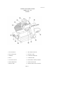
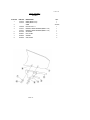
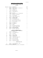
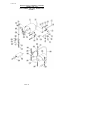
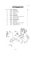
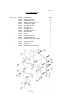
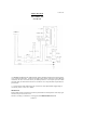
INSTRUCTION
MANUAL
7510,7512
DURO SERIES Slicer
WE THANK YOU FOR YOUR PURCHASE OF OUR
MODEL 7510, 7512 SLICER.
SINCE 1948
7510/12/1099
ED7
7510/7512
TABLE OF CONTENTS
DESCRIPTION
PAGE
Table of Contents
List of Illustrations
Introduction
Installation Instructions
Important Safety Warnings
Operating Instructions
Sharpening Instructions
Operator's Care of Slicer / Lubrication
Trouble Shooting Chart
Mechanics Maintenance
Repair, incl. Disassembly, Replacement and Reassembly
Replacement of Parts, List
Warranty
1
1
3
3
3
4
4-5
5-6
8
9
10-12
13-26
Back Cover
LIST OF ILLUSTRATIONS
ILLUSTRATION
PAGE
Figure 1
Figure 2
Figure 3
Figure 4
Figure 5
Figure 5A
Figure 6
Figure 7
Figure 8
Figure 9
Figure 9A
Figure 10
Figure 10A
Figure 11
Figure 11 A
Figure 11B
2
7
13-14
15
16
17
18
19
20
21-22
23
24-25
26
27
28
29
Overall View of Meat Slicer, Model 7510-7512
Lubrication Diagram, Model 7510-7512
Base and Knife Housing Assembly
Sharpening Assembly
Carnage Assembly, Model 7510
Carnage assembly, Model 7512
Carnage Ann and Slide Assembly
Slice Adjustment Assembly
Fence Assembly
Motor, Mount and Drive Assembly 115V, 50/60
Capacitor Panel 100V, 50/60HZ, 1PH
Motor, Mount and Drive Assembly 220V, 50HZ
Capacitor Panel 220-240 V, 50/60HZ, 1PH
Electrical Wiring Diagram (115V , 60/50HZ , 1PH)
Electrical Wiring Diagram (220-240V, 50/60HZ, 1PH)
Electrical Wiring Diagram (100V, 50/60HZ, 1PH)
PAGE 1
7510/7512
OVERALL VIEW OF MEAT SLICER
MODEL 7510 - 7512
FIGURE 1
1 ON-OFF SWITCH
8
ADJUSTMENT SPACER
2 INDICATOR LIGHT
9
ELECTRIC CORD
3 CARRIAGE
10 CARRIAGE ARM KNOB
4 FENCE
11 CARRIAGE ARM
5 LAST SLICE DEVICE
12 REMOVABLE CHEESE SCRAPER
6 KNIFE SHARPENER
13 GRADUATED KNOB
7 KNIFE GUARD
14 SERIAL NAME PLATE (ON REAR)
PAGE 2
7510/7512
INSTRUCTION MANUAL
INTRODUCTION
This manual contains instructions for the Installation, Operation, Care, Maintenance and Repair of the
Meat Slicing Machine. Disassembly, Replacement and Reassembly Instructions are included. A
trouble shooting guide is provided. A complete Replacement Parts list with identifying figures is also
included to facilitate identification and ordering of replacement parts.
INSTALLATION INSTRUCTIONS:
INSPECTION
All Univex slicers are inspected and tested at the factory; however, they should be reinspected
carefully by the person making the installation for loose, damaged or broken parts. Detached parts and
fixtures should be checked against packing list to determine all are present. Any damages should be
reported to t he Carrier immediately, and any shortages of parts or fixtures reported to Univex
Corporation.
WARNING: After slicer has been inspected, wash slicer completely with warm water and mild soap.
For SAFETY follow the cleaning instructions on page 5-6.
INSTALLATION:
The most efficient installation of your Univex slicer will depend upon the layout of your kitchen.
Locate your slicer where it will save steps for the operator and be sure to provide sufficient clearance
around it for ease of maintenance and cleaning, as well as for efficient and safe use.
Slicer should be operated on a sturdy bench or table with the height determined to suit the operator. It
is most important that the forearm of the operator be at the proper level for ease and safety of
operation as well as for maximum production. This height is considered optimum when the carriage
handle (Figure 1 [11]) of the slicer is at approximately the height of the operator's elbow when
standing.
IMPORTANT
WARNING\CAUTION: Electrical wiring instructions are found in the wiring diagram fFig. 11. Fig.
11 A and Fig. 11B). Before making electrical connections, CHECK the
specifications on the name plate to make sure that they agree with those on
your electrical service. A grounding type three terminal plug is provided for
safety. If you do not have a mating receptacle, have a qualified electrician
provide grounding provisions in accordance with local safety codes.
IMPORTANT SAFETY WARNINGS
The slicer knife is extremely sharp! Never touch the knife, always keep hands and fingers clear of the
knife. Never run slicer without the guard or other parts in place and securely fastened. Take extra care
to avoid accidents by keeping the knife guard and sharpening assembly cover ON at all times. When
the machine is not in use, the slice adjustment knob should be turned back to the closed position
(beyond "0") so that the knife edge is not exposed.
Observe the cleaning instructions on Page 5-6 for best results and for safety. Also remember to always
turn off slicer and disconnect the electrical supply cord.
When slicing, always work the carriage using only the carriage arm handle (Figure 1 [11]). Do not
hold or push the carriage from any other place.
PAGE 3
7510/7512
OPERATION INSTRUCTIONS
The Univex slicer is designed to meet the Cook's demand for an efficient, sturdy slicer. The Univex
slicer will give unfailing performance over a period of years, when operated and maintained
according to instructions contained herein.
START/STOP SWITCH
The slicer is started by pushing the start/stop toggle switch (Figure 1 [ 1 ]) upward to the ON position.
A pilot light (Figure 1 [2]) is provided to indicate when the slicer is turned on.
SLICE ADJUSTMENT
WARNING: Dial type knob adjustment (Figure 1 [13]) allows for slice thicknesses ranging from
paper thin up to 5/8". Dial graduations allow you to precisely set up specific slice
thickness for various needs. When not in use, always return knob back to its fully
closed position (beyond "0") so that the knife edge is not exposed.
POSITIVE HOLD CARRIAGE
CAUTION: A last slice gravity feed grip (Figure 1 [5]) is provided which can be locked out of the
way when not required. Do not use this last slice device to work the carriage back and
forth. Use only the carriage arm handle (Figure 1 [11]).
Always make sure the carriage is positively secured to the slicer by checking to see that the carriage
arm knob (Figure 1 [10]) is fully tightened. Failure to do this could result in t he carriage striking and
damaging the knife edge.
KNIFE GUARD
WARNING: The knife guard (Figure 1 [7]) covers the knife edge completely except under the
sharpener cover and the forward edge where slicing will be performed. This forward
edge is covered by the edge of the fence, but only when the slice adjustment is
completely closed.
The knife guard (Figure 1 [7]) can be removed for cleaning by unscrewing the knife
guard knob (Figure 3 [2]). For safety, keep the knife guard on at all times except when
cleaning. Never operate the slicer with the knife guard removed.
SHARPENING INSTRUCTIONS
This slicer is equipped with a knife having a concave or hollowed rear surface for superior slicing
quality. Of course, any knife however superior must be sharpened regularly and properly in order to
produce not only the highest quality slices, but also to allow it to maintain its productivity. The knife
sharpener (Figure 1 [6]) on this machine is a top mounted built -in design for simplicity and ease of
use. It even has an automatic aligning feature.
WARNING: The following sharpening procedure will provide high quality sharpening results and
should also be followed for safety considerations:
(1) WARNING: Keep away from the knife edge.
(2) Completely close the slice adjustment (beyond "0") so that the knife edge is not exposed.
(3) The knife's cutting area should be clean and free from food, especially grease. Grease will ruin the
ability of a grinding stone to sharpen an edge. The stone simply will not cut. If cleanin g is
PAGE 4
7510/7512
necessary, follow the procedure outlined on Page 5-6. Remember to unplug the electrical supply cord.
(4)
Loosen sharpener lock pin (Figure 3 [4]) which bears against sharpener post, then lift sharpener assembly
(Figure 1 [6]) and rotate it 1/2 turn (180 degrees). Then seat it down over knife.
(5)
Tighten sharpener lock pin (Figure 3 [4]). As the lock is tightened, it bears on the sharpener post and
automatically aligns the grinding and debumng stones to the precise orientations which are preset at our
factory.
(6)
Turn slicer ON. Depress the sharpener button and hold in which will start the grinding wheel rotating. Run
until the beveled cutting surface cleans up. This can take from30 seconds to several minutes depending on
how dull the blade was allowed to become. Release sharpener button.
(7)
Turn slicer OFF and check for the formation of a very slight burr on the side of knife opposite the bevel
which indicates complete grinding of the bevel. This slight burr can be detected either visually of by picking
with a small piece of stiff paper.
(8)
Turn slicer ON. Lightly press deburring (honing) button and hold for 1 to 2 seconds while you turn OFF the
slicer. Blade should now be completely sharpened and honed.
CAUTION: It is very important for best slicing results not to deburr the knife too lone or the keen edge will
be destroyed due to the formation of an undesirable second bevel on the opposite side. This condition tends to
be the primary cause of unsatisfactory slicing results.
(9)
Turn slicer OFF. Loosen lock pin, ( Figure 3 [4]) then lift and return sharpener to its storage position. Tighten
lock pin.
(10)
Clean slicer and knife according to the cleaning procedure on Page 5-6 in order to thoroughly remove
grinding debris.
OPERATOR'S CARE OF SLICER
CLEANING
WARNING: 1.
Never touch the knife. Always keep your hands, fingers and arms clear of knife.
2.
Turn off slicer and DISCONNECT ELECTRICAL CORD (Figure 1 [9]) before cleaning.
Leave protective guard in place.
3.
Turn slice adjustment knob (Figure 1 [13]) to the fully closed position (beyond "0") so that the
knife edge is not exposed.
WARNING: 4.
Remove carriage assembly (Figure 1 [11]) which may be washed in a sink. Use care in
washing the sharply pointed prongs on the last slice feed grip. (Figure 1 [5]) Wash this area
thoroughly. A small b ristle brush is recommended. Use only warm water and mild soap. Rinse
carriage assembly with warm water and dry thoroughly using a clean soft cloth.
Never use detergents nor wash the slicer or any of its parts in a dishwashing machine or the
clear protective finish will be damaged.
PAGE 5
7510/7512
WARNING: 5.
6.
Wash body of slicer using warm water and mild soap using a soft cloth. Under
no circumstances should the slicer be hose rinsed. It is recommended that the
cloth be folded over a thin wooden stick when cleaning between the fence plate
and the knife.
Remove knife guard (Figure 1 [7]) by loosening knife guard knob (Figure 3 [2])
and pushing the long stud upward to lift the knife guard above surface of knife.
Then carefully lift and remove guard.
7.
Remove Knife deflector (Fig. 3 [19]) by unscrewing Knife deflector screw (Fig.
3 [21]).
WARNING: 8.
CAREFULLY wash the front and rear of the knife with a cloth using warm
water and mild soap. It is recommended that the cloth be folded over a thin
wooden stick as a further caution to avoid accidental contact with the knife.
Rinse with warm water applied with a cloth. Dry thoroughly with a clean soft
cloth.
Following cleaning, a commercial non-toxic sanitizer may be wiped on the
clean surfaces with a soft clean cloth or sprayed as recommended on the
container labeling. It is important that the sanitizer be compat ible with anodized
aluminum or the clear protective finish on the slicer will be damaged. Surfaces
should be wetted completely, but not to the point of running or puddling.
WARNING: 9.
WARNING: 10. Replace the knife guard. Never leave the slicer without its knife guard installed.
11. Replace Knife deflector.
LUBRICATION
Lubrication instructions are given in Figure 2 on Page 7. Operator's attention is called to lubricating
the slide bar (Figure 6 [4]) as needed for smooth carriage motion, but at least monthly with three
drops of mineral oil.
Shafts to the last slice grip and to the auxiliary fence (Figure 5 [7,10]) (Figure 5A [8,12] should be
lubricated as necessary with petrogel. Distribute over surfaces by moving the grip and fence back and
forth. Wipe excess petrogel, from shafts with a clean cloth.
PAGE 6
7510/7512
LUBRICATION INSTRUCTIONS
MODEL 7510 - 7512 FIGURE 2
A PETROGEL, AS REQUIRED TO MAINTAIN
LIGHT FILM,
PAGE 7
B OIL MONTHLY, THREE DROPS
MINERAL OIL.
7510/7512
TROUBLESHOOTING GUIDE
7510/7512
TROUBLE
1. Slicer will not
operate.
POSSIBLE CAUSE
1.1 Electrical service down.
1.2 Burned switch contacts.
1.3 Motor capacitor defective.
1.4 burned out motor
REMEDY
1.1 Check electrical service.
Replace fuse or reset circuit
breaker as necessary.
1.2 clean or replace.
1.3 replace.
1.4 Remove, test, repair or replace
2. Motor running, blade 2.1 Belt tension too tight
2.1 Readjust belt tension.
not turning.
NOTE: Often after a long period of no use, such as in storage, the belt
flows and takes a set in the pulley ribs. A slight urging of the
knife with a wooden stick will get the slicer turning with no
further problems.
DO NOT USE HANDS TO TURN KNIFE.
3. Slippage of knife
during slicing.
3.1 Loose or broken belt.
3.2 Grease or oil on belt.
3.1 Adjust belt tension or replace
belt.
3.2 Clean pulleys with safety
approved cleaning solvent
on soft clean rag. Replace
belt.
4. Motor stalls during
slicing.
4.1 Knife cutting edge to dull or
improperly sharpened.
4.1 Sharpen using the procedure
specified. Use care not to use
homing stone longer then the 1
4.2 Product such as cheese old and
or 2 seconds.
dried out.
4.3 Low voltage service.
4.2 Reduce thickness of slice.
4.4 Belt tension
excessive.
4.3 Have electrician check
service voltage.
4.4 Readjust belt tension.
5. Excessive noise.
5.1 Knife contacting the
knife guard.
5.1 Tighten knob which secures
guard.
5.2 Badly worn or frayed
belt.
5.2 Replace belt.
5.3 Motor pulley and belt
misaligned.
5.4 Tighten set screw.
5.3 Realign motor pulley.
5.5 Clean knife and plastic scraper
5.4 Loose set screw in motor pulley
5.5 Dirty knife rubbing against
plastic scraper
6. Smearing or tearing 6.1 Soft cheese is at room
6.1 Chill soft cheese for best slicing
when slicing soft
temperatur e.
results.
cheese.
6.2 Knife dirty with hard dried on 6.2 Clean knife thoroughly.
product.
PAGE 8
7510/7512
MECHANIC'S MAINTENANCE
Every year a mechanic or service technician should perform the following inspection and carry out the respective
maintenance as required:
FOR SAFETY, TURN OFF SLICER AND DISCONNECT ELECTRICAL CORD.
1. BELT DRIVE: This d rive features a multi-ribbed high performance belt for long trouble-free service. Inspect
belt for proper tension. If glazed or excessively worn, replace. A tensioning device automatically allows for
normal belt wear-in and stretching. However, if additional tension is required, it may be obtained by turning
adjustment nuts (Figure 9/10 [18]) clockwise on take up rod (Figure 9/10 [24]) which will further compress
the tensioning spring. As a guideline, the compressed length of the spring should be approximately 7/8".
2. MOTOR: Motor is pre-lubricated and requires no periodic maintenance or relubrication in normal kitchen
usage. Provision for re-lubrication in extreme duty applications is provided by means of oiling orifices at
both shaft end and opposite ends of motor. A light weight electric motor oil or #10 non-detergent oil may be
used.
3. SLICE ADJUSTMENT: Check, by turning the slice adjustment knob (Figure 3 (271) to make sure that the
fence is closing completely (below "0" on knob) and that k nife edge is not exposed. If fence is not closing all
the way such that the edge of the knife is exposed, proceed to loosening the lock nut (Figure 7 [29]) and turn
the slice adjustment stop screw (Figure 7 [28]) so the knob can be turned further enough to allow the knife
edge to not be exposed. Now re-tighten the lock nut (Figure 7 [29]). Loosen the two set screws in the slice
adjustment knob (Figure 3 [26]) and re-adjust its zero position, then tighten the two set screws. Actually, the
closed or zero set position on the knob should be in the red colored zone of the knob's dial.
4. CARRIAGE: Check for free smooth operation of auxiliary fence, last slice device and for smooth travel of
carnage arm (Figure 6 [19]) Check for excess backlash between slice b earing (Figure 6 [ 14]) and carriage
slide (Figure 6 [7]). The correct lash (clearance) required for smooth carriage operation is obtained when a
very slight lash or movement can be detected. Too much lash can result in the carriage striking and damaging
the knife edge. Too little lash results in binding and a loss of smoothness in carriage travel. Lash is adjusted
by loosening locknut (Figure 6 [10]) and turning brass rubbing screw (Figure 6 [11]) clockwise to reduce lash
and counterclockwise to increase l ash. Tighten locknut while holding rubbing screw stationary with a
screwdriver so it does not move. Grease only the side of the carriage slide (Figure 6 [7]) on which this brass
rubbing screw slides.
5. LUBRICATION & FUNCTION CHECK: General lubrication should be performed in accordance with the
lubrication instructions in Figure 2. during this lubrication sequence, be sure to check for free operation and
movement of related parts as well as for excessive wear and looseness of various parts. Be sure to check all
handles and knobs for tightness.
6. KNIFE: Check knife edge to see that it has been properly sharpened. If there is any evidence of incorrect
sharpening procedure, such as excessive honing, alert owner and operator.
PAGE 9
7510/7512
REPAIR INSTRUCTIONS
(including disassembly, replacement and reassembly.)
Always turn off slicer and disconnect electrical cord before doing any maintenance or repair on the slicer. Keep
guards on all times. Keep slice adjustment fully closed so knife edge is not exposed. Keep sharpener assembly also
in place so top of knife edge is not exposed.
DRIVE BELT
1.
Disconnect electrical power cord.
2.
Remove four rubber suction feet (Figure 3 [37]) that secure bottom cover (Figure 3 [36]) to slicer.
3.
Remove nuts (Figure 9 [18]) from tensioning take-up rod (Figure 9 [24]) so motor can be pivoted to give belt
slack. Be careful not to lose tensioning spring (Figure 9 [19]).
4.
Note the position of the belt on the pulley to insure proper installation of new belt.
5.
Unwrap belt from motor pulley.
6.
Reinstall rubber feet (Figure 3 [37]) and place slicer upright (operating position).
7.
Loosen sharpener lock pin (Figure 3 [4]). Lift and remove sharpening unit. Set aside.
8.
Remove knife guard knob (Figure 3 [2]) and carefully remove knife guard (Figure 3 [14]).
9.
Using caution to avoid the sharp knife edge, remove the four screws (Figure 3 [12]) that secure the knife
Carefully remove knife and set aside with its flat side down, flush on a bench so the edge is not exposed.
10.
Note the position of the belt on the pulley to insure proper installation of new belt.
11.
Unwrap and remove drive belt from the knife pulley (Figure 3 [10]).
12.
Wrap replacement belt on knife pulley and motor pulley. Do n ot reinstall knife at this time.
13.
Reinstall spring and nuts on tensioning take up rod (Figure 9 [24]) and tighten. It is important to make sure
that the belt is aligned on both pulleys.
14.
Belt tension is correct when the spring is compressed to an o verall length of 7/8".
15.
Connect electrical power and operate slicer to check that belt and pulleys are running true.
16.
Disconnect electrical power cord.
17.
Reinstall bottom cover and secure with the four suction feet.
18.
Using caution, reinstall knife and secure with four screws.
19.
Reinstall knife guard and secure with knife guard knob.
20.
Reinstall sharpener and secure with lock pin.
PAGE 10
7510/7512
KNIFE (Removal Figure 3)
1.
Disconnect electrical power cord.
2.
Loosen sharpener lock pin (Figure 3 [4]), then lift and remove sharpening unit. Set aside.
3.
Remove knife guard knob (Figure 3 [2]) and carefully remove knife guard (Figure 3 [14]).
4.
Using caution to avoid the sharp knife edge, remove the four screws (Figure 3 [12]) that secure knife
(Figure 3 [15]).
5.
Carefully remove knife and set aside with its flat side down flush on a bench so the edge is not
exposed.
6.
Reinstall new knife in the reverse procedures outlined above.
7.
Even though a new knife is very sharp, the sharpening procedure specified on pages 4 and 5 should
be performed to true the new knife's bevel to the slicer.
WARNING: Worn knife should be disposed of in a safe, responsible way, showing concern for other
who may handle it. It is recommended that the edge of the knife be wrapped several time
with heavy tape and that a caution (CAUTION, SHARP EDGE) be written on both sides
of the knife.
KNIFE SEAL (Figure 31
1.
Remove knife per above instruction.
2.
Unscrew and remove knife insert stud (Figure 3 [16]). Maintain shims that may have been used in
assembly.
3.
Using a small screwdriver, carefully pry and remove the knife seal (Figure 3 [11]) from the knife
pulley (Figure 3 [10]).
4.
Apply light film of mineral oil on outer diameter and lip of rubber seal.
5.
Clean recess in pulley.
6.
Drive seal into recess in pulley using care to avoid damage to seal. Seal should be seated uniformly.
7.
Check knife insert stud (Figure 3 [16]) for small sharp burrs that may have been raised during its
removal. Remove burrs if present with a fine-toothed file. If burrs are not removed, they will destroy
the seal very quickly.
9.
Reinstall knife insert stud and shims that may have been present. Apply three drops of mineral oil to
the seal/stud interface.
11. Reinstall knife, guard and sharpener in the reverse procedure outlined above.
PAGE 11
7510/7512
SHARPENING STONES
1.
Disconnect electrical cord.
2.
Unscrew sharpener lock pin (Figure 3 [4]).
3.
Lift up sharpening assembly (Figure 1 [6]) and remove from slicer.
4.
Using an open end wrench, unscrew cover knob (Figure 4 [1]). It is recommended that a piece of tape or paper
be temporarily wrapped around knob prior to unscrewing it so as to protect its finish.
5.
Gently remove lever cover (Figure 4 [2]) off of mounting block (Figure 4 [26]). Perform this step slowly taking
care to remove cover evenly from the two locating pins (Figure 4 [9]) on which it fits snugly.
6.
Unscrew nut (Figure 4 [21]) and remove along with washer and sharpening stone (Figure 4 [23]).
7.
Install new sharpening stone. Flat face should be toward the outside.
8.
Re-attach washer and nut.
9.
Honing (deburring) stone (Figure 4 [14]) is removed by first unscrewing lock screw (Figure 4 [19]) from
thimble (Figure 4 [18]).
10. Gently remove thimble taking care to not lose the small ball bearing and spring (Figure 4 [16 & 17]) which are
inside.
11. Unscrew nut (Figure 4 [15]) and remove along with washer and honing stone (Figure 4 [14 & 20]).
12. Install new honing stone with the flat face toward the inside.
13, Re-attach washer, nut, and thimble.
14. Re-attach cover and reinstall in the reverse procedures (5. through 1,).
REPLACEMENT OF PARTS LISTS
Replacement parts for the Food Slicing Machine are shown in the following Figures. When ordering replacement
parts, always include the model and serial numbers of the ma chine in addition to the specific part number.
PAGE 12
7510/7512
BASE AND KNIFE HOUSING ASSEMBLY
MODEL 7510 - 7512
FIGURE 3
ILLUS. NO.
PART NO.
1.
2.
3.
4.
5.
7510012
7510015
7510013
7510150
7510001
7512001
7510156
7510002
7510158
7510004
7510154
6509012
6509014
8512240
7510011
7512011
7510009
7512009
7510008
7512008
1012167
6.
7.
8.
9.
10.
11.
12.
13.
14.
15.
16.
17.
18.
19.
20.
21.
22.
23.
24.
25.
26.
27.
28.
29.
30.
31.
32.
33.
34.
35.
36.
37.
38.
39.
40.
41.
42.
43.
44.
7510022
8512206
7510023
7510019
8512208
8512210
6509098
8512214
7510084
8512211
8512209
7120009
7120009
7120011
7120009
7120014
7120041
4400081
7120026
7120126
7510094
7510014
7510021
8512525
7510020
7120130
8512326
4400338
DESCRIPTION
WASHER, KNIFE
KNOB, KNIFE GUARD
NUT KNIFE
LOCK PIN, SHARPENER
BACK KNIFE GUARD (MODEL 7510)
BACK KNIFE GUARD (MODEL 7512)
WASHER, KNIFE SHIM
SHAFT, KNIFE
WASHER, KNIFE SHIM
SPACER
PULLEY, KNIFE
BUSHING, KNIFE
SCREW, BLADE
SCRAPER, BLADE
KNIFE GUARD (MODEL 7510)
KNIFE GUARD (MODEL 7512)
BLADE (MODEL 7510)
BLADE (MODEL 7512)
INSERT, KNIFE 7510
INSERT, KNIFE 7512
BALL BEARING
RESERVED
KNIFE DEFLECTOR
LOCATING PIN
KNIFE DEFLECTOR SCREW
SLICER BODY
GRADUATED KNOB BUSHING
FRONT WHEEL
SET SCREW
SET SCREW
GRADUATED KNOB
REAR WHEEL
RIVET
ON-OFF SWITCH
SWITCH JAM NUT (PART OF SWITCH)
SWITCH GUARD
SWITCH JAM NUT (PART OF SWITCH)
INDICATOR LIGHT 115V
INDICATOR LIGHT 220V
SCREW, DOME DRIVE, NO.6 X 5/16
BOTTOM COVER
BOTTOM COVER, 100 V ONLY
RUBBER SUCTION FEET
KNIFE GUARD SHAFT
WASHER, FLAT
LOCK WASHER, EXTERNAL TOOTH M10
SCREW, HEX SOCKET HD M10-1.25 X 25MM
SPACER 100 V ONLY
STUD 100V ONLY
LABEL, DURO (NOT SHOWN)
PAGE 13
QTY.
1
1
1
1
1
1
AS REQ;
1
AS REQ.
1
1
1
3
4
1
1
1
1
1
1
2
1
1
1
1
1
1
1
2
1
1
2
1
1
1
1
1
1
1
4
1
2
2
2
4
4
1
7510/7512
BASE AND KNIFE HOUSING ASSEMBLY
MODEL 7510 - 7512
FIGURE 3
PAGE 14
7510/7512
SHARPENER ASSEMBLY
MODEL 7510 - 7512
FIGURE 4
ILLUS NO.
1
2
3
4
5
6
7
8
9
10
11
12
13
14
15
16
17
18
19
20
21
22
23
24
25
PART NO.
7510151A
6509153
6509151
6509150
6509149
6509125
6509137
7510120
8512728
6509147
6509127
6509128
6509129
6509130
6509131
6509134
6509133
6509135
6509136
6509132
6509143
8512516
6509142
6509141
6509126A
DESCRIPTION
SHARPENER ASSEMBLY WITH CONER
KNOB, COVER
COVER, SHARPENER
NUT, COVER SPACER
SPACER. COVER
WASHER, SET PIN
SCREW
RESERVED
SET PIN, SHARPENER
PIN, SHARPENER CASTING
BOLT, SHARPENER GUIDE
SPRING
BUSHING
STUD, HONING STONE
STONE, HONING
NUT
SPRING
BALL
BUTTON, DEPRESS
SET SCREW, DEPRESS BUTTON
WASHER, HONING STONE
NUT, SHARPENING STONE
WASHER, SHARPENING STONE
STONE, SHARPENING
STUD, SHARPENING STONE
MOUNT, STONE
PAGE 15
QTY.
1
1
1
1
1
1
1
2
2
2
2
1
1
1
2
2
2
2
1
1
1
1
1
1
7510/7512
CARRIAGE ASSEMBLY
MODEL 7510
FIGURE 5
ILLUS. NO.
PART NO.
DESCRIPTION
1.
8512432
SPACER, ADJUSTMENT
2.
8512436
STUD, ADJUSTMENT SPACER
3.
6509153
KNOB
4.
8512433*
BUSHING ADJUSTMENT SPACER
5.
8512426
LAST SLICE DEVICE
6.
6509054
KNOB, LAST SLICE DEVICE
7.
8512428
SHAFT, LAST SLICE DEVICE
8.
8512427**
BUSHING, LAST SLICE DEVICE
9.
8512425
CARRIAGE
10.
8512434
SHAFT, ADJUSTMENT SPACER
11.
8512431
NYLON TIP
12.
6509059
WASHER
13.
6509058
BOX NUT
14.
1200079
LOCKWASHER
15.
8512439
CARRIAGE STUD SCREW
16.
8512438
NYLON TIP
* Illus 4, 8512433 cannot be purchased separately it is part of illus 1,8512432.
** Illus 8, 8512427 cannot be purchased separately it is part of illus 5, 8512426.
PAGE 16
QTY.
1
1
3
2
1
1
1
2
1
1
2
1
1
1
1
1
7510/7512
CARRIAGE ASSEMBLY
MODEL 7512
FIGURE 5A
ILLUS. NO.
PART NO. DESCRIPTION
1.
8512432
SPACER, ADJUSTMENT
2.
8512436
STUD, ADJUSTMENT SPACER
3.
6509153
KNOB
4.
8512433*
BUSHING ADJUSTMENT SPACER
5.
8512925
SUPPORT, LAST SLICE DEVICE
6.
8512924
KNOB, LAST SLICE DEVICE
7.
8512926
LAST SLICE DEVICE
8.
8512428
SHAFT, LAST SLICE DEVICE
9.
8512427** BUSHING, LAST SLICE DEVICE
10.
8512425
CARRIAGE
11.
8512438
NYLON TIP, ADJUSTMENT SPACER
12.
8512434
SHAFT, ADJUSTMENT SPACER
13.
8512431
NYLON TIP, LAST SLICE DEVICE
14.
8512927
STUD, CARRIAGE
15.
8512229
SCREW, FLAT HEAD
16.
6509058
BOX NUT, M10-1.5
17.
1200079
LOCKWASHER
18.
8512439
WASHER, SPECIAL
19.
6509057
STUD, CARRIAGE
* Illus 4, 8512433 cannot be purchased separately it is part of illus 1, 8512432.
** Illus 9, 8512427 cannot be purchased separately it is part of .illus 5, 8512925.
PAGE 17
QTY.
1
1
3
2
1
1
1
2
1
1
1
1
1
1
1
1
1
1
1
7510/7512
CARRIAGE ARM AND SLIDE ASSEMBLY
MODEL 7510 - 7512
FIGURE 6
ILLUS. NO.
1.
2.
PART NO.
6509036
7510337.
6509035
8512229
7510434
7510326**
7510325
7510339
6509041
6509040
9512299
1053510
8512308
6509028
6509031
DESCRIPTION
WASHER, SLIDE BAR RUBBER
SPRING, SLIDE BAR (7512 ONLY)
SPRING, SLIDE BAR (7510 ONLY)
SCREW, M5-0.8 X 12MM FL HD SLT
BAR, CARRIAGE SLIDE
BUSHING, CARRIAGE ARM
SUPPORT, CARRIAGE ARM
SLIDE, CARRIAGE
WASHER, CARRIAGE SLIDE
BOLT, CARRIAGE SLIDE
BUSHING ECCENTRIC
SCREW, CAP M6-1.0 X 25MM HX HD
SCREW, BEARING LOCKING
WASHER, M8
BEARING
RESERVED
RESERVED
WASHER
BOLT, CARRIAGE
CARRIAGE ARM
KNOB, CARRIAGE ARM
HANDLE, CARRIAGE ARM
3.
4.
5.
6.
7.
8.
9.
10.
11.
12.
13.
14.
15.
16.
17.
6509037
18.
6509042
19.
7510043
20.
6509044
21.
6509045
22.
6509046 SCREW, CARRIAGE ARM HANDLE
23.
8512325 ANCHOR, CARRIAGE
24.
8512326 STUD, CARRIAGE ANCHOR
** Illus, 5 7510326 cannot be purchased separately it is pan of illus 6, 7510325.
PAGE 18
QTY.
2
2
2
2
1
2
1
1
2
2
1
1
1
2
2
2
1
1
1
1
2
1
1
7510/7512
SLICE ADJUSTMENT ASSEMBLY
MODEL 7510 - 7512
FIGURE 7
ILLUS. NO.
1.
2.
3.
4.
5.
6.
7.
8.
9.
10.
11.
12.
13.
14.
15.
16.
17.
18.
19.
20.
21.
22.
23.
24.
25.
26.
27.
28.
29.
30.
PART NO.
7510067
8512527
8512526
8512525
7510065
7512076
7510076
8512839
8512522
6509071
8512511
8512512
7510073
8512326
6509131
7510061
8512518
6509028
8512501
8512502
8512503
8512504
8512510
6509086
8512507
8512506
8512508
8512505
8512529
8512530
7510060
DESCRIPTION
SCREW, SLICE CONTROL ATTACHMENT
SCREW, SLICE CONTROL ATTACHMENT
JIB
WASHER, TOOTHED
SCREW, JIB ATTACHMENT
BOLT, TAPER SUPPORT (7512 ONLY)
BOLT, TAPER SUPPORT (7510 ONLY)
NUT
WASHER
STUD, CRANK
BLOCK, SLICE ADJUSTMENT MOVING
SHAFT, SLICE CONTROL
STUD, JIB ATTACHMENT
STUD
NUT
SPRING
SCREW, SPRING ATTACHMENT
WASHER
PIN, ECCENTRIC
GEAR
WASHER
SCREW, GEAR ATTACHMENT
SHAFT, GRADUATED KNOB
WASHER, FLEXIBLE
WORM GEAR
BALL
ROLL PIN
BALL STUD
SCREW, SLICE ADJUSTMENT STOP
NUT
SLICE CONTROL GUIDE UNIT
PAGE 19
QTY.
2
1
1
2
2
1
1
2
1
1
1
1
1
1
1
1
1
2
1
1
1
1
1
1
1
1
1
1
1
1
1
7510/7512
FENCE ASSEMBLY
MODEL 7510 - 7512
FIGURE 8
ILLUS. NO
1.
2.
3.
4.
5.
6.
7
8.
PART NO.
7510079
7512079
1200300
7510077
7512077
8512326
6509081
6509082
6509080
DESCRIPTION
FENCE (MODEL 7510)
FENCE (MODEL 7512)
SHIMS
ROLL PIN 3/16 X 2
BRACKET, FENCE MOUNTING (MODEL 7510)
BRACKET, FENCE MOUNTING (MODEL 7512)
SET SCREW
NUT, ACORN
WASHER
STUD, FENCE
PAGE 20
QTY.
1
1
AS REQ
1
1
1
1
2
2
2
7510/7512
MOTOR. MOUNT AND DRIVE ASSEMBLY
MODEL 7510 - 7512
(115V, 50/60HZ, 1PH) (100V, 50/60HZ, 1PH)
FIGURE 9
ILLUS. NO.
PART NO.
1.
2.
3.
4.
5.
6.
7.
8.
9.
10.
11.
12.
13.
14.
15.
6090000
4400085
1200076
7120034
4400183
1200058
7510099
7120006
7510157
1200261
1200260
4400127
7120033
7510252
7512155
7510153
6509156
6509098
1200060
6509104
7120022
6509041
6509040
4400188
4400023
16.
17.
18.
19.
20.
21.*
22.*
23.
24.
DESCRIPTION
QTY.
MOTOR, 1/3 HP, 115V, 50/60HZ, 1PH
TUBING, CORD
WASHER NO. 10
BRACKET, LEFT
LOCKWASHER N0.8
NUT 8-32
BOLT, MOTOR PIVOT 10.MM SPECIAL
SPACER
BRACKET, MOTOR PIVOT
LOCK WASHER
SCREW, SOCKET HD. CAP
WASHER, RUBBER
BRACKET, RIGHT
NUT, 10MM ELAS STOP
BELT, POLY RIB (7512 ONLY)
BELT, POLY RIB (7510 ONLY)
PULLEY, MOTOR
SET SCREW
NUT, JAM 10-32
SPRING
BRACKET, BELT TENSION
WASHER, CARRIAGE SLIDE
BOLT, CARRIAGE SLID
GROMMET, RUBBER
ROD, BELT TENSIONING
1
15 FT
11
1
4
5
1
2
1
2
2
1
1
1
1
1
1
1
2
1
1
1
1
1
1
FOR 115V, 50/60HZ, 1PH ONLY
SEE FIGURE 8A FOR 100V, 50/60HZ, 1PH
3.
25.
26.
27.
28.
29.
30.
31.
32.
33.
34.
1200076
4400065
7120017
4400101
4400053
1012042
7120001
4400024
7120008
6509113
6509161
WASHER NO. 10
LOCK WASHER NO. 10
NUT M5-0.8
CLAMP, CABLE
CORD, ELECTRIC
STRAIN RELIEF
CAPACITOR - 20 MFD., 370V.
CLAMP, CAPACITOR
BOOT, CAPACITOR
STUD, M5-0.8 X 40MM
STUD, M5-0.8 X 25MM
4
1
5
1
1
1
1
1
1
2
1
FOR CANADA ONLY
35.
4400240
CIRCUIT BREAKER 3.5 .AMP
36.
4400227
LABEL, RESET
* ILLUS NO. 21 & 22 ARE SAME PART AS ILLUS NO. 8 & 9 IN FIGURE 6
PAGE 21
1
1
7510/7512
MOTOR. MOUNT AND DRIVE ASSEMBLY
MODEL 7510 - 7512
(115V, 50/60HZ, 1PH) (100V, 50/60HZ, 1PH)
FIGURE 9
PAGE 22
7510/7512
TRANSFORMER / CAPACITOR PANEL
100V,50/60HZ,1PH
FIGURE 9A
ILLUS. NO.
3
12
25
26
27
28
29
30
31
32
33
34
35
36
37
38
39
PART NO.
1200076
4400191
4400065
7120017
4400101
4400053
1212042
7120001
4400024
7120008
6509113
6509161
7100117
1200060
7100118
400414
200012
DESCRIPTION
WASHER, NO. 10
WASHER, RUBBER
WASHER, LOCK NO. 10
NUT, M5-0.8
CLAMP, CABLE
CORD, ELECTRICAL
STRAIN, RELIEF
CAPACITOR, 20MFD, 370V, 50/60HZ, 115V
BRACKET, CAPACITOR
BOOT, CAPACITOR
STUD. M5-0.8 X 40MM
STUD. M5-0.8 X 20MM
TRANSFORMER
NUT, HEX 10-32
BRACKET, TRANSFORMER / CAPACITOR
WASHER, FENDER 1/4 ID
SCREW, PPHD 10-32 X 1/2
PAGE 23
QTY
8.
4
5
4
1
1
1
1
1
1
2
1
1
7
1
2
4
7510/7512
MOTOR. MOUNT AND DRIVE ASSEMBLY
MODEL 7510 - 7512 220-240V, 50/60HZ, 1PH
FIGURE 10
ILLUS. NO.
PART NO.
DESCRIPTION
1.
2.
3.
4.
5.
6.
7.
8.
9.
10.
11.
12.
13.
14.
15.
6090002
MOTOR 1/3HP, 220-240V, 50/60HZ, 1PH
4400085
TUBING, CORD
1200076
WASHER NO. 10
7120034
BRACKET, LEFT
4400183
LOCKWASHER NO. 8
1200058
NUT 8-32
7510099
BOLT, MOTOR PIVOT 10.MM SPECIAL
7120006
SPACER
7510157
BRACKET, MOTOR PIVOT
4400005
LOCK WASHER
7510251
SCREW, SOCKET HD. CAP
4400127
WASHER, RUBBER
7120033
BRACKET, RIGHT
7510252
NUT, 10MM ELAS STOP
7512155
BELT, POLY RIB (7512 ONLY)
7510153
BELT, POLY RIB (7510 ONLY)
16.
6509156
PULLEY, MOTOR
17.
6509098
SET SCREW
18.
1200060
JAM NUT 10-32
19
6509104
SPRING
20.
7120022
BRACKET, BELT TENSION
21.*
6509041
WASHER, CARRIAGE SLIDE
22.*
6509040
BOLT, CARRIAGE SLID
23.
4400188
GROMMET, RUBBER
24.
4400023
ROD, BELT TENSIONING
25.
4400065
LOCK WASHER NO. 10
26.
7120017
NUT M5
27.
4400101
CLAMP, CABLE
28.
8800210
CORD. ELECTRIC
29.
1012042
STRAIN RELIEF
30
6509161
STUD, M5-0.8 X 25MM
* ILLUS NO. 21 & 22 ARE SAME PART AS ILLUS NO. 8 & 9 IN FIGURE 6
PAGE 24
QTY.
1
1.5FT
2
1
1
2
1
2
1
2
2
1
1
1
1
1
1
1
2
1
1
1
1
1
1
1
3
1
1
1
1
7510/7512
MOTOR. MOUNT AND DRIVE ASSEMBLY
MODEL 7510 - 7512
220-240V, 50/60HZ, 1PH
Figure 10
PAGE 25
7510/7512
CAPACITOR PANEL 220240V, 50/60HZ, 1PH
Figure. 10A
ILLUS. NO.
1
2
3
4
5
6
7
8
9
10
11
12
13
14
15
16
17
PART NO.
7120052
1200076
1200415
6509113
1200430
1200429
1814062
4400065
7120017
7120055
1200093
4400204
7120051
7120056
7120008
1200060
4400224
DESCRIPTION
PANEL, CAPACITOR
WASHER, FLAT NO. 10
SCREW, HEX HD 10-32 X 1 1/4
STUD, M5-0.8 X 40MM
WASHER, LOCK N0.6
NUT, HEX 6-32
WASHER, FLAT M5
WASHER, LOCK NO. 10
NUT, HEX M5-0.8
RELAY
WASHER, FLAT N0.6
SCREW, PAN HD 6-32
CAPACITOR, 5UF, 370V, 50/60HZ.
CAPACITOR / RESISTER 100K
BOOT, CAPACITOR
NUT, HEX 10-32
BRACKET, CAPACITOR 220V
PAGE 26
QTY.
1
8
4
3
2
2
3
3
3
1
2
2
1
1
2
4
2
7510/7512
WIRING DIAGRAM
MODEL 7510 - 7512
115V, 50/60 HZ, 1PH
FIGURE 11
IMPORTANT
Before making electrical connections, check the specifications on the data plate to assure they agree
with those of your electrical service.
Whenever cleaning or maintenance is being performed DISCONNECTelectrical cord.
PAGE 27
7510/7512
WIRING DIAGRAM
MODEL 7510 - 7512
220-240V, 50/60HZ, 1PH
FIGURE 11A
IMPORTANT
Before making electrical connections, check the specifications on the data plate to assure they agree
with those of your electrical service.
Whenever cleaning or maintenance is being performed DISCONNECT electrical cord.
PAGE 28
7510/7512
WIRING DIAGRAM
MODEL 7510 - 7512
100V, 50/60HZ, 1PH
FIGURE 11B
* CAUTION: Installations with 50HZ electrical supplies should have black motor lead connected to
110V output terminal ONLY. Connection to higher voltage outputs could cause motor failure. The
transformer has been wired at the factory for 50HZ operation at 110V output. If you have 60HZ
electrical supply the black motor lead can be switched to 115V output terminal for optimal slicer
performance.
* * The black motor lead should ONLY be connected to 120V output when the supply voltage is
consistently at 90V or less (50 or 60HZ).
IMPORTANT
Before making electrical connections, check the specifications on the data plate to assure they agree
with those of your electrical service
Whenever cleaning or maintenance is being performed DISCONNECTelectrical cord.
PAGE 29