1
SPLIT-TYPE, HEAT PUMP AIR CONDITIONERS
October 2008
No. OCC09
ELECTRICAL CONTROL GUIDE
<Indoor unit>
[Model names]
R410A
INVERTER
PLA-RP·BA(2)
PEAD-RP·EA(2)
PEAD-RP·GA
PKA-RP·GAL
PKA-RP·FAL(2)
<Outdoor unit>
[Model names]
PUHZ-HRP71/100VHA
PUHZ-HRP100/125YHA
PUHZ-HRP71/100VHA2
PUHZ-HRP100/125YHA2
CONTENTS
1.
2.
3.
4.
5.
REFERENCE SERVICE MANUAL············································· 2
MICROPROCESSOR CONTROL ·············································· 3
INDOOR UNIT CONTROL·························································· 9
OUTDOOR UNIT CONTROL···················································· 19
SYSTEM CONTROL································································· 34
CONFIDENCIAL
(FOR INTERNAL USE ONLY)
Zubadan
1
REFERENCE SERVICE MANUAL
For information on service, please refer to the service manual as follows.
1-1. INDOOR UNIT
Model name
Service Ref.
Service
Manual No.
PLA-RP35/50/60/100/125BA
PLA-RP71/100/125BA2
PLA-RP35/50/60/100/125BA(1).UK/BA#2.UK
PLA-RP71/100/125BA2.UK
PKA-RP35/50GAL
PKA-RP35/50GAL(#1)
PKA-RP60/100FAL
PKA-RP50FAL2
PKA-RP60/100FAL(#1)
PKA-RP50FAL2(#1)
PEAD-RP50/60/71/125EA
PEAD-RP35/100EA2
PEAD-RP50/60/71/125EA(#1).UK
PEAD-RP35/100EA2(#1).UK
PEAD-RP60/71/100GA
PEAD-RP60/71/100GA(#1).UK
OCH412
OCB412
OC330
OC331
HWE0521
HWE0506
1-2. OUTDOOR UNIT
Model name
Service Ref.
Service
Manual No.
PUHZ-HRP71/100VHA
PUHZ-HRP100/125YHA
PUHZ-HRP71/100VHA
PUHZ-HRP100/125YHA
PUHZ-HRP71/100VHA2
PUHZ-HRP100/125YHA2
PUHZ-HRP71/100VHA2
PUHZ-HRP100/125YHA2
1-3. TECHNICAL DATA BOOK
PUHZ-HRP·HA(2) series OCS11
2
OCH425
OCB425
3
MICROPROCESSOR CONTROL
2-1. SYSTEM CONSTRUCTION
w The figures below show the system construction with wiring diagram of
superimposed power supply system.
For wiring of separate indoor/outdoor unit power supply, refer to
OUTDOOR UNIT’S SERVICE MANUAL.
(1) System construction
A-control model which just wires the connecting line between the indoor and outdoor unit and supply the power is applicable to
any models of standard (1:1), twin and triple. (Refer to (5) Start-up system.)
Standard 1:1
Twin
(00)
Outdoor unit; (00)...Refrigerant address
(SW1; 3~6)
Indoor unit; (00)–+
Indoor unit number
(auto setting)
Refrigerant address
(receiving from the
outdoor unit)
(00)-1
System construction
(00)-2
Main Sub
Main Sub
Various setting
Unit (outdoor) power supply L/N (PUHZ-HRP·V)
Unit (outdoor) power supply L/N (PUHZ-HRP·V)
or L1/L2/L3/N (PUHZ-HRP·Y)
or L1/L2/L3/N (PUHZ-HRP·Y)
Connecting line between the indoor and outdoor; Connecting line between the indoor and
S1/S2/S3, Polarized 3-wire
outdoor; S1/S2/S3, Polarized 3-wire
Remote controller transmission line;
Remote controller transmission line;
Non polarized 2-wire
Non polarized 2-wire
Remote control main/sub setting necessity
(In case of 2 remote controllers)
Remote control main/sub setting necessity
(In case of 2 remote controllers)
Indoor unit
No setting
No setting (initial setting)
Outdoor unit
No setting
No setting (initial setting)
Remote controller
Remarks
(1) Indoor unit number is set automatically.
—
Group control
(00)
System construction
(01)
(00)-1
(00)-2
(02)
(01)-1
(02)-1
Outdoor unit; (00)...Refrigerant address
(SW1; 3~6)
Indoor unit; (00)–+
Indoor unit number
(auto setting)
Refrigerant address
(receiving from the
outdoor unit)
(02)-2
Main
Various setting
Unit (outdoor) power supply L/N (PUHZ-HRP·V), L1/L2/L3/N(PUHZ-HRP·Y)
Connecting line between the indoor and outdoor; S1/S2/S3, Polarized 3-wire
Remote controller transmission line; Non polarized 2-wire
Remote controller
Indoor unit
Remote control main/sub setting necessity
(In case of 2 remote controllers)
No setting (Initial setting)
Outdoor unit
Refrigerant address setting; SW1; 3~6
Remarks
(1) Indoor unit number is set automatically.
(2) The power is supplied only to the remote controller that is connected to the refrigerant address ”00” unit.
3
(2) The transmitting specification for “A” control
1Wiring regulations
Communications between indoor and outdoor units
Superimposed power supply system:80m
Separate indoor/outdoor unit power supplies:120m
(
The length of the total wiring including the
wiring among indoor units in addition to the
wiring between indoor and outdoor units
(
Section
Communications from remote controllers
Maximum length of total 500m
wiring
Maximum numbers of
connection
Up to 16 indoor units are connectable to 1 remote 1 outdoor unit can be connected up to 2 indoor
controller by grouping them.*1
units.
Up to 2 remote controllers are connectable to 1 group.
*1 Remote controller considers multiplex units as
a single group.
Applicable cable size
0.3mm2 to 1.25mm2
Superimposed power supply system:
Use either flat-type cable (3 cores: {1.6mm or
more).
*2 The diameter of the cables depends on each
unit.
Separate indoor/outdoor unit power supplies:
More than 0.3mm2 (More than 2 cores)
Others
The wirings as follows are not allowed:
• The wiring that the indoor units of the same
refrigerant system are connected through TB5
• The wiring which directly connects the terminals
for remote controllers
The core wire connected to terminal S2 shall be
placed at the center of flat-type cable.
2Transmitting specification
Section
Transmitting speed
Communications from remote controllers
83.3 bit/sec. (1 bit = 12ms)
Communications between indoor and outdoor units
83.3 bit/sec. (1 bit = 12ms)
Normal transmission
The terminal for remote controller transmits signals every 7.5 seconds; the indoor unit whose
refrigerant address is “0” responds them.
Outdoor unit transmits signals every 3 seconds;
all the connected indoor units respond them.
Modulation
The waveform modulates at 50kHz.
There is no modulation.
Detection of abnormal
communication
When transmitting error is detected for 3 consecu- When transmitting error is detected for 3 contive minutes.
secutive minutes.
4
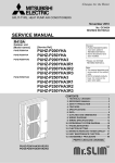
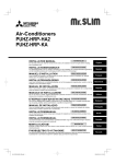
(3) The waveforms of remote controller communications
The following graphs are the examples for measuring waveforms on the wirings of remote controlled transmission at the
terminal block for remote controller.
a) A measuring example in the sequence of startup
b) A measuring example during normal stop
7.5
seconds
Transmission
from
remote
controller
7.5
seconds
Transmission
from
remote
controller
Transmission
from
indoor unit
Transmission
from
indoor unit
5V/div, 1sec/div:
5V/div, 1sec/div:
c) Expanded waveform 1 (signal 111000....)
d) Expanded waveform 2 (50kHz carrier)
5V/div, 10msec/div:
5V/div, 2μsec/div:
• During normal operation, the remote controller interactively exchanges signals with the indoor unit of refrigerant address “0”.
When the remote controller cannot receive signals from the indoor unit of refrigerant address “0” for 3 minutes, it is considered
as abnormal. E0 is displayed on the remote controller as an error.
5
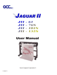
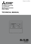
(4) The waveforms of communications between indoor and outdoor units
The following graphs are the examples for measuring waveforms on the wirings of connecting indoor and outdoor units at
between S2 and S3 of the outdoor terminal block TB1.
a) A measuring example the sequence of startup: 1
Transmission
from
indoor unit
b) A measuring example in the sequence of startup: 2
Transmission
from
outdoor unit
Transmission
from
indoor unit
10V/div, 500msec/div:
c) A measuring example during normal stop
(When 1 outdoor unit connects 1 indoor unit)
Transmission
from
indoor unit
Transmission
from
outdoor unit
10V/div, 500msec/div:
d) A measuring example during normal stop
(When 1 outdoor unit connects 2 indoor units)
Transmission
from
outdoor unit
Transmission
from
indoor unit
10V/div, 500msec/div:
Transmission
from
one indoor unit
Transmission
from
another
indoor unit
10V/div, 500msec/div:
e) Expanded waveform
10V/div, 50msec/div:
• During normal operation, outdoor unit interactively exchanges signals with all the connected indoor units.
• When outdoor unit cannot receive signals for 3 minutes from an indoor unit due to any trouble like cable disconnection, it is
considered as abnormal and the outdoor unit stops. E8 is displayed on the remote controller. This is to avoid independent
operation of indoor units.
6
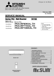
(5) Start-up system
A control unit is applicable to any models of standard (1:1), twin and triple without switch setting according to carrying out the
below process automatically when the power is supplied.
When the power is supplied, following processes of 1 Refrigerant address transmitting, 2 Power supply control to remote
controller, 3 Set number of the connected unit, 4 Set number of the indoor unit, 5 Duplication detection, 6 Collecting the unit
information and 7 Collecting the operation data are carried out as shown on the figure.
Also when detecting the duplicated setting in the step 5, back to the first step and reset it.
Power ON
; Transmitting the
switch setting
contents on the
outdoor unit remote
controller(SW1-3~6)
Refrigerant address
transmitting
Refrigerant
address "0"?
YES
Power supply control
to remote controller
NO
; Feeding control to
remote controller
Feeding the indoor
unit of the refrigerant
address “0”
Set number of the
connected unit.
Set number of the
indoor unit.
Duplication
detection
EA error if 4 minutes
have passed since
the power is supplied
; If there are 2 or more
specified indoor unit,
back to the first step
YES
Eb error if 4 minutes
have passed since
the power is supplied
NO
; Collecting the vane,
louver information and
transmittance to the
remote controller
Collecting the unit
information
; Collecting the
preceding operation
setting information and
transmittance to the
remote controller
Collecting the
operation data
Set up finish
EC error if 4 minutes
have passed since
the power is supplied
<<Feature>>
A. Start-up time from the second time will be shorter since setting of the number of connected units is memorized once set.
Start-up time can be estimated as following;
•When installing ... 1~2 minutes (Depending on the number of connecting units)
•Since the second time .... 20 seconds ~1 minute (Depending on the number of connecting units)
w When the above processing does not finish, even if 4 minutes have passed, consider the processing an error and
EA, Eb or EC will be displayed.
However if power is not supplied to the indoor unit due to miswiring or looseness of the connecting lines between
the indoor and outdoor unit, there will be no display on the remote controller. Also when the data cannot be
received from the outdoor unit, E6 is displayed on the remote controller after 6 minutes.
B. When replacing the P.C. board, only the unit number which has had its P.C. board replaced is reset.
Even if the power supply is reset, the unit number which has not had its P.C. board replaced does not change.
C. Automatic set unit is possible to confirm the unit number by blinking the frequency of LED3 in the indoor controller board.
At intervals of approx. 3 seconds, the number of the unit-number blinks.(Example:The unit(unit number:2) blinks twice at
3-second intervals.
Example
2 blinking
Not lighted
3 seconds
7
2 blinking
2-2. FUNCTION/ CONTROL SPECIFICATIONS
4-way ceiling cassette
Ceiling concealed
Item
PLA-RP·BA(2)
Notch
Fan
Function / specification
Drive method
Up/down
Direction setting
auto vane
Swing function
PEAD-RP·EA(2)
2 speed
2 speed
Tap-changing
Tap-changing
(AC motor)
(AC motor)
—
—
—
—
—
—
—
—
—
—
—
—
—
—
4 speed+Auto
Sinewave
drive
(DC motor)
5 direction *1 + Auto
(Heating mode : Wave-flow)
Shutter mechanism
Motor type
Pulse motor
(12V DC)
Left/right
Direction setting
swing louver
Motor type
Drain pump
PEAD-RP·GA
(Drain sesnsor)
(Float switch)
—
Note: The parts marked
are optional.
*1: Only using wired remote controller
(4 direction : Using wireless remote controller)
Wall mounted
Item
PKA-RP·FAL(2)
PKA-RP·GAL
Fan
Notch
Function / specification
Drive method
Up/down
Direction setting
auto vane
Swing function
4 speed
2 speed
Phase control
Phase control
(AC motor)
(AC motor)
4 direction
4 direction
Pulse motor
Pulse motor
(12V DC)
(12V DC)
(Manual operation)
(Manual operation)
—
—
Shutter mechanism
Motor type
Left/right
Direction setting
swing louver
Motor type
Drain pump
—
(Drain sensor)
Note: The parts marked
8
are optional.
3
INDOOR UNIT CONTROL
3-1. COOL OPERATION
Control modes
1. Compressor
Remarks
Control details
1-1. Thermoregulating function (Function to prevent restarting for 3 minutes)
• Room temperature
Set temperature +0.5···Compressor ON
• Room temperature Set temperature -1.5···Compressor OFF
+1 The thermoregulating
function is provided in the
outdoor unit.
The indoor unit transmits
the indoor room
temperature and set
temperature data to
outdoor unit, then the
outdoor unit controls
thermoregulation.
1-2. Anti-freezing control
Detected condition : When the liquid pipe temperature (TH2) or
condenser/evaporator temperature (TH5) (+2) is 2 or
less (+3) after 16 minutes from compressors start up,
anti-freezing control starts and the compressor will be
suspended.
Released condition : When any of the following conditions is satisfied,
antirepeat mode operates for 3 minutes and anti-freezing
control is released.
Liquid pipe temperature (TH2) and condenser/
evaporator temperature (TH5) turn 10 or above.
The condition of the compressor stop has become
complete by thermoregulating, etc.
The operation modes became mode other than COOL.
The operation stopped.
Anti-freezing operation is continued for 9 minutes.
1-3. Frozen protection
Detected condition : When the indoor pipe temperature (TH2) or
condenser/evaporator temperature (TH5) continues
-15 and below for 3 minutes since 3 minutes has
passed after the compressor start, the compressor stops
and then the mode changes to 6-minute stop restarting.
After restarting, the frozen protection (Error code : P6)
operates when either or condition is satisfied.
After 3 minutes of compressor start - up, pipe temp.
(TH2 or TH5) is lower than 15for 3 minutes.
After 16 minutes of compressor start - up, pipe
temp.(TH2 or TH5) is lower than –15.
Released condition : When the operation stops by the remote controller
operation.
2. Fan
By the remote controller setting (switch of 4 speeds+Auto or 4 speeds or 2 speeds)
Type
Fan speed notch
4 speeds+Auto
[Low] [Medium2] [Medium1] [High][Auto]
4 speeds
[Low] [Medium2] [Medium1] [High]
2 speeds
[Low]
[High]
When [Auto] is set, fan speed is changed depending on the value of:
Room temperature - Set temperature
9
+2 Compare liquid pipe
temperature to
condenser/evaporator
temperature, and the
lower one is applied to
anti-freezing control.
Liquid pipe
Liquid pipe Condenser/
Evaporator
temperature
temperature
Condenser/Evaporator pipe
Liquid pipe > Condenser/
Evaporator
temperature
temperature
+3 The function of
remote controller can
change the temperature
to start anti-freezing
control.
Control modes
3-1. Drain pump control
•Always drain pump ON during the COOL and DRY mode operation.
(Regardless of the compressor ON/ OFF)
•When the operation mode has changed from the COOL or DRY to the others
(including Stop), turn the drain pump ON for 3 minutes then stop the operation.
3-2. Liquid level detection method
Drain sensor type
• Energize drain sensor at a fixed voltage for a fixed duration. After energizing,
compare the drain sensor’s temperature to the one before energizing, and
judge whether the sensor is in the air or in the water.
· Drain sensor
Indoor controller
board
CN31 1
→
3. Drain pump
Remarks
Control details
2
3
Basic control
• While drain pump is turned on, repeat the following control system and judge · If the unit is
without the
whether the sensor is in the air or in the water.
drain sensor,
install the
ON
Timing of
jumper
energizing
·······Repeat
drain sensor
connector.
OFF
Indoor controller
Stand by for
30 sec.
Stand by for
30 sec.
board
1 minute
1 minute
1
CN31
→
Detect the
temperature
before
energizing(T0)
Detect the
temperature
after
energizing(T1)
Judge whether
the sensor is in
the air or in the
water.
•Drain sensor temperature rise (t)
•Temperature of drain sensor before current is applied (T0)
•Temperature of drain sensor after current is applied (T1)
[ t = T1 – T0 ]
2
3
· When
installing the
jumper
connector,
determine to
detect
compulsorily in
the air.
Float switch type
• Float switch control judges whether the sensor is in the air or in the water by
turning the float switch ON/OFF.
In the water
: Detected that the float switch is ON for 15 seconds.
In the air
: Detected that the float switch is OFF for 15 seconds.
Float SW
ON
OFF
15sec.
In the water
4. Vane
(up/down vane change)
15sec.
15sec. 1min.30sec.
In the air
In the water
1min.30sec.
Error
postponement
Drain pump
abnormal
(1) Initial setting :
When starting operation
: Horizontal ( Last setting may be applied
depending on the models.)
When changing operation mode : Horizontal
(2) Vane position :
Horizontal→Downward A→Downward B→Downward C→Downward D*1→Swing*1→Auto*1
(3) Restriction of the downward vane setting *2
When setting the downward vane A, B, C or D in [Medium2] or [Low] of the fan
speed notch, the vane changes to horizontal position after 1 hour have passed.
5. Louver
(Left/right change)
Remote controller setting
*1 Whether the unit
has a swing
function is listed in
the function/control
specifications.
· Downward,
Swing, Auto have
different functions
depending on the
models.
*2 "Only 1Hr"
appears on the
wired remote
controller.
Model which installed
louver function.
10
3-2. DRY OPERATION
Control modes
1. Compressor
Control details
Remarks
1-1. Thermoregulating function (Including the function to prevent restarting for 3 minutes)
Setting the compressor operation time by the thermoregulating signal
and the room temperature (TH1).
Thermoregulating signal ON Room temperature Set temperature +1
Thermoregulating signal OFF Room temperatureSet temperature
Room temp.
Range of
room temp.
Operating
time (min)
OFF time
(min)
28ti
26ti < 28
24ti < 26
ti < 24
—
9
7
5
3
3
3
3
3
3
10
Thermoregulating
signal
Over 18
ON
OFF
18 and below
The thermoregulating
function is provided in the
outdoor unit.
The indoor unit transmits
the indoor room
temperature and set
temperature data to
outdoor unit, then the
outdoor unit controls
thermoregulation.
Compressor operation stop
1-2. Anti-freezing control
No control function
2. Fan
1-3. Frozen protection
Same control as COOL operation
Indoor fan operation is controlled depends on the compressor conditions.
Compressor
Fan speed
ON
[Low]
OFF
Stop (*1)
Note: Remote controller setting is not acceptable.
3. Drain pump
*1 Note that even when
the compressor is OFF,
the unit starts operating in
[LOW] if the start condition
below is met.
Start condition:
The piping temperature
TH2 or TH5 has fallen to
1 or less.
Release condition:
The piping temperature
TH2 or TH5 has returned
to at least 10.
Same control as COOL operation
4. Vane
Same control as COOL operation
(up/ down vane change)
3-3. FAN OPERATION
Control modes
Control details
1. Compressor
None (always stopped)
2. Fan
Fan is controlled by remote controller setting.
Type
Fan speed notch
4 speeds+Auto
[Low] [Medium2] [Medium1] [High] [Auto]
4 speeds
[Low] [Medium2] [Medium1] [High]
2 speeds
[Low]
Remarks
[High]
When [Auto] is set, fan sped becomes [Low].
3. Drain pump
3-1. Drain pump control
Drain sensor type
The drain pump turns ON for the specified amount of time when any of the
following conditions is met.
ON for 3 minutes after the operation mode is switched from COOL or DRY to another
operation mode (FAN mode).
ON for 6 minutes after the drain sensor is determined to be submerged using the liquid
level detection method given below.
ON for 6 minutes after indoor liquid pipe temperature - indoor room temperature becomes
-10 or less AND the drain sensor input is at the short or open level. (If condition or is still being met after the drain pump has been turned ON for 6 minutes, the drain pump
is kept ON for a further 6 minutes.)
Float switch type
The drain pump turns ON for the specified amount of time when any of the following
conditions is met:
ON for 3 minutes after the operation mode is switched from COOL or DRY to FAN mode.
ON for 4 minutes after the float switch is submerged in the water when the float switch
control judges the sensor is in the water.
Continued to the next page
11
From the previous page
Control details
Remarks
3-2. Liquid level detection method
Drain sensor type
If any of the following conditions is met, liquid level detection is performed.
Drain pump is ON.
Indoor liquid pipe temperature - indoor room temperature -10(except
during defrosting)
Indoor liquid pipe temperature or indoor room temperature is at the short or
open level temperature.
Every 1 hour after the drain pump has been switched from ON to OFF.
Float switch type
• Float switch control judges whether the sensor is in the air or in the water
by turning the float switch ON/OFF.
In the water : Detected that the float switch is ON for 15 seconds.
In the air
: Detected that the float switch is OFF for 15 seconds.
Refer to “3-2. COOL
opration” for
liquid level detection
method.
Control modes
3. Drain pump
3-3. Detection of water leakage abnormality
Model : PLA-RP·BA
Conditions to detect water leakage abnormality
· When the float switch is detected to be in the water and drain switch turns to
ON from OFF under the operation other than cool or dry operation.
· Humidifier cannot be operated during water leakage abnormality delay.
· Abnormal (P5) when it is repeated twice that the drain pump is detected to
turn ON from OFF again within 1 hour after water leakage abnormality delay
Conditions to release water leakage abnormality delay
· When it is not detected that the drain pump is tuned ON from OFF within 1 hour
after detecting abnormality delay
· When the operation is changed to cooling or drying.
· Indoor liquid pipe temperature - indoor room temperature -10
Operation mode : When drain pump is detected to be ON and in the water except in the cooling and
drying operation
6 min.
Drain pump ON
OFF
ON
Float SW
OFF
15
sec.
In the water
Water leakage abnormality delay
15
sec.
6 min.
15
sec.
In the air
In the water
Within 1 h.
15
sec.
In the air
15
sec.
In the water
Water leakage abnormality
Within 1 h.
3-4. Forced compressor stop
Same control as heat operation
4. Vane
(up/ down
vane change)
Same as the control performed during the COOL operation, but with no restriction on the
vane's downward blow setting.
5. Louver
(Left/ right
change)
Remote controller setting
Model which installed
louver function.
12
3-4. HEAT OPERATION
Control modes
1. Compressor
Remarks
Control details
1-1. Thermoregulating function (Function to prevent restarting for 3 minutes)
• Room temperature Set temperature -1 ···Compressor ON
• Room temperature Set temperature +1···Compressor OFF
;1
The thermoregulating
function is provided in
the outdoor unit.
The indoor unit
transmits the indoor
room temperature and
set temperature data to
outdoor unit, then the
outdoor unit controls
thermoregulation.
1-2. Over-rise protection control
Detected control : When condenser/evaporator temp. (TH5) is higher than
70 and less than 90, compressor is stopped and mode is changed to
6-minute stop restarting mode.
After restarting, if condenser/evaporator temp. (TH5) is higher than 70
and less than 90 before 16 minutes passed, over- rise protection (Error
code : P6) operates.
Release control : When the operation stops by the remote controller
2. Auxiliary
heater
2-1. Thermoregulating function
When the mode is not hot adjust or Defrosting mode during heat
compressor operation, the controller changes to auxiliary heater ON.
Thermoregulating function follows the table below according to desired
temp. and room temp.
Temperature difference
Auxiliary heater
z<0
OFF
0 z < 3
Keeping condition
3z
ON
Models without
auxiliary heater also
control the units in the
same way as shown in
the left.
Temperature difference Z = Set temperature - Room temperature
2-2. Over-rise prevention control
When condenser/evaporator temp.(TH5) is higher than 60 during
compressor operation, auxiliary heater ON is prohibited as over - rise
prevention control. When the indoor condenser/evaporator temperature is
54 or less for 3 minutes during over-rise prevention, over-rise prevention
control will be released and auxiliary heater ON will be allowed. (However, in
case the condenser/evaporator temperature becomes 66 or more during
over-rise prevention, 40 or less will be required to release over-rise
prevention control and allow auxiliary heater to be ON.)
13
During the over-rise
prevention control,
"Fan speed up mode"
in the indoor fan is
controlled. (Only for
4-speed model)
Control details
Control modes
3. Fan
Remarks
By the remote controller setting (switch of 4 speeds+Auto or 4 speeds or 2
speeds)
Type
Fan speed notch
4 speeds+Auto
[Low] [Medium2] [Medium1] [High][Auto]
4 speeds
[Low] [Medium2] [Medium1] [High]
2 speeds
[Low]
Fan speed change
notch. Refer to the
model function table.
[High]
3-1. Hot adjust mode
3-2. Preheating exclusion mode
3-3. Thermostat OFF mode (When the compressor off by the thermoregulating)
3-4. Cool air prevention mode (Defrosting mode)
3-5. Fan speed up mode
3-1. Hot adjust mode
The fan controller becomes the stand by (hot adjust) mode for the following
conditions.
When starting the HEAT operation
When starting the compressor by the thermoregulating
When the HEAT defrosting operation is released
Hot adjust mode *1
Set fan speed by the remote controller
[Low]
*1 "STAND BY" will be
displayed during the
stand by (hot adjust)
mode.
[Extra Low]
A
B
C
A: Stand by (hot adjust) mode starts.
B: 5 minutes have passed since the condition A or the indoor Condenser/
Evaporator temperature turned 35 or more
C: 2 minutes have passed since the condition A.
(Terminating the stand by (hot adjust) mode)
3-2. Preheating exclusion mode
When the condition changes the auxiliary heater ON to OFF
(thermoregulating or operation stop, etc), the indoor fan operates in [Low]
mode for 1 minute.
This control is same for
the model without
auxiliary heater.
3-3. Thermo OFF mode
When the compressor stops by the thermoregulating, etc., the indoor fan
operates in [Extra low].
Fan speed can be
changed by setting the
function of remote
controller.
3-4. Cool air prevention mode (Heat defrosting mode)
After "hot adjust" mode is finished, the indoor fan will stop if the condition
mentioned below is detected. When receiving "DEFROST" from the
outdoor unit, the mode changes to defrosting mode.
"DEFROST "will be
displayed on the
remote controller
during the defrost
operation.
Pipe temp. (Condenser/Evaporator) - Room temp. -3
3-5. Fan speed up mode
•When the control changes to over-rise prevention
The condition of over-rise prevention (Prohibit for auxiliary heater ON)
continues for 10 seconds or more and the set fan speed is [Low] or
[Medium2], the fan speed changes to [Medium1].
•The fan speed up mode is released by canceling the over-rise prevention
mode.
14
This control is applied
for only
4-speed (+Auto) model.
Control details
Control modes
4. Drain pump
Remarks
4-1. Drain pump control
Drain sensor type
The drain pump turns ON for the specified amount of time when any of the
following conditions is met (regardless of whether the compressor is ON or OFF).
ON for 3 minutes after the operation mode is switched from COOL or DRY
to HEAT mode.
ON for 6 minutes after the drain sensor is determined to be submerged using
the liquid level detection method given below.
ON for 6 minutes after
indoor liquid pipe temperature - indoor room temperature
becomes -10 or less and the drain sensor input is at the short or open level.
(If condition or is still being met after the drain pump has been turned ON
for 6 minutes, the drain pump is kept ON for a further 6 minutes.)
Float switch type
The drain pump turns ON for the specified amount of time when any of the
following conditions is met:
ON for 3 minutes after the operation mode is switched from COOL or DRY
to HEAT mode.
ON for 4 minutes after the float switch is submerged in the water when the
float swich control judges the sensor is in the water.
Refer to “3-2. COOL
OPERATION” for
liquid level detection
method.
4-2. Liquid level detection method
Drain sensor type
If any of the following conditions is met, liquid level detection is performed.
Drain pump is ON.
Indoor liquid pipe temperature - indoor room temperature -10
(except during defrosting)
Indoor liquid pipe temperature or indoor room temperature is at the short or
open level temperature.
Every 1 hour after the drain pump has been switched from ON to OFF.
Float switch type
• Float switch control judges whether the sensor is in the air or in the water
by turning the float switch ON/OFF.
In the water : Detected that the float switch is ON for 15 seconds.
In the air
: Detected that the float switch is OFF for 15 seconds.
4-3. Detection of water leakage abnormality
Model : PLA-RP·BA
Conditions to detect water leakage abnormality
· When the float switch is detected to be in the water and drain switch turns to
ON from OFF under the operation other than cool or dry operation.
· Humidifier cannot be operated during water leakage abnormality delay.
· Abnormal (P5) when it is repeated twice that the drain pump is detected to
turn ON from OFF again within 1 hour after water leakage abnormality delay
Conditions to release water leakage abnormality delay
· When it is not detected that the drain pump is tuned ON from OFF within 1 hour
after detecting abnormality delay
· When the operation is changed to cooling or drying.
· Indoor liquid pipe temperature - indoor room temperature -10
Operation mode : When drain pump is detected to be ON and in the water except in the cooling and
drying operation
6 min.
Drain pump ON
OFF
ON
Float SW
OFF
15
sec.
In the water
Water leakage abnormality delay
15
sec.
6 min.
15
sec.
In the air
Within 1 h.
In the water
15
sec.
In the air
15
sec.
In the water
Water leakage abnormality
Within 1 h.
Continued to the next page
15
From the previous page
Control details
Control modes
Remarks
4. Drain pump
4-4. Forced compressor stop
· This detection is
The function is to stop the unit forcibly (System stopped) to prevent water
different from drain
leakage when the drain pump breaks down and the refrigerant leakage
pump abnormality.
occurs in the linear expansion valve.
Conditions to detect
When the following conditions are fully met (Always detected regardless of
whether the unit is ON or OFF)
Drain pump is ON.
Detected the following for 30 minutes (except during defrosting);
Indoor piping (liquid piping) temperature - room temperature -10
Detected to be in the water 10 times continuously (Drain sensor control)
Detected to be in the water for more than 15 minutes (Float switch control)
Control after detection
The compressor of the unit stopped forcibly is turned off and all the indoor
units are stopped. (Abnormality code: PA)
Conditions to release
Reset the power supply of the outdoor unit and indoor unit which caused the
anormality.
5. Vane control
(Up/ down vane
change)
(1) Initial setting : OFF ¡HEAT···[last setting]
When the last setting is [Swing] ··· [Swing]
When changing the mode from exception of HEAT to HEAT operation
···[Downward D or C]
(2) Vane position :
Horizontal ¡Downward A ¡Downward B ¡Downward C¡Downward D+1¡Swing+1¡Auto+1
(3) Determining position (When the timing motor of AC 200-240V)
Control each air outlet angle considering the starting OFF ¡ON of limit
switch to be a standard position (Horizontal or close).
When the standard position cannot be determined for 3 minutes, the vane
stops at the arbitrary position.
(4) Restriction of vane position
The vane is horizontally fixed for the following modes. (The control by remote
controller is temporally invalidated and the control by unit is validate.)
• Compressor OFF mode (Thermoregulating, etc.)
• Stand by (hot adjust) [Extra low] mode
• Heat defrost mode
• Piping (Condenser/Evaporator) temperature is 28 (+2) or less.
(5) Wave airflow control +3
When Swing is set, each vane runs independently and repeats horizontal
and down blows with a time lag.
Model: PLA-RP·BA (2)
+1 Whether the unit
has a swing
function is listed in
the function/control
specifications.
· Downward, Swing,
Auto have different
functions depending
on the models.
· See the
function/control
specifications for the
vane motor type.
+2 Changeable by unit
function setting
(mode 14) (Refer to
OUTDOOR UNITS
SERVICEMANUAL.)
+3 The vanes swing
simultaneously in
case of the function
setting without
waveflow control.
3-5. AUTO OPERATION
Control details
Control modes
Remarks
1. Initial value of HEAT mode for room temperature < Set temperature
operation mode COOL mode for room temperature Set temperature
· This mode is provided
in the outdoor unit. The
indoor unit follows the
instruction from the
outdoor unit.
2. Mode change (1) HEAT mode ¡ COOL mode
Room temperature Set temperature + 2 or 15 minutes has passed
(2) COOL mode ¡ HEAT mode
Room temperature Set temperature - 2 or 15 minutes has passed
· This mode is provided
in the outdoor unit. The
indoor unit follows the
instruction from the
outdoor unit.
3. COOL mode
Same control as cool operation
4. HEAT mode
Same control as heat operation
16
3-6. STOP OPERATION
Control modes
Control details
1. Drain pump
1.1 Drain pump control
Drain sensor type
The drain pump turns ON for the specified amount of time when any of the
following conditions is met (regardless of whether the compressor is ON or OFF)
ON for 3 minutes after the operation mode is switched from COOL or
DRY to another operation mode.
ON for 6 minutes after the drain sensor is determined to be submerged
using the liquid level detection method given below.
ON for 6 minutes after
indoor piping (liquid piping) temperature - room temperature -10,
and the drain sensor input is at the short or open level.
(If condition or is still being met after the drain pump has seen turned
ON for 6 minutes, the drain pump is kept ON for further 6 minutes.)
Float switch type
The drain pump turns ON for the specified amount of time when any of the
following conditions is met:
ON for 3 minutes after the operation mode is switched from COOL or
DRY to another operation mode.
ON for 6 minutes after the float switch is submerged in the water when
the float swich control judges the sensor is in the water.
Remarks
1.2 Liquid level detection method
Drain sensor type
The liquid level is detected by determining whether or not the drain sensor is
submerged, based on the amount the temperature rises after self-heating
the sensor. This process is performed if any of the following conditions is met.
Drain pump is ON.
Indoor piping (liquid piping) temperature - room temperature -10
(except during defrosting)
Indoor piping (liquid piping) temperature or room temperature is at the
short or open level temperature.
Every hour after the drain pump has been switched from ON to OFF.
Float switch type
Float switch control judges whether the sensor is in the air or in the water
by turning the float switch ON/OFF.
In the water : Detected that the float switch is ON for 15 seconds
In the air
: Detected that the float switch is OFF for 15 seconds
· Same control as cool
operation
1.3 Drain pump abnormality detection
Drain sensor type
· Abnormal (P5) when drain sensor detects to be in the water twice
Float switch type
· Abnormal (P5) when drain sensor judges to be in the water for 3 minutes
continuously (Float switch is ON.)
· It takes 3 minutes and
15 seconds to detect
abnormality including
the time that the
sensor judges to be in
the water first. time.
1.4 Float switch connector connection detection
Same control as cooling operation
· Models with float
switch
1.5 Water leakage abnormality detection
Same control as heating operation
1.6 Forced compressor stop
Same control as heating operation
17
3-7. SUPPLEMENTARY INFORMATION (UNIT FUNCTION SETTING)
(For setting, refer to OUTDOOR UNIT’S SERVICE MANUAL.)
1) Vane setting (Function setting mode11)
Model
Setting No.
PLA-BA(2)
Setting
1
Downward position than the standard (less smudging setting)
2
Standard position
3
Upward position than the standard (less draft setting) +
+Be careful of the smudge on ceiling.
2) Vane differential setting in heating mode (cold wind prevention) (Function setting mode14)
When piping temperature (TH5) becomes low during heating operation, the up/down vane is set to horizontal direction
for less draft setting. In this vane differential setting, the conditions of piping temperature to change airflow setting of
horizontal and setting shown below can be adjusted finely.
Setting airflow
Horizontal airflow
Piping temperature (TH5) ()
Setting 1 (low)
• • • 2428
Setting 2 (standard) • • • 2832
Setting 3 (high)
• • • 3238
18
4
OUTDOOR UNIT CONTROL
4-1. COOL OPERATION
Control modes
1. Compressor
Control details
Remarks
1-1. Thermoregulating function
The outdoor unit receives information of set temperature and intake
temperature from the indoor unit through transmission and judges the
necessity of thermoregulating from their temperature difference.
(Refer to “INDOOR UNIT CONTROL” for detailed detecting method.)
1-2. Normal control
Refer to “4-7.
Compressor operating frequency is controlled according to the difference
Inverter control”
between intake temperature and set temperature in order to let the intake
for “Inverter
temperature be the same as the set temperature
control basic
• Control timing: Once per minute after 3 minutes have passed since the
control
compressor started.
frequency
• Frequency changing range: -12Hz to +20Hz
setting”.
+ However, in the following cases, the frequency changing amount, which is
different from the normal one, will be applied to control the operating frequency.
(1) Frequency is fixed to the minimum just before the compressor is stopped
by the thermoregulating function.
Intake temperature Set temperature +0.5 ··· Fixed to the minimum frequency.
Intake temperature Set temperature +1.0 ··· Fixation is released. (Returned to normal control.)
(2) Correction of the frequency changing amount according to the estimated
discharge temperature If the estimated discharge temperature is more than
113, the frequency changing amount will be corrected.
• Correction amount: 0Hz to -6Hz
1-3. Start-up control
Controls, which are conducted in 3 minutes after the compressor gets started,
are categorized as below.
(1) In case of start-up (first time)
a. 0 min. to 1 min. after start-up: Fixed to 48Hz.
b. 1 min. to 3 min. after start-up: Fixed to the Hz which has been regulated
according to the temp. difference between intake temp. and set temperature
• Fixed frequency: minimum Hz to 48Hz.
(2) In case of restart
a. 0 min. to 1 min. after start-up: Fixed to 35 Hz.
b. 1 min. to 3 min. after start-up: Fixed to the Hz which has been regulated according
to the temperature difference between intake temp. and set temperature
• Fixed frequency: 35 Hz or 42Hz.
Maximum Hz will be controlled to 66Hz for 10 minutes after the start-up of compressor.
1-4. Indoor anti-freezing control
When the outdoor unit receives the signal of anti-freezing control mode, the
compressor stops. The compressor will restart when the indoor anti-freezing
control is released.
Refer to
“INDOOR UNIT
CONTROL” for
the indoor
anti-freezing
control.
1-5. Indoor frozen prevention control
Frequency controls such as Hz-down and no more Hz-up will be conducted
according to the indoor liquid pipe temp. (TH2) or indoor cond./eva. temp. (TH5).
Temp. restriction: No more Hz-up ··· When TH2 or TH5 detects 4.5 or less
··· When TH2 or TH5 detects 3.5 or less Hz-down
Hz-down amount: -5Hz per minute
Continued to the next page.
19
From the previous page.
Control modes
1. Compressor
Control details
Remarks
1-6. Discharge temperature over-rise prevention control
Frequency controls such as Hz-down and no more Hz-up will be conducted
according to the discharge temperature (TH4).
Temperature restriction: No more Hz-up ··· When TH4 detects 105 or more
Hz-down
··· -6Hz per min. when TH4 detects 110 or more
··· -10Hz per min. when TH4 detects 118 or more
1-7. Condensing temperature over-rise prevention control
Frequency controls such as Hz-down and no more Hz-up will be conducted
according to the outdoor 2-phase pipe temperature (TH6) (V/YHA),
pressure saturation temp. (T63HS) (V/YHA2)
Temperature restriction (TH6)
No more Hz-up
Hz down (-5 Hz per min.).
Hz down (-10 Hz per min.).
HRP71~125
56
58
61
+1 Thermistor (TH8)
1-8. Heatsink temperature over-rise prevention control +1
for HRP·YHA(2) is
Frequency controls such as Hz-down and no more Hz-up will be conducted
with built-in the
according to the heatsink temperature (TH8).
power-module.
Temperature restriction:
Models
PUHZ-HRP71V
Models
PUHZ-HRP100Y
No more Hz-up Hz-down
78
81
PUHZ-HRP100V
78
No more Hz-up Hz-down
88
91
88
PUHZ-HRP125Y
81
91
Hz-down amount: -5Hz per minute
1-9. Outdoor unit frozen protection control
If the cooling operation is continued for 16 hours, the compressor stops for
3 minutes.
2. Fan
2-1. Normal control
Fan rotation times (rpm) will be controlled according to the outdoor outside
temperature (TH7).
• Control method: Inverter control
• Rotation times: Fan step (N) = 0 and 2 to 10
• Compressor start-up: Fan step is fixed to 9 for 30 seconds after the
N=10
start-up of compressor.
N=9
N=8
N=7
N=6
N=5
N=4
N=3
N=2
-3
0
2
5
7
10 12
15 17
20 22
25 27
30 37
40
[]
Step (N)—Rotation
times(rpm)
<V/YHA>
Rotation times(rpm)
Step
(N) 71,100 125
0
1
2
3
4
5
6
7
8
9
10
0
105
130
145
190
240
285
360
465
700
720
0
125
155
175
200
240
285
360
465
700
720
Outside temperature (TH7)
<V/YHA2>
Rotation times(rpm)
Step
(N)
71, 100, 125
Fan step will be corrected according to the outdoor 2-phase pipe temp.(TH6) (V/YHA),
2-2. Correction of fan step according to the outdoor 2-phase pipe temperature
presuure saturation temp. (T63HS) (V/YHA2)
• Correction range of condensing temperature : 30 to 53
• Correction range of fan step: -1 to +3
2-3. Correction of fan step according to the heatsink temperature
Fan step will be corrected according to the heatsink temperature (TH8).
• Correction range of heatsink temperature: 68 to 74
• Correction range of fan step: 0 to +2
2-4. Other
Fan also stops when the compressor is being stopped. (Fan step = 0)
However, fan step will be set to 10 while the compressor is being stopped
due to the abnormal heatsink temperature (Error code = U5).
At this time, the compressor is just waiting for 3 minutes to restart.
20
0
1
2
3
4
5
6
7
8
9
10
0
100
125
140
185
220
275
370
450
680
700
Control modes
3. LEV(A)
Control details
Remarks
3-1. Normal control
Opening pulse will vary among steps (1 to 3) according to air conditioner’s
operating status.
• Control timing: Once every 5 minutes after 3 or 7 minutes have passed since
the compressor started.
• LEV opening pulse for each step:
Step
1
2
3
71
100
125
170
240
480
170
240
480
170
240
480
• Requirement for step-up
LEV opening pulse will step up when any of following conditions is satisfied.
(1) The discharge temperature (TH4) is 100 or more.
(2) V/YHA: The outdoor 2-phase pipe temperature (TH6) is 57 or more.
V/YHA2: The pressure saturation temp. (T63HS) is 63 or more .
(3) The discharge super heat temperature is 50 or more.
V/YHA: Super heat temperature = Discharge temperature (TH4) - Outdoor
2-phase pipe temperature (TH6)
V/YHA2: Super heat temperature = Discharge temperature (TH4) - Pressure
saturation temp. (T63HS)
(4) The sub cool temperature is 12 or more.
V/YHA: Sub cool temperature = Outdoor 2-phase pipe temperature (TH6)
- Outdoor liquid pipe temperature (TH3)
V/YHA2: Sub cool temperature = Pressure saturation temp. (T63HS)
- Outdoor liquid pipe temperature (TH3)
• Requirement for step-down
LEV opening pulse will step down when any of following conditions is satisfied
and any of step-up conditions are NOT satisfied.
(1) The discharge temperature (TH4) is 85~90 or less.
(2) V/YHA: The outdoor 2-phase pipe temperature (TH6) is 52 or less.
V/YHA2: The pressure saturation temp. (T63HS) is 57 or less.
(3) The discharge super heat temp. is 40 or less.
V/YHA: Super heat temperature = Discharge temperature (TH4) - Outdoor
2-phase pipe temperature (TH6)
V/YHA2: Super heat temperature = Discharge temperature (TH4) - Pressure
saturation temp. (T63HS)
(4) The sub cool temperature is 3 or less.
V/YHA: Sub cool temperature = Outdoor 2-phase pipe temperature (TH6)
- Outdoor liquid pipe temperature (TH3)
V/YHA2: Sub cool temperature = Pressure saturation temp. (T63HS)
- Outdoor liquid pipe temperature (TH3)
• The step does not change if neither step-up conditions nor step-down
conditions are satisfied.
3-2. Compulsory step-up
When any of the following conditions is satisfied, the step will be forced to 3.
(1) The discharge temperature (TH4) is 110 or more.
(2) V/YHA: The 2-phase pipe temperature (TH6) is 62 or more.
V/YHA2: The pressure saturation temp. (T63HS) is 65 or more.
3-3. Stop control
When the LEV is being stopped, the step will be set to 3.
21
Control modes
4. LEV(B)
Control details
Remarks
4-1. Normal control
LEV opening pulse will be controlled according to the change of compressor
operating frequency and regulated every minute to adjust the discharge
temperature to let the intake super heat temperature be 0 to 5.
• Control timing: Once per minute after 3 or 7 minutes have passed since the
compressor started.
• Opening pulse range: The following range is specified according to the
compressor operating frequency.
Compressor
frequency
49Hz or less
50Hz to 75Hz
76Hz to 90Hz
91Hz or more
Opening pulse range (Lower limit to upper limit)
100, 125
71
60 ~ 300
80 ~ 300
70 ~ 350
105 ~ 350
80 ~ 400
160 ~ 400
100 ~ 480
160 ~ 480
• Opening pulse range corresponding to the change of compressor operating
frequency
Opening pulse range = Present opening pulse (Target frequency/Operating
frequency -1) 0.8
• Compressor start-up
Opening pulse will be adjusted according to only the change of frequency
during 3 or 7 minute start-up. The start-up control time will be changed
according to the discharge temperature (TH4).
Discharge temperature (TH4) 30: 3 minute start-up
Discharge temperature (TH4) < 30: 7 minute start-up
4-2. Evaporation protection control
The targeted opening pulse should be made large in the condition written below.
Indoor cond./eva. temperature (TH5) - Indoor liquid pipe temperature (TH2)
3
Set the targeted value of the discharge temperature about 5 to 15 lower.
This control does not work for 3 or 7 minutes after the compressor gets started.
4-3. Low discharge super heat temperature protection control
Discharge super heat
temp. is calculated from
Set a small value for the targeted opening pulse according to the discharge
discharge temp. (TH4)
and outdoor 2-phase
super heat temperature.
pipe temp.(TH6) (V/YHA)/
• Correction range of the discharge super heat temp. : 10 or less
pressure saturation
This control does not work for 3 or 7 minutes after the compressor gets started. temp.(T63HS)(V/YHA2).
4-4. Others
LEV opening pulse is set to 400 while the compressor is being stopped.
After LEV opening pulse is initialized to 0 by making 700 pulse down from
the present pulse, set the pulse to 400.
20 pulses are added to the present pulse if the following conditions are
satisfied within 14 minutes after the compressor gets started.
COOL: Indoor 2-phase pipe temperature (TH5) - Indoor liquid pipe temperature (TH2) 25
HEAT: Outdoor 2-phase pipe temperature (TH6) - Outdoor liquid pipe temperature (TH3) 25
5. Four way valve
5-1. Normal control
Always OFF during normal operation.
5-2. Change of Operation mode
When the mode changes from HEAT to COOL:
Operation mode COOL
HEAT
Four way valve ON
OFF
22
4-2. HEAT OPERATION
Control details
Remarks
1-1. Thermoregulating function
The outdoor unit receives information of set temperature and intake temperature
from the indoor unit through transmission and judges the compressor ON/OFF
controlled by thermoregulating from their temperature difference. However, the
compressor does not stop when the indoor unit is in the hot adjuster mode even
though the information tells the need to turn off the compressor.
Refer to
“INDOOR UNIT
CONTROL” for
the detailed
detection
method.
Control modes
1. Compressor
1-2. Normal control
• Control timing: Once per minute after 3 minutes have passed since the
compressor started.
• Frequency changing range: -12Hz to +20Hz 1
1. However, in the following cases, the frequency changing amount, which is different
from the normal one, will be applied to control the operating frequency.
(1) Frequency is fixed to the minimum just before the compressor is stopped
by the thermoregulating function.
Intake temperature Set temperature - 0.5··· Fixed to the minimum frequency.
Intake temperature Set temperature - 1.0··· Fixation is released. (Returned to normal control.)
(2) Correction of the frequency changing amount according to the estimated
discharge temp.
If the estimated discharge temperature is more than 113, the frequency
changing amount will be corrected.
• Correction amount: 0Hz to -6Hz
(3) Frequency control after the defrosting operation
After the defrosting operation is finished, the compressor will be stopped
for 1 minute and then get restarted.
1-3. Start-up control
Controls, which are conducted in 3 minutes after the compressor gets started,
are categorized according to the outside temperature(TH7) as shown below.
Outside temp.
TH7 < 0
0 TH7 < 12
TH7 12
Start-up pattern
Initial start-up
Restart
(A)
(B)
(A)
(B)
(C)
(C)
Defrosting restart
(D)
(D)
(D)
(1) In case of pattern (A)
a. 0 min. to 1 min. after start-up: Fixed to 48Hz.
b. 1 min. to 3 min. after start-up: Fixed to the Hz which has been regulated
according to the temp. difference between intake temp. and set temp.
• Fixed frequency: minimum Hz to 48Hz.
(2) In case of pattern (B)
a. 0 min. to 1 min. after start-up: Fixed to the 35 Hz.
b. 1 min. to 3 min. after start-up: Fixed to the Hz which has been regulated
according to the temp. difference between intake temp. and set temp.
• Fixed frequency: 35 Hz or 42Hz.
(3) In case of pattern (C)
a. 0 min. to 3 min. after start-up: Fixed to 35 Hz.
(4) In case of pattern (D)
a. 0 min. to 1 min. after start-up: Fixed to the 70 Hz.
b. 1 min. to 3 min. after start-up: Fixed to the Hz which has been regulated
according to the temp. difference between intake temp. and set temp.
• Fixed frequency: 63 Hz or 70Hz.
Maximum Hz will be limited to 66Hz for 10 minutes after the start-up of compressor.
1-4. Discharge temperature over-rise prevention control
The same control as that of COOL operation.
Continued to the next page.
23
From the previous page.
Control details
Control modes
1. Compressor
Remarks
1-5. Condensing temperature over-rise prevention control
Frequency controls such as Hz-down and no more Hz-up will be conducted
according to the indoor cond./eva. temperature (TH5) (V/YHA) /the pressure
saturation temp. (T63HS) (V/YHA2).
<V/YHA>
Temperature restriction (TH5)
No more Hz-up
Hz down (-5 Hz per min.).
Hz down (-10 Hz per min.).
HRP71-125
51
56
61
stage-a
<V/YHA2>
stage-b
stage-c
stage-d
stage-e
stage-f
stage-g
-18 -17
-15 -14
-12 -11
-9
-8
-6
-5
-3
-2
Outside temperature (TH7) [ ]
Temperature restriction (T63HS)
HRP71 - 125
stage-a stage-b stage-c stage-d stage-e stage-f stage-g
No more Hz-up
Hz down (-5 Hz per min.)
Hz down (-10 Hz per min.)
2. Fan
61
63
64
60
62
64
59
61
63
58
60
62
57
59
61
55
57
59
49
51
53
2-1. Normal control
Fan rotation times (rpm) will be controlled according to the outdoor outside
temperature (TH7).
• Control method: Inverter control
• Rotation times: Fan step (N) = 0, 9 and 10
N=10
N: Current fan step
N=9
4
6
[]
Outside temperature (TH7)
Step (N)—Rotation times (rpm)
<V/YHA>
Rotation times (rpm)
Step
(N)
71,100
125
0
1
2
3
4
5
6
7
8
9
10
0
125
155
175
200
240
285
360
465
700
720
Step (N)—Rotation times (rpm)
<V/YHA2>
Rotation times (rpm)
Step
(N)
71, 100, 125
0
1
2
3
4
5
6
7
8
9
10
0
105
130
145
190
240
285
360
465
700
720
0
100
125
140
185
220
275
370
+
680
700
2-2. Start-up control in HEAT operation at low outside temperature
[Requirement] All of following conditions should be satisfied.
a. The first start-up after the power has been reset, or the start-up in HEAT
mode after 30 minutes have passed since the compressor stopped.
b. Outside temperature (TH7) 0
[Control details]
Fan step will be set to 0 (N = 0) for 2 minutes after the start-up of compressor.
Start-up control will turn into the normal control after the 2-minute operation of compressor.
2-3. Others
Fan also stops when the compressor is being stopped. (Fan step = 0)
However, fan step will be set to 10 while the compressor is being
stopped due to the abnormal heat sink temperature (Error code = U5).
At that time, the compressor is just waiting for 3 minutes to restart.
24
+ Cooling : 450
Heating : 500
Control modes
3. LEV(A)
Control details
Remarks
3-1. Normal control
<Without INJ>
LEV opening pulse will be controlled every minute to adjust the discharge
temperature in order to let the intake super heat be 0 to 5.
• Control timing: Once per minute after 3 or 7 minutes have passed since
the compressor started.
• Opening pulse range: The following range is specified according to the
compressor operating frequency.
Compressor
frequency
49Hz or less
50Hz to 75Hz
76Hz to 90Hz
91Hz to more
Opening pulse range (Lower limit to upper limit)
71 (V/YHA)
100, 125 (V/YHA) 71,100,125 (V/YHA2)
80 ~ 300
60 ~ 300
55 ~ 300
85 ~ 350
70 ~ 350
60 ~ 350
100 ~ 400
80 ~ 400
70 ~ 400
130 ~ 480
100 ~ 480
90 ~ 480
• Opening pulse range corresponding to the change of compressor operating
frequency
Opening pulse range = Present opening pulse % (Target frequency/
Operating frequency -1) % 0.8
• Compressor start-up
Opening pulse will be adjusted according to only the change of frequency
during 3 or 7 minute start-up.
The start-up control time will be changed according to the discharge
temperature (TH4).
Discharge temperature (TH4) 30: 3 minute start-up
Discharge temperature (TH4) < 30: 7 minute start-up
<With INJ>
Ajdust the discharge temperature in order to let the intake super heat temperature be around 10.
• Control timing: 2 | ∆SH |
······Once per minute
1 | ∆SH | < 2 ······Once per 2 mitutes
| ∆SH | < 1 ······No change
• Variation for each time: 0~20 pulse
3-2. Low discharge super heat temperature protection control
Set a small value for the targeted opening pulse according to the discharge
super heat temperature.
• Correction range of the discharge super heat temperature : 10 or less
• This control does not work for 3 or 7 minutes after the compressor gets started.
3-3. Evaporation protection control
20 pulse will be added to the present opening pulse in the condition written below.
Outdoor 2-phase pipe temperature (TH6) - Outdoor liquid pipe
temperature (TH3) 6
This control does not work for 3 or 7 minutes after the compressor gets started.
3-4. Others
LEV opening pulse is set to 400 while the compressor is being stopped.
After LEV opening pulse is initialized to 400 by making 700 pulse down from
the present pulse, set the pulse to 400.
25
∆SH = Intake
super heat -10.
Discharge super heat
temp. is calculated from
discharge temp. (TH4)
and outdoor 2-phase pipe
temp. (TH6) (V/YHA)/
pressure saturation temp.
(T63HS) (V/YHA2).
Control modes
4. LEV(B)
Remarks
Control details
4-1. Normal control
Opening pulse will vary among steps (1 to 3) according to air conditioner’s
operating status.
• Control timing: Once every 5 minutes after 3 or 7 minutes have passed since
the compressor started.
• LEV opening pulse for each step:
Step
71
100
125
1
2
3
140
220
480
140
220
480
140/150
220
480
• Start-up step
The step is set to 2 when the compressor starts up.
• Requirement for step-up
LEV opening pulse will step up when any of following conditions is satisfied.
(1) The discharge temp. (TH4) is 100 or more.
(2) V/YHA: The indoor 2-phase pipe temperature (TH5) is 57 or more.
V/YHA2: The pressure saturation temp. (T63HS) is 63or more.
(3) The discharge super heat temperature is 50 or more.
V/YHA: Super heat temperature = Discharge temperature (TH4) - Indoor
2-phase pipe temperature (TH5)
V/YHA2: Super heat temperature = Discharge temperature (TH4) - Pressure
saturation temp. (T63HS)
(4) The sub cool temperature is 12 or more.
V/YHA: Sub cool temperature = Indoor 2-phase pipe temperature (TH5) - Indoor
liquid pipe temperature (TH2)
V/YHA2: Sub cool temperature = pressure saturation temp. (T63HS) - Indoor liquid
pipe temperature (TH2)
• Requirement for step-down
LEV opening pulse will step down when any of following conditions are
satisfied and above step-up conditions are not satisfied.
(1) The discharge temperature (TH4) is 85~90 or less.
(2) V/YHA: The indoor 2-phase pipe temperature (TH5) is 52 or less.
V/YHA2: The pressure saturation temp. (T63HS) is 57 or less.
(3) The discharge super heat temperature is 40 or less.
V/YHA: Super heat temperature = Discharge temperature (TH4) - Indoor
2-phase pipe temperature (TH5)
V/YHA2: Super heat temperature = Discharge temperature (TH4) - Pressure
saturation temp. (T63HS)
(4) The sub cool temperature is 3 or less.
V/YHA: Sub cool temperature = Indoor 2-phase pipe temperature (TH5)
- Outdoor liquid pipe temperature (TH3)
V/YHA2: Sub cool temperature = Pressure saturation temp. (T63HS) - Outdoor
liquid pipe temperature (TH3)
• The step does not change if neither step-up conditions nor step-down
conditions are satisfied.
4-2. Compulsory step-up
When any of the following conditions are satisfied, the step will be forced to 3.
(1) The discharge temperature (TH4) is 110 or more.
(2) V/YHA: The 2-phase pipe temperature (TH6) is 62 or more.
V/YHA2: The pressure saturation temp. (T63HS) is 65or more.
4-3. Stop control
When the LEV is being stopped, the step will be set to 3.
26
Control modes
5. LEV(C)
Control details
6-1. Requirement for starting INJ
INJ starts when all of the following conditions are satisfied.
(1) The outdoor outside temp. (TH7) is 3 or less.
(2) The compressor frequency is 65Hz or more.
(3) The condensation temperature (Indoor 2-phase pipe temp. (TH5) (V/YHA)/
Pressure saturation temp. (T63HS) (V/YHA2)) is 56 or less.
(4) Having no abnormal delay.
6-2. Starting step
Discharge super heat 30
30 Discharge super heat < 30
Discharge super heat 20
step4
step3
step1
6-3. Normal control
Discharge super heat 30
20 < Discharge super heat 30
10 Discharge super heat 20
Discharge super heat < 10
2 steps up
1 step up
keep the step
1 step down
6-4. Requirement for ending INJ
INJ finishes when any of the following conditions are satisfied.
(1) Operation stop or mode change
(2) After 30 minutes, the outdoor outside temp. (TH7) 4
(3) The compressor frequency is less than 60Hz.
(4) The condensation temperature (Indoor 2-phase pipe temp. (TH5) (V/YHA)/
Pressure saturation temp. (T63HS) (V/YHA2)) is 61or less.
Opening pulse is set to 5 when INJ finishes.
6. Four way valve
Remarks
7-1. Normal control
Always OFF during normal operation.
7-2. Change of Operation mode
• When the mode changes from HEAT to COOL:
Operation mode COOL
HEAT
Four way valve ON
OFF
• When the operation stops in HEAT mode:
Operation mode HEAT
Stop
Four way valve ON
OFF
10 minute
7-3. Start-up control in HEAT operation at low outside temperature
[Requirement] Same as the explanation in fan control.
[Control details] OFF for 2 minutes after the start-up of compressor, but ON if 2
minutes pass.
7-4. In the defrosting operation
Always OFF during the defrosting operation
27
Step
0
1
2
3
4
5
6
7
8
HRP71~125
5
70
100
150
200
250
300
400
460
4-3. DRY OPERATION
Control modes
1. Compressor
Control details
1-1. Thermoregulating function
The outdoor unit receives information of set temp. and intake temp. from the
indoor unit through transmission and judges the compressor ON/OFF with
thermoregulating function from their temperature difference.
1-2. Normal control
Same control as that of COOL operation.
1-3. Start-up control
Same control as that of COOL operation.
1-4. Indoor anti-freezing control
Not available
1-5. Outdoor frozen prevention control
Same control as that of COOL operation
1-6. Discharge temperature over-rise prevention control
Same control as that of COOL operation
1-7. Condensing temperature over-rise prevention control
Same control as that of COOL operation
1-8. Heatsink temperature over-rise prevention control
Same control as that of COOL operation.
1-9. Others
Same control as that of COOL operation.
2. Fan
2-1. Normal control
Fan rotation times (rpm) will be controlled according to the outdoor outside temp. (TH7).
• Control method: Inverter control
• Rotation times: Fan step (N) = 0 and 2 to 10
• Comp. Start-up: Fan step is fixed to 9 for 30 seconds after the start-up of compressor.
2-2. Correction of fan step according to the outdoor 2-phase pipe temperature
Fan step will be corrected according to the outdoor 2-phase pipe temperature (TH6).
• Correction range of condensing temperature : 30 to 53
• Correction range of fan step: -1 to +3
2-3. Correction of fan step according to the heatsink temperature
Fan step will be corrected according to the heatsink temperature (TH8)
• Correction range of heatsink temperature: 68 to 78
• Correction range of fan step: 0 to +2
2-4. Others
Fan also stops when the compressor is being stopped. (Fan step = 0.)
However, fan step will be set to 10 while the compressor is being stopped due
to the abnormal heatsink temperature (Error code = U5). At this time, the
compressor is just waiting 3 minutes to restart.
3. LEV
The same control as that of COOL operation.
4. Four way valve
4-1. During normal operation
Always OFF during normal operation.
4-2. Operation mode change
When the mode changes from HEAT to COOL;
Operation mode COOL
HEAT
Four way valve ON
OFF
28
Remarks
Refer to “INDOOR
UNIT CONTROL”
for ON/OFF
judgment method
4-4. FAN OPERATION
Control modes
Control details
Remarks
Control details
Remarks
1-1. Requirements for starting
Defrosting starts whe any of the following conditions is satisfied.
(Conditions)
a. In HEAT operation and when the outdoor liquid pipe temp. (TH3) continues to
be -2 or less for 7 minutes after the compressor integrating operation time
fulfils defrosting prohibition time (т1 +).
b. In HEAT operation and when the outdoor liquid pipe temp. (TH3) continues
be -5 or less and TH7 - 10 or less after the compressor integrating
operation time fulfils defrosting prohibition time (т3 +).
c. In HEAT operation and when the outdoor liquid pipe temp. (TH3) continues to
be -2 or less for 7 minutes after the compressor integrating operation time
fulfils the defrosting prohibition time (т1 +) and the compressor stops twice
within 10 minutes from its start-up.
+ Refer to the
table of “Defrosting
prohibition time т1,
т3” on this page.
1. Compressor
Always OFF
2. Fan
Always OFF
3. Four way valve
Always OFF
4-5. DEFROSTING OPERATION
Control modes
1. Start
(Complementary explanation)
The (a) indicates the defrosting operation with the light frost amount .
The (b) indicates the defrosting operation with the heavy frost amount.
The (c) indicates the defrosting operation in case the thermostat is turned ON/OFF
frequently because the frost amount is small and the air-conditioning load is light.
1-2. Actuator at the beginning of defrosting operation
+Defrosting operation
Activate the actuator by the following procedure if any of the above conditions is frequency
Model Frequency
detected.
name
71~125 92Hz
Let compressor operating frequency down to 30Hz.
When the compressor operating frequency becomes 30Hz;
• Turn off the four way valve.
• Stop the outdoor fan.
• Set LEV A and B opening pulse to 480 and LEV C to 200.
After and are completed, the compressor will be set to the defrosting
operation frequency+.
2. Stop
2-1. Requirements for ending
Defrosting stops when any of the following conditions is satisfied.
(Conditions)
a. 15 minutes have passed since the defrosting operation started.
b. The outdoor liquid pipe temperature (TH3) has become 20 or more within 2
minutes from the start of defrosting operation.
c. The outdoor liquid pipe temperature (TH3) has become 8 or more after the
defrosting operation is conducted for 2 minutes.
d. During defrosting operation, the compressor has been stopped due to errors
or something.
e. During defrosting operation, the operation mode except HEAT has been
selected by remote controller.
Continued to the next page.
29
From the previous page.
Control modes
2. Stop
Control details
Remarks
2-2. Actuator at the end of defrosting operation
Activate the actuator by the following procedure if any of the above conditions
except d & e is detected.
Start the outdoor fan.
Let the compressor operation frequency down to 30Hz from the defrosting
operation frequency.
Stop the compressor for 1 minute when the compressor operation frequency
becomes 30Hz.
After to are completed, set the compressor operation frequency to the
normal (start-up pattern A).
3. Defrosting prohibition
time
Defrosting prohibition time (т1 and т3) are decided by the set contents of defrosting
control and the previous defrosting operation time (т2).
• Prohibition time table for standard region
Previous operation time
т1
Prohibition time
т3
30 minutes
20 minutes
20 minutes
20 minutes
20 minutes
т2 3 minutes
150 minutes
3 < т2 7 minutes
90 minutes
7 < т2 10 minutes
50 minutes
10 < т2 15 minutes
30 minutes
т2 = 15 minutes
20 minutes
• Prohibition time table for high humidity region
Previous operation time
т2 7 minutes
7 < т2 15 minutes
т1
Prohibition time
50 minutes
20 minutes
т3
20 minutes
20 minutes
• Others
Prohibition time
т1
т3
Operation mode has been changed to the other mode 90 minutes 40 minutes
except HEAT during defrosting operation.
Protection devices have worked during defrosting operation. 10 minutes 10 minutes
90 minutes 40 minutes
Initial prohibition time when power is reset.
4. Forced defrosting
4-1. Requirements for starting
Compulsory defrosting operation will be conducted if all conditions below are
satisfied when SW1-1 (OFF → ON) is detected during HEAT operation.
(Conditions)
a. The compressor is operating.
b. 10 minutes have passed since the compressor started or the last defrosting
operation was conducted.
c. The outdoor liquid pipe temperature (TH3) is less than 8.
4-2. Requirements for ending
The same conditions as the above ending conditions of normal defrosting
30
4-6. AUTO OPERATION
Control modes
Control details
Remarks
1. Initial operation mode When a operation mode turns into AUTO operation;
HEAT mode will be operated if intake temperature < set temperature
COOL mode will be operated if intake temperature
2. Change of
operation mode
set temperature
HEAT mode will turn into COOL mode when intake temperature set temperature + 2deg
and 15 minutes have passed since the HEAT operation started.
COOL mode will turn into HEAT mode when intake temperature set temperature – 2deg
and 15 minutes have passed since the COOL operation started.
3. COOL mode
The same controls as those of COOL operation.
4. HEAT mode
The same controls as those of HEAT and defrosting operation.
4-7. INVERTER CONTROL
Control modes
1. Basic control
1-1. Frequency setting
PLA-RP·BA (2)
MAX
RATED
36
61
39
64
51
76
53
80
69
98
67
91
min
71V
100V/Y
125Y
Remarks
Control details
COOL
HEAT
COOL
HEAT
COOL
HEAT
25
25
25
25
25
25
PEAD-RP·EA (2)
RATED
MAX
38
61
40
64
51
76
53
80
70
98
66
91
PEAD-RP·GA
MAX
RATED
38
61
41
64
55
76
56
80
—
—
—
—
PKA-RP·FAL
MAX
RATED
—
—
—
—
57
76
55
80
—
—
—
—
1-2. V/F pattern
PUHZ-HRP100,125YHA (2) 1
250
500
200
400
Voltage (V)
Voltage (V)
PUHZ-HRP71,100VHA (2) 1
150
100
50
300
200
100
0
0
50
100
150
0
Operating frequency (Hz)
100
150
0
50
Operating frequency (Hz)
1. Actual performance does not exactly match the V/F line on both graphic charts due to
the air-conditioning load because the inverter control is based on vector.
2. Frequency
2-1. Frequency is restricted by the compressor electrical current (CT1).
Frequency control such as Hz-down and no more Hz-up will be conducted
according to the compressor electrical current (CT1).
No more Hz-up
Hz-down
PUHZ-HRP71, 100VHA
24.5A
26A
PUHZ-HRP100, 125YHA
16A
17A
PUHZ-HRP71, 100VHA2
24.5A
26A
PUHZ-HRP100, 125YHA2
19A
20A
Models
3. Voltage correction
3-1. Voltage is corrected by bus voltage.
Inverter voltage will be corrected by dc bus voltage.
Even though the power supply voltage varies within $10%, the voltage should
be corrected in order to make the output voltage of inverter stable.
31
+ Hz-down amount:
-5Hz per minute
Control modes
4. Power supply to
locked compressor
Control details
Remarks
“08” will be
displayed on the
LED1 of “A-Control
Service Tool” while
power is supplied to
the compressor.
4-1. Compressor energizing method
• Compressor ON/OFF pattern when power is supplied;
4hrs
ON
30 min.+
30 min.
+ Repeated
+
Outdoor temp.21
OFF
30 min.
30 min.
30 min.
Power supply
Energized the outside
temperature is 21 or less Outdoor temp.>21
Cycle :
15 min. ON
30 min. OFF
• Compressor ON/OFF pattern when power is cut off;
ON
OFF
30 min.+
30 min.
30 min.
+ Repeated
30 min. 30 min.
OFF
Comp. stopped
5. 52C
30 min.
30 min.
ON/OFF method
52C will turn ON/OFF in the following conditions.
• 52C turns ON when power is supplied, and remains ON regardless of the
compressor’s ON/OFF.
• 52C turns OFF when power is cut off.
4-8. REPLACEMENT OPERATION
Control modes
1. Start and end of
replacement
operation
Control details
Remarks
1-1. Requirements for starting
Replacement operation will start when SW8-2 on the outdoor controller board
is turned on while units are being stopped.
1-2. Requirements for ending
Replacement operation will end if any of the following condition is satisfied.
a. 2 hours have passed since replacement operation started.
b. SW8-2 has been turned off.
c. Operation (COOL/DRY/HEAT) has been started and controlled by remote
controller.
2. During replacement 2-1. Normal control
operation
In COOL operation replacement operation will be conducted by opening the
replacement filter circuit in order to circulate refrigerant.
• Compressor control
The same continuous operation as COOL operation regardless of intake temperature.
• LEV(A) control
Alaways closed.
• LEV(B) control
The same operation as that of COOL operation.
• LEV(C) control
Alaways closed.
• Fan control
The same operation as that of COOL operation.
• Four way valve control
The same operation as that of COOL operation. (Always OFF.)
• Solenoid valve
Always opened.
• Others
LED on the outdoor controller circuit board comes ON/OFF per second during
replacement operation.
+ Normal air
conditioning can be
operated even if
SW8-2 remains ON
after the replaement
operation is
finished.
+ Cold air comes
out of indoor unit
because the
replacement
operation is
conducted in
COOL operation.
Continued to the next page.
32
From the previous page.
Control modes
2. During replacement
operation
Control details
2-2. Indoor frozen prevention control
The compressor will be stopped for 3 minutes if the indoor liquid pipe
temperature (TH2) or indoor condenser/evaporator temperature (TH5) is
3 or less after 10 minutes have passed since the compressor started.
Remarks
+ Frozen protection
control may be
activated when the
indoor intake temp.
is 15 or less.
4-9. REFRIGERANT COLLECTING (pump down)
Control modes
Control details
Remarks
1. Start and end of pump 1-1. Requirements for starting
Pump down operation will be conducted when SWP on the outdoor controller
down operation
board is turned on while the unit is being stopped.
1-2. Requirements for ending
Pump down operation will end if any of the following conditions is satisfied.
a. Low pressure switch has been used.
b. 3 minutes have passed since the pump down operation started.
c. Operation has been stopped by remote controller or changed to the other
mode except COOL.
d. Error has been detected.
2. During pump down
operation
2-1. Following controls are activated during pump down operation.
• Compressor control
The same continuous operation as COOL operation regardless of intake
temperature.
• LEV (A) control
Opening pulse is fixed to step 3 (480 pulse).
• LEV (B) (C) control
Completely closed (0 pulse).
• Fan control
Fan step is fixed to step 10.
• Four way valve
OFF in COOL operation.
<Complementary
explanation for
above 2 controls>
Pump down operation is considered to be finished normally when the ending
To prevent the
condition (a) or (b) is satisfied.
unit from
At this time, the outdoor controller board’s LED1 (green) turns OFF and LED2
operating with
(red) turns ON. The unit cannot be operated until the power is reset.
pump down
If the pump down operation ends due to the ending conditions (c) or (d), the unit
will be in a state of normal stop.
33
operation.
5
SYSTEM CONTROL
5-1. VARIETY OF SYSTEM CONTROL FUNCTIONS
System Name
A.Remote controller operation
(Standard)
System Diagram
Indoor unit
Outdoor
unit
Indoor
unit
B.Remote controller operation
Use of 2
controllers
enables
operation of the
air conditioner
both from a
distance and
nearby.
Remote
Controller
Remote
Controller
* One of the wired remote controllers must be set as a sub
remote controller.
C.Group control
operation
Use of 1 remote
controller to
control multiple
air conditioners
with the same
settings
simultaneously.
Indoor
unit
Outdoor
unit
Remote
Controller
Features
Parts Required in addition to Standard System
Components (Indoor/Outdoor Units, Remote Controller)
• There are 2 types of remote controllers:
Wired type and wireless type.
• Simultaneous twin, triple units are counted as 1
unit, and the indoor units are started or stopped
simultaneously.
• Up to 2 remote controllers can be connected to
1 group.
• Simultaneous twin units are counted as 1 unit.
• Operation control by the latest command (last entered priority)
• Wired and wireless remote controllers can be
combined as a pair.
• 1 group can consist of up to 16 indoor units, and
they can be started sequentially by connecting the
remote controller to them and assigning an address
to each unit.
• Simultaneous twin units are counted as 1 unit.
• All the units belonging to the same group are operated in the same mode, but thermostats can be
turned ON/OFF individually for each outdoor unit.
• Up to 2 remote controllers can be connected.
Wired remote controller (additional)
(PAR-21MAA)
For models PKA-RP·FAL/GAL
use remote controller
(PAR-21MAAT-E).
* For models equipped with a terminal block.
For models PKA-RP·FAL/GAL
use remote controller
(PAR-21MAAT-E).
* For models equipped with a terminal block.
* Outdoor unit's
refrigerant address needs to
be set.
• All the air conditioners can be turned ON/OFF
collectively from a distance.
• Operation can be switched between the remote
operating panel and local controller.
• Operations (e.g., temperature adjustment, airflow,
airflow direction) except for start/stop operations
can be performed even if the remote controller is
being operated.
• In the case of simultaneous twin, triple units,
connect the controller to 1 indoor unit only. If connected to 2 or more indoor units, an error
(operation stop) may occur.
• Control by an external timer is possible by
connecting it.
Remote ON/OFF adapter
(PAC-SE55RA-E)
Relay box
(Part to be provided locally)
Remote operating panel
(Part to be provided locally)
E.Operation by
external signal
• Use of optional "remote ON/OFF adapter" enables
remote control via relay. (Level signal)
Remote ON/OFF adapter
(PAC–SE55RA-E)
F.Control and remote
display by external
signal (extraction
of monitor signal)
Extraction of non-voltage contact output
• Use of optional "remote operation adapter" and
"remote display panel" (Part to be provided locally)
provides non-voltage contact outputs of signals
(operation, error) and operation/stop input
function.
Remote operation adapter
(PAC-SF40RM-E)
Remote display panel
(Part to be provided locally)
Extraction of DC12 V contact output
• Use of optional "multiple remote controller
adapter" and "remote display panel" (Part to be
provided locally) provides DC12 V contact
outputs of signals (operation, error) and operation/
stop input function.
Multiple remote controller adapter
(PAC-SA88HA)
Remote display panel
(Part to be provided locally)
D.Remote/local
combined control
operation
Allows start/stop
of the air
conditioner from
a distance, and
prohibits/permits
start/stop from
remote
controllers.
Enables you to
display the
operation state
and control
start/stop from a
distance.
Relay box
Indoor unit
Remote Controller
Remote operating panel
Adapter
Indoor unit
Remote Controller
Remote display panel
(operation, error)
34
System Name
System Diagram
• Weekly timer:
In addition to ON/OFF, up to 8 temperature
patterns can be set for each day of the week.
*Only 1 timer can be selected; the auto off, simple
and weekly timers cannot be combined.
• Simple timer: Start and stop operations can each
be performed once within 72 hours
(can be set in 1-hour increments).
• Auto off timer:Operation is stopped when the preset
time elapses following the start of
operation.
The time can be set from 30 minutes
to 4 hours in 30-minute increments.
*Only 1 timer can be selected; the simple and auto
off timers cannot be combined.
G. Timer operation
Enables control
of start and stop.
* For control by
external timer,
refer to Remote/
local combined
control operation".
H.Interlock operation with peripheral equipment
Features
Indoor unit
Lossnay
ventilator
Enables control of
Mitsubishi Lossnay
ventilator by remote
controller.
Remote
Controller
<Connection with M-NET system>
Outdoor
unit
Power
supply
unit
Indoor
unit
I.Central control
Remote
Controller
Central controller, etc.
Adapter to input
external demand
signal
J.Demand control
Relay box
Outdoor unit
Parts Required in addition to Standard System
Components (Indoor/Outdoor Units, Remote Controller)
MA Remote controller
(PAR-21MAA)
• Connecting a Lossnay ventilator and an indoor unit
enables control of interlock/solo ventilation
operation and airflow.
(Only the microcomputer type Lossnay ventilator
can be used.)
• Connecting the M-NET connection adapter to indoor
unit enables connection of MELANS system
controller (for M-NET).
• When using A-control operation, the number of
indoor units in a MELANS system is limited to the
number of outdoor units.
(Simultaneous twin, triple units are counted as 1
unit.)
• Number of controlled outdoor units
Central controller: 50 units
Group remote controller
(PAC-SC30GR): 16 units
M-NET adapter (Option PARTS)
Central controller
(G-50A)
Group remote controller
(PAC-SC30GR), etc.
• Demand control is available by external input. In
this mode, power consumption is decreased
within the range of usual 0-100%.
Adapter to input external
demand signals (PAC-SC36NA)
Relay box
(Part to be provided locally )
Remote operating panel
(Part to be provided locally)
Remote
Operating panel
K.Rotation
Indoor unit
• Rotation
Main and sub unit operate alternately according
to the interval of roration setting.
• Back-up
When abnormality occurs while operation, it
changes into operating the backup unit, and
operation is continued.
• 2nd stage cut-in
· Number of operating units is determined
according to the room temperature and set point.
· When room temperature becomes higher than set
point, standby unit starts. (2 units operation)
· When room temperature falls below set point
-4°C, standby unit stops. (1 unit operation)
35
This function is available when
only 2 indoor units are
connected to each PUHZ type
outdoor unit.
Application model
Indoor unit
PLA-RP • BA2/BA#2.UK
PCA-RP • GA(2)#1/HA#1
PKA-RP • GAL#1/FAL(2)#1
PSA-RP • GA#1
PEAD-RP • EA(2)#1/GA#1
5-2. 1 REMOTE CONTROLLER (STANDARD) OPERATION
(1) 1 Wired Remote Controller
(OC: Outdoor unit IC: Indoor unit
R: Remote controller (for wireless type: Receiver)
Slim Air Conditioners System
Standard 1:1
Outdoor unit
OC
System diagram
(Wired remote
controller)
Indoor/Outdoor
connection
cable
Indoor unit
IC
Remote
controller
cable
Wired
remote
controller R
Simultaneous Twin
OC
OC
3
3
IC-1
3
IC-1 IC-2
2
2
R
R
(Reference)
1 If simultaneous twin, connect the remote controller to an indoor unit. All functions of the indoor unit can be controlled
even if different models (different types) are mixed. Note that there may be some restrictions of the functions.
2 Do not use crossover wiring among indoor units with simultaneous twin units. (Prohibited item.)
3 Electrical wiring diagram
Outdoor unit
Power
source
wiring
Indoor unit
IC
OC
L1
L2
L3
N
Remote controller
S1
S2
S3
S1
S2
S3
(Polarity)
• Power supply terminal block L1, L2, L3, N
• Indoor/outdoor connection cable terminal
block S1, S2, S3 (Polarity)
• Remote controller cable terminal block 1,2
(No polarity)
R
1
2
(No polarity)
1
2
(2) Wireless remote controller
Standard 1:1
Slim Air Conditioners System
Sytem diagram
(Wireless
remote controller
receiver)
Outdoor unit
OC
Indoor/Outdoor
connection
cable
Indoor unit
IC
Simultaneous Twin
OC
OC
3
3
IC-1
IC-1 IC-2
9
Wireless
remote controller
receiver section R'
3
9
R'
R'
(Reference)
1 If simultaneous twin, connect the remote controller to an indoor unit. All functions of the indoor unit can be controlled
even if different models (different types) are mixed. Note that there may be some restrictions of the functions.
2 Do not use crossover wiring among indoor units with simultaneous twin units. (Prohibited item.)
3 Electrical wiring diagram
Indoor unit IC
Wireless remote controller
optical receiver section R’
Controller board
CN90
CNB
9
S1 S2 S3
Indoor/outdoor
connection cable
terminal block
1 2
Remote controller
cable terminal block
36
5-3. 2-REMOTE CONTROLLER OPERATION
(1) 2 Wired Remote Controllers
Slim Air Conditioner System
Outdoor unit
OC
Standard 1:1
Wired remote
controller R
Outdoor unit
OC
Simultaneous Twin
OC
Indoor/outdoor
connection cable 3(2)
Indoor unit IC
System
diagram
(Wired
remote
controller)
(R: Wired remote controller)
OC
3(2)
IC
Remote
controller
cable
2
2
R-1
R-2
OC
OC
3(2)
3(2)
IC-1
IC
2
Wired remote
controller R
IC-2
2
2
R-2
R-1
3(2)
Indoor unit IC
3(2)
IC-1
2
R-1
IC-2
2
2
R-1
R-2
R-2
* Numbers given in ( ) apply when power is supplied to the indoor and outdoor units separately.
[Reference]
In the case of multi type systems consisting of simultaneous twin units, connect the remote controllers to an indoor unit.
All the functions of the connected indoor units can be controlled even if the system consists of different models. However,
some functions may be restricted.
In the case of multi type systems consisting of simultaneous twin and triple units, the indoor units should not be connected
by crossover wiring. (Prohibited)
Set one of the remote controllers as the main controller (initial setting) and the other as the sub controller using the remote controller's function
selection.
(2) 2 Wireless Remote Controllers
Slim Air Conditioner System
System
diagram
(Wireless
remote
controller
receiver)
(R': Wireless remote controller receiver)
Standard 1:1
Simultaneous Twin
Outdoor unit
OC
OC
Indoor/outdoor
3(2)
connection cable
Indoor unit IC
—
3(2)
IC-1
Receiver
connection
cable
Wireless remote
controller receiver section R'
IC-2
9
9
R'-1
R'-2
* Numbers given in ( ) apply when power is supplied to the indoor and outdoor units separately.
[Reference]
In the case of multi type systems consisting of simultaneous twin units, connect 2 wireless remote controller receivers (one each) to
any 2 of the indoor units. All the functions of the connected indoor units can be controlled even if the system consists
of different models. However, some functions may be restricted.
In the case of multi type systems consisting of simultaneous twin units, the indoor units should not be connected by crossover wiring. (Prohibited)
In the case of " standard 1:1 connection", it is not possible to connect 2 remote controller receivers to the indoor units. However, with systems
consisting of simultaneous twin, triple units, it is possible to connect a remote controller receiver to 2 indoor units. In this case, all
the pair numbers will be "0" (initial setting, no change necessary), and all the units will be turned ON/OFF simultaneously.
When using 2 or more wireless remote controllers, the display contents on the remote controllers may differ from the actual settings, since the
operation made last by any of the remote controllers will be effective.
(3) 1 Wired and One Wireless Remote Controller
(R: Wired remote controller, R : Wireless remote controller receiver)
'
Slim Air Conditioner System
System
diagram
(Wireless
remote
controller,
wired
remote
controller)
Outdoor unit
OC
Indoor unit IC
Wired remote
controller
Receiver R·R'
Standard 1:1
Simultaneous Twin
OC
OC
Indoor/outdoor
connection cable
IC
Remote
controller
cable
3(2)
3(2)
2
R
Receiver
connection
9 cable
R'
3(2)
IC-1
2
R
IC-2
9
R'
* Numbers given in ( ) apply when power is supplied to the indoor and outdoor units separately.
[Reference]
In the case of multi type systems consisting of simultaneous twin units, connect both the wired remote controller and wireless remote controller
receiver to an indoor unit. All the functions of the connected indoor units can be controlled even if the system consists of different models.
However, some functions may be restricted.
In the case of multi type systems consisting of simultaneous twin units, the indoor units should not be connected by crossover wiring. (Prohibited)
When using 2 or more wireless remote controllers, the display contents on the remote controllers may differ from the actual settings, since the
operation made last by any of the wireless remote controllers will be effective.
37
5-4. GROUP CONTROL OPERATION
(COLLECTIVE OPERATION AND CONTROL OF MULTIPLE REFRIGERANT SYSTEMS (2 to 16))
● Multiple Mr.Slim air conditioners can be operated with the same settings (e.g., operation mode, preset temperature, etc.) by using 1 remote
controller. Each outdoor unit can be turned ON/OFF individually by the intake sensor.
● Up to 16 refrigerant systems can be controlled as a group by 1 remote controller.
● A refrigerant address must be set for each outdoor unit. Addresses "0" to "15" can be set with no duplicates. Address "0" must be set for one of
the outdoor units.
* In the case of simultaneous twin units, only 1 refrigerant system is used.
Slim Air Conditioner System
Outdoor unit
OC
Standard 1:1
OC-A
Indoor/outdoor
3(2)
connection cable
Indoor unit IC
System
diagram
(Wired
remote
controller,
wireless
remote
controller)
2
R
IC-B
IC-A
R
OC-B
OC-A
Wireless remote
controller receiver section R'
Receiver
connection
cable
9
R'
3(2)
IC-B1
OC-B
3(2)
3(2)
IC-A
IC-B2
2
2
3(2)
IC-A
3(2)
3(2)
2 Remote
controller
crossover
wiring
OC-A
OC
OC-A
3(2)
OC-A
Indoor/outdoor
3(2)
connection cable
Indoor unit IC
Standard 1:1 + Simultaneous Twin Standard 1:1 + Simultaneous Twin + Simultaneous Twin
OC-B
IC-A
Remote
controller
cable
Wired remote
controller R
Outdoor unit
OC
2
OC-C
3(2)
3(2)
IC-B1
IC-B2
2
2
IC-CA
3(2)
IC-CB
2
R
OC
IC-B
IC-A
2 Remote
controller
crossover
wiring
R'
OC-A
3(2)
3(2)
3(2)
IC-B1
IC-B2
IC-A
2
9
OC-B
3(2)
3(2)
OC-C
3(2)
3(2)
IC-B1
IC-B2
2
9
IC-CA
3(2)
IC-CB
2
R'
* Numbers given in ( ) apply when power is supplied to the indoor and outdoor units separately.
[Reference]
For 2-remote controller control, refer to "5-3. 2-Remote Controller Operation". However, when using both wired and wireless remote controllers,
receivers must be connected to indoor units that are connected by crossover wiring.
Connect an indoor unit having the highest functions among the group to the outdoor unit assigned to refrigerant address "0" (Refer to the example
given below). If indoor units with vanes are used with those without vanes, connect the outdoor unit to a unit with vanes.
Function specifications <Example>
4-way ceiling
cassette
Function
Item
Fan
Up/down
vane
Left/right swing louver
Function order
Notch
Presence/absence
Swing function
Presence/absence
Wall mounted
Celing concealed
PLA-RP·BA
PKA-RP·GAL
PKA-RP·FAL
PEAD-RP·EA(2)
4 speed + Auto
4 speed
2 speed
%
1
%
2
%
3
2 speed
%
%
%
4
In the case of free component multi type systems consisting of simultaneous twin, triple and quad units, the indoor units should not be connected
by crossover wiring. (Prohibited)
■ Outdoor unit address setting
●
●
●
For group control, an address must be set for each outdoor unit.
To set addresses to outdoor units, use the DIP switch SW1 (3-6) provided on each outdoor control board (Initial setting: All are set to "OFF".)
Address setting by SW1 is as follows.
Function
SW1
Function
selection
1 Forced defrosting
2 Error history clear
3 Refrigerant address setting
↑
4
↑
5
↑
6
Operation by switch
ON
OFF
Start
Normal
Clear
Normal
Refrigerant address No.
OFF ON
<SW1>
OFF ON
0
1
2
3
4
5
6
Used to set outdoor unit addresses
("0" to "15").
1
2
3
4
5
6
OFF ON
1
2
13
4
5
6
OFF ON
8
1
2
3
4
5
6
OFF ON
1
2
9
OFF ON
1
2
OFF ON
1
2
OFF ON
1
2
OFF ON
1
2
33
43
53
63
73
4
5
6
4
5
6
4
5
6
4
5
6
4
5
6
4
5
6
OFF ON
1
2
3
4
5
6
OFF ON
1
2
23
OFF ON
1
2
10 3
4
5
6
OFF ON
11
1
2
3
4
5
6
OFF ON
1
2
12 3
4
5
6
OFF ON
1
2
13 3
4
5
6
OFF ON
1
2
14 3
4
5
6
OFF ON
1
2
15 3
4
5
6
Initial setting: All switches are set to OFF (i.e., refrigerant address "0").
* Checking the outdoor unit refrigerant addresses
To find the location of an outdoor unit with a specific refrigerant address, specify the address in self-diagnosis mode. The outdoor
unit will operate intermittently.
■ Group operation by multiple remote controllers
●
Up to two remote controllers can be connected to each group. For details, refer to "5-3. 2-REMOTE CONTROLLER OPERATION".
38
5-5. POWER OUTAGE AUTOMATIC RECOVERY OPERATION
• Whenever a power outage or switching of the power supply causes the power supply of an operating air conditioner to go
from OFF to ON, this function will automatically restore the operation of the air conditioner to its previous operating mode.
w If the power is turned from OFF to ON when the air conditioner is not in operation, the air conditioner will not automatically
be turned on. However, the timer operation will be cancelled if the air conditioner is in timer operation (including when the
unit is waiting for its start time). Setting for timer operation must be performed once again.
• If there is a momentary power outage of less than 1 second while the air conditioner is in operation, there may not be a clear
determination of whether or not there was a power failure. When it has been determined that there has been a power failure,
recovery will take approximately 4 minutes after the power is restored. So please wait. (Once "PLEASE WAIT" has appeared
on the display, a protection system will operate to prevent the unit from restarting for 3 minutes.)
When it has been determined that there has been no power failure, operation will continue as is.
• Settings can be made by function selections from the remote controller.
• When there is group control, selection of all refrigerants is required.
5-6. INDIVIDUAL CONTROL OPERATION FROM A SEPARATE ROOM
• By simply centralizing the remote controllers installed in each room in a separate control room, individual control or centralized monitoring of the air conditioners in each room can be attained.
• Air conditioner control can be performed up to a total of 500 meters away by connecting the indoor units and remote controllers with 0.3 to 1.25 mm2 2-core cable.
Indoor unit
Indoor unit
Indoor unit
Remote controller
Control room
room 1
room 2
room 3
• If a remote controller is installed in a room and control room, refer to the section on operating with 2 remote controllers.
5-7. COMBINED REMOTE/LOCAL CONTROL
• Operation/remote controller prohibit/stop can be controlled from a remote location by routing the remote stop/start adapter
(PAC-SE55RA-E optional parts) through the relay box installed on site. When this remote control is cancelled, the local
remote controller can be used for operating and stopping the air conditioner.
1. Basic system wiring
• Use the remote start/stop adapter (PAC-SE55RA-E) and connect the "Start/Stop Circuit From Remote Location" that comes
from the relay box and remote/local selection switch and connect it to the CN32 connector on the printed circuit board for
the indoor unit.
<Points of precaution>
1 Match the rated power supply voltage of the remote/local selection switch and relay (X2) with the power supply for the controller.
2 When performing group control of multiple outdoor unit using a timer, be sure to arrange the timer so that all units do not start
at the same time. If this is not performed, all of the units will start at one time creating an overcurrent that will cause the circuit
breaker to operate.
3 An on-delay system is one that includes specifications for operating a limited time when an ON signal is received and has a
temporary off timer for recovery operations.
4 Use a connecting relay when the wiring length exceeds 10 meters, such as when performing remote wiring. If this is not provided, abnormal operation will occur.
(1) System diagram
Relay box
Control circuit
power supply
Indoor unit
Remote
controller
Remote/Local
selection switch
Control room Relay box
Relay box
Indoor unit
Indoor unit
Indoor unit
Remote
controller
Remote
controller
Remote
controller
room 1
room 2
room 3
W The air conditioner for the control room is usually disconnected from the remote/local control system.
39
(3) Part specifications
(2) Basic wiring diagram
Remote/local
selection switch
Control circuit
power supply
No.1 unit
relay box
No.2 unit
relay box
Remote/local
selection switch
Dedicated short
circuit prevention
device
(Example)
Model
Single polarity
PAC-SE55RA-E
single-throw switch (Optional parts)
(125V rating)
To
next
unit
SW1
SW2
T
X2
T
T
X2
X2
Brown
Brown
Orange
Orange
Red
Relay box
' Timer
(On delay system)
+ Relay
Remote
SW1 ON
OFF
control
Remote/local
ON
OFF
ON
OFF
selection switch SW2
Description of
• Starting/stopping • Starting/stopping • Starting/stopping • Starting/stopping
functions
with remote
with remote
with remote
with remote
)
)
One method of easily
distinguishing the on/off
status of SW1 and SW2
is to use together with a
"illuminated switch R" or
pilot lamp.
T
X2
Adapter for
remote start/stop
controller disabled. controller disabled. controller disabled. controller disabled.
• AC is in operation.
• AC is in operation.
• Starting/stopping by • Starting/stopping by • Starting/stopping by • Starting/stopping by
remote operation
remote operation
remote operation
remote operation
enabled.
enabled.
enabled.
enabled.
Red
Note: When using group address, connect to refrigerant
address "0" on the inside.
2. Examples of system applications
In any of the following examples, there is a 5 to 6 seconds delay from the time the operating command is issued until the
operation begins.
1 This is when starting and stopping is performed by remote operation or external timer and when starting and stopping by
the remote controller is to be prohibited.
Orange
SW1
Indoor unit
circuit board
Orange
Red
CN32
On site wiring
T
Brown
T
Red
)
Timer
CN32
On site wiring
For remote operation
Indoor unit
circuit board
Brown
For timer operation
2 This is when starting and stopping is performed by remote operation or external timer and when starting and stopping by
the remote controller is to be separated.
Orange
SW1
Indoor unit
circuit board
Red
Brown
T
Red
T
CN32
SW2
On site wiring
For remote operation
Indoor unit
circuit board
)
Timer
CN32
SW2
On site wiring
Orange
Brown
3 This is when starting and stopping is performed by remote operation and then allowing starting or stopping by remote control at any time.
Orange
Indoor unit
circuit board
Red
CN32
SW2
On site wiring
Use momentary switch for SW2. (Manual operation/automatic recover switch on
time is more than 1 second.)
Press SW2 (on time is more than 1 second) and operation starts. After this has
been done, stopping or restarting can be done by remote controller.
Brown
4 This is when permitting or prohibiting operation by remote controller is performed by external circuit.
Orange
Indoor unit
circuit board
Red
This is not used.
Protect exposed wire by
wrapping with insulating tape
CN32
SW2
On site wiring
Brown
40
If SW2 is on, operation by remote controller cannot be
performed.
If SW2 is off, operation by remote controller is permitted.
5-8. OBTAINING REMOTE DISPLAY
Use the remote operation adapter (PAC-SF40RM-E) to provide operation/error non-voltage contact output and on/off input
function.
(1) Wiring method
TB3
External input
Wireless CN90
HA CN41
3
5
External input
No voltage
(Momentary "a" contact)
Error output
TB2
Error
CN1
(No voltage momentary "a" contact)
Operating output
TB1
Operation
2
A control indoor control circuit board
(No voltage momentary "a" contact)
Remote operation adapter
TB3 is a dedicated terminal for contact point input. Never input voltage. It will damage
the indoor control circuit board.
<Connections on the indoor unit side>
1 When using external output function
Insert the 9-pole connector (3-core) of the attached cable to CN90 on the indoor control circuit board.
2 When using the external input function
Insert the 4-pole connector (2-core) of the attached cable to CN41 on the indoor control circuit board.
W The connector is direction-sensitive. Take care not to make an error when inserting.
Never force the connectors. This will result in damage.
.Caution
(2) Locally procured parts
Item
External output function
External input function
Name
External output signal wire
Model and specifications
Use sheathed vinyl coated cord or cable.
Wire type: CV, CVS or equivalent
Wire size:
Stranded wire : 0.5mm2 to 1.25mm2
Solid wire
: {0.65mm to 1.2mm
Display lamp, etc.
No voltage “a” contact AC200V (DC30V), 1A or less
External input signal wire
Use sheathed vinyl coated cord or cable.
Wire type: CV, CVS or equivalent
Wire size:
Stranded wire : 0.5mm2 to 1.25mm2
Solid wire
: {0.65mm to 1.2mm
Switch
No voltage “a” contact
(Start and stop operation is switched by inputting a
pulse of 200ms or more.)
5-9. TIMER OPERATION
Timer operation can be performed by setting the wired or wireless remote controller timer. Start and stop times can be set in
10-minute increments within a 24-hour period.
When the timer operation is used in combination with the central control remote controller of the M-NET control system for
the outdoor unit, one program timer can be used for individual timer settings for each group of the central control system. (Each
timer setting can be stored in data memory so timer settings for up to 50 groups can be set individually.)
W Please refer to the MELANS catalog or technical information for details about the central control remote controller.
(1) Summary of system
If the “Remote ON/OFF adapter” (PACSE55RA-E) (optional parts) is used, the
on-site timer can be operated to turn each
unit on and off.
Power supply for controller
Operating with on-site timer
Indoor unit
Timer control
panel (on-site)
41
Remote controller
Indoor unit
Remote controller
Indoor unit
Remote controller
(2) Basic pattern for timer control
Use a no-voltage contact point output timer (one that has separate circuits for the load side and timer power supply).
a) Timer-independent control
b) Combined control by timer and remote controller
As selected by remote controller operation switch.
Orange
From indoor unit
T
Red
SW ON Timer control
SW OFF Remote controller control
Orange
From indoor unit
T
Red
Brown
Brown
SW
(3) Basic system
Refer to 5-7 COMBINED REMOTE / LOCAL CONTROL.
5-10. LINKED OPERATION WITH PERIPHERAL AIR CONDITIONERS EQUIPMENT
■ Lossnay operation
Linked operation with a Lossnay unit can be obtained by connecting Lossnay linkage cable (Model PAC-SB81VS - optional parts) to the CN2L (Remote kit) on the circuit board of the indoor unit. This function must be selected from the remote
controller.
1 Summary of wiring
Connect the Lossnay linkage cable (Model PACSB81VS) connector to CN2L on the indoor unit on the
circuit board of the indoor unit.
Connect the lead wire of the Lossnay linkage cable to
the Lossnay external control input terminal blocks (1)
and (2).
(At this time, the input terminal blocks (1) and (2)
have no polarity.)
Wiring diagram
Lossnay
Control circuit board
External control
1 input terminal
block
2
Connector
(CN2L)
Slim indoor unit
3
Lossnay linkage
(PAC-SB81VS)
2 Precautions when wiring
The Lossnay linkage cable can be extended up to a maximum of 500 meters.
When extending the Lossnay linkage cable, be sure to connect securely and take proper steps to ensure insulation.
(Extension cable specifications: Sheathed vinyl cord or cable 0.5 to 0.75mm2)
Arrange wiring so that there can be no contact between the Lossnay linkage cable and the power supply cable. Contact
may cause malfunction. (Separate by 5cm or more.)
5-11. OBTAINING HUMIDIFIER SIGNAL
The humidifier signal that is linked to the AC heating operation (indoor unit ventilator) can be obtained by connecting the
adaptor for the humidifier signal to connector CN25 on the printed circuit for the indoor unit and wiring it to the humidifier
unit via the on-site relay box. There is no output when the thermostat is off during heating preparation and during defrosting.
Humidifier unit
Basic wiring
System example
Relay box
(On-site installation)
Humidifier
unit
X: Relay
(DC12V) CN25 (Indoor unit circuit board)
Relay box
(On-site tinstallation)
Indoor unit
Remote controller
Remote controller
5-12. EXTERNAL MOUNTING OF TEMPERATURE SENSOR
Temperature control from an alternative external location can be performed by connecting the temperature sensor (Model
PAC-SE41TS-E - optional parts) to the CN20 connector on the circuit board for the indoor unit.
The wired remote controller also has an internal temperature sensor. Function selection from the remote controller is
required.
Refer to “FUNCTION SETTING” for information of installation manual about selecting functions with the remote controller.
42
5-13. MULTIPLE REMOTE CONTROL DISPLAY
You can control several units with a multiple remote control display, by wiring an optional multiple remote controller adapter (PAC-SA88HA-E) with
relays and lamps on the market.
How to wire
(1) Connect the multiple remote controller adapter to the connector CN51
on the indoor controller board.
(2) Wire three of the five wires from the multiple remote controller adapter
as shown in the figure below.
<Wiring >
X2
GREEN
5
CN51
connector(5P)
CN51
GL
X2
YELLOW
X1
ORANGE
RED
Electrical insulation is needed.
BROWN
1
Indoor controller board
Optional multiple remote
controller adapter
X1
Power
supply
RL
Wiring at the actual place
The maximum distance between
indoor board and relay is 10m.
[Notes on Signs]
X1:Relay (for operation lamp)
X2:Relay (for check lamp)
RL:Operation Lamp
GL:Check Lamp
CN51
[Field supplied parts]
Relays:12V DC with rated coil power
consumption below 0.9W.
Lamps:Matching to power supply voltage.
<System>
Power
supply
3wires
3wires
3wires
2wires
No.1 unit
Remote
controller
cable
Muitiple remote control
ON-OFF display
(Field supply)
Remote
controller
No.2 unit
No.3 unit
Relay box
(Field supply)
Remote
controller
Remote
controller
(Operation check)
<Wiring diagram>
Power
supply
RL-1
X1-1
GL-1
X2-1
RL-2
X1-2
GL-2
X2-2
RL-3
X1-3
GL-3
X2-3
X1-1
X2-1
X1-2
X2-2
X1-3
X2-3
Multiple Remote Control Display
1
Multiple remote
controller adapter
5
No.1 unit
1
No.2 unit
5
1
No.3 unit
connect to
the connector CN51
5
Relay box
5-14. OPERATION IN CONJUNCTION WITH DUCT FAN (Booster fan)
Whenever the indoor unit is operating, the duct fan
operates.
(1)Connect the optional multiple remote controller
adapter(PAC-SA88HA-E) to the connector CN51
on the indoor controller board.
(2)Drive the relay after connecting the 12V DC relay
between the Yellow and Orange connector lines.
Use a relay of 1W or smaller.
MB: Electromagnetic switch power relay for duct fan.
X: Auxiliary relay (12V DC LY-1F)
CN51
on
indoor
controller
board
5
Green
~
Yellow
1
Connector (5P)
Indoor unit side
43
Be sure to secure insulation
material by tape, etc.
Orange
MB
Red
Brown
Multiple remote
controller adapter
PAC-SA88HA-E
Installation at site
Be sure to secure insulation
material by tape, etc.
5-15. DEMAND CONTROL
Demand control is available by external input. In this mode, power consumption is decreased within the range of usual
0~100%.
How to wire
<Demand control>
Insulate this point securely as
this is not used.
Procured locally
Relay
power
supply
Adaptor for external
signal input
(PAC-SC36NA)
Red 3
Brown 2
Orange 1
~ SW1
X
CNDM
X
SW1 : Switch
X : Relay (Contact spec. : DC1mA)
Outdoor unit
controller board
Max. 10 m including local wiring
1) Make the circuit as shown above with Adapter for external signal input(PAC-SC36NA).
2) Turn SW1 on for demand control mode.
Turn SW1 off to release demand control mode and normal operation.
It is possible to set it to the following power consumption (compared with ratings) by setting the SW7-1, 2 on outdoor
controller board.
SW7-1
SW7-2
Power consumption
(SW1 on)
OFF
OFF
0% (Operation stop)
ON
OFF
50%
OFF
ON
75%
44
5-16. ROTATION FUNCTION (AND BACK-UP FUNCTION, 2ND STAGE CUT-IN FUNCTION)
5-16-1. Operation
(1) Rotation function (and Back-up function)
• Outline of functions
· Main and sub units operate alternately according to the interval of rotation setting.
w Main and sub unit should be set by refrigerant address. (Outdoor Dip switch setting)
Main unit
Refrigerant address "00"
Refrigerant address "01"
Sub unit
· When error occurrs to one unit, another unit will start operation. (Back-up function)
• System constraint
· This function is available only by the grouping control system(INDOOR UNIT : OUTDOOR UNIT=1:1) of 2 refrigerant
groups. (Refer to Fig. 1)
· Main indoor unit should be connected for wired remote controller and the transmission line (TB5) for main and sub unit
should also be connected. (Refer to Fig. 1)
(This function cannot be set by wireless remote controller.)
· Set refrigerant address of each unit. (Dip switch on the outdoor unit ··· Refrigerant address 00/01)
Fig. 1
Operation pattern
[Back-up function only]··· Request code number "312"
Error occurs on main unit.
Main
Sub
Start operation
Main
unit
IC-1
Sub
unit
IC-2
Refrigerant address
"00"
Run
Abnormal condition
Stop
Run
3(2)
[Rotation function] & [Back-up function]··· Request code number "313~318"
Start operation
Sub
unit
IC-2
3(2)
Main
Sub
Sub
Error occurs on main unit.
Main Main
Sub
Abnormal condition
Run
Stop
Run
Stop
Run
Stop
1~28 days
Sub
unit
IC-2
IC-1
2
Main
unit
IC-1
OC-2
OC-1
Main
unit
Refrigerant address
"01"
2
RC
OC : Outdoor unit
IC : Indoor unit
RC : Wired remote controller
Run
1~28 days
(Ex:When the request code number is "313", each unit operates alternately in daily cycle.)
Note:
· When the uint is restarted to operate after turning off the power or OFF operation, the unit which was operating will
start operation.
· To operate the main unit, refer to the 5-16-2. and set the requet code No. which is not the same as the current one,
and set again the former request code No.
(2) 2nd stage cut-in function
• Outline of functions
· When the 1st unit can NOT supply with sufficient capacity for exceptionally high-demand conditions and the actual room
temperature reaches set point *, the 2nd unit starts operation in conjunction with the 1st unit.
· Once the actual room temperature goes down to 4degrees C below set point *, the 2nd unit stops operation automatically.
(* set point = set temperature by R/C (remote controller) + 4, 6, 8: (selectable) )
· Number of operating units is determined according to the room temperature and set point.
· When room temperature becomes higher than set point, standby unit starts. (2 units operation)
· When room temperature falls below set point -4:, standby unit stops. (1 unit operation)
45
• System constraint
· This function is available only in cooling mode.
Ex.) Set temp. by R/C = 20:
Set point = 26:
When request code number is “323”.
26:
2nd unit Cut-in
[2nd stage cut-in function]··· Request code number "322~324"
Start operation
Main
unit
IC-1
Room temp. Set point
Sub unit start operation
Room temp. < Set point -4
Sub unit stop
Run
4 degree C
22:
2nd unit Cut-out
Sub
unit
IC-2
Stop
Run
20:
5-16-2. How to set rotation function (Back-up function, 2nd stage cut-in function)
You can set these functions by wired remote controller. (Maintenance monitor)
NOTICE
Both main and sub unit should be set in same setting.
Every time replacing indoor controller board for servicing, the function should be set again.
(1) Request Code List
Rotation setting
Setting No.
(Request code)
No.1
(310)
No.2
(311)
No.3
(312)
No.4
(313)
No.5
(314)
No.6
(315)
No.7
(316)
No.8
(317)
No.9
(318)
Initial
setting
Setting contents
Monitoring the request code of current setting.
Rotation and Back-up OFF (Normal group control operation)
Back-up function only
Rotation ON (Alternating interval = 1day) and back up function
Rotation ON (Alternating interval = 3days) and back up function
Rotation ON (Alternating interval = 5days) and back up function
Rotation ON (Alternating interval = 7days) and back up function
Rotation ON (Alternating interval = 14days) and back up function
Rotation ON (Alternating interval = 28days) and back up function
2nd stage cut-in setting
Setting No.
(Request code)
No.1
(320)
No.2
(321)
No.3
(322)
No.4
(323)
No.5
(324)
Initial
setting
Setting contents
Monitoring the request code of current setting.
Cut-in function OFF
Cut-in Function ON (Set point = Set temp.+ 4°C (7.2°F))
Cut-in Function ON (Set point = Set temp.+ 6°C (10.8°F))
Cut-in Function ON (Set point = Set temp.+ 8°C (14.4°F))
46
Stop
(2) Setting method of each function by wired remote controller
B: Refrigerant address
C: Data display area
D: Request code display area
1. Stop operation(
).
2. Press the TEST button () for 3 seconds so that [Maintenance mode] appears on the screen ().
After a while, [00] appears in the refrigerant address number display area. (at )
3. Press the CHECK button () for 3 seconds to switch to [Maintenance monitor].
Note) It is not possible to switch to [Maintenance monitor] during data request in maintenance mode
(i.e., while “----” is blinking) since no buttons are operative.
[----] appears on the screen () when [Maintenance monitor] is activated.
(The display () now allows you to set a request code No.)
4. Press the [TEMP (
[ScreenB]
5. Press the [CLOCK (
and
)] buttons () to select the desired refrigerant address.
and
)] buttons () to set the desired request code No.(“311~318”, “321~324”)
6. Press the FILTER button () to perform function setting.
If above setting operations are done correctly, "Request code number" will appear in data display area. ()
[Example: When the "311" of "Request code number" is set, [311] appears on the screen. ()]
[Refererence]
You can check current "request code number" setting by setting the "request code number"(“310” or “320”) and
pressing the FILTER button. ()
[Example: When the current setting is "Setting No.2(Request code 311)", [311] appears on the screen. ()]
7. To return to normal mode, press the ON/OFF button (
).
47
HEAD OFFICE : TOKYO BLDG., 2-7-3, MARUNOUCHI, CHIYODA-KU, TOKYO 100-8310, JAPAN
Copyright 2008 MITSUBISHI ELECTRIC ENGINEERING CO., LTD.
Distributed in Oct. 2008 No.OCC09 PDF 7
Made in Japan
New publication, effective Oct. 2008
Specifications subject to change without notice.