1
Owner’s Manual
Keep with machine for reference
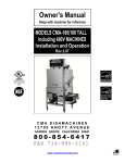
MODEL CMA-180VL
Installation and Operation
Manual
Rev 2.00A
CMA DISHMACHINES
12700 KNOTT AVENUE
GARDEN GROVE, CALIFORNIA 92841
800-854-6417
FAX 714-895-2141
www.cmadishmachines.com
Table of Contents
Model CMA-180VL
1.
SPECIFICATIONS................................................................................................. 4
1.1
2.
CMA-180VL .................................................................................................................................. 4
GETTING STARTED ............................................................................................ 6
2.1.
Introduction to CMA-180VL .......................................................................................................... 6
2.1.1.
Plumbing Chart ...................................................................................................................... 6
2.2. Receiving and Installation ................................................................................................................ 8
2.2.1. Electrical .................................................................................................................................... 8
2.2.2. Plumbing .................................................................................................................................... 8
2.2.3. CMA Supplied Nova Detergent and Rinse Dispenser (Optional) ............................................... 8
2.2.5. Water Tempering Kit (Optional) ..............................................................................................11
2.2.6. Installation Checklist ..................................................................................................................12
2.2.7. Machine Start-Up Procedures ...................................................................................................12
2.2.8. Electrical Requirements ..............................................................................................................14
3.
WIRING OPTIONS.............................................................................................. 15
4.
QUICK SERVICE GUIDE .................................................................................. 16
5.
INITIAL PARTS KIT P/N 1100.17 ..................................................................... 17
6.
AUTO-FILL SOLID STATE TIMER ................................................................ 18
7.
WIRE DIAGRAM CMA-180VL 240V ............................................................... 19
8.
WIRE DIAGRAM CMA-180VL 240V BOOSTER ONLY .............................. 20
9.
WIRE DIAGRAM CMA-180VL 480V ............................................................... 21
10.
WIRE DIAGRAM CMA-180VL 480V BOOSTER ONLY .............................. 22
MODEL CMA-180VL INSTALLATION & OPERATION Rev. 2.00
Page 3
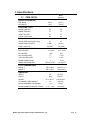
1. Specifications
1.1
Metric
Equivalent
CMA-180VL
WATER CONSUMPTION
PER RACK
.89 G
(3.37 L)
PER HOUR
52 G
(197 L)
WASH TIME-SEC
49
49
RINSE TIME-SEC
12
12
VENT FAN -SEC
41
41
TOTAL CYCLE-SEC
90
90
40
40
WASH TANK CAPACITY
8 GAL.
(30.3 L)
PUMP CAPACITY
52 GPM
(197 LPM)
OPERATING CYCLE
OPERATING CAPACITY
RACKS PER HOUR (NSF rated)
WATER REQUIREMENTS
COLD WATER
41°F-65F°
(5°C-18°C)
HOT WATER
140F°
60°C
HOT WATER INLET
½”
1.3cm
COLD WATER INLET
½”
1.3cm
DRAIN CONNECTION
2”
5.1cm
2
20 PSI ±5 PSI
1.41 kg/cm
WASH-°F
155°F-160°F
(68°C/71°C)
RINSE-°F
180°F-195°F
(82°C/90°C)
RINSE PRESSURE SET
CYCLE TEMPERATURES
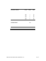
DIMENSIONS
DEPTH
29”
(76.7cm)
WIDTH
25 ½”
(65cm)
HEIGHT
85 ¼”-86 ¼”
(216-219)cm
STANDARD TABLE HEIGHT
34”
(86.3cm)
MAX CLEARANCE FOR DISHES
17 ½”
DRAIN CONNECTION (OFF FLOOR)
11 ½“ – 12½“
MODEL CMA-180VL INSTALLATION & OPERATION Rev. 2.00
(44cm)
(29-32cm)
Page 4
ELECTRICAL RATING
SHIPPING WEIGHT
MODEL CMA-180VL INSTALLATION & OPERATION Rev. 2.00
VOLTS
PHASE
AMPS
208
1
78
240
1
88
208
3
49
240
3
55
480
3
25
332#
Page 5
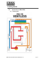
2. Getting Started
2.1.
Introduction to CMA-180VL
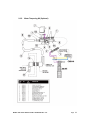
2.1.1. Plumbing Chart
MODEL CMA-180VL INSTALLATION & OPERATION Rev. 2.00
Page 6
The CMA-180VL is a hot water sanitizing, single rack, door-type dishmachine. It is a stand-alone
machine featuring a self-contained booster heater. The only external connections necessary are
power supply, water supplies, drainpipe, and chemical dispensers. The machine utilizes recirculated wash water and fresh water final rinse.
The machine is equipped with the built in Heat Recovery System which reduces significantly the
humidity in the dishwashing room. The Heat Recovery System uses the heat of the steam
generated during the wash cycles to warm up the in-feed water (41F -65F) before entering the
booster heater.
Operation of the CMA-180VL is automatic. When the door is opened and then closed, the wash
cycle begins automatically. To initially fill the machine daily, press auto fill rocker switch. The
machine is full when water begins to flow into the scrap trap. The wash tank heater will maintain
the wash water temperature at 155°F. The booster heater will produce a minimum of 180°F final
rinse water each cycle providing the incoming cold water supply is a minimum 41°F.
This manual is structured to provide a complete reference guide to the CMA-180VL. It is
presented in a manner that all users will be able to comprehend and use as an effective tool in
supporting the operation and maintenance of the dishmachine. The first section explains how the
machine is packaged and what to look for when receiving the machine.
Instructions are provided in the manual explaining how to unpack the machine and then install
and set up the machine for use. Requirements are given for plumbing, wiring, and space
considerations. These attributes of the machine are always taken into consideration by our welltrained sales representatives prior to the order being placed. In the manual, additional installation
guidance is given to ensure the machine can run at optimum conditions.
The Operation Section of the manual may be used for instruction and procedures when required.
We make this portion of the manual easy to understand so that all levels of operators may be
able to read and comprehend the operation of the machine. The function of the machine itself is
mostly automatic and takes little training to put into full operation. The Operation Section also
includes diagnostic considerations for the machine when problems occur.
Our mission is to provide our customers with the highest quality products and the highest
quality service, always delivering more than we promise and more than he or she expects.
We will strive to do business the way the customer wants to do business, on a mutually
profitable basis.
We are committed to providing the best machines and customer service in the food
industry and your feedback is welcome.
CMA warranties the workmanship of the machine.
Warning: the CMA-180 VL has a Heat Recovery (HR) system comprised of heat exchange coils
that can become restricted or clogged if the water supplied to the machine contains lime scale,
known as hard water conditions. The cold water supplied to the CMA-180 VL should be analyzed
and treated to maintain maximum 3 grains water hardness to prevent scaled conditions. First sign
of a problem will be restricted or zero rinse flow to the rinse arms.
Failure to provide soft water (3g or less), will void the machines warranty.
DISCLAIMER OF LIABILITY OF WARRANTY: CMA EXPRESSLY DISCLAIMS ANY AND ALL WARRANTIES, EXPRESS OR IMPLIED, RELATING TO THE INSTALLATION OF ANY AND ALL
CMA EQUIPMENT THAT IS INSTALLED BY CHEMICAL DEALERS, CONTRACTED SERVICERS OR THIRD PARTY SERVICERS TO CMA EQUIPMENT.
IF THE INSTALLATION
INSTRUCTIONS ARE NOT FOLLOWED EXACTLY (TO THE LETTER), OR, IF ANY PERSON OR COMPANY CONDUCTING THE INSTALLATION OF THE CMA EQUIPMENT, REVISE THE
INSTALLATION PROCEDURES OR ALTER THE INSTRUCTIONS IN ANY MANNER, THE CMA WARRANTY BECOMES VOID. IF, DUE TO THE IMPROPER INSTALLATION OF CMA
EQUIPMENT, THIS EQUIPMENT CEASES TO OPERATE PROPERLY OR AFFECTS OTHER PARTS OF THE CMA DISHWASHING EQUIPMENT, IN THAT THE OTHER PARTS BECOME
DEFECTIVE, THE CMA WARRANTY BECOMES VOID. CMA WILL NOT BE LIABLE OR RESPONSIBLE OR WARRANT CMA EQUIPMENT, DUE TO IMPROPER INSTALLATION OF ANY
CMA MODEL DISHWASHER.
MODEL CMA-180VL INSTALLATION & OPERATION Rev. 2.00
Page 7
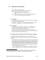
2.2.
Receiving and Installation
Step 1: Remove packaging material.
Step 2: Remove service manual from inside the wash tank.
Step 3: Adjust the feet. Set the machine in place.
Level the machine side – to – side and front – to –
back.
Step 4: It is recommended that a distance of at least eight inches (8”) be
between the table scrap sink and the dishmachine.
2.2.1. Electrical *
The control panel provides a 1” conduit connection point on the rear of the panel.
Refer to Section 3 for wiring options.
This machine is equipped to handle both single and three phase applications.
See Section 1: Specifications 1.1 for the proper electrical ratings.
2.2.2. Plumbing*
Minimum 140°F hot water supply ¾”. Minimum 45°F cold water supply ½”–
minimum 20 psi, 6 gpm flow rate and 60 gph recovery rate. Plumbing
connections located on the bottom of the machine.
The drain is a two inch (2”) pipe sleeve attached by “No-Hub” plumbing
connection at the bottom of the scrap trap. Account’s drain should be no higher
than 11” to allow the machine to drain properly.
2.2.3. CMA Supplied Nova Detergent and Rinse Dispenser * (Optional)
The NOVA Detergent and Rinse Dispenser has its own reference manual.
Familiarize yourself with the dispenser’s reference manual before proceeding with
installation.
1. The NOVA dispenser is pre-wired with a multi-conductor electrical cable that is to
be run through a conduit to the power block inside the control panel drawer. Use
a ½” watertight conduit meeting all local and national codes. A conduit fitting is
present on the bottom of the dispenser where the power cable exits. Use the
same conduit fitting in the back of the control box. The probe is also pre-wired
(see two violet wires routed from the control box to the probe location inside the
wash tank heater thermostat enclosure).
i.
Run an appropriate length of ½” conduit from your dispenser to the control
box where it will be secured. The conduit needs to be of sufficient length and
*
Electrical and plumbing connections must be made by qualified person who comply with all
available Federal, State, and Local Health, Electrical, Plumbing and Safety codes
MODEL CMA-180VL INSTALLATION & OPERATION Rev. 2.00
Page 8
flexibility to permit the machine to be moved for cleaning without having to
disconnect any wiring.
ii.
Run your dispenser wires through the conduit to the control box.
iii.
Run your probe wires to the control box.
iv.
With the machine’s power “OFF”, connect your detergent and rinse dispenser
wires to the red and blue terminals of the power block supplied inside the control
box. The table that follows lists the function of each conductor of the multiconductor electrical cable.
Wire Colors
Circuit Voltage
Function
Gray/Violet
200 VAC-249 VAC 50/60 Hz
Main AC Power
Brown
200 VAC-249 VAC 50/60 Hz
Main AC Power
Black
No Connection. Insulate this wire!
This wire is LIVE!
Yellow
24 VAC-240 VAC 50/60 Hz
Detergent Signal
White/Yellow
24 VAC-240 VAC 50/60 Hz
Detergent Signal
Violet
24 VAC-240 VAC 50/60 Hz
Rinse Signal
White/Violet
24 VAC-240 VAC 50/60 Hz
Rinse Signal
The individual conductors need to be connected as shown on the wire
diagram below. Probe wires are to be striped, crimped on barrel male and
female connectors provided, and connected to the pre-wired violet wires in
the control box.
2. Remove the plug from the mixing chamber located by the vacuum breaker on the
back of machine; and install the rinse injection fitting (supplied with your
dispenser).
3. A 7/8” detergent injection hole is provided in the back of the wash tank. Remove
the S.S. plug and install the detergent fitting (supplied with your dispenser).
MODEL CMA-180VL INSTALLATION & OPERATION Rev. 2.00
Page 9
4. A 7/8” chemical probe hole is provided in the front of the wash tank heater just
below hi limit switch. Insert the probe into the hole from inside the wash tank and
secure it with the probe retaining nut provided. Connect ring connectors to the
probe with nuts and star washers provided.
5. The final step of installing the CMA supplied Detergent and Rinse Dispenser is
programming it to your specific application. The reference manual supplied with
the dispenser shows you how to program it.
Keep in mind while reading the reference manual that the CMA-180VL
operates in “probe” mode. (This mode is selected by setting a value of “1” in
screen 21).
Screen 22 must be set to “1” (Door).
There are four user functions with this dispenser. Their operation is described in the
reference manual.
MODEL CMA-180VL INSTALLATION & OPERATION Rev. 2.00
Page 10
2.2.5.
Water Tempering Kit (Optional)
MODEL CMA-180VL INSTALLATION & OPERATION Rev. 2.00
Page 11
2.2.6. Installation Checklist
Dishmachine checked for concealed damage.
Hot water supply is 140° (60°C)
Cold water supply is 45° (7°C) min
Incoming water supply lines are ¾”.
Incoming water supply is 6 gpm minimum capable at 20 psi flow pressure.
Machine circuit breaker is properly sized.
Service voltage and phase type are correct to machine data plate.
High leg of voltage is connected to L2 (three-phase).
Dishmachine is properly ventilated.
Floor drain plumbing is installed with air gap. MUST MEET LOCAL CODES.
Dishmachine is properly grounded.
Dishmachine is properly leveled.
Dishrack guides are adjusted to level of dishtable.
Machine circuit breaker is labeled D/W
2.2.7. Machine Start-Up Procedures
1. Place the scrap baskets over the wash tanks.
2. Secure the wash & rinse arms and check the free-spin.
3. Open the control panel and select ‘normal” toggle switch position.
4. Adjust the rinse pressure to 20 PSI flow pressure using the regulator and the gauge
provided on machine.
a. Turn the power switch to the “Off” position.
b. Close doors and open the hand-operated fill valve until the water overflows into
the scrap trap.
c.
Turn the power switch to “on” position. SEE NOTE FOR BOOSTER HEATER
BELOW.
d. While holding “flush” toggle switch, to activate the water solenoid, adjust the
pressure regulator until the gauge reads 20 PSI. NOTE: Booster heater is filled
during this procedure.
5. Connect the detergent and rinse dispenser to the power block supplied & labeled inside
the control panel (208-220) volt.
6. Remove the plug from the mixing chamber and install the rinse injection fitting.
7. A 7/8” chemical probe hole is provided in the wash tank behind wash tank heater cover.
8. A 7/8” detergent fitting hole is provided in the wash tank behind the machine.
9. Check the machine operating temperatures. Adjust if necessary.
MODEL CMA-180VL INSTALLATION & OPERATION Rev. 2.00
Page 12
a. After the machine has warmed up for five to ten minutes (5 – 10 min.), observe
the wash and rinse temperatures. The wash temperature must be 155°F
minimum. The rinse temperature must be 180°F minimum. If necessary, adjust
the temperatures by removing the panel in front of the respective heater and
turning the adjustment stem clockwise to increase.
NOTE: Rinse water temperature must be observed during the rinse cycle.
10. Check all water and drain fittings for leaks.
11. Install the wall chart and instruct the machine operator on the proper cleaning and
operation of the CMA-180VL.
Caution: Booster Heater
Booster heater is shipped on the dishmachine empty to prevent freezing. When the
machine is powered up for the first time, the booster heater must be filled immediately to
prevent damage to the heating element. See Section 2.2.7 (4d.)
To prevent booster heater element damage, CMA has removed a wire from the high limit
switch. When initially filling of a newly installed dishmachine, you must fill the booster
tank prior to connecting the removed wire. When water is observed entering the wash tank
this indicates the booster tank is full and removed wire can be connected. Failure to follow
these important instructions will destroy the heating element because of dry -firing.
MODEL CMA-180VL INSTALLATION & OPERATION Rev. 2.00
Page 13
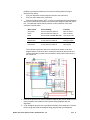
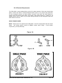
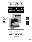
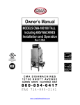
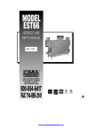
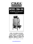
2.2.8. Electrical Requirements
The CMA-180VL comes standard factory, wired for 3-phase operation. Check the electrical data
plate to confirm this. Refer to “Electrical Requirements” Figure 1-A, for proper wiring instruction
for both rectangular booster and wash heaters conversion. Also check the wiring diagram to
properly wire the terminal power block, tank heater, and booster heater for 1 phase (or 1B
diagram below). Refer to Figure 1-B, for proper wiring instruction for both triangular booster and
wash heaters conversion.
SINGLE PHASE POWER
NOTE: 80amp service is required when CMA-180VL is wired for single-phase with the booster
heater. See “Wiring options” section for DUAL 1-phase power supply. Circuit breaker
requirement (1) 50 amp & 30 amp
Figure 1-A
Figure 1-B
MODEL CMA-180VL INSTALLATION & OPERATION Rev. 2.00
Page 14
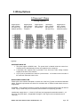
3. Wiring Options
3-Phase and 1 Phase
Wiring Options
Single-Source
220V 3-Phase
(20 amp/12 g*)
(Without booster)
Single-Source
220V 3-Phase
(50 amp/8 g*)
Standard
Single-Source
220V 1-Phase
(80 amp/4 g*)
Two-Source
220V 1-Phase
(50 amp/8 g*)
(30 amp/10 g*)
Single-Source
220V 1-Phase
(30 amp/10 G*)
(Without booster)
*g=gauge
DISPENSER HOOK-UP
1. The power signal is 208/230 volts. The power block is labeled inside the control box.
Conduit holes for both detergent & rinse are supplied on the control box.
2. A threaded (1/8”) injection point is provided on the final rinse Teflon mixing chamber
located off the back of the machine.
3. A (7/8”) hole is provided in the tank for a probe access. It is located on the front side of
the wash tank inside the heater cover.
MAIN POWER CONNECTION
Please refer to the machine data plate or choose one of the five (5) power connections illustrated
above. Electrical requirements are shown for machines with or without booster heater, three or
single phase.
WARNING: Insure that the machine is properly grounded and complies with all local and national
codes. Injury or death may occur from shock, if the machine is not properly grounded.
Install power supply wires, L1, L2 and L3 (3-Phase) to the appropriate terminals marked L1, L2,
and L3 on the power block. (If applicable, the high or “wild” leg must be connected to the L2
Terminal.)
MODEL CMA-180VL INSTALLATION & OPERATION Rev. 2.00
Page 15
4. Quick service guide
MODEL: CMA 180 VL HIGH TEMP
SOLUTION
Check wire connections inside control box
TECHNICAL ISSUE
Door magnetic reed switch problem
CAUSE
Faulty magnetic reed switch
Door mechanical switch problem
Switch alignment issue
Align switch
Switch button broke
Replace switch,
Delimer switch is in OFF position
Flip to NORMAL position
Loose wire connections
Check and crimp connectors
Faulty # 3 micro switch in cam timer
Replace micro switch,
Faulty contactor
Replace contactor,
Faulty wash pump motor
Replace wash pump motor,
Faulty # 3 micro switch in cam timer
Replace micro switch,
Delimer switch is in DELIME position
Flip to NORMAL position
Faulty contactor
Replace contactor,
Booster heater thermostat not properly set
Adjust thermostat
Contact factory for new retrofit, corner straight
Pump motor not running
Pump motor runs continuous
Final rinse water below 180 degree F
Wash tank heater is not operational
Incoming main water temperature below 140 F Raise water temperature to 140 F
Tripped or faulty high limit switch
Reset or replace high limit switch,
Faulty contactor
Replace contactor,
Faulty booster heater element
Replace heating element,
Scaled heating element
Thermostat is not properly adjusted
De- scale heating element
Adjust thermostat
Loose lead connection
Tripped or faulty high limit switch
Check connectors and secure
Reset or replace high limit switch,
Faulty float switch
Replace float switch,
Faulty contactor
Replace contactor,
Faulty heating element
Replace heating element,
Water regulator not adjusted properly
Adjust regulator to 18-20 PSI
Clogged final rinse spray jets
Low water pressure at the final rinse Missing final rinse spray end cap
Water solenoid leaks
Low incoming water pressure from building
Scaled or dirty solenoid valve
Increase pressure
Faulty solenoid valve diaphragm
Thermostat not properly set
Replace diaphragm,
Adjust thermostat
Wash water temperature too low/high Scaled heating element
Machine does not operate when the
door is closed
Clean jets
Replace end cap,
Clean valve
Clean scale, delime machine
Faulty temperature gauge
Position or proper operation of door switch
Replace gauge,
Adjust or replace door switch,
Delimer switch is on OFF position
Faulty 1st micro switch in cam timer
Flip to NORMAL position
Replace micro switch,
Check cam timer motor
Replace timer if needed,
Check ice cube relay
Replace if faulty,
Replace contactor,
Faulty wash pump contactor
MODEL CMA-180VL INSTALLATION & OPERATION Rev. 2.00
Page 16
5. INITIAL PARTS KIT P/N 1100.17
P/N
00121.18
00200.10
00206.00
00302.19
00304.17
00304.19
00308.17
00308.50
00363.00
00404.85
00405.00
00411.00
00421.78
00421.90
00475.00
00501.17
00562.00
00602.00
00631.05
00706.00
00735.00
00738.15
03202.00
03202.00
03408.55
13003.17
13003.50
13304.55
13415.00
13417.47
13422.71
13417.85
13463.10
13605.00
15518.00
17523.51
DESCRIPTION
CMA-180VL Drain Stopper O Ring
Pump Assy 110/220V 60 Hz (Open)
Pump Seal Kit
CMA-180VL Buna Gasket (#302.17)
CMA-180VL Wash Spray Arm
CMA-180VL Rinse Arm W/Bearing
CMA-180VL Rinse Arm SS End Plug
Spray Arm End Plug SS
Spray Base Lock Pin
Contactor 208.240V 20AMP
Start/Fill Switch Toggle
Micro Switch
CMA-180VL Illuminated Plug
CMA-180VL Power Switch
Toggle Switch DPDT 15 AMP/Delimer
Timer Motor Assy 60 Sec. 220V/60Hz
Roller Door Switch
Door Spring
Ice Cube Relay 220V
¾ Water Solenoid Repair Kit JE
¾ Vac Breaker Rep Kit Watts
¾ Solenoid Coil JE 220V
Thermometer CMA-180VL “Wash”
Thermometer CMA-180VL “Rinse”
Counter (Face Mount Sm) 220/50
Contactor 60 AMP 3 Pole
Contactor 30 AMP
SS Final Rinse Spray Jet – HT
EGO Thermostat Retrofit Kit Rinse
CMA-180VL Booster Heater Gasket
Immersion Heater 12 Kw 3PH/1PH, 240V
Thermostat Heater CMA-44/CMA-180 Wash
Liquid Level Switch SS – CMA-44
Pressure Gauge
Immersion Heater 6 Kw 3hp/1ph, 240V
Hi Limit Switch 250 deg
NO. REQ’D
1
1
1
1
1
1
1
1
1
1
1
1
1
1
1
1
1
1
1
1
1
1
1
1
1
1
1
1
1
1
1
1
1
1
1
1
NOTE: CMA recommend that this Model CMA-180VL initial parts kit be
kept on hand, as a back up supply, in the event your machine should
require emergency service. All the parts included in this kit are
unique to the CMA-180VL dishmachine, and are essential to the
“quality” operation and customer service to the CMA-180VL unit.
MODEL CMA-180VL INSTALLATION & OPERATION Rev. 2.00
Page 17
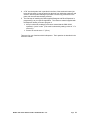
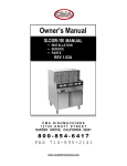
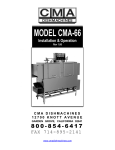
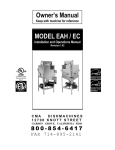
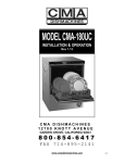
6. Auto-Fill Solid State Timer
Pre-selected delay period can be adjusted by
turning dip switches on for proper time setting.
Removal of input power will reset the control.
AUTO-FILL
SWITCH
violet
violet
L2
L1
WASH PUMP
CONTACTOR
6
T2
WATER
SOLENOID
VALVE
T1
1
2
3
red
blue
MODEL CMA-180VL INSTALLATION & OPERATION Rev. 2.00
orange
blue
Page 18
GND
L3
L2
L1
DETERGENT
RINSE
GROUND
DOOR
SAFETY
SWITCH
{
{
PUMP
MOTOR
1
6
2
3
WASH TANK
HEATER
6kW
ADJ.
THERMOSTAT
FLOAT
SWITCH
8
T1
HI LIMIT
SWITCH
6
L1
TIMER FOR
AUTO-FILL
START
C
T2
RINSE
RINSE
SOLENOID
VALVE
4
5
FAN
MOTOR
2
L2
T3
OFF
DELIME
NORMAL
OPTIONAL
AUTO-FILL
VALVE
8
NC
NO
L3
T1
T2
T3
T1
T2
COUNTER
CYCLE
LIGHT
06/04/2012
7
L1
L2
L3
L1
L2
OPTIONAL
AUTO-FILL
SWITCH
4
2
NC
1
POWER
SWITCH
WASH PUMP
CONTACTOR
HEATER
CONTACTOR
MODEL CMA-180VL INSTALLATION & OPERATION Rev. 2.00
1
3
BOOSTER
HEATER
CONTACTOR
6
C
6
NO
5
3
5
7
2
3
8
7
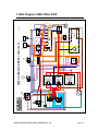
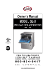
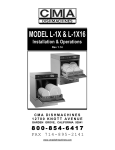
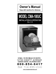
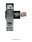
WIRE DIAGRAM FOR MODEL: CMA-180 VL:
7. Wire Diagram CMA-180VL 240V
Page 19
GND
L3
L2
L1
DETERGENT
{
RINSE SIGNAL {
PUMP
MOTOR
L1
L2
L3
L1
L2
L3
L1
HEATER
CONTACTOR
BOOSTER
HEATER
CONTACTOR
T1
T2
T3
T1
T2
T3
T1
T2
3
ADJ.
THERMOSTAT
HI LIMIT
SWITCH
2
C
5
BOOSTER
HEATER
12kW
L-
2
TOP
L-
1
3
L-
1-PHASE
WASH TANK
HEATER
6kW
L1
L2
TOP
3-PHASE
L3
L-
2
TOP
1-PHASE
6 kW HEATER WIRING OPTIONS
CONDENSER
FLUSH
VALVE
L-
L-
2
L-
TOP
3-PHASE
8
6
4
7
2
NC
NO
1
3
12kW HEATER WIRING OPTIONS
1
6
CONDENSER FLUSH
2
1
L2
L-
L-
GROUND
2
1
MODEL CMA-180VL INSTALLATION & OPERATION Rev. 2.00
L-
L-
WASH PUMP
CONTACTOR
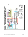
BOOSTER HEATER AND CONDENSER FLUSH
WIRE DIAGRAM FOR MODEL: CMA-180VL
8. Wire Diagram CMA-180VL 240V Booster Only
1
1
Page 20
GND
L3
L2
L1
DETERGENT
RINSE
GROUND
DOOR
SAFETY
SWITCH
{
{
7
PUMP
MOTOR
L3
1
6
2
3
WASH TANK
HEATER
6kW
6
ADJ.
THERMOSTAT
FLOAT
SWITCH
START
8
T1
HI LIMIT
SWITCH
RINSE
6
L1
TIMER FOR
AUTO-FILL
C
T2
T3
RINSE
SOLENOID
VALVE
4
5
FAN
MOTOR
2
L2
T1
T2
T3
T1
OFF
DELIME
NORMAL
OPTIONAL
AUTO-FILL
VALVE
02/05/2013
8
NC
NO
L3
T3
T2
COUNTER
CYCLE
LIGHT
7
L1
L2
L3
L1
L2
OPTIONAL
AUTO-FILL
SWITCH
2
NC
1
POWER
SWITCH
HEATER
CONTACTOR
HEATER
CONTACTOR
MODEL CMA-180VL INSTALLATION & OPERATION Rev. 2.00
1
3
BOOSTER
HEATER
CONTACTOR
4
NO
6
3
5
3
C
2
5
8
7
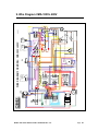
WIRE DIAGRAM FOR MODEL: CMA-180VL 480V:
9. Wire Diagram CMA-180VL 480V
* AMP FUSE
SLOW BLOW
(x2)
1.25 AMP FUSE
SLOW BLOW
(x2)
Page 21
GND
L3
L2
L1
DETERGENT
{
PUMP
MOTOR
L1
L2
L3
L1
L2
L3
L1
L2
T1
T2
T3
T1
T2
T1
T2
T3
5
1
L-
2
L-
TOP
3-PHASE
3
L-
8
6
BOOSTER
HEATER
1
L-
2
L-
TOP
1-PHASE
L1
L2
TOP
3-PHASE
L3
L1
L2
TOP
1-PHASE
6 kW HEATER WIRING OPTIONS
ADJ.
THERMOSTAT
12kW
C
6kW
7
CONDENSER
FLUSH
VALVE
WASH TANK
HEATER
3
4
2
HI LIMIT
SWITCH
2
NC
NO
1
3
12kW HEATER WIRING OPTIONS
1
6
1
RINSE SIGNAL {
L-
WASH PUMP
CONTACTOR
HEATER
CONTACTOR
BOOSTER
HEATER
CONTACTOR
CONDENSER FLUSH
2
1
T3
L-
L-
L3
2
GROUND
L-
MODEL CMA-180VL INSTALLATION & OPERATION Rev. 2.00
* AMP FUSE
SLOW BLOW
(x2)
1.25 AMP FUSE
SLOW BLOW
(x2)
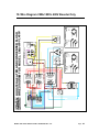
BOOSTER HEATER AND CONDENSER FLUSH
WIRE DIAGRAM FOR MODEL: CMA-180VL 480V
10. Wire Diagram CMA-180VL 480V Booster Only
Page 22