1
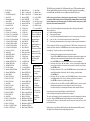
Specifications
Midi Pro - midi to dmx RGB Controller
Size
(W) 250mm x (D) 170mm x (H) 70mm
Weight
1.45Kg
Power supply
220-240Vac adaptor to 9volt DC on controller
Output
DMX 512 protocol 64 channels
Signal Input
Opto isolated midi standard
Optional control
2 x Momentary Pedal ¼” mono jack connections
Midi Channels
16
Patterns
99 - includes floods, fades & chases
Dimming Levels
10
Lighting Channels - controlled by this unit are Red, Green & Blue
Limited standalone functionality (non midi controlled)
Easy Pattern/Chase/Dimming changing
The pattern programming of this unit is very simple.
Using the program change commands from your midi source simply send the required
pattern number as a MIDI Program Change number.
Pattern descriptions
The list of the 99 pattern/flood locations indicates what is available using a particular
program change number. If you lose this list check our website for info www.ryger.co.uk
Copyright Ryger UK 2013 ver0413
Made in England
www.ryger.co.uk
Ryger UK Ltd.
Midi Pro
99 pattern Pre-programmed
MIDI to DMX
RGB LED Parcan Controller
User Manual
RGB Parcan Profiles for Midi Pro
Description
Fixture Name
The Ryger Midi Pro is an easy to use multi-function midi to dmx light controller. Operated from any
midi source using the Program Change commands.
Fully controlled using the midi input this controller is ideal for Bands, DJ’s & fixed installations or any
situation utilizing midi to control RGB LED parcans, battens or panels
(battens & panels illuminate as a single colour unit).
The Midi Pro features 99 chase sequenced patterns inc various floods & fades, 4 methods of speed
control - inc Midi Clock ‘Tick’& ‘Note on’ detection, output dimming & blackout.
It is designed to operate DMX enabled RED, GREEN, BLUE static LED fixtures, Parcans etc.
Minimal DMX knowledge is required by the user. Some midi knowledge is ideally required but not
essential to be able to operate this unit.
The Midi Pro also has a limited standalone capability for backup use in the event of a midi signal
failure or if a quick setup without using midi control is required. There are also two ¼” mono jack
sockets for connecting any momentary foot pedals (pedals supplied optionally) to gain further control.
IMPORTANT
It is important that the set up instructions are fully read in this booklet as they will guide you through
the various processes to connect your Ryger Midi Pro controller to your LED products.
Connections
Mains Input:
Is via the 9v 500mA DC transformer supplied with this unit. The power socket is located on the R/H
side.
Outputs:
Outputs are made via DMX 512 standard 3 Pin XLR socket. Pin1 = shield, Pin2 = cold -, Pin3 = hot +
Inputs
Standard MIDI in connection is provided – there are no thru connections; midi in is wired to a 5 pin
180º DIN socket on the front panel as follows :MIDI in connector details
Midi In
1 N/C
2 Screen
3 N/C
4 MIDI +
5 MIDI -
Acme CF-805 Color Bar (4ch mode)
Acme Slimline LED Parcan (Mode2)
Eurolite LED T-36 Parcan
Eurolite LED Par 56
Eurolite LED Par 64
Multiform PS020A DMX Power Supply
JB Systems LED Spot
JB Systems LED Wash
LEDJ RGB 252
LEDJ Alu Par 64
LEDJ Alu Tri Par 64
LEDJ Par 56 Parcan
LEDJ Par 64 Parcan
LEDJ Spectra Batten 76
LEDJ Spectra Batten 76A
QTX Slimline Parcans
i-Solutions Stage Wash (3ch - no white)
i-Solutions Color Bar 12TC (3ch mode)
Showtec RGB LED Spot
ACME LED Color Spot
Equinox Maxibar (3ch mode)
Equinox Megabar (3ch mode)
LEDJ Octobloc (3ch mode)
LEDJ Stage Par 64 3w (3 ch mode)
LEDJ Stage Par 64 (3ch mode)
LEDJ Stratos Spot
LEDJ Stratos Wash
LEDJ Spectra Batten - led display 03CH (3ch mode)
ADJ Punch LED Pro (3ch mode)
ADJ Mega Tri Bar (3ch mode)
ADJ Mega Panel (3ch mode)
ADJ Mega Bar (3ch mode)
ADJ Mega Bar Pro (3ch mode)
KAM LED 800 (3ch mode)
Kam LED 800S (3ch mode)
Kam LED Quad Bar mk1
Showtec Par 56 Short LED
Showtec Par 64 Short LED
Showtec Par 36 Pinspot LED
Showtec LED RGB Par 64 (3ch mode)
Showtec Design Par 18 (arc1 mode)
Chauvet Colorado 1 Tri Tour (Tour Mode)
Lanta Fireball PAR 64
LEDJ Spectra PAR 88
LEDJ Spectra Flood 87
LEDJ Omni Tri
LEDJ Color Burst
LEDJ Xterior Wash
KAM LED Par 36
Kam LED Par 56
Kam LED Par 64m
LEDJ Pixel Bar (6ch mode)
LEDJ Spectra Batten 75
LEDJ Spectra Batten 75A
LEDJ Pro RGB Spectra Batten 1.0M
ADJ Par 56 LED Plus
ADJ Par 64 LED Plus
ADJ P56P Parcan
ADJ Par 36 Parcan
Red
Green
Blue
Dimmer
DMXLevel
(dimmer)
255
255
255
255
255
255
255
255
255
255
255
255
255
255
255
255
Parcan
Profile
"bb" 0
1
1
1
1
1
1
1
1
1
1
1
1
1
1
1
1
2
2
2
2
2
2
2
2
2
2
2
2
2
2
2
2
3
3
3
3
3
3
3
3
3
3
3
3
3
3
3
3
4
4
4
4
4
4
4
4
4
4
4
4
4
4
4
4
1
1
1
1
1
1
1
1
1
1
1
1
1
1
1
1
1
1
1
1
1
1
1
1
1
2
2
2
2
2
2
2
2
2
2
2
2
2
2
2
2
2
2
2
2
2
2
2
2
2
3
3
3
3
3
3
3
3
3
3
3
3
3
3
3
3
3
3
3
3
3
3
3
3
3
2
2
2
2
2
2
2
2
2
2
3
3
3
3
3
3
3
3
3
3
4
4
4
4
4
4
4
4
4
4
1
1
1
1
1
1
1
1
1
1
255
255
255
255
255
255
255
255
255
255
4
4
4
4
5
5
5
5
6
6
6
6
2
2
2
2
255
255
255
255
"bb" 3
1
1
1
1
2
2
2
2
3
3
3
3
6
6
6
6
63
63
63
63
"bb" 4
"bb" 1
"bb" 2
Setup Information
KAM LED Power Can 24W (3ch or 7ch mode)
1
1
1
2
2
2
3
3
3
7
7
7
255
255
255
"bb" 5
KAM LED Power Can 36W (3ch or 7ch mode)
KAM LED Power Can 54W (3ch or 7ch mode)
Read this section fully - Minimal DMX knowledge is required by the user.
8 fixtures can be controlled separately with this unit.
All fixtures you use should ideally be of the same manufacture type or must operate on the same
RGB channels – check user manuals for this information if you are mixing different fixture types
(not advised without some DMX knowledge).
ZOOM Slimline Par 64 LED (dip 10 on for DMX)
1
2
3
4
189
"bb" 6
Batmink Par 56
2
2
2
3
3
3
4
4
4
3
4
5
2
255
"bb" 8
2
3
4
1
210
"bb" 9
Starville Par56
Pulse Par 56 Eco
Chavet Colour Strip (3 ch mode)
"bb" 7
1.
2.
3.
4.
5.
6.
7.
8.
9.
10.
11.
12.
13.
14.
15.
16.
17.
18.
19.
20.
21.
22.
23.
24.
25.
26.
27.
28.
29.
30.
31.
32.
33.
34.
35.
36.
37.
38.
39.
40.
41.
42.
43.
44.
45.
R,G,B.Y Flood
All on RED
1234 GREEN dim to Full
All on BLUE
Random Singles (4ch)
All on GREEN
Colour Fade ALL ON
All on MAGENTA
Blackout – ALL OFF
Random Multi
4+5 Static W. 6 x Colour FA
4+5 Static W. 6 x Colour FLash
4+5 Static W. G+B Swap FA
4+5 Static W. G+B Swap FLash
4+5 Static W. M+B Swap FA
4+5 Static W. M+B Swap FL
4+5 Static W. R+B Swap FA
4+5 Static W. R+B Swap FL
Green Wave ALL ON
Strobe BLUE
Alt MAGENTA FLash
Alt MAGENTA Dim
Alt FAde RED Dim
Alt FAde MAGENTA Dim
Alt FAde GREEN Dim
Alt FAde BLUE Dim
FAde all 8 Colours
Alternate MAGENTA FLash
Alternate GREEN FLash
Strobe GREEN
FAde 2+2 R/M (4ch)
FAde 2+2 R/G (4ch)
FAde 2+2 R/B (4ch)
All on PINK
FAde 2+2 B/Y (4ch)
FAde 1234 RED
FAde 1234 MAGENTA
FAde 1234 GREEN
FAde 1234 BLUE
Strobe RED
FAde 1+1 YELLOW(4ch)
All on YELLOW
FAde 1+1 RED (4ch)
FAde 1+1 MAGENTA(4ch)
FAde 1+1 GREEN (4ch)
46.
47.
48.
49.
50.
51.
52.
53.
54.
55.
56.
57.
58.
59.
60.
61.
62.
63.
64.
65.
66.
67.
68.
69.
70.
71.
72.
73.
74.
75.
76.
77.
78.
79.
80.
81.
82.
83.
84.
85.
86.
87.
88.
89.
90.
FAde CYAN (4ch)
91. Mixed Static
FAde 1+1 Colours (4ch)
92. Blackout Chase
FAde 1+1 BLUE (4ch)
93. Blackout Chase M
Alternate RED FL
94. Centre Fill RED
Strobe WHITE FL
95. Soft White
Alternate BLUE FL
96. Fade Chase Colours
Alternate BLUE Dim
97. Grow RED BLUE
4 Chase Colours
98. GREEN Cascade
2+2 R/M (4ch)
99. Letterwrite BLUE.
2+2 R/G (4ch)
These are the patterns
2+2 R/B (4ch)
That are available for
2+2 G/M (4ch)
2+2 G/B (4ch)
selection using midi
2+2 Colours (4ch)
program changes –
Strobe WRGB
Simply send the
All Colour Fade
pattern number as a
All on CYAN
Program Change.
All on ORANGE
Also use one of these
Delay Chase RED
numbers in the ‘EE’
White Chase Colours
section of the config
Count RGB reverse
setup to assign it to
2 Chase Colours
one of the pedal
4+4 BLUE (8ch)
sockets.
4+4 GREEN (8ch)
4+4 RED (8ch)
4+4 RGB (8ch)
You can alter
4+4 Swap R/B (8ch)
the preset speed
Bounce BLUE (8ch)
at any time by
Bounce GREEN (8ch)
sending
Bounce RED (8ch)
Program change
Bounce MAGENTA (8ch)
number 101.
Alternate BLUE (4ch)
Whilst this is
Alternate GREEN (4ch)
activated
Alternate RED (4ch)
FAde 8 - Colours
sending any
FAde 4+4 BLUE (8ch)
number between
FAde 4+4 GREEN (8ch)
104 (slow) to
FAde 4+4 Swap R/B (8ch)
113 (fast) will
FAde 8-1 GREEN (8ch)
change the
FAde 8-1 RED (8ch)
speed of the
FAde Bounce BLUE Dim
chase.
FAde Bounce GREEN Dim
FAde Bounce MAGENTA Dim
FAde Bounce RED Dim
FAde Cascade GREEN Dim
The Midi Pro can be configured for 10 different profile types of LED parcans/bars/panels.
The list supplied will help you choose which type is required and give the corresponding
code number that you will need to use to configure the controller for first use.
Profile codes for various fixtures are listed on the last page of the manual – If yours is not listed
just match the DMX information for the RGB channels and a dimmer/Shutter channel (if used)
with the information in your fixture user manual. The Midi Pro should be able operate any RGB
fixture that uses less than 8 channels of DMX.
There are 5 levels of user configuration that need setting on first use. Including 2 midi channels.
These are displayed as –
‘AA’ = Main controlling midi channel
‘bb’ = Parcan type profile number
‘CC’ = ‘Note On’ detection midi channel (this samples a ‘note on’ for setting a step speed to chases)
‘dd’ = ‘Note On’ Value – refer to the table of notes and octaves to obtain this value
‘EE’ = The favourite pattern number that you wish to assign to a pedal connection for manual access
To first configure the Midi Pro you need to hold down the CONFIG button & then power up the
controller, then release the button. The ENTER button stores the chosen setting and advances to the
next config stage. To make your choices you need to do the following 1.
2.
3.
4.
5.
The display will now alternate between showing ‘AA’ and a number.
Using the UP and DOWN Select buttons cycle through the options until the number in the
display matches the required main midi channel that you will use to control the Midi Pro.
Press the ENTER button to store your setting and move on to the next config item.
The display will now show ‘bb’ and a number - as above cycle through the numbers and
insert your parcan profile code as required, use the parcan list to identify your profile type.
Press ENTER as before.
The display will now show ‘CC’ use the UP & DOWN buttons & select the number for the
second midi channel that will be used for ‘Note On’ sensing ie: percussion channel.
Press ENTER again
The display will now show ‘dd’ use the UP & DOWN buttons & select the required
corresponding number for the ‘Note On’ value that you will detect ie: kick drum etc.
Press ENTER to save & move to the final stage of config.
The display will now show ‘EE’ use the UP & DOWN buttons & select the required
favourite pattern number that you wish to assign to the pedal if you are using one.
Press Enter to finally store your settings into the memory and the controller will reboot.
On powering up the chosen settings will display in rotation & flash briefly.
It will now remember this setting until such times as the user changes it.
This can be easily changed at any time by repeating the above procedure & changing only the item that
you need to. Then press ENTER repeatedly until the controller saves and exits the config mode.
Providing that all 8 fixtures use the same profile they will then operate correctly and access all 99
patterns within the unit.
During the power up cycle the Ryger Midi Pro will ignore any midi commands until fully booted up.
The display will cycle through the saved settings during this procedure.
Controlling Patterns
Midi Pro - FRONT PANEL INFORMATION
For simplicity of control all actions are performed using midi Program Change Numbers.
Send the number to the Ryger Midi Pro controller and it will carry out the required alterations to the
patterns. This is used to effect any pattern selections, dimming, speed and animation type. The table
below shows the Program changes and their effect on the Midi Pro controller. For advanced midi users
the true midi data values are also listed.
Ignore these two columns in normal use
Midi Program
Change Number
1-99
100
101
102
103
104-113
114-123
124
Description
Pattern number
Default Pattern
speed
Manually control
Pattern speed
Midi ‘clock tick’
Pattern step
control
‘note on’ clock
Pattern step
control
pattern speeds:104=slow
to
113=fast
(only works when
manual speed 101
mode is selected)
Dimming control
114= approx 10%
115= approx 20%
Etc
Etc
123 = 100%
midi ‘clock tick‘
Actual Midi
data value
0-98
99
Internal pattern
number
0-98
n/a
100
n/a
101
n/a
102
n/a
103-112
n/a
LED indicates pattern
animation method being used
Default Speed (off)
Manually adjust speed (on)
Use Midi clock speed (blinking)
LED indicates animation type
when using midi clock tick.
Single clock ‘Tick’ (off)
‘Note on’ detection (on)
LED blinks when each pattern
step is implemented
CONFIG Button
UP Button
ENTER Button
DOWN Button
LED indicates
when in
Optional wall fixing kit available
from Ryger
LED blinks when incoming
Midi signal present
Standalone (on) or Midi
control (off) mode
Fixture Codes
The separate list of profile codes is a small selection of the most common fixture types.
For a detailed fixture list visit www.ryger.co.uk
0, 1, 2, 3, 4, 5, 6, 7, 8, 9 are the options available. If you are unsure you can simply retry every profile
in turn with your fixture connected, restarting the controller each time.
113-122
n/a
123
n/a
Ignore these two columns in normal use
Chase Speed & Pattern Selection
Selecting a pattern number between 1-99 will start that pattern running.
The default speed will run if you send Program Change 100 at any time.
To alter the speed send Program change 101 (the animation indicator LED will be ON), you then need
to send the required speed number between 104 and 113. Anytime whilst in this mode resending
between 104 and 113 will change the pattern chase speed.
When a manual speed has been set this will effect any pattern selections from that point on until a new
speed number is sent to the Midi Pro.
To work out an unlisted fixture refer to your fixture manual to identify the RGB channels & also
whether a Dimmer/Shutter need to be activated – ignore any strobe/macro channels and then match it
to the info on the profile sheet.
If you correctly identify an unlisted fixture to a profile please email the details to [email protected]
so that it can be added to the profile list.
If your fixture requires a new unidentified profile contact Ryger.
Linking fixtures together
You will need to link your fixtures and the controller together in a “daisy chain” from one fixture to
another using standard 3 pin XLR cables. Then after setting the dip switches or starting address they
will need plugging into their power source.
Instructions on the following page explain setting the address.
If you wish to use more than 8 fixtures you will need to duplicate the address settings on the extra
fixtures, these will then operate in tandem with the first 8 fixtures.
Some manufactures reverse the hot and cold pins 2 & 3 on XLR connections, if this is the case with
yours you will need to make a reversing lead up with one end having wires to pins 2 & 3 swapped over
DMX VALUES AND SETTINGS
In order to gain the most from the Ryger Midi Pro all of the fixtures have to be assigned their own
DMX settings. This will either be with dip switches or a digital setting on your fixtures.
Most of the LED parcans that are on the market currently run on 4 or 5 DMX channels.
A channel for red, blue, green and occasionally one for the master dimmer & presets.
But the FL-P1 runs all fixtures as if using 8 channels of DMX to incorporate the par-bars & panels
and such like that use more channels. So the address settings are always working from 8 channels.
Below is a guide on how to set your fixtures starting address or dip switches.
= Dip On
DIGITAL
6
7
8
001
Fixture 2
1 2 3
4
5
6
7
8
009
Fixture 3
1 2 3
Fixture 4
1 2 3
Fixture 5
1 2 3
4
4
4
5
5
5
6
6
6
To get a very accurate pattern chase use this method of speed control.
Send Program Change number 102 and activate this mode of animation
(Animation LED will blink – Clock mode LED will be off)
At any point that a step in the pattern is required send Program Change number 124 and the pattern
chase will advance by one step.
Midi ‘Note On’ Pattern Stepping (Program Change 103)
= Dip Off
DIPS SETTINGS
Fixture 1
1 2 3 4 5
Midi ‘Clock Tick’ Pattern Stepping (Program Change 102 then 124 to trigger step)
7
7
7
To obtain an auto sensing pattern advance the Midi Pro controller can monitor a second midi channel
that you selected in the config setup’CC’ along with the note selection ‘dd’ - this can be a note that is
used for a drum or other instrument associated with the beat of the song. Every time the Midi Pro
controller detects this note as ON it will advance the pattern by one step. See the note and octave chart
on page 5 to obtain the number that you require.
This is the easiest way to track the tempo of a song. It would only require setting at the start of a
backing track etc. If all backing tracks used the same note for the beat the Midi Pro controller would
automatically adjust the lighting tempo to suit each song.
To set this method of control send Program Change 103
(Animation LED will blink – Clock mode LED will be on)
Dimming
8
017
Dimming operates in the same way as manual speed control. Sending a Program Change number
between 114 and 123 will alter the brightness of the LED parcans. This level will remain active across
any pattern selections until you change it.
025
Foot Pedal Control (optional item)
8
8
Fixture 6
1 2 3
4
5
6
7
8
Fixture 7
1 2 3
4
5
6
7
8
Fixture 8
1 2 3
4
5
6
7
8
033
041
049
There are two ¼” mono jack sockets on the side of the Midi Pro these are for the connection of a
normal MOMENTARY non-latching footswitch. These will actuate the function upon the release of
the button/pedal after it has been depressed. To revert back to normal pattern chase etc press the
appropriate pedal again. The Midi Pro will return to the correct position in the pattern sequence.
One socket activates/deactivates a Blackout of the Parcans. When this pedal is activated ‘- -‘ appears
in the display. This pedal has the same effect in midi mode or standalone mode.
The other socket has two functions depending on the operation mode of the Midi Pro If used in midi mode this pedal will operate a favourite pattern that was preset (‘EE’) during the config
setup. When this pedal is activated ‘EE’ will appear in the display.
If used in standalone mode this pedal will advance through the 9 available patterns each time it is
pressed and released. After pattern 9 it will return to pattern 1 on the next press & release of the pedal.
Standalone mode (Not midi controlled) – Limited use mode for backup & quick setup
057
To enter standalone mode hold down the UP button whilst powering up the unit. Patterns 1 to 9 are
available using the UP and DOWN buttons. There are no speed or dimming adjustments in standalone
mode – The Ryger Midi Pro is primarily a midi controlled unit & this feature is designed to offer
some functional lighting in the event of the midi source failing.
This mode is really useful if you want to ‘step’ the lights to a particular midi note e.g. base drum
(midi note value for bass drum 2 is 35 and bass drum 1 is 36) .
Advanced Midi User information
The controller uses midi program change commands to control the various functions.
Midi program change command consists of two bytes:- status byte followed by data byte
Status byte = 0xCn where n is the midi channel (0-15) i.e. a status byte on channel 16 = 0xCf or 207
in decimal
Note midi channels are typically referred to as channel 1 to 16 whereas in low level data values they are
0-15
The data byte is a value between 0-127
Typically data values are referred to as 1-128 whereas the actual data values are 0-127
To send a midi command 1st send the program change status byte followed by the data value from the
pattern & control table on page 3
(Note table shows decimal values)
If ‘note on’ clock speed control is selected then the pattern will step on receipt of a ‘note on’ command
on the required channel and required note value with a velocity greater than 0.
The ‘note on’ midi channel and note value are configured in configuration mode.
e.g. if the controller is configured for note ‘35’ (bass drum 2) on midi channel 3 and ‘note on’ clock
speed control is selected then the light pattern will step whenever note 35 with a velocity of greater
than 0 is received on midi channel 3.
Reset
The value 255 (0xFF) received on any channel will reset the light controller
Some Midi Command examples
To change to pattern 37 send program change 37
To change clock mode to Midi ‘clock tick’ speed control send program change 102. Thereafter every
time a program change 124 is received the pattern will step onto the next step.
Note: Any note between value 0 and 99 can be selected. The following table shows the note values:To switch back to pre-programmed pattern clock send programme change 100
NOTE & OCTAVE CHART
To change pattern clock mode to midi control mode send program change 101. Thereafter a program
change of between 104 and 113 will set pattern clock speed:- 104 = slow, 113 = fast
This is the ‘dd’ value number that you need to insert in the config setup for ‘Note On’ detection
To dim lights to minimum send programme change 114 (approx 10% brightness)
To dim lights to approx 50% send programme change 118
Notes
Octave Number C
C# D
D# E
F
F# G
G# A
A# B
0
0
1
2
3
4
5
6
7
8
9
10
11
1
12
13
14
15
16
17
18
19
20
21
22
23
2
24
25
26
27
28
29
30
31
32
33
34
35
3
36
37
38
39
40
41
42
43
44
45
46
47
4
48
49
50
51
52
53
54
55
56
57
58
59
5
60
61
62
63
64
65
66
67
68
69
70
71
6
72
73
74
75
76
77
78
79
80
81
82
83
7
84
85
86
87
88
89
90
91
92
93
94
95
8
96
97
98
99 100 101 102 103 104 105 106 107
9 108 109 110 111 112 113 114 115 116 117 118 119
10 120 121 122 123 124 125 126 127