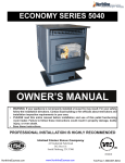
1
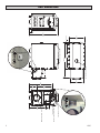
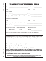
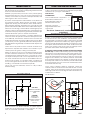
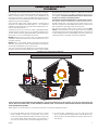
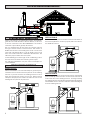
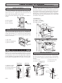
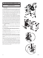
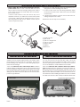
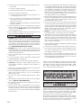
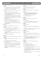
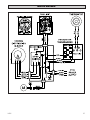
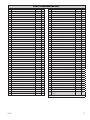
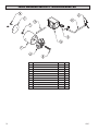
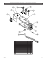
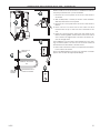
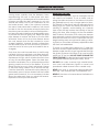
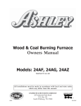
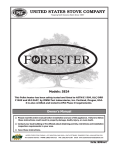
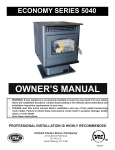
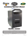
U USSC E STATES ST OV TED I N COMPANY Installation/Operator’s Manual Model: 1600EF Wood or Coal External Furnace SAFETY NOTICE: If this furnace is not properly installed, a house fire may result! For your safety, follow these installation instructions. Contact local building or fire officials about restrictions and installation requirements in your area. This furnace must be installed by a qualified technician. Keep these instructions for future reference. Safety Tested to UL 391 United States Stove Company • 227 Industrial Park Road, P.O. Box 151 • South Pittsburg, TN 37380 • www.usstove.com USSC 851846 rev 0 1 UNIT DIMENSIONS 29-1/2” 2-9/16” 55-5/8” 5-3/16” 45-3/4” 65-1/2” D-RINGS FOR GUY WIRE ATTACHMENT Blower Speed Selector Switch 6” FLUE GAS OUTLET 17-5/16” 24-1/4” 29-3/16” 43-7/16” 14-1/4” Limit Switch Access 10” HOT AIR OUTLET 12” COLD AIR RETURN HOT WATER COIL ACCESS (OPTIONAL) 6” 31-5/8” USSC 2 CUT HERE " WARRANTY INFORMATION CARD Name__________________________________________ Telephone #: (_____)_____________ City____________________________________________ State_______ Zip_________________ Email Address __________________________________________________________________ Model # of Unit________________________________ Serial #___________________________ Fuel Type: qWood qCoal qPellet qGas qOther _________________________ Place of Purchase (Retailer)______________________________________________________ City____________________________________________ State_______ Zip_________________ If internet purchase, please list website address___________________________________ Date of Purchase _______________________________________________________________ Reason for Purchase: qAlternative Heat qDecoration qCost qMain Heat Source qOther _________________________ What was the determining factor for purchasing your new USSC appliance?_______ I have read the owner’s manual that accompanies this unit and fully understand the: Installation qOperation q and Maintenance q of my new USSC appliance. Print Name Signature Date Please attach a copy of your purchase receipt. Warranty not valid without a Proof of Purchase. " CUT HERE Warranty information must be received within 30 days of original purchase. Detach this page from this manual, fold in half with this page to the inside and tape together. Apply a stamp and mail to the address provided. You may use an envelope if you choose. You may register online by going to www.usstove.com All information submitted will be kept strictly confidential. Information provided will not be sold for advertising purposes. Contact information will be used solely for the purpose of product notifications. CUT HERE " Fold Here Fold Here É United States Stove Company P.O. Box 151 South Pittsburg, TN 37380 CUT HERE PLACE STAMP HERE " Ê INTRODUCTION GENERAL INFORMATION Thank You for your purchase of a U.S. Stove Wood/Coal Burning External Furnace. Your decision to buy our Clayton Furnace was undoubtedly reached after much careful thought and consideration. We are very proud you chose this furnace and trust you will receive the comfort and economy that others realize when heating with a U.S. Stove product. Your 1600EF furnace comes ready for installation. No assembly required. Unpack your furnace and insure that there is no shipping damage. If damage exist, please contact your dealer immediately. Review the items included with your furnace located inside the firebox. Your dealer is important in your experience with the furnace not only with the purchase, but for recommendations for professional installation for your home. The qualified professional installer has been expertly trained in solid-fuel furnace installation to assure the safety and comfort for your family while saving you money. Trust your experienced installer. They are specialist in this field. IMPORTANT Before installing and using your furnace, please read the following pages thoroughly and carefully. If you follow the instructions, your furnace will give you safe and more dependable service for years to come. • Check your local codes. This installation must comply with their rulings. • This is an outdoor hot air furnace and must NOT be installed inside the home or a building. • This furnace must be connected to a 110 volt Ground Fault Circuit Interrupter (GFCI) outlet suitable for outdoor use. • A back-up generator, 2,000 watts minimum, is recommended in case of a power failure. • Always have a properly functioning smoke or ionization detector and a CO detector installed in your home. • To prevent injury or damage, do not allow anyone who is unfamiliar with the furnace to operate it. • Spend adequate time with your furnace to become well acquainted with the different settings and how each will affect its burning patterns. It is impossible to state just how each setting will affect your furnace because of the variations in each installation. DISCLAIMER NOTICE The BTU ranges and heating capacity specifications are provided as a guide and in no way guarantee the output or capacity of this unit. The actual BTU output depends on the type of fuel being burned and its conditions, the thermostat setting, the draft adjustment and the chimney to which the unit is attached. The actual area that this unit will heat depends on factors such as the conditions of the building, heat loss, type of construction, amount of insulation, type of air movement, the location of the unit and more importantly the duct work and return air facility. Warning: Do not alter this appliance in any way other than specified in these instructions. Doing so may void your warranty. USSC 1 - 10” Starter Collar 1 - 12” Starter Collar for Cold Air Return 8 - #10 x 3/4 Screws w/ Sealing Washer 1 - Literature Package This furnace may be installed as a Stand-Alone Central Furnace or as a Supplementary Furnace. If installed as a Central Furnace, this unit will have it’s own central ducting system and will essentially be your primary heat source. If installed as a Supplementary Furnace, the 1600EF will assist an Electric, Gas or Oil Fired Furnace in heating your home by utilizing the existing furnace’s duct work system. The 1600EF must not be wired in conjunction with the existing furnace. The outdoor furnace may be operated with the supplied wall thermostat or a 24 volt thermostat that you supply yourself. The furnace should be placed outdoors on a level noncombustible base, preferably a 4’ x 8’ concrete pad, as close to the home as clearances to combustibles will allow. If locating the furnace more than 10 feet away from the home, a minimum of 6 feet of Class “A” HT 2100 All Fuel 6 inch chimney pipe is required - Do not place the furnace more than 40 feet away from the home. Maintain all clearances stated in this manual. Class “A” HT 2100 All Fuel 6” Chimney Pipe is recommended for optimum performance and can be purchased from your local dealer. A Chimney Base Plate should be installed over the flue outlet and sealed to maintain weather resistance. A 2” clearance to combustibles must be maintained from the pipe. We suggest using either Simpson Dura-Vent or Metal Fab chimney products for your installation. If you choose to use single wall stainless, the flue temperatures will be reduced which promotes the formation of creosote, possibly creating a fire hazard. If you use single wall stainless pipe, the minimum clearance to combustibles is 20”. Attach the appropriate chimney pipe lengths to the chosen chimney base plate and finish with a rain cap. Secure the chimney with guy wires to each of the four anchors point on the furnace. Your furnace requires it’s own chimney system and can not share a flue with another appliance. Once you have selected a location for the furnace and connected your furnace to a chimney and a 110 volt GFCI outlet, you will need to commence an initial firing. DO NOT connect the furnace to your duct work at this time. Your new furnace has a protective coating of oil and paint on the surface which could produce smoke or odors during the initial firing and will burn off. Build a small fire - DO NOT fill the firebox to it’s full capacity for the initial burn. This initial firing allows the metals and castings to cure. After completing the firing and allowing it to cool, you are ready to finish the installation. Refer to the remainder of this manual for detailed instructions. 5 WOOD SUPPLY FLUE PIPE INSTALLATION Some important rules for preparing good firewood are: Cut, split and stack the wood in the early spring and let it stand in the sun and wind all summer. Clearances to combustible materials will vary with the type of flue connection used. Be sure to maintain the specified clearances for your type of installation. TYPE OF FLUE REQUIRED CONNECTION CLEARANCE Whether you purchase your wood or cut it yourself, spring is the best time to buy or cut your wood to insure it is good and dry come winter. If you live in a damper climate, it will take longer for the wood to season. By far the most important characteristic of any firewood is its moisture content. Firewood with a moisture content higher than twenty percent will burn, but it will be hard to light and keep burning, will make a lot of smoke and will produce less efficient fires with lower sustained BTU output. Plus much of its energy content will be wasted right up the chimney. Firewood should be between 15 and 25 percent moisture to burn properly and to get that dry it must be split and stacked in the open for at least a full summer. All wood burns, but wood that’s cut green (between 50 and more than 100 percent moisture content) burns with more difficulty, because the water in the wood must be boiled off before the actual wood fiber can burn. Air-dried (“seasoned”) wood is generally between 20-30 percent. Kiln-dried firewood generally contains less than 20 percent moisture. Green wood can produce more creosote--a black sooty liquid which deposits and hardens on the inside of your chimney and can ignite, causing a chimney fire. When you stack your wood, you should stack it in an open location where the summer sun can warm it and breezes can help remove moisture. Be sure to cover the top of the wood pile to keep the rain out. It is important that you do not stack unseasoned wood in an unventilated area for it will not dry properly. You shouldn’t allow your firewood to lay on the ground for more than a couple days before stacking , or it will start to mold and rot quickly. Once your wood is seasoned, store it in a dry location before burning. CLEARANCES Class A 103HT All-Fuel or Equivalent . ....2” Double Wall, Stainless Steel or................6” Double Wall, Black Pipe w/ Stainless Steel Inner wall 24 Gauge or Heavier ..............................20” Single Wall Stainless Steel or Black Pipe The above clearances to combustibles must be maintained. CHIMNEY REQUIREMENTS A Class “A” HT 2100 All Fuel 6” Chimney Pipe and Base Plate should be used for the installation. See Illustration. Place the Base Plate over the flue outlet of the furnace and drill eight(8) pilot holes into the Cabinet Top. Apply a generous amount of high temperature sealant to the bottom of the base plate, and around the flue outlet. Position the base plate over the flue and secure with the eight(8) screws provided. Then attach the flue pipe sections. A minimum chimney height of 6 feet is required not including the rain cap. In order to determine proper chimney height above the roof, measure from the side of the chimney horizontally. As you move up the chimney, the length increases. Once this measurement reaches 10 feet, this is the base height of the chimney. The chimney must be 2 feet taller than the base height. If the chimney is closer than 10 feet from the peak of the roof, the chimney must be 2 feet taller than the peak of the roof. The 2 feet measurement does not include the rain cap. Once correct chimney height is achieved, check the chimney draft. It should not exceed 0.06 inches of water column. Then secure with three screws at each joint and attach guy wires down to the rings located around the top of the furnace cabinet. See illustration. COMBUSTIBLE WALL COMBUSTIBLE WALL 20” 15” (TOP VIEW) 22” FLUE MINIMUM CLEARANCES TO A COMBUSTIBLE WALL CAUTION: 12” DO NOT store combustible or flammable materials or liquids near the furnace. Sides of furnace, 12”; Rear of furnace, 15” (allow approximately 20” for the return box); Front of furnace, 36”; Heat Duct, 2” for the first 9 feet then 1” thereafter. 6 USSC CONNECTING HOT AIR DUCT TO FURNACE We strongly recommend that the hot air duct work be installed by a home heating specialist. If doing the installation yourself, before you decide which installation will best suit your needs, consult a qualified heating technician and follow his recommendations as to the safest and most efficient method of installation. The warm-air supply-duct system shall be constructed of metal in accordance with NFPA 90B, 2-1.1. The plenums installed to the furnace be constructed of metal in accordance with NFPA 90B, 2-1.3. Outside the house you must use 10 inch galvanized pipe, wrapped with weather proof, UV resistant insulation. The 12 inch return may be galvanized pipe and attached to the home so as to not pressurize the home. NEVER reduce the 10” hot air or the 12” return air as this will result in restricted air flow and cause the furnace to not operate properly. NEVER draw cold outside air into the blower housing. By doing so, the furnace’s heat chamber will not reach the necessary temperature to heat the home. The duct work should be designed so the external static pressure does not exceed 0.2 inches water column while developing air velocities of 600 to 1,000 feet per minute in the main trunk duct and 400 to 600 feet per minute at the registers. The heat outlet should never be less than ten inches (10”) round or 79 square inches. This furnace must be installed with a cold air return system. The system must be a minimum of twelve inches (12”) to readily transfer the cold air from the home back to the furnace. If desired, a cold air filter box may be constructed with a minimum opening of 225 square inches. The warm-air supply outlet of the outdoor furnace must not be connected to the cold-air-return inlet of an existing central furnace because the possibility exist of components of the existing furnace overheating and may cause the central furnace to operate other than intended. TYPES OF INSTALLATION NO DUCT WORK INSTALLATION Cold air return must be installed in all installations, even those without an air duct system. If you do not, the furnace will not be able to heat the home. A filter should be installed in the cold air return. Furnace filters should be checked and cleaned/replaced regularly. When there is no duct system to connect the furnace to, keep the following in mind: 1. You must separate the hot air duct from the cold air return. Ideally, locate each at opposite ends of the home. This method will work well in homes that are built on concrete slabs and should create a good air flow. If you do not, air will not flow evenly through the home. USSC 2. In homes with a basement, you may run the hot air duct to the basement and pull the cold air return from the main floor. This will create the perfect air flow since hot air rises. 7 TYPES OF INSTALLATION continued... CENTRAL DUCT CONNECTION When connecting to a central duct system, avoid 90 degree elbows as this will reduce air flow delivery. A duct run in excess of 40 feet is NOT RECOMMENDED. The air flow and heat output will be greatly decreased. INSTALLATION #2 The baffle on this system should be made the full width of the furnace plenum in order to properly direct the air into the distribution ducts. Run 10” insulated hot air duct from the outdoor furnace through a wall or window of the structure. Then attach a flexible hot air duct to the existing duct work. Connect the duct with a 45 degree elbow or at an angle so the hot air from the outdoor furnace is delivered downstream. This will insure proper air flow into the system. Avoid delivering hot air through an air conditioning coil as this will cause an obstruction reducing heat output. The following illustrations may be used as examples for your installation. INSTALLATION EXAMPLES INSTALLATION #1 With this installation, a back draft damper (optional) is inserted into the heat run before the plenum of the existing furnace to prevent air from the existing furnace to blow back into the furnace when it is not in use. When a back damper is employed, it should be located as close to the existing furnace plenum as practical. 8 INSTALLATION #3 Extending the hot air duct from the furnace into the existing plenum will help direct the flow of air from the furnace as well as the flow in the existing furnace. Ducting entering the existing plenum at an angle (approximately 45 degrees) will facilitate air flow from the furnace while diverting air from the existing furnace. USSC FURNACE ASSEMBLY INSTRUCTIONS Read and follow these instructions in the event you have SHAKER GRATE HANDLE to replace or re-assemble components of your furnace. DOOR HANDLES Insert door handle into door. From rear side of door, place a 1/2” washer over the threaded part of the handle, then attach the lock nut. Tighten the nut, then back off 1/4 turn to allow free operation of the handle. Follow these same directions for the ash door handle assembly. Insert the Shaker Rod into the hole on the ash door frame as shown. Then attach the Shaker Bracket to the front of the furnace using two 1/4-20 x 3/4” Hex Bolts and two 1/420 Lock Nuts. Next, insert the shaker Rod into the bracket and attach to the shaker grate bar using the 1/4-20 x 1” Hex Bolt and a 1/4-20 Lock Nut. The bolt and nut retaining the shaker bar and rod should be left loose to allow free movement of the grates. (1) Shaker Rod (1) Shaker Bracket (1) 1/4-20 x 1” Hex Bolt (2) 1/4-20 x 3/4” Hex Bolt (3) 1/4-20 Lock Nut (2) Door Handle (2) 1/2” Washer (2) 1/2” Lock Nut BRACKET ASH DOOR SPIN DRAFT Screw the spin draft onto the 3/8” x 2-1/2” carriage bolt. Then screw the spin draft and bolt into the ash door allowing approximately 1/2” of the bolt to stick through the back side of the ash door. Secure the bolt in place with the 3/8”-16 lock nut. (1) Spin Draft (1) 3/8-16 Carriage Bolt (1) 3/8-16 Lock Nut FUEL & ASH DOOR LATCH With two 1/4-20 x 3/4 hex bolts each, attach the door latches to the door latch mounting brackets on the left side of the door frames as illustrated. The slots in the brackets and latches are for door seal adjustment. Make the proper adjustments, then tighten the nuts. The door’s gasket should be snug against the door frame on the furnace. SMOKE CURTAIN Using two 1/4-20 x 1-1/4” Carriage bolts, the smoke curtain clips and two nuts, attach the smoke curtain in place above the Fuel Feed Door as shown below. After installation, the smoke curtain should swing freely back into the furnace. (1) Smoke Curtain (2) 1/4-20 x 1-1/4 Carriage Bolt (1) Feed Door Latch (1) Ash Door Latch (4) 1/4-20 x 3/4 Hex Bolt (4) 1/4-20 Kep Nut Feed Door Illustration Ash Door Illustration (2) Smoke Curtain Clips (2) 1/4-20 Kep Nut 1/4-20 NUT SMOKE CURTAIN CLIP 1/4-20 x 1-1/4 CARRIAGE BOLT SMOKE CURTAIN NUT BOLT SMOKE CURTAIN CLIP SMOKE CURTAIN FRONT USSC 9 DISTRIBUTION BLOWER & ACC. A All electrical connections should be done by a qualified electrician. 1. To replace the Honeywell Limit Control (A): Unplug from power supply The control may be removable thru the access panel on item “B”. However it may be easier to remove item “B” entirely for better access. Remove item “B” by means of the eight(8) screws. If siliconed, use a utility knife to score the silicone along the edges of the part. Take off the cover of the control (A), remove the three wires, and continue to remove the control by means of the two screws retaining it. Use the wiring diagram in the rear of this manual to re-connect the new control. Reattach item “B” and re-silicone all the seams with weather resistant silicone. 2. B C To remove the return air box (D): Unplug from power supply. If siliconed, use a utility knife to score the silicone along the edges of the part. Remove item “B” as described above. Then remove the four(4) screws down each side and the four(4) across the top of the return air box. Pull the box back away from the unit enough that you can reach in to remove the snap-in plug (C) from the top of the box. The power supply cord will need to be feed back thru the plug in the bottom of the air box for complete removal. When re-attaching, make sure that the three plugs in the top of the Fan Center (G) are properly plugged in. Do not forget to put the snap-in plug (C) back in place. Re-silicone all the seams with weather resistant silicone. 3. E D To remove the Distribution Blower (E): Unplug from power supply. Remove items”B” and “D” as described above. Unplug the blower from the top of the Fan Center (G). Remove the four(4) screws retaining the blower. 4. C To remove the Blower Motor: Unplug from power supply. F H G Perform number 3 above. Before removing the motor from the housing, measure two things: 1.) The distance from the edge of the motor to the edge of the motor bracket. Record (d1) _________________ 2.) The distance of the shaft remaining outside the coupling on the blower wheel. Record (d2) __________________ d1 These two measurements dictate the position of the blower inside the housing and is critical in determining motor longevity. Repositioning of the blower motor, bracket, and wheel in respect to one another should keep as close to the factory position as possible. K I Remove the three(3) screws (I) from the blower housing. Then loosen the bolt (J) on the motor shaft. Next, loosen or remove the bolt (K) in the motor bracket to remove the motor. 5. To remove the Blower Capacitor (F): Unplug from power supply. This may be accomplished by working thru the 12 inch diameter return duct hole in the Return Box. Otherwise, you must remove items”B” and “D” as described above. Unplug the blower from the top of the Fan Center (G). Using pliers with rubber coated handles, unplug the two connections on the capacitor. Remove the two screws and cap bracket. d2 J 10 USSC MOTORIZED NATURAL DRAFT REPLACEMENT 1. Make certain the unit has been unplugged from the power source. Remove the cover from the motor and remove the two wire nuts and grounding screw. With a pair of pliers, remove the strain relief and cord assembly from the motor. 2. Remove the draft assembly from the furnace by loosening the two bolts retaining draw band. 4. If replacing the Flipper, remove the two #8 screws retaining the plate to the tube. If motor comes with the cord, the above step is not required. However, you will have to remove the panel on the inner cabinet side to rewire the motor. Do so by removing the rivets with a 3/16” drill bit. Screws may be used to replace the rivets. 3. To remove the motor from the tubing assembly, simply loosen the set screw in the collar on the motor and slide it off the tube. Reverse the above steps for re-assembly (1) Draft Actuator (1) Spin Draft (1) 3/8-16 Carriage Bolt (1) 3/8-16 Lock Nut (1) Flipper Tube (1) Flipper (2) #8 Screw FIREBRICK AND BAFFLE REPLACEMENT FIREBOX BRICK REPLACEMENT BAFFLE/BRICK REPLACEMENT This furnace comes from the factory with the firebrick installed. However, if brick replacement is necessary, follow these instructions. Before furnace operation, remove the brick retaining strip. This piece is used during shipping to reduce brick damage. If baffle replacement is necessary, slide the baffle out until you can access the nuts thru the flue outlet. Once the nuts have been removed, slide the baffle off the rod and thru the opening in the firebrick. You may have to remove one of the firebrick to make baffle removal easier. There are 6 full brick and 1 half brick per side. Install the half brick first by putting the bottom of the brick in first and let it rest against the firebox side and fire grates. Then slide it to the rear. After that, install the #2, #3, #4, #5 & #6 brick, sliding the 6th brick forward to allow for the 7th brick. Repeat for opposite side. There are 4 full brick and 1 half brick in the top of the furnace. Install the brick by inserting one end of the brick angled upward and then allowing the opposite end to rest on the firebox lip. Lay the brick between the spacer and firebox back. Slide the baffle to the rear and let it rest on that half brick. After installing brick #2 in the front, install #3 and slide it under the baffle. Finally install bricks #4 and #5. NOTE: Prior to operation, be sure to remove the brick retaining strips. USSC 11 TESTING AND OPERATING PROCEDURES 4. Load the furnace, close the load door and push the slide GENERAL FURNACE OPERATION After installation of the furnace is complete, it is ready for operation. The Honeywell Limit Control, in conjunction with a wall thermostat, operates the distribution blowers and the motorized draft on the front of the furnace. The limit control is located on the rear of the furnace in the upper left corner and is accessible by removing the two screws in the cover plate. DO NOT operate your furnace with this plate removed! The control can be adjusted to your desired blower On/Off times. The factory settings are 100/150/200. The wall thermostat setting operates the ON time of the motorized draft. If the temperature is below the setting on the wall thermostat, the motorized draft will come open. (Recommended setting at 5 to 10 degrees higher than other heating thermostats.) The first two set points on the limit control operates the distribution blower. When the furnace plenum reaches the second set point on the limit control, the distribution blower will come on. If the temperature falls to the first set point, the distribution blower will shut-off. The distribution blower is a three speed blower and can be manually adjusted by means of the three position switch located behind the sliding access panel on the cold air return box. When the furnace reaches the third set point on the limit control, the draft blower will shut-off. The draft blower will come back on if the temperature falls below the setting on the wall thermostat. TESTING 1. Check the motorized draft by turning the room thermostat up high enough so that the motorized draft opens. Then lower the thermostat setting to ensure it closes off. 2. Use a sheet of newspaper to test your draft by placing it inside the furnace and lighting it. With completion of the tests above, you are ready to light the furnace. Follow the operating steps. STARTING A WOOD FIRE Using Motorized Natural Draft CAUTION: Never use gasoline, gasoline-type lantern fuel, kerosene, charcoal lighter fluid, or similar liquids to start or “freshen up” a fire in the furnace. Keep all such liquids well away from the furnace while it is in use. 1. Open spin draft cap on ash door. 2. Pull the slide baffle rod to the front position. 3. Open the fuel load door and light fire using kindling and several sheets of newspaper, then close the furnace door. The furnace door should remain closed for 5 to 10 minutes in order to establish the fire. If the fire has established, you are ready to load the furnace. CAUTION: To prevent flame and smoke spillage, the slide baffle must be pulled out and the fuel door must be cracked for ten seconds before being fully opened. Do not over fire your furnace! After you have become familiar with its operating, you should know how much wood to use. 12 Baffle rod to rear. 5. Close the spin draft cap on ash door, leaving it cracked about the diameter of a dime. 6. The motorized draft cycles (opened & closed) on demand from the wall thermostat. Setting the U.S. Stove thermostat four degrees higher than your existing thermostat is recommended. In operation, the power draft will remain open until the U.S. Stove thermostat temperature setting is reached. Then it will close to reduce combustion air. If the furnace looses power, the draft will automatically close. CAUTION: To avoid excessive temperatures, do not operate with fuel door or ash pan open. STARTING A COAL FIRE Shut off FAD when fuel door is open Open all draft controls on your furnace. Pull the slide baffle forward. Place about 10-15 lb. of coal in on the shaker grates. It should come up to about half of the first firebrick level. Place crumpled paper over the coal and crisscross a couple handfuls of dry kindling wood 3/4” in thickness on top of paper. Ignite the paper and close loading door. Wait about 30 minutes until coal fire is established before adding more coal. NOTE: NEVER load coal over the level of firebrick. Close by-pass damper and set all draft controls to your own needs. It may take 3 to 4 coal fires to determine how your local coal and the Clayton Furnace reacts together. Adjusts drafts accordingly. When loading with a good bed of coals in the morning - Open by-pass damper. 1. In normal shaking, only rock the grates a small amount to sift ash through. Do not agitate the fire bed too often. This practice will waste coal. If glowing coal is visible in the ash pan, you have shaken to much. 2. Remove all ashes every day from ash pit. CAUTION: Ashes should be placed in a metal container with a tight fitting lid. The closed container of ashes should be placed on a non-combustible floor or on the ground well away from all combustible materials pending final disposal. If the ashes are disposed of by burial in soil or otherwise locally dispersed, they should be retained in the closed container until all coals have thoroughly cooled. 3. With your poker, push hot burning embers to the rear of the unit and add green coal in front. NEVER load over height of firebrick. This can result in damage to your furnace and home. 4. Close by-pass damper. Too much draft air will cause clinkering of coal and will waste heat up the chimney. Shut draft down to as low a point as you can and still heat your home. 1. NOTE: Never stand in front of loading door when opening it. Stand to the side. 2. NEVER completely cover the live fire with fresh coal. Always leave a generous area of glowing coal at the top of the fire and at the rear. 3. Always keep the ash pit clean. USSC If the fire goes out or does not hold overnight, look for: 1. Poor draft. 2. Incorrect damper settings. 3. Improper firing methods for coal being used. 4. More combustion air needed. 5. Coal not sized to the furnace. We recommend 1” to 3” diameter pieces of coal. 6. Ashes, if allowed to accumulate in the ash pit, will not allow the passage of required air for combustion. Keep ash pit clean. 7. This furnace is not to be used with an automatic stoker unless so certified. There are ONLY two types of coal allowed for use in this furnace: Bituminous Coal (soft coal) and Anthracite Coal (hard coal). NEVER USE Cannel (or Channel) coal or Brown (Lignite) Coal. See our Bulletin RC454 at the rear of this manual for the best information available on burning coal. OPERATING NOTES DANGER: Risk of Fire or Explosion - Do not burn garbage, plastics, gasoline, drain oil or other flammable liquids. Plastics, when burned, form hydrofluoric and hydrochloric acids which will damage and destroy your furnace pipe and chimney. The burning of trash or oil can result in an extremely hot fire and is sometimes a cause of chimney fires. NEVER BURN GREEN WOOD OR TIRES. WARNING: Risk of Fire - Do not operate with flue draft exceeding .06 inches of water column and must be set with a draft gauge to maintain a steady draft. (Barometric Damper recommended.) Do not operate with the fuel loading or ash removal doors open. Do not store fuel or other combustible material within marked installation clearances. Inspect and clean your flues and chimney regularly. CAUTION: Hot Surfaces - Keep children away. Do not touch during operation. Maximum draft marked on nameplate. Equip your home with fire extinguishers and smoke detectors appropriately located. Wood should be placed directly onto the cast iron shaker grate of the Clayton furnace. Do not use additional grates and/or irons. Do not allow ashes to build up higher than 2” above grates. Never allow the ashes in the ash pan to touch the grate section. REMOVE ASHES FREQUENTLY! Be extremely careful when removing furnace ash pan; it can get very hot. With new steel, there is a small amount of oil or dirt on the metal. You may smell an odor. This is normal during the first operation. You may want to build a small fire in the furnace to “burn off” this dirt and oil before installing the duct work. USSC The furnace is designed to burn air dried wood and coal at a predetermined firing rate. Over firing could result in damage to the heat exchanger and cause dangerous operation. Over firing occurs when the ash door is left open during operation or a highly volatile fuel, i.e. large amounts of small kindling, is used. If any portion of the connector pipe glows orange or red, you are in an over-firing situation. Close all dampers. When tending the firebox always pull the baffle slide rod out prior to opening load door. Open load door slowly to avoid a “flash back”. After closing load door, push the baffle slide rod to the rear. In event of chimney fire, shut all draft controls and call your fire department immediately. Alert everyone in the house. If the fire is still burning vigorously, throw baking soda into firebox or discharge a fire extinguisher into the firebox. After chimney fire is over, completely inspect system for damage before further use. NEVER throw water on the fire or at the furnace, as rapidly expanding steam could result in a severe scalding. Slow fires: It is not recommended burning the Clayton furnace any more than necessary early in the fall and late spring, as you cannot keep the firebox hot enough (without overheating your home) to burn gases. Slow fires can cause excessive creosote build-up in smoke pipe, chimney and firebox. Inspect air filters regularly. The air filter should be changed at least every 30 days. Oil motors every 90 days with a few drops of 30 wt. oil. Check the fit on the load door. It must fit tightly. If it does not, check for deterioration or wear of the ceramic rope seal. Replace defective seals. In the event of a power failure, the furnace will not distribute heat to the home. We recommend the use of a back-up generator, 2,000 watts minimum, for continued use until regular power is restored NOTE: For further information on using your furnace safely, obtain a copy of the National Fire Protection Association publication “Using Coal and Wood Stoves Safely.” NFPA NO. NW-8-1974. The address of the NFPA is 470 Atlantic Ave., Boston, Massachusetts 02210. THIS IS A WOOD AND COAL BURNING FURNACE AND SHOULD NOT BE ALTERED IN ANY WAY! DOING SO WILL VOID YOUR WARRANTY! CREOSOTE - FORMATION AND NEED FOR REMOVAL When wood is burned slowly, it produces tar and other organic vapors, which combine with expelled moisture to form creosote. The creosote vapors condense in the relatively cool chimney flue of a slow-burning fire. As a result, creosote residue accumulates on the flue lining. When ignited, this creosote makes an extremely hot fire. The chimney should be inspected at least twice monthly during the heating season to determine if a creosote buildup has occurred. If creosote has accumulated, it should be removed to reduce the risk of a chimney fire. 13 TROUBLE SHOOTING AND PROBLEM SOLVING 1. Problem: 4. Problem: Smoke puffs from furnace Distribution blower vibrating Solution: Solution: A. Check chimney draft. Check for blocked chimney or flue pipe. Use mirror to check chimney clearance. A. Tighten blower wheel to motor shaft. B. Check for bad fan bearings. B. Check ash pit — if it is too full, empty. 5. Problem: C. Make sure all of chimney mortar connections are airtight. Distribution blower continues to run or will not run D. Check ash drawer. Make sure it’s airtight. E. Check chimney for possible down-draft caused by taller surrounding trees or objects. Correct with proper chimney vent cap. F. Check the possibility of a cold chimney forcing cool gases backward. Remedied by properly insulating chimney with non-combustible liner — non-combustible insulation. G. Fuel may be too green. H. Make sure no other fuel burning devices are connected to the chimney impairing the draft. I. Check chimney draft, it should be .06 inches of water column. This service is provided by a certified chimney sweep. 2. Problem: Inadequate heat being delivered to your home Solution: A. Check home insulation — is it adequate? B. Check hook-up to furnace — is it installed correctly? C. Cool air inlet may be inadequate. D. Your wood fuel may be too low grade. Hardwoods are recommended. E. Make sure your hot air duct (and other duct work) is airtight. F. Is air to the blower available? 3. Problem: Excess smoke or flames coming out door when refueling Solution: A. Wait 15 seconds and open door SLOWLY — then refuel. B. Check length of flue pipe to chimney. C. Make sure chimney cap is not too close to the top of the chimney. Solution: A. Check fan limit or heat sensor and cable. B. Check to see that blower is properly wired. (See Wiring and Assembly Instructions). C. Check fuse box or power source. D. Check power supply. 6. Problem: Motorized draft stays open or will not close Solution: A. Check wiring. B. Check thermostat or thermostat wire for short. C. Make sure temperature is calling for heat. 7. Problem: Odor from first fire Solution: A. The odor from new steel should disappear in a few hours. B. If the odor remains, call you dealer immediately. A bad weld can cause a fume leak. 8. Problem: Excessive Creosote Solution: A. Check the grade of wood you are burning. B. Make sure your unit is serviced by its own proper chimney. C. Check length of flue pipe and its connections. D. Make sure you are burning the smallest, hottest fire to adequately heat your home. E. Also see Solutions to Problem number 1. 9. Problem: If the fire goes out or does not hold over night Solution: D. Check chimney draft — make sure chimney flue pipe is clean and chimney is of adequate height. A. Poor Draft. E. Make sure you’re not suffocating the fire with excessive amounts of unburned wood. C. Improper firing methods if burning coal. F. Slide baffle should be pulled out prior to load door opening. E. Coal not sized to the furnace. We recommend 1” to 3” diameter pieces of coal. B. Incorrect damper settings. D. More combustion air needed. F. Ashes, if allowed to accumulate in the ash pit, will not allow passage of the required air for combustion. Keep ash pit clean. G. This furnace is not to be used with an automatic stoker unless so certified. 14 USSC WIRING DIAGRAM USSC 15 PARTS DIAGRAM 16 USSC PARTS DIAGRAM AND LIST Key Description Part # Qty Key Description Part # Qty 1 Grate Retainer 40312 2 41 Inner Top 25726 1 2 Shaker Bar 891341 1 42 Insulation, Top-Front 88150 1 3 Shaker Grate Section 40314 5 43 Insulation, Top-Middle 88151 1 4 Front Liner 40344 1 44 Insulation, Top-Rear 88152 1 5 Back Liner 40313 1 45 Mount, Flue Outlet 25727 1 6 Full Firebrick (4-1/2 wide x 9 tall x 1-1/4 thick) 89066 16 46 Weldment, Cabinet Top 69648 1 7 Half Firebrick (2-1/4 wide x 9 tall x 1-1/4 thick) 891414 3 47 D-Ring Clip 83912 4 8 Slide Baffle 24231 1 48 Bottom Intake 25722 1 9 Baffle Rod 86662 1 49 Assembly, Cabinet Door 69649 1 10 Inside Cover Plate 24220 1 50 Latch, Cabinet Door 891865 1 11 Gasket, Water Coil Cover C97999 1 51 1800 CFM Blower Assembly 80590 1 12 #12 x 3/4: Tek Screw C23799 3 N/S 1/4-20 x 3/4 Self Tapping Screw 83236 4 13 Carriage Bolt, 1/4-20 x 1-1/4 Long 83445 2 N/S Washer 83045 4 14 Smoke Door Clip 23787 2 52 Blower Motor 80588 1 15 Kep Nut, 1/4-20 83250 2 53 Fan Center Assembly 69651 1 16 Smoke Curtain 23800 1 54 Honeywell Limit Control 80145 1 17 Door Handle 891884 2 55 Harness, 3 Circuit Plug 80586 1 N/S Lock Nut, 1/2-13 83444 2 56 7/8” Snap Bushing-Heyco (BLK) 83909 3 N/S Washer 83835 2 57 Cable Chase 25732 1 18 Feed Door Latch 23786 1 58 Gasket, Access Panel 88155 1 19 Feed Door Assy. (w/Rope Gasket) 69653 1 59 Probe Access Panel 25733 1 20 Shaker Handle 69005 1 60 Cover, Water Coil 25725 1 21 Bracket, Shaker Handle 24204 1 61 Bottom, Blower Box 25734 1 22 Ash Door Latch 23823 1 62 1-1/4” Bushing, Heyco 83910 1 23 Ash Pan 68882 1 63 Right Side, Blower Box 25737 1 24 Carry Handle 24233 1 64 Left Side Assy., Blower Box 69650 1 25 Ash Door Assy. (w/Rope Gasket) 68880 1 65 Back, Blower Box 25736 1 26 Draft Cap 23859 2 66 Top, Blower Box 25735 1 27 Outer Side Wall, Left 25715 1 67 MTG. Bracket, Blower Box 25741 2 28 Panel-L, inner Cabinet 25746 1 68 Motorized Natural Draft (MND) Assembly 69654 1 29 Clip, Outer Wall 25718 2 N/S MND Motor 80592 1 30 Bracket, Alignment 25719 2 69 3” Draw Band 23888 1 31 Cabinet Door Stop 25720 1 70 1/4-20 x 1” Hex Bolt 83379 2 32 Insulation, Cabinet Side 88149 4 71 1/4-20 Lock Nut 83261 2 33 Outer Side Wall, Right 25715 1 72 Plate, Electrical Connection 25745 1 34 Panel-R, inner Cabinet 25717 1 73 Strain Relief Bushing 80154 1 35 Harness, 2 Circuit Plug 80587 1 74 Hook, Handle 25748 1 36 Filler, Top 25721 1 75 Handle, Separable 891884 1 37 Hood, Front 25744 1 76 12” Stub Collar 89799 1 38 Assembly, Cabinet Back 69647 1 77 10” Stub Collar 891868 1 39 Insulation, Back 88153 1 N/S 83572 96 40 Insulation Holder 83884 16 #10 x 3/4 Tek Screw w/ Bonded Neoprene Washer USSC N/S = Not Shown 17 PARTS DIAGRAMS AND LISTS - MOTORIZED DRAFT KIT 4 Key 18 Description Part # Qty 1 Weldment, Draft Tube 68872 1 2 Spin Draft 40379 1 3 3/8-16 x 2-1/2 Carriage Bolt 83503 1 4 Lock Nut, 3/8-16 83274 1 5 Actuator, Motorized Draft 80592 1 6 Tube, Flipper 23899 1 7 Flipper 23898 1 8 #8 x 1/2 Tek Screw, Hex Head 83455 2 9 Strain Relief 80154 1 10 Power Supply Cord 80593 17 in. 11 Male, Tyco Terminal 80382 2 USSC PARTS DIAGRAMS AND LISTS - FAN CENTER CONTROL Key USSC Description Part # Qty 1 Electrical Box Cover 25742 1 2 Electrical Box Body 25743 1 3 Switch, 3-Position 80361 1 4 Harness, 6 Circuit Receptacle 80583 1 5 Harness, 3 Circuit Receptacle 80584 1 6 Harness, 2 Circuit Receptacle 80585 1 7 Transformer, Fan Center 80130 1 8 Strain Relief 80154 1 9 Power Supply Cord 80232 1 10 #10 x 1/2 Sheet Metal Screw 83172Z 13 11 Washer, Internal tooth, #10 83240 1 19 NOTES 20 USSC DOMESTIC HOT WATER COIL KIT - OPTIONAL This Furnace will accept the installation of a Domestic Hot Water Coil Kit. The U.S. Stove kit is a 1124 Water Coil and it may be purchased from your local dealer. 2 1. Remove the access panel on the rear of the furnace enclosure. 2. With a utility knife, cut away a section of the insulation directly behind the access panel. 1 3. Remove the cover plate from the rear of the furnace firebox. ACCESS PANEL 4. Place one nut on each end of the water coil and thread each nut up to the end of the threads on the coil. 5. Insert the coil through the holes from the inside of the firebox. Install a gasket, washer and nut onto each end of the water coil. Tighten the nuts down securely to insure an air tight seal. 3 The installation is now ready to be plumbed to your existing hot water system. Choose one of the three methods described in the Hot Water Coil instructions. 6. Remove knockouts from the access panel and re-attach to the furnace enclosure. REAR WALL OF FIREBOX 5 Have a qualified plumber connect your domestic hot water pipe to the coil with the appropriate fittings. 4 DOMESTIC HOT WATER COIL 1. NUT 2. WASHER 3. GASKET USSC TURN INSIDE NUTS UP TO END OF THREADS 6 21 BULLETIN RC454 A GUIDE TO BURNING COAL IN YOUR FURNACE Furnaces that are capable of burning coal usually will burn both Bituminous and Anthracite coal. Anthracite is perhaps the best coal fuel because of its long even burn time, high heat output, and cleanliness which make it a good choice for the home. However, keep in mind it is a much more difficult fuel to use, requires more care and patience, is not so widely available, and is usually much more expensive than Bituminous. SIZE OF COAL: Most sizes of Bituminous Coal will work in a coal furnace; for best results we recommend large “nut” coal to small “egg” coal (1-3/4” diameter to 4” diameter). When burning Anthracite, use “egg” or “broken” with sizes between 2-5/16” thru 4-3/8”. Note that it is important to the long life of your stove to buy coal which has been sized and cleaned. Cleaning insures removal of rocks and other minerals. Never use coal smaller than 1” or larger than 5” in diameter. Small sized coal will smother the fire. Too large a size of coal will not burn well. STOVE OPERATION: All coal fires should be started with wood which will allow the fire to get hot enough to ignite the coal. The best ignition fires utilize dry pine or other resinous soft woods as kindling, with hard wood (oak, hickory, ash) added to increase the heat prior to addition of the coal. Before starting the fire, open the stove pipe damper (if equipped), turn the thermostat to high, open the ash pit door and feed door, place newspaper and finely split kindling on the grate, light the paper, add larger hard wood after the kindling is burning brightly. CAUTION: Never use gasoline, lantern fuel, kerosene, charcoal lighter fluid, or other flammable liquids to start or freshen up a fire in any heater. Place the larger pieces of wood on the fire so that they are slightly separated and form a level for the addition of coal. It will take 10 to 20 minutes before this wood is thoroughly ignited. Adding coal too soon will cut the air supply and smother the fire. orange or yellow and produce quite a bit of smoke. As the gases burn off the flames become shorter, change color and produce less smoke. Once the fire is WELL ESTABLISHED add coal to the center of the firebox forming the cone. Burning in this fashion allows heat to drive off the volatile gases, and turbulence created increases the burn efficiency. There will have to be some experimenting with the individual setup as no two chimney’s or installations are going to be the same. Just remember to allow enough air to enter the firebox and keep the stove pipe damper open so that volatiles are properly burned. Before refueling, take the time to break up the cone a little with a poker, especially if it has caked over or formed a crust. But, be careful not to mix the coal as this increases the chances of forming clinkers. When shaking the grate(s) be gentle. Just a few short movements - a couple of “cranks” - is better than a lot of agitation. The objective is to remove a small amount of the ashes without disturbing the fire. Stop when you see a glow in the ashes or the first red coals fall into the ash pan. Excessive shaking wastes fuel and can expose the grate(s) to very high temperatures which can cause warpage or burnout. For overnight operation (long duration burn time) shake the fire and add coal, retaining the center cone. Once the volatiles are burned off, close the feed door and adjust the stove pipe damper, if equipped. Then adjust the thermostat to the desired heat level. More MAINTENANCE will be needed with bituminous coal than with anthracite coal as more soot will collect on heating surfaces and in pipes, requiring more frequent cleaning. ANTHRACITE: BURNING BITUMINOUS: Add a thin layer of coal (preferably smaller chunks) to the wood fire, being careful not to disturb it too much or cut off the draft. Then, add a second heavier layer after the coal is ignited and burning well. If necessary, add a third layer to bring the coal up to the top of the front liner (not above!). Be sure to close the ash door. Once your kindling and wood fire has produced a bed of well established coals, start adding coal in layers allowing each to ignite before adding more. Bituminous has a high volatile content and, as a result, should be fired with the “conical method” - with the highest portion of your fire bed in the center of the firebox. The first flames will be long and generally Before adding further fuel, be sure to leave a red spot of glowing coals in the center of the firebox to insure that the fire has not been smothered and to help ignite the gases given off by the new charge. A deep charge will give a more even heat and a longer fire, but it may take one to two hours before the whole bed is fully ignited. 22 USSC BULLETIN RC454 A GUIDE TO BURNING COAL IN YOUR FURNACE When the fire is well established and the room is becoming warm, partially close the dampers. Some experimenting will have to take place with each particular setting of all dampers and controls as the chimney provides the draft necessary to not only exhaust the smoke, but to pull combustion air into the heater as well - and no two chimney’s perform the same. Under ideal draft conditions, one should be able to turn the secondary air supply below the feed door (some models) to a near closed position but leave the ash pit damper at least partially open to prevent the fire from going out. Adjust the stove pipe damper to reduce the draft on the fire. With anthracite there will be short blue flames above the coal, except when the fire is started or a new charge is added. If, however, there is no flame then the fire needs more air from the bottom (unless it is near the end of its burn cycle and needs to be recharged). Only when the coal is burned down to half its original depth it is time to add fresh coal. When doing so, open the stove pipe damper and turn the thermostat damper to high, which will allow the fire to burn off any accumulated gases. Open the feed door, and with a small rake, hoe, or hooked poker pull the glowing coals to the front of the firebox. Try not to disturb the fire too much. Next, add a fresh charge to the back being careful not to seal off the top. Close the feed door, but leave the spin damper (or thermostat) open for a few minutes until the volatile gases have burned off. It is not necessary to shake down the ashes each time you refuel the furnace. Experience will be your best teacher. USSC BANKING THE FIRE: For extended operation, such as overnight, the fire will need to be banked. To do so heap coal up along the sides and back of the firebox so that the fire gradually burns it over a longer period of time. The intensity of the fire will also be reduced without letting it go out. Follow the same procedure as for refueling. If possible, avoid shaking, as a heavier layer of ash will help reduce the intensity of the fire during this time. After loading, let the fire establish itself for about 30 minutes. Then close your damper and automatic control to the point where the house does not become too cold. It is important that you begin banking early enough before retiring or leaving that you can make necessary adjustments after the fire is well established. To revive a coal fire that is almost out, (1) open the ash door and stove pipe damper and close the spin damper under the door to get a good draft through the grate. (2) place a thin layer of dry coal over the entire top of the fire. DO NOT POKE OR SHAKE THE FIRE AT THIS TIME! (3) after the fresh coal has become well ignited shake the grate (just a little), refuel. DO NOT burn coke, charcoal, high volatile bituminous coal, sub bituminous, lignite or cannel coal (sometimes called channel coal or candle coal). NEVER burn wax or chemically impregnated sawdust logs - their intended use is for fireplaces only. NEVER fill the stove or furnace above the firebrick or cast iron liner. 23 HOW TO ORDER REPAIR PARTS This manual will help you obtain efficient, dependable service from the furnace, and enable you to order repair parts correctly. Keep this manual in a safe place for future reference. When placing an order or for warranty claims, please provide the following information found on the Certification Plate located inside the cabinet door. PART NUMBER PART DESCRIPTION MODEL NUMBER______________ SERIAL NUMBER______________ United States Stove Company 227 Industrial Park Road P.O. Box 151 South Pittsburg, TN 37380 (423) 837-2100 Customer Service: (800)-750-2723 • Repair Parts: (888) 299-1440 24 USSC