1
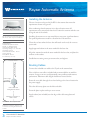
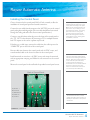
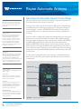
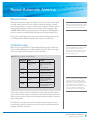
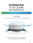
Winegard® Dealer Training
Over-the-Air (OTA) TV Antennas
1
1
1
1
2
Overview
Over-the-air Programming
Receiving Programming with an OTA Antenna
OTA Channels
Winegard OTA Antennas
3
3
3
3
4
5
6
Rayzar® Automatic Antenna
Roof Location Requirements
Installing the Antenna
Routing Cables
Installing the Control Panel
Operating the Rayzar Automatic Antenna
Troubleshooting
®
7
7
7
8
10
10
Sensar & Rayzar® Air Antennas
Roof Location Requirements
Installing the Mounting Bracket & Crank
Wiring the Antenna
Operating the Sensar & Rayzar Air Antennas
Maintenance
11
11
12
12
12
Rayzar® Air Retrofit Kit
Replacing an Existing Antenna
Leak Testing
Troubleshooting
Troubleshooting Hints and Tips
14
14
14
14
14
15
15
15
RoadStar™ Antenna
Warning
Roof Location Requirements
Choosing a Mounting Option
Mounting Option 1 Tips
Mounting Option 2 Tips
Wiring the RoadStar Antenna
Operating the RoadStar Antenna
16
16
Rayzar® Portable Antenna
Setting up the Rayzar Antenna
17
17
17
SensarPro® TV Signal Strength Meter
Installing the SensarPro Signal Meter
Operating the SensarPro Signal Meter
18
18
18
Sensar Replacement Parts and Upgrade Kits
Replacement Kits
Upgrade Kits
Overview
Multicasting is the transmission of
multiple OTA channels on the same
digital signal. A broadcast station may
multicast multiple sub-channels in
addition to the primary channel. For
example, a station normally broadcasts
the regular newscast on its primary
channel, 6-1. On a sub-channel, 6.2,
the same station broadcasts live radar.
Over-the-air Programming
Over-the-air (OTA) programming is programming that is transmitted
wirelessly by local broadcast stations. OTA programming is transmitted
on VHF (very high frequency) or UHF (ultra high frequency) bands and
received by OTA antennas, which send the signal via coax cable to the
television. The advantage of OTA programming is that the programming is
multicasted in pure, uncompressed, free HD.
To find the best reception with a
portable OTA antenna such as the
Rayzar antenna, the antenna should be
tried in multiple locations, and a channel
scan should be run in each location.
FIGURE 4.1. Transmission of signal from broadcast tower to antenna on RV
First time users must run a channel
scan after connecting the antenna to
the TV in order to receive maximum
programming. Run a channel scan
anytime the antenna is in a new
location, as well.
A new scan will find any new channels
that have been added in the your
area as well as finding any channels
that have changed or moved. While
the steps to perform a channel scan
may vary from TV to TV, below are
some general guidelines to follow.
For more specific instructions, refer
to your television owner’s manual for
assistance.
Complete the following steps to run a
channel scan:
1. Using the television remote that
came with the TV or converter
box, select “Menu.”
2. Select “Channel Setup” (if you have
a converter box, skip to step #4).
3. Select “Antenna” or “Off-Air
Mode” or “Auto Scan.”
4. Select “Channel Search” or
“Channel Scan.” Scan time will
vary based on the number of
channels available in your area.
1
Over-the-Air TV Antennas
Overview
Receiving Programming with an OTA Antenna
To receive maximum programming, the OTA antenna should be pointed in the
direction of (a) broadcast tower(s). Depending on the antenna, the antenna may
be pointed between broadcast towers to receive programming from multiple
broadcast towers. Omnidirectional antennas receive signal from all directions
and therefore do not need to be pointed. Once the antenna has been pointed, a
channel scan should be run on the TV. To keep the channel line-up up-to-date,
a channel scan should be run anytime the antenna is in a new location.
OTA Channels
OTA antennas can receive programming from the major local broadcast
networks (e.g., ABC, CBS, FOX, NBC, PBS) plus additional networks
(Qubo, ION, The CW, This TV, MyNetworkTV, Azteca, Telefutura,
Univision, and Telemundo). OTA antennas can also receive local news,
weather, and educational programs that satellite and cable don’t offer. The
number of channels will vary by location. Generally, if you are in or near a
metropolitan area, you will receive more channels than if you are outside
a metropolitan area. Keep in mind that antenna reception may vary based
on terrain (including trees, building, hills, and mountains). The fewer
obstructions, the better your chance for receiving strong digital signals.
Overview
Winegard OTA Antennas
Winegard offers a variety of OTA antennas for mobile applications. The
primary OTA antennas that Winegard offers for mobile applications include
the Rayzar Automatic, Sensar, Wingman®, Rayzar Air, Rayzar Indoor
Portables, and RoadStar antennas.
Sensar III
TABLE 4.1. Available Winegard OTA TV Antennas
Rayzar Automatic
Sensar IV
Automatic Directional Amplified
TV antenna eliminates the hassle
of searching for available TV
signals by automatically tuning in
where most channels are found.
Features an ultra sleek profile and
dome protects elements from
harsh environmental conditions.
VHF/UHF digital roof-mounted
antenna with a range* of up to
55 miles. The Winegard Sensar
IV antenna (shown) includes an
integrated Wingman antenna.
Wingman
Optional accessory for Sensar III
antenna that attaches to antenna,
optimizes antenna for UHF
channels, and increases UHF
performance up to 100%.
Rayzar Air
High-band VHF & UHF digital
roof-mounted antenna that is
amplified and bi-directional. The
antenna is offered in black and
white models as a standalone or
retrofit kit to replace an existing
Sensar antenna.
Rayzar Indoor
Portable
Ultra thin, portable HDTV
antenna that is available in
amplified and non-amplified
models. Amplified models
include attached USB power
supply, 3′ USB cable, 12 V
adapter and 110 V wall adapter.
RoadStar
VHF/UHF amplified omnidirectional outdoor TV antenna
with a range* of up to 35 miles.
Models are available in black or
white models.
Sensar III
with Wingman
FIGURE 4.2.
Add the Wingman for increased
UHF reception with the Sensar III.
Winegard also offers the SensarPro TV
signal strength meter as an accessory
for the Sensar and Rayzar Air antenna.
The signal meter simplifies the search
for digital signal and displays the signal
strength for channels (see fig. 4.2).
(Back)
FIGURE 4.3. SensarPro TV
signal strength meter and
a 2nd booster adds more
amplification.
*Antenna mileage figures are based on average terrain. Actual receiving distance will vary
based on transmitting power, transmitting antenna tower height, pattern of transmitter,
height of receiving antenna, weather conditions and terrain between receiving path including
trees, buildings, hills, mountains, etc.
Over-the-Air TV Antennas
Overview
2
Rayzar Automatic Antenna
Installing the Antenna
Choose a location on the roof of the RV for the antenna that meets the
requirements shown in Figure 4.5.
FIGURE 4.4. Rayzar Automatic
Do not attempt to install this system in
the rain or under any wet conditions.
Specifications:
VHF/UHF Amplified antenna:
Height: 7”; Weight: 4.5 lbs
UV-protected plastic dome
Operating Voltage: 10 – 13.8 VDC
Operating Current:
Park Cable Mode (Off): 10 mA
Active: 500 mA
Sleep Mode: 80 mA
For stationary use only.
≥24″ to front of vehicle
Front of vehicle
≥12″ to edge
of vehicle
Coax connection
facing back of vehicle
Minimum roof space of
18.5″ x 18.75″
FIGURE 4.5. Roof requirements
Rotate the antenna so that the coax
connection is facing the back of the
vehicle.
3
Over-the-Air TV Antennas
Rayzar Automatic Antenna
After confirming that the antenna in its chosen location meets all
requirements, trace around each base foot. Position the antenna with the coax
facing the rear of the vehicle.
Installing the antenna on or near metal objects may cause signal interference.
For optimal performance install in a location free of obstructions.
Clean the roof area where the base feet will attach to the roof; do not erase
your marks.
Apply approved sealant in the areas marked for the base feet.
Align the antenna feet with the areas marked for the base feet, and place the
antenna on the sealant.
Install three mounting screws per antenna foot, and tighten.
Routing Cables
Connect the included coax cable to the F-jack on the antenna base.
Note: a 20 foot coax cable is included and recommended for use with the
antenna. Longer coax runs could potentially cause problems with antenna
performance. Maximum cable length should never exceed 30 feet.
Route the coax cable through the roof and ceiling to the chosen location for
the power supply
Place the cable entry plate over the hole and cable.
Screw the plate in place with up to seven screws.
Apply sealant (not included) over the edge of the cable entry plate and
screws.
Rayzar Automatic Antenna
Installing the Control Panel.
Choose a location for the control panel. Drill a 2” hole, centered, to allow for
installation of control panel power and coaxial connections.
Connect the coax cable from the antenna to the “ANT IN” port on the control
panel, and tighten until fingertight. (The coax cable should have been routed
through the ceiling and wall to the chosen control panel location.)
Connect a coax cable from either the port on the front of the control panel or
the “TV OUT” to the television. If connecting to TVs in multiple locations
both TV outputs can be used or a splitter may be used.
If removing an existing antenna,
supplied with this antenna is a roof
cover plate and ceiling cover plate.
Make sure to properly seal the roof
plate to the roof, including around
the supplied grommet. The ceiling
plate can mount to ceiling after
removing existing crank handle.
Mount the ceiling plate bracket to
ceiling with 2 screws. Ceiling plate
is paintable, if desired.
If hooking up a cable input, connect the cable from the cable input to the
“CABLE IN” port on the back of the control panel.
Run two #12 wires between the control panel and +12 VDC source, and
route downlead cable to the chosen location for the control panel.
Install terminals on wires from +12 VDC source, and crimp the terminals
with an appropriate crimping tool. Make 12 volt connection to the control
panel.
Mount the control panel in the wall with the provided control panel screws.
Do not remove dome or any
internal components without direct
instruction from Winegard Technical
Service. Removing components can
cause cable wrap to malfunction,
causing permanent damage to
antenna. Do not run antenna without
the dome in place and secured.
Failure to follow these instructions
can void the product Warranty.
Back of Control Panel
A
A) Power +
B) Ground
C) Antenna In
D) Cable In
E) TV Out
C
B
D
E
To avoid electrical short, coaxial
pigtails must hang free and clear of
the Rayzar Automatic control panel
electronics.
FIGURE 4.6. Control Panel
Over-the-Air TV Antennas
Rayzar Automatic Antenna
4
Rayzar Automatic Antenna
Operating the Automatic Search Control Panel
Cable Mode
When the control panel is powered
off, park cable signals will be passed
to the TV. In this mode all LEDs are
turned off.
Antenna Mode
When the Control panel is powered
on by pressing the On/Off button,
the LEDs will flash and begin its
power on process. At this time the
antenna amplifier is powered on and
TV antenna signals will be passed.
Initially, GREEN “Positional LED(s)”
will be lit to indicate the direction the
antenna is positioned.
Sleep Mode
While in Antenna Mode, if no buttons
are pressed for 3 minutes, the system
will enter into Sleep Mode. During
Sleep Mode the POWER LED will
remain lit and the antenna amplifier will
remain on, allowing the user to watch
TV. All other LEDs will be turned off.
The system does not move until the Search button is pressed. Channels will
be received whenever the system is powered on.
To begin a new search, press the Search button. The antenna will go through
its initialization process and begin searching for TV frequencies. A typical
search will take 2-3 minutes. A RED LED will quickly cycle through the
positional LED position to indicate the antenna is moving and direction it
is moving.
After the search is complete, the antenna will automatically go to the position
which results in the most watchable TV channels. The 2-digit display will
show the number of frequencies seen at that position, and both the GREEN
and RED LED(s) will be lit to indicate the successful search location.
Additional RED LEDs will also light to show any other channels found at
alternate positions. Pressing the Search button again will move the antenna
to the next best location. Continuing to press Search again will cycle through
other positions that provided additional channels, until returning to the main
search location.
To clear search results and initiate a new search, press and hold the Search
button for 2 seconds. The system will also clear all search results each time it
is powered off.
On/Off LED
Positional LEDs
Top of wall plate is front of RV, bottom
is back of RV
On/Off Button
Green LEDs
Indicate antenna position. If 2 green
LEDs are lit, the antenna is positioned
between those positions.
Rotate Buttons
Red LEDs
Indicates optimal pointing location(s)
found during search. Antenna will
automatically move to the best result.
Pressing SEARCH again will move
between alternate positions.
Front Coaxial
tv Connection
FIGURE 4.7. Antenna Control Panel
Over-the-Air TV Antennas
Rayzar Automatic Antenna
Search Button
8 8
RED/GREEN LED
If both the RED and GREEN LEDs are
lit on the same spot, that indicates the
current location, as well as an optimal
pointing location.
5
Search LED
Readout Display
Green / red
positional leds
Rayzar Automatic Antenna
Manual Control
The Rayzar Automatic antenna also allows the user to move the antenna with
a manual control function. This can either be used for fine tuning a channel
that may be pixelating, or used as a manual search method in a known location.
Pressing the rotate buttons will move the antenna in small increments. The
GREEN LED will show the antenna position. If 2 adjacent GREEN LEDs
are lit, the antenna is positioned half way between the corresponding LEDs.
While in manual mode, if the readout
displays “HS”, that means the antenna
has reached the operational limit and
needs to rotate the other direction.
Pressing the search button after using manual controls will return the antenna
to Automatic Search Mode and move to the next best stored location.
Troubleshooting
Below is a list of possible Error Codes displayed during operation. The Error
Code would be displayed on the 2-digit readout during use. Refer to the table
below for possible codes and actions to resolve the errors.
Pressing the Search and Counter
Clockwise Rotate button at the same
time will perform a reset on the
system. This can be used to troubleshoot the system, as performing a
reset can clear errors.
TABLE 4.2. Error codes for troubleshooting
Cause
Action
E1
Short in Coax Between
Control panel and
antenna.
Check all cables and
connections then perform
RESET function on control
panel
or disconnect 12V.
E2
No antenna detected.
Check all cables and
connections to antenna.
E3
Motor Movement Error.
Antenna may still function.
If problem persists contact
Winegard Technical Service.
E4
Tuner Error. Controls
and antenna will still
function.
Perform RESET function on
control panel. If problem
persists contact Winegard
Technical Service.
E5
Factory Mode.
Perform RESET function to
exit Factory Mode and return
to normal operation.
Error Code
There are 2 LEDs on the electronics
inside the dome. The LED nearest
the coaxial connection indicates the
electronics is receiving power from
the controller inside the RV. The
other LED indicates a successful “self
check” on startup, indicating that
everything is running as expected.
An E3 error could be a result of a malfunction in the cable wrap. The simplest
way to check the cable wrap is to remove the motor from the rotating base, and
make sure the system can rotate freely 360 degrees with the cable tie connected
to the rotating base.
If an E4 error occurs, the system will not be able to search, however the user
can still use the manual controls to position the antenna, and the antenna and
amplifier will still be functional.
Over-the-Air TV Antennas
Rayzar Automatic Antenna
6
Sensar & Rayzar Air Antennas
Roof Location Requirements
The Sensar and Rayzar Air antennas use the same mounting bracket and
therefore have similar installations. Before installing the antenna, contact your RV
manufacturer. Your RV may be pre-wired or have a reinforced area for the system.
Choose a location on the roof for the antenna, noting that the length of the
antenna must be parallel to the centerline of the vehicle. The chosen location
must meet the clearance requirements for the antenna: a minimum distance
of 24″ to the front of the vehice, a minimum distance of 16″ to the edge of
the roof, a minimum distance of 16″ (from the Sensar antenna) or 12″ (from
the Rayzar Air antenna) to the nearest obstruction. Additionally, there should
not be any obstructions that prevent the antenna from raising and rotating.
Check that the inside ceiling area is clear for mounting the ceiling plate.
A
B
FIGURE 4.8. A, Sensar IV antenna
B, Rayzar Air antenna
Do not attempt to install this system in
the rain or under any wet conditions.
If installing a Sensar or Rayzar Air
antenna on a sloped or rounded roof,
use Winegard model RW-2000 exterior
roof wedge or model IW-5000 interior
roof wedge in order to level the
installation. The roof wedge must be
put in place before installing the base
plate or interior hardware.
Installing the Mounting Bracket and Crank
After choosing locations on the roof for the antenna to be installed and for a
cable to enter the vehicle, drill a 1¾″ hole through the roof and ceiling for the
antenna mount, and drill a ½″ hole through the roof for the cable. A template
is provided at http://www.winegard.com/kbase/upload/sensar_template.pdf.
The mount can fit roofs 1″–4¾″ thick and with Model EK-1036 directional
handle extension, the mount can fit roofs up to 7″ thick. If the roof is less
than 4¾″ thick or if the extension is used, the directional handle must be cut
to size (see fig. 4.9).
Overhead view of keys
in directional handle
Cut here
key
1.5″
A
C
B
Be careful not to damage wiring when
drilling through the roof and/or ceiling.
key
Cut here
distance x
distance x
D
If using Winegard Model EK-1036
directional handle extension, excess
length must be cut from the directional
handle, and the handle and extension
must be glued together to work
properly. PVC glue is recommended.
7
Over-the-Air TV Antennas
Sensar & Rayzar Air Antennas
E
F
FIGURE 4.9. Cutting directional handle. A, Cutting elevating shaft 1.5″ below ceiling. B,
Sliding handle over shaft. C, Keys in handle to align with keyways on gear housing. D,
Making sure handle is snug against base plate. E, Measuring distance from bottom of
recess on handle to ceiling. F, Transferring dimension to shaft end of handle and cutting.
Sensar & Rayzar Air Antennas
Installing the Mounting Bracket and Crank, Cont.
Next, align the holes in the gear housing, elevation gear, and the lift tube(s)/
boom(s). Insert a steel pin into the holes, and secure each pin with an e-clip. The
coax cable should be attached to the F-jack on the antenna head.
Once the antenna is in the chosen location, apply nonhardening sealant to the
bottom of the base plate and to the perimeter of the hole drilled for the antenna.
Carefully place the base directly onto the sealant. Screw the base to the roof with
the provided screws, and apply sealant over the screws, as well (see fig. 4.14).
Do not get sealant on the bearing
surface between the base plate and
rotating gear housing (see fig. 4.11).
Do not paint the top of the base plate
or around the rotating gear housing.
Rotating gear housing
Align the pointers of the directional handle and ceiling plate, and then proceed
with installing and assembling the rest of the crank handle (see fig. 4.10).
Base plate
FIGURE 4.11. Mounting
bracket
B
A
C
Set
screw
D
E
F
Once the set screw touches the
elevating shaft, tighten the screw only
¼ turn more. The set screw simply
holds the crank on. Do not overtighten.
FIGURE 4.10. Assembling crank handle. A, Sliding ceiling plate and directional
handle over elevating shaft. B, Mounting ceiling plate to ceiling with provided screws.
C, Installing decal on ceiling plate (not shown) and spring over shaft. D, Placing nylon
bearing on crank and crank over shaft. E, Checking that set screw aligns with one of
the flat sides of the elevating shaft. F, Tightening set screw until it touches the elevating
shaft, then tightening ¼ turn more.
Wiring the Antenna
Once the mount base has been properly installed, select a location for the wall
plate/power supply. Keep in mind that the antenna downlead must be routed
through the ceiling to the location of the power supply.
Make sure the power supply is off
before connecting cables or wires.
The power supply may be flush mounted into a hole size of most standard
electrical boxes. To flush mount, cut a hole in the wall to fit the box. Run two
#12 wires between the wall plate and +12 VDC source, and route downlead
cable to this location.
High current devices (such as hair
dryers) should not be connected to the
power supply. Maximum current rating
of receptacle is 8 amps at +12 VDC.
Over-the-Air TV Antennas
Sensar & Rayzar Air Antennas
8
Sensar & Rayzar Air Antennas
Wiring the Antenna, Cont.
If in doubt as to the polarity of the
wires, connect the wires temporarily
to the tabs, and press the “ON” switch
on the front of the wall plate. If the light
turns on, the polarity is correct. After
checking the polarity, turn the power off.
Complete the following steps to wire the power supply (see fig. 4.12):
Front of Power Supply
Back of Power Supply
Step 5
Step 6
Step 7
Step 5
Step 2
Step 3
Step 1
Step 4
FIGURE 4.12. Power supply included with Sensar, Rayzar Air, and RoadStar antennas
1. Make 12 V connection to the power supply. Install terminals on wires
from +12 VDC source, and crimp the terminals with an appropriate
crimping tool.
2. Connect the coax cable from the antenna to the “ANTENNA” port on
the power supply, and tighten until fingertight.
3. If hooking up the antenna to a second television, connect a coax cable
from the “SET 2” port on the back of the power supply to the “Antenna In”
port on the second television.
4. If hooking up a cable input, connect the cable from the cable input to the
“CABLE” port on the back of the power supply (see fig. 4.13).
5. Mount the power supply with the provided screws.
6. Connect a coax cable from the coax port on the front of the power supply
to the “Antenna In” coax port on the TV.
7. Press the “ON” switch on the front of the power supply, and check that
the light is on.
FIGURE 4.13. Cables wired to back of power supply
9
Over-the-Air TV Antennas
Sensar & Rayzar Air Antennas
Sensar & Rayzar Air Antennas
Operating the Sensar & Rayzar Air Antennas
To operate the Sensar antenna, complete the following steps:
1. Raise the antenna by turning the elevating crank clockwise in the “UP”
direction for about 13 turns or until some resistance is noted.
2. Press the “ON” switch on the front of the power supply.
3. Make sure the antenna is deployed. Then, pull down to disengage the
ceiling plate, and rotate the directional handle until the antenna is
pointed for optimal reception. Run a channel scan to determine the
position with the best reception. See page 1 for more information on
running a channel scan.
4. Once ready to travel, rotate the directional handle to align with the stow
position on the ceiling plate. Turn the elevating crank counterclockwise in
the “DOWN” direction about 13 turns or until some resistance is noted.
Like satellite signal, digital signal may
be blocked by trees, buildings, etc.
For the best signal reception, avoid
obstructions between the antenna and
broadcast tower.
For lubrication purposes, use a silicone
based lubricant. Do not use a solvent
such as WD-40, as this will dissolve
the seal that protects the interior of the
coach from water leakage.
Lubricate the Sensar antenna every six
months by raising the antenna to a 45
degree angle and flooding the gears
with lubricant (see fig. 4.12).
FIGURE 4.14. Sealing Sensar antenna on roof of RV
Maintenance
For satisfactory operation of the Sensar or Rayzar Air antenna, the unit
needs to be lubricated every six months or when the antenna becomes
difficult to elevate or rotate. This can be done by raising the antenna to a 45
degree angle and flooding the gears with lubricant (see fig. 4.15). Also, be
sure to lubricate around the base of the turret assembly and inside the plastic
cap on the turret assembly.
FIGURE 4.15. Lubricating the
Sensar antenna
Over-the-Air TV Antennas
Sensar & Rayzar Air Antennas
10
Sensar & Rayzar Air Antennas
Rayzar Air Retrofit Kit
Consult the Rayzar Air retrofit kit
manual for specific instructions on
replacing an existing antenna with the
Rayzar Air antenna.
The Rayzar Air retrofit kit has been designed to replace an existing antenna
that uses Winegard's standard lift assembly/mounting bracket. This includes
the Rayzar Air and Sensar line of antennas. The Rayzar Air retrofit kit
includes a 16″ boom, but the replacement head can be installed using the
included boom or using the existing boom from the existing installation. A
summary of each installation option is below.
Replacing an Existing Antenna using the Included Boom
FIGURE 4.16. Rayzar Air Retrofit Kit
This is the recommended installation. In this installation, the Rayzar Air
replacement head is attached to the included 16" boom with two supplied
bolts. Then, the coax cable is disconnected from the existing antenna, and the
e-clips and pins from the existing lift arms are removed, before removing the
existing lift arms. If replacing a Sensar antenna, the coax cable must be pulled
through the elevation tube and will require the connector to be cut off to do
so. The elevation gear from the existing antenna is then inserted into the end
of the Rayzar Air replacement antenna. The Rayzar Air replacement assembly
is connected to the lift assembly via pin and e-clip, and the replacement is
complete once the coax cable has been fit with a connector and reconnected
to the F-jack on the Rayzar Air antenna head.
Replacing an Existing Antenna using the Existing Boom:
Securing Antenna Head with Two Bolts
First, raise the antenna, and remove the pins and e-clips that connect the
existing antenna head to the booms. Then, identify the boom that does not
have coax cable running through it, and remove the pin and e-clip to remove
the boom. Place the Rayzar Air antenna head assembly on the remaining
boom, and insert a bolt through the aligned holes in the antenna head
assembly and boom. Use a drill with a 9/32″ bit to drill through the second
set of holes in the Rayzar Air antenna head assembly and through the boom.
Insert a bolt through the drilled hole, and connect the coax cable to the
F-jack on the antenna head.
Replacing an Existing Antenna using the Existing Boom:
Securing Antenna Head with One Bolt
To replace an existing antenna with the Rayzar Air antenna head, raise the
antenna, and remove the pins and e-clips that connect the existing antenna
head to the booms. Then, identify the boom that does not have coax cable
running through it, and remove the pin and e-clip to remove the boom. Place
the Rayzar Air antenna head assembly on the remaining boom, and insert
a bolt through the aligned holes in the antenna head assembly and boom.
Connect the coax cable to the F-jack on the antenna head.
11
Over-the-Air TV Antennas
Sensar & Rayzar Air Antennas
Sensar & Rayzar Air Antennas
Leak Testing
1.
2.
3.
4.
Crank up the antenna to a 45 degree angle.
Remove all of the interior parts.
Slowly pour water over the gears and gear housing.
Observe the inside of the RV to determine if water is leaking into the RV.
• If the ceiling is getting wet, then there the base is leaking and needs
to be sealed.
• If the water is dripping from the hex shaft, then the o-ring (dual
quad ring) around the worm gear is leaking and needs to be replaced.
Replace the dual quad ring, the wavy washer and the flat washer
with RP-4000.
If replacing the dual quad ring, make sure to remove the existing
dual quad ring from the seat in the gear housing. If the cranking
mechanism is difficult to turn after reassembling the worm gear
and inserting the gear into the gear housing, then the old/existing
dual quad ring was most likely not removed before installing the
replacement dual quad ring.
Troubleshooting
The process below will verify functionality of the wall plate/power supply and
the coaxial cable that runs from the antenna to the wall plate.
1. Turn on the wall plate/power supply by pressing the On/Off button, and
verify that the light is on. If the light does not come on, verify that there is
12 VDC present on the power connection. If there are voltages, make sure
the "+" and "-" are properly connected; the centermost terminal is the "+"
terminal. If the light is still not lit, it is possible that the light is burnt out.
The wall plate will still function with a burnt out light.
2. On the roof, disconnect the coax cable from the antenna head. Inspect for
corrosion. With a DC voltmeter or 12 V test light, measure the voltage
on the coax cable. Put the ground lead (black) on the outside of the
connector and the positive lead on the center conductor of the coax. The
voltage on the coax cable should be approximately 12 VDC.
If you have voltage at the antenna head, this indicates that the wall plate
and coax cable are working properly. This could mean that the amplifier
in the antenna head is defective. The amplifier cannot be replaced; a new
antenna is required.
3. If there is not 12 VDC at the antenna head, then measure the voltage
at the back of the wall plate. Remove the wall plate from the wall, and
disconnect the coax cable that runs to the antenna. With the wall plate
on, measure the voltage at this jack. The voltage at the "ANTENNA"
port should be approximately 12 VDC.
Troubleshooting steps, hints, and tips
listed apply for the Sensar, Rayzar
Air, and RoadStar antennas. These
antennas use the same wall plate/
power supply.
Over-the-Air TV Antennas
Sensar & Rayzar Air Antennas
12
Sensar & Rayzar Air Antennas
Troubleshooting, Cont.
Note: do not insert the probe of the meter or test lamp into the coax jack.
Instead, insert a small diameter wire or unfolded paper clip into the jack. The
large diameter probe will permanently damage the connector. Put the ground
(black) lead on the outside of the jack and the positive (red) lead on the wire
or paper clip that was inserted previously.
If there is voltage at the "ANTENNA" jack but no voltage on the roof, then
the problem is in the coax cable between the "ANTENNA" port and antenna
head. Check all in-line connections between the wall plate and antenna. Also,
replace any connectors that show signs of wear. If there is no voltage at the
"ANTENNA" coax jack on the back of the wall plate but the light is on, the
wall plate/power supply is defective and should be replaced.
Troubleshooting Hints and Tips
If the light on the wall plate turns on and then turns off after a few seconds,
there may be a short in the coax cable or the antenna head. To determine
the location of the short, disconnect the coax cable from the antenna head,
and check the light. If the light stays on, the antenna head has shorted. If the
light turns off, leave the antenna head disconnected, and disconnect the coax
cable from the back of the wall plate switch. Re-check the light. If the light
remains turned on, there is a short in the coax cable.
If the light turns on but there is no power to the 12 V outlet (e.g. cigarette
plug receptacle), inspect the connection on the back of the outlet for melting.
Melting may occur if the outlet was used for appliances other than a TV set
or if a loose connector was plugged into the outlet.
If the wall plate has a red light, check the back of the front coax connection
to see if the pin is best over and shorting out the connector.
If you are receiving VHF channels (2–13) but not UHF channels (14–51),
then make sure the TV set has been set to "Antenna" and not "Cable" in the
TV setup menu. Note that terminology in menus will vary between TVs.
Before breaking the seal on the base plate boot, substitute a known good
piece of coax cable between the head and the wall plate switch by running it
through a door or window to verify where the problem is occurring.
To determine if there is a problem with the coax from the wall plate switch to
the television set, substitute a known good piece of coax cable from the front
jack on the wall plate directly to the input jack on the TV set.
13
Over-the-Air TV Antennas
Sensar & Rayzar Air Antennas
RoadStar Antenna
Warning
Do not snap the antenna head and pedestal together until after the pedestal
has already been installed on the roof !
Once the antenna head has been
snapped onto the pedestal, the antenna
head cannot be removed without
incurring damage.
Roof Location Requirements
Choose a location for the wall plate/power supply. Keep in mind that a coax cable
will have to run from the antenna to the power supply and from the power supply
to each television. A 12 V connection must also be made to the power supply.
Then, choose a location for the antenna that meets the clearance requirements
of the antenna: a minimum distance of 24″ from the center of the antenna
to the front of vehicle and a minimum distance of 18″ from the center of the
antenna to the nearest obstruction and to the edge of the roof.
Depending on the desired point of
cable entry, the coax cable can be run
two different ways during installation
(see fig. 4.10).
Choosing a Mounting Option
The RoadStar antenna can be mounted two different ways. The antenna
can be mounted with the coax cable running down through the pedestal
and directly into the ceiling (Mounting Option 1), or the antenna can be
mounted with the coax cable running out the side of the pedestal and into
the ceiling via a cable entry plate (Mounting Option 2). Choose a mounting
option based on the desired point of cable entry.
A
Mounting Option 1 Tips
If installing the RoadStar antenna so that cables enter the vehicle directly
beneath the antenna, consider the following tips:
1. Run a coax cable up through the ceiling, gasket, and pedestal, and
connect to the cable running from the antenna head (see fig. 4.17A).
2. Place the rectangular gasket in the slot on the underside of the pedestal.
3 After sealing the pedestal to the roof, push the cable slack downward
through the pedestal.
4. Twist the antenna head back and forth while pushing it onto the pedestal.
The pedestal should engage with the snap ring inside the antenna head.
5. While applying pressure, rotate the head until feeling the grooves in the
head line up with the grooves in the pedestal.
6. Push down again; you should hear the head click into place. Check that
the scribe line on the pedestal is no longer visible and that the antenna
head is fully seated. If the scribe line is visible, the head is not fully seated
on the pedestal. Repeat steps 4–6 to connect the antenna head to the
antenna pedestal.
B
FIGURE 4.17. Coax cable from
power supply connected to
coax cable from antenna head
in two mounting options.
A, Mounting option 1.
B, Mounting option 2.
Over-the-Air TV Antennas
RoadStar Antenna
14
RoadStar Antenna
If installing the antenna so that cables
enter the vehicle via a cable entry
plate, leave enough slack to make a
cable loop of at least five inches in
diameter (see fig. 4.18).
5″
8″
FIGURE 4.18. Cable loop
between antenna and cable
entry plate
A scribe line on the pedestal aids in
determining if the antenna head is fully
seated on the pedestal. If the scribe
line is still visible after pushing the
antenna head onto the pedestal, the
head is not fully seated on the pedestal
(see fig. 4.19).
Mounting Option 2 Tips
If installing the RoadStar antenna so that cables enter the vehicle via a cable
entry plate, consider the following tips:
1. Note that the antenna must be at least eight inches from the cable entry
plate, and enough cable slack must be left to make a loop of at least five
inches in diameter (see fig. 4.18).
2. Run the cable upward through the pedestal, making sure the cable runs
through the slot on the underside of the pedestal, and connect to the coax
cable running from the antenna (see fig. 4.17B).
3. Push the cable slack downward through the pedestal, and gently pull the
cable through the slot.
4. Twist the antenna head back and forth while pushing it onto the pedestal.
The pedestal should engage with the snap ring inside the antenna head.
5. While applying pressure, rotate the head until feeling the grooves in the
head line up with the grooves in the pedestal.
6. Push down again; you should hear the head click into place. Check that
the scribe line on the pedestal is no longer visible and that the antenna
head is fully seated. If the scribe line is visible, the head is not fully seated
on the pedestal. Repeat steps 4–6 to connect the antenna head to the
antenna pedestal.
7. Gently pull the coax cable away from the antenna.
8. At a point four inches from the antenna along the excess cable, create a
loop of five inch diameter between the antenna and cable entry plate (see
fig. 4.18). Clamp at the top of the loop, at a point eight inches from the
antenna, and every 12–16″ thereon along the cable.
Wiring the RoadStar Antenna
Scribe line
For instructions on wiring the wall plate/power supply, refer to page 4,
“Wiring the Sensar Antenna.” The same wall plate/power supply is supplied
with RoadStar and Sensar antennas.
Operating the RoadStar Antenna
FIGURE 4.19. Scribe line on
RoadStar antenna pedestal
15
Over-the-Air TV Antennas
RoadStar Antenna
The RoadStar antenna is an omnidirectional antenna that does not require
cranking or rotating to find the best signal. To operate the antenna, simply
turn on the wall plate/power supply, and run a channel scan.
Rayzar Antenna
Setting up the Rayzar Antenna
The Rayzar antenna is not weatherproof and should not be installed outdoors
in rain, snow, excessive wind, etc.
The non-amplified Rayzar antenna includes an attached mini coax cable and
two quick-release suction cups. The amplified Rayzar antenna includes an
attached mini coax cable with USB power supply, two quick-release suction
cups, a 3′ USB cable, 12 V adapter, and 110 V wall adapter.
To set up the portable Rayzar antenna, complete the following steps:
1. Connect the mini coax cable to the “Antenna In” port on the TV or
compatible device.
2. If setting up an amplified Rayzar antenna, then plug the mini USB into
the “USB PWR” port of the amplifier (see fig. 4.20A). Then, plug the
regular USB into the USB port of the TV, 12 V adapter, or 110 V adapter
(see fig. 4.20B). If plugging the USB into the 12 V or 110 V adapter, then
plug the adapter into a 12 V or 110 V outlet, respectively.
3. For optimal reception, position the antenna toward broadcast tower(s).
4. Run a channel scan.
5. If not satisfied with the channels found, reposition the antenna, and
re-run a channel scan. Make sure to run a channel scan every time the
antenna changes positions.
A
FIGURE 4.21. Rayzar antenna
The Rayzar antenna is a lightweight
(0.34 lb), portable antenna that does
not require assembly or permanent
installation, making it ideal for RVs with
limited or no roof space as well as for
outdoor activities such as tailgating.
However, the Rayzar antenna should
not be installed in inclement weather.
For a listing of likely channels available
in the area, go online to dtv.gov/maps.
B
Avoid mounting the antenna on metal
objects because such objects can
obstruct signal. For optimal reception,
try mounting the antenna on a
window that faces broadcast tower(s)
(see fig. 4.22).
FIGURE 4.20. Hooking up the Rayzar antenna. A, Connecting mini coax cable to
“Antenna In” port on TV. B, Mini USB connected to “USB PWR” port of amplifier and
Regular USB plugged in to TV for amplified Rayzar antenna setup.
Upon determining the best location for the antenna, use the quick-release
suction cups to mount the antenna in the desired location. Secure the suction
cups to opposite corners of the antenna, and slightly offset the suction cups
from the corners. The antenna can be mounted vertically or horizontally.
FIGURE 4.22. Mounting the
antenna on a window
Over-the-Air TV Antennas
Rayzar Antenna
16
SensarPro Signal Meter
Installing the SensarPro Signal Meter
To install the signal meter, cut a 35/16″
x 17/8″ section in the wall for the signal
meter. If not using an electrical box,
cut out the tabs, or screw the provided
spacer into the installation location.
The signal meter will extend one inch
into the surface to which it is mounted.
.12″
.25″
tab
1.87″
3.30″
.25″
.14″
FIGURE 4.23. Template for
SensarPro signal meter installation
On the SensarPro signal meter, the
upper display shows signal strength,
and the lower display shows channels.
The channel number displayed on the
signal meter may not match the virtual
channel number displayed on the TV.
Input voltage for the SensarPro signal
meter must be between 9 and 16 VDC
with a maximum draw of 500 mA.
17
Over-the-Air TV Antennas
SensarPro Signal Meter
Before installing the SensarPro signal meter on an interior wall, keep in mind
that the signal meter must be accessible and must connect to the Sensar antenna,
television, and 12 VDC power. After choosing a location for the antenna, cut a
3 5/16″ tall by 1 7/8″ wide section in the wall for the signal meter. If not using an
electrical box, cut out two tabs, or use the provided spacer.
Identify the four labeled cables on the back of the signal meter, and hook up
the cables according to the following steps:
1. Connect the cable running from the antenna to the “ANT IN” RF
connection on the back of the signal meter.
2. Connect a cable from the “Antenna In” port on the TV to the TV1 RF
connection on the signal meter. Follow the same step for connecting a
second TV to the TV2 RF connection.
3. If the RV is wired for Park Cable connection, connect the Park Cable
cable to the Cable In RF connection.
4. Connect the signal meter to 12 VDC. The power should be connected to
the “+” post, and the ground should be connected to the “-” post.
5. Feed the cables back into the wall, and align the mounting holes on the wall
plate with the tabs (or the holes in the spacer if the spacer was installed).
6. If a new installtion, pre-drill the mounting holes. Then, secure the signal
meter to the wall with two screws.
Operating the SensarPro Signal Meter
Once wired, press the Select button to turn on the signal meter; the light next
to “ANTENNA-SCAN” should be on, and the Sensar antenna should be
deployed. In Scan mode, the signal meter will display the channel with the
strongest signal in the lower display and the corresponding signal level in the
upper display. Press an arrow to re-scan. Note that the (RF) channel numbers
on the signal meter may not match the (virtual) channel numbers on the TV.
In Seek mode, press the arrows to cycle through viable channels.
If looking for the best reception on a specific channel, press the Select button
until the light is on next to “CHANNEL.” Press the up or down arrows until
at the desired channel. Rotate the antenna handle to find the strongest signal;
the displayed signal strength will change as the antenna rotates.
To help improve a weak or overloaded signal for a channel, adjust the gain in
Gain mode. The factory default is 10. Generally, 12–15 is the optimal setting.
If buttons are not pressed for three minutes, the signal meter will enter Sleep
mode. The display and sound (if on) will turn off.
Sensar Replacement Parts
& Upgrade Kits
Sensar Antenna Replacement Parts
RVW-205 Amplified antenna head for Sensar IV with integrated Wingman
RVW-205B Amplified antenna head for Sensar IV (black) with integrated Wingman
RVW-205
RP-2900 Elevator tube sssembly kit
Includes: 2 elevator tubes, 2 grommets,4 pins, 4 retaining rings,
1 rubber bumper, 1 self-drilling screw
RV-2005
RV-2005 Amplified antenna head for Sensar III
RP-2000 Leveling mount assembly kit for pre-1990 models
Incl: 1 leveling mount, 4 spacers, 2 pins, 4 retaining rings
RP-0154 Boot (only needed for Sensar I and II antennas)
SA-1001 Preassembled mount, directional handle and ceiling plate
RP-2900
RP-3000 Elevating Gear, poly bagged
RP-4000 Worm and shaft assembly
RP-4014 Worm gear and 14″ hex elevating shaft with washers
RP-2000
RP-2049 Gear housing assembly kit
Incl: 1 gear housing, 2 pins, 1 bearing, nuts, 1 O-ring seal, 1 retaining ring
RP-3000
RP-4000
RP-3523 Baseplate boot assembly kit
Incl: 1 base plate, 10 screws, 1 rubber boot
RP-6200 Directional handle assembly kit (ivory)
Incl: 1 directional handle, 1 ceiling plate, 4 screws , 1 spring, 1 decal
RP-2049
RP-6300 Directional handle assembly kit (ivory)
Incl: 1 directional handle, 1 ceiling plate, 4 screws, 1 spring, 1 decal
RP-6795 Elevating crank kit (white)
Incl: 1 crank, 1 set screw (hex shaft)
RP-6822 Spring
RP-3523
RP-2658 Nylon Bearing
RP-2049
RP-5895 (ivory) / RP-6795 (white) Crank and screw set
RW-2000 Roof wedge
IW-5012 Interior wedge
EK-1036 Directional handle extension
Upgrade Kits
RP-6200
The Wingman antenna is available as an upgrade kit for Sensar II or III
antennas. The Wingman antenna optimizes the antenna for UHF reception,
increasing performance up to 100%.
RP-6300
Wingman Antenna Replacement Kits
RP-RV04 Four push rivets for Wingman antenna
The Rayzar Air retrofit kit utilizes the existing Sensar boom assembly or
comes with a shorter 16" boom.
Rayzar Air Antenna Replacement Kits
RVRZ25W (white) / RVRZ25B (black) Rayzar Air retrofit kit
RP-6795
RP-2658
FIGURE 4.24. Sensar antenna
replacement parts
Over-the-Air TV Antennas
Sensar Replacement Parts and Upgrade Kits
18
Winegard Company • 3000 Kirkwood Street • Burlington, IA 52601 • 1-800-288-8094 • Fax 319-754-0787 •
www.winegard.com
Printed in U.S.A. ©2013 Winegard Company 2/15
Winegard, Rayzar, Sensar, SensarPro, and Wingman are registered trademarks of Winegard Company. RoadStar is a trademark of Winegard Company.
All network and programming trademarks and service marks are the property of their respective owners and not affiliated with the Winegard Company.
Disclaimer: Although every effort has been made to ensure that the information in this document is correct and complete, no company shall be held liable
for any errors or omissions in this document. Information provided was accurate at time of printing.