1
NOTE
This manual documents the Model 8922A True RMS Voltmeter and its
assemblies at the revision levels shown in Appendix 7A, Table 7A-1. If
your instrument contains assemblies with different revision letters ii will
be necessary to either update or backdate this manual. Refer to the
supplemental chan~e/errala sheet for newer assemblies or to the
backdating sheet (Appendix 7A) for older assemblies.
For the benefit and convenience of its customers, Fluke Corporation
(Fluke) has reproduced this copy of a manual which is no longer in
production. This manual has not been edited or updated since the
revision date shown on the lower left hand comer of the first page.
Fluke will not be liable for any claims, losses or damages of any
kind incurred by any user arising from use of this manual.
8922A
True
RMS Voltm eter
Instruction Manual
P/N 522052
June 1979
''"1981, John Fluke Mfg. Co .. Inc., all rignts reserved Litho in U.S.A.
====®
IFLUKEI
LIMITED WARRANTY & LIMITATION OF LIABILITY
Each Fluke product is warranted to be free from defects in material and workmanship under normal use and service.
The warranty period is one year and begins on the date of shipment. Parts, product repairs and services are warranted
for 90 days. This warranty extends only to the original buyer or end-user customer of a Fluke authorized reseller, and
does not apply to fuses, disposable batteries or to any product which, in Fluke's opinion, has been misused, altered,
neglected or damaged by accident or abnormal conditions of operation or handling. Fluke warrants that software will
operate substantially in accordance with its functional specifications for 90 days and that it has been properly recorded
on non-defective media. Fluke does not warrant that software will be error free or operate without interruption.
Fluke authorized resellers shall extend this warranty on new and unused products to end-user customers only but have
no authority to extend a greater or different warranty on behalf of Fluke. Warranty support is available if product is
purchased through a Fluke authorized sales outlet or Buyer has paid the applicable international price. Fluke reserves
the right to invoice Buyer for importation costs of repair/replacement parts when product purchased in one country is
submitted for repair in another country.
Fluke's warranty obligation is limited, at Fluke's option, to refund of the purchase price, free of charge repair, or
replacement of a defective product which is returned to a Fluke authorized service center within the warranty period.
To obtain warranty service, contact your nearest Fluke authorized service center or send the product, with a description
of the difficulty, postage and insurance prepaid (FOB Destination), to the nearest Fluke authorized service center.
Fluke assumes no risk for damage in transit. Following warranty repair, the product will be returned to Buyer,
transportation prepaid (FOB Destination). If Fluke determines that the failure was caused by misuse, alteration,
accident or abnormal condition of operation or handling, Fluke will provide an estimate of repair costs and obtain
authorization before commencing the work. Following repair, the product will be returned to the Buyer transportation
prepaid and the Buyer will be billed for the repair and return transportation charges (FOB Shipping Point).
IBIS WARRANTY IS BUYER'S SOLE AND EXCLUSIVE REMEDY AND IS IN LIEU OF ALL OTHER
WARRANTIES, EXPRESS OR IMPLIED, INCLUDING BUT NOT LIMl1ED TO ANY IMPLIED WARRANTY
OF MERCHANTABILITY OR FITNESS FOR A PARTICULAR PURPOSE. FLUKE SHALL NOT BE LIABLE
FOR ANY SPECIAL, INDIRECT, INCIDENTAL OR CONSEQUENTIAL DAMAGES OR LOSSES, INCLUDING
LOSS OF DATA, WHETHER ARISING FROM BREACH OF WARRANTY OR BASED ON CONTRACT, TORT,
RELIANCE OR ANY OTHER TIIEORY.
Since some countries or states do not allow limitation of the term of an implied warranty, or exclusion or limitation of
incidental or consequential damages, the limitations and exclusions of this warranty may not apply to every buyer. If
any provision of this Warranty is held invalid or unenforceable by a court of competent jurisdiction, such holding will
not affect the validity or enforceability of any other provision.
Fluke Corporation
P.O. Box 9090
Everett WA
98206-9090
5194
Fluke Europe B.V.
P.O. Box 1186
5602 B.D. Eindhoven
The Netherlands
8922A
Table of Contents
1
INTRODUCTION . . . . . . . . . . . . . . . . . . . . . . . . . . . . . . . . . . . . . . . . . . . . . .
SPECIFICATIONS . . . . . . . . . . . . . . . . . . . . . . . . . . . . . . . . . . . . . . . . . . . . .
INTRODUCTION . . . . . . . . . . . . . . . . . . . . . . . . . . . . . . . . . . . . . . . . . . . . . .
SHIPPING INFORMATION . . . . . . . . . . . . . . . . . . . . . . . . . . . . . . . . . . . .
INSTALLATION .............................. ................
INPUT POWER . . . . . . . . . . . . . . . . . . . . . . . . . . . . . . . . . . . . . . . . . . . . . . .
CONTROLS AND INDICATORS . . . . . . . . . . . . . . . . . . . . . . . . . . . . . . .
OPERATING NOTES . . . . . . . . . . . . . . . . . . . . . . . . . . . . . . . . . . . . . . . . . .
Fuse Replacement . . . . . . . . . . . . . . . . . . . . . . . . . . . . . . . . . . . . . . . . . . . .
Display Indications . . . . . . . . . . . . . . . . . . . . . . . . . . . . . . . . . . . . . . . . . . .
Measurement Connections . . . . . . . . . . . . . . . . . . . . . . . . . . . . . . . . . . . . .
Input Signal Considerations . . . . . . . . . . . . . . . . . . . . . . . . . . . . . . . . . . . .
Range Selection . . . . . . . . . . . . . . . . . . . . . . . . . . . . . . . . . . . . . . . . . . . . .
Voltage Display Mode . . . . . . . . . . . . . . . . . . . . . . . . . . . . . . . . . . . . . . . .
dB Display Mode . . . . . . . . . . . . . . . . . . . . . . . . . . . . . . . . . . . . . . . . . . . . .
dBm Measurements . . . . . . . . . . . . . . . . . . . . . . . . . . . . . . . . . . . . . . . . . . .
Relative Measurements (REL) . . . . . . . . . . . . . . . . . . . . . . . . . . . . . . . . . .
Linear Analog Output . . . . . . . . . . . . . . . . . . . . . . . . . . . . . . . . . . . . . . . . .
OPERATION .............................. ....................
2-1
2-1
2-1
2-1
2-1
2-4
2-4
2-4
2-4
2-5
2-6
2-6
2-7
2-7
2-7
2-8
2-8
3-1
THEORY OF OPERATION
3-1.
3-3.
3-5.
3-10.
3-13.
3-15.
3-17.
3-20.
3-24.
3-41.
3-44.
1-1
1-2
2-1
OPERATING INSTRUCTIONS
2-1.
2-3.
2-6.
2-8.
2-10.
2-12.
2-14.
2-16.
2-21.
2-36.
2-43.
2-50.
2-53.
2-56.
2-61.
2-68.
2-70.
3
1-1
INTRODUCTION AND SPECIFICATIONS
1-1.
1-9.
2
PAGE
TITLE
SECTION
INTRODUCTION . . . . . . . . . . . . . . . . . . . . . . . . . . . . . . . . . . . . . . . . . . . . . .
OVERALL FUNCTIONAL DESCRIPTION . . . . . . . . . . . . . . . . . . . . . .
Analog Circuitry . . . . . . . . . . . . . . . . . . . . . . . . . . . . . . . . . . . . . . . . . . . . . .
Digital Circuitry . . . . . . . . . . . . . . . . . . . . . . . . . . . . . . . . . . . . . . . . . . . . . .
DETAILED BLOCK DIAGRAM DESCRIPTION . . . . . . . . . . . . . . . . .
Signal Conditioner . . . . . . . . . . . . . . . . . . . . . . . . . . . . . . . . . . . . . . . . . . . .
RMS Converter . . . . . . . . . . . . . . . . . . . . . . . . . . . . . . . . . . . . . . . . . . . . . .
A/ D Converter . . . . . . . . . . . . . . . . . . . . . . . . . . . . . . . . . . . . . . . . . . . . . . .
Controller . . . . . . . . . . . . . . . . . . . . . . . . . . . . . . . . . . . . . . . . . . . . . . . . . . .
Display and Annunciators . . . . . . . . . . . . . . . . . . . . . . . . . . . . . . . . . . . . .
Power Supply . . . . . . . . . . . . . . . . . . . . . . . . . . . . . . . . . . . . . . . . . . . . . . . .
3-1
3-1
3-1
3-3
3-3
3-3
3-4
3-5
3-5
3-10
3-10
(continued on page ii)
8922A
TABLE OF CONTENTS, continued
TITLE
SECTION
4
5
INTRODUCTION ...............................................
SER VICE JNFORMA TION ......................................
GENERAL MAINTENANCE ....................................
Access Information ............................................
INPUT POWER SELECTION ....................................
Cleaning ......................................................
Fuse Replacement .............................................
PERFORMANCE CHECK .......................................
Low and Midband Performance Check (Volts Display Mode ........
dB Display Mode Check ........................................
DC Low Level Check . . . . . . . . . . . . . . . . . . . . . . . . . . . . . . . . . . . . . . . . . .
AC Low Level Check . . . . . . . . . . . . . . . . . . . . . . . . . . . . . . . . . . . . . . . . . .
High Frequency Response Check . . . . . . . . . . . . . . . . . . . . . . . . . . . . . . . .
CALIBRATION ADJUSTMENTS .................................
Power Supply Calibration Adjustment ............................
Low and Midband Accuracy Adjustment .........................
Linear Analog Output ..........................................
AC Low Level Calibration and Filter Check .......................
High Frequency Calibration .....................................
RMS Protection Circuit Calibration ........................ , ....
TROUBLESHOOTING ..........................................
RMS Sensor Replacement ......................................
A/ D Calibration Resistor Selection . . . . . . . . . . . . . . . . . . . . . . . . . . . . . .
DC Offset Resistor Selection . . . . . . . . . . . . . . . . . . . . . . . . . . . . . . . . . . . .
LISTS OF REPLACEABLE PARTS
5-1.
5-4.
6
4-1
MAINTENANCE
4-1.
4-3.
4-6.
4-7.
4-9.
4-11.
4-13.
4-15.
4-18.
4-20.
4-22.
4-24.
4-26.
4-28.
4-32.
4-34.
4-36.
4-38.
4-40.
4-42.
4-44.
4-48.
4-50.
4-52.
PAGE
4-1
4-1
4-1
4-1
4-1
4-3
4-3
4-3
4-3
4-5
4-5
4-5
4-5
4-7
4-10
4-10
4-11
4-12
4-13
4-14
4-14
4-18
4-19
4-19
5-1
TABLE OF CONTENTS ......................................... 5-1
INTRODUCTION ............................................... 5-2
HOW TO OBTAIN PARTS ...................................... 5-2
OPTION AND ACCESSORY INFORMATION
6-1
TABLE OF CONTENTS ......................................... 6-1
7
GENERAL INFORMATION
7-1
7A
MANUAL CHANGE INFORMATION
7A-1
8
SCHEMATIC DIAGRAMS
8-1
TABLE OF CONTENTS ......................................... 8-1
ii
8922A
List of Tables
TABLE
1-1.
1-2.
1-3.
2-1.
3-1.
3-2.
3-3.
3-4.
3-5.
4-1.
4-2.
4-3.
4-4.
4-5.
4-6.
4-7.
4-8.
4-9.
4-10.
4-11.
4-12.
TITLE
8922A Options and Accessories .......................................... .
Specifications ......................................................... .
Specifications for 8922A Options ........................................ .
Controls, Indicators and Connectors ..................................... .
Signal Conditioner Gain Configuration ................................... .
Controller Summary ................................................... .
Output Range Codes ................................................... .
Over/Under Conditions ................................................ .
Input Range Codes .................................................... .
Recommended Test Equipment .......................................... .
Input Power Selection .................................................. .
Low and Midband Performance Checks (Volts Display Mode) ............... .
dB Display Mode Check ................................................ .
DC Low Level Check .................................................. .
High Frequency Response Check ........................................ .
Low and Midband Accuracy Adjustments ...............................,.. .
High Frequency Calibration ............................................. .
8922A Troubleshooting Procedure ....................................... .
Attenuator Logic States ................................................ .
R204 Resistive Values (mf, ±1%, l/8W) .................................. .
Rl9/R34, R66/R76 Resistive Values (mf, ±1%, l/8W) ..................... .
iii/ iv
PAGE
1-1
1-2
1-6
2-3
3-4
3-7
3-9
3-9
3-9
4-2
4-2
4-4
4-5
4-6
4-7
~JO
4-13
4-15
4-18
4-19
4-19
8922A
List of Illustrations
FIGURE
Frontispiece
2-1.
2-2.
2-3.
2-4.
2-5.
3-1.
3-2.
3-3.
3-4.
3-5.
3-6.
3-7.
3-8.
4-1.
4-2.
4-3.
4-4.
4-5.
4-6.
4-7.
4-8.
TITLE
PAGE
8922A True RMS Voltmeter ............... ·...................... .
PTI Connection ................................................ .
Controls, Indicators, and Connectors .............................. .
Matched Impedance Measurement Techniques ...................... .
Typical 8922A Crest Factor Limitation Below IO Hz ................ .
Typical Relative dB Measurements ................................ .
Overall Block Diagram .......................................... .
Detailed Block Diagram ......................................... .
Signal Conditioner .............................................. .
RMS Converter ................................................ .
A/D Converter Simplified Schematic and Timing ................... .
Controller Timing (A/D Converter) ............................... .
Controller Functions ............................................ .
Display and Annunciators ....................................... .
Low and Midband Performance Test Set-Up ....................... .
DC Low Level Check ........................................... .
AC Low Level Check ........................................... .
High Frequency Response Check ................................. .
Calibration and Test Point Locations .............................. .
Linear Analog Output Check ..................................... .
High Frequency Calibration ...................................... .
A/ D Waveforms (General Conditions) ............................. .
vi
2-1
v
2-2
2-5
2-6
2-8
3-1
3-2
3-3
3-4
3-6
3-7
3-8
3-10
4-3
4-6
4-6
4-7
4-8
4-12
4-14
4-17
8922A
,_'-, ':r- .:1n
8922A True RMS Voltmeter
vi
i_--,
8922A
Section 1
Introduction & Specifications
1-1. INTRODUCTION
1-2. The Model 8922A is a Digital True RMS
Voltmeter, capable of accurately measuring the true rms
value of nonsinusoidal signals containing AC or AC +
DC components. The instrument has a frequency range of
IO Hz to 11 MHz with a full-scale crest factor of seven,
and is capable of displaying measurements in either volts
or dB units.
1-3. Selecting the VOLTS position on the dB/VOLTs
switch enables the volts display mode and two applicable
front panel annunciators (V, mV). In this mode, the
instrument displays up to a 3 Yz digit figure to indicate the
true rms value of any AC or AC+ DC input signal whose
amplitude is between 180 µVand 700Vrms(IOOOV peak).
1-4. The dB display mode (logarithmic) is enabled when
dB is selected on the front panel dB/VOLTS display
switch. In this mode, the instrument displays up to a 4Yz
digit dBm value of the input signal referenced to one-oftwelve manually selected impedances (50 to 1200 ohms).
The dB display mode also uses two annunciators -- dB
and RELATIVE REFERENCE -- and to establish the
instrument's operating status. The RELATIVE
REFERENCE annunciator lights whenever the REL
switch is depressed to indicate that any further dB
measurements will be referenced to the voltage present at
the time the switch was pressed. An UN CAL annunciator
lights with both display modes when internal protection
circuits are energized. When AUTO is selected on the
AUTO/ HOLD switch (the out position) the autorange
mode selects one-of-seven input ranges to optimize the
display resolution.
1-5. Complementing the instrument's high digital
resolution is an analog panel meter for use in applications
that require peaking or nulling. This meter does not have
calibration markings since it is intended for peaking and
nulling indications only.
1-6. Note that the 8922A accomodates floating
measurements up to approximately 0.6V peak with
respect to earth ground. Isolation. of 0.6V peak will
accomodate the few hundred millivolts of typical
common mode voltage. Full operator protection is
maintained since -- under fault conditions -- the diode
isolation circuitry conducts to insure that the common
mode voltage is never greater than one diode drop.
1-7. Several options and accessories are available for
use with the 8922A. The options and accessories are listed
and described in Table 1-1. They may be ordered for
factory or field installation. Detailed information
concerning each option and accessory is given is Section 6
of this manual.
Table 1-1. 8922A Options and Accessories
MODEL NO.
DESCRIPTION
OPTIONS
8922A-003
Counter Output
8922A-004
Logarithmic Analog Output
8922A-521
DMM Digital Interface
8922A-529
DMM-1 EEE-488 Interface
ACCESSORIES
Y2014
Rack Mounting Kit (single unit)
Y2015
Rack Mounting Kit (double unit)
Y2020
Panel Mount (DIN size)
1-1
8922A
1-8. The PTI (Portable Test Instrument) case is a family
of injection molded, plastic instrument packages of
various sizes which may be stacked vertically and latched
together to form portable test stations. When instruments
are stacked the weight of the stack should be limited to 40
pounds total, and the instrument drawing the most power
should be on the top. Stacked_ jnstruror.-nts have a
horizontal air space between them to reduce heat
conduction between instruments.
1-9.
SPECIFICATIONS
1-10. Detailed specifications for the Model 8922A True
RMS Voltmeter are given in Table 1-2. Specifications for
the Model 8922A options are given in Table 1-3.
Table 1-2. Specifications
ELECTRICAL (Basic)
The electrical specifications given assume an operating temperature of 23°C ±5°C, relative humidity up to 80% and a
minimum 90 day calibration cycle.
FUNCTIONS:
AC true rms, AC+ DC true rms (with 2 Hz damping for improved
low frequency performance).
DISPLAYS:
Digital Display, Panel selectable for volts or dB.
Analog peaking/nulling meter.
RANGING:
Autoranging, HOLD to defeat Autoranging, STEP-UP for manual
up-ranging. Ranges up at 2000 counts. Ranges down at 180 counts.
LOW PASS FILTER:
200 kHz Low Pass Filter.
MAXIMUM INPUT:
700V rms or 1000V peak, not to exceed 1 X 10⁸ volts-Hz
product on any range.
RESPONSE TYPE:
True rms thermal converter will accept: sine, complex, pulse,
or random waveforms.
RESPONSE TIME:
AC:
1.6 seconds typically to rated accuracy within a range, composed
of 1 second settling time and 0.6 seconds macimum digitizing
time.
AC+ DC:
7 seconds maximum to rated accuracy within a range, composed
of 5 seconds settling time and 2 seconds maximum digitizing
time.
INPUT IMPEDANCE:
2 mV to 700V range= 10 Mil/shunted by <30 pF.
CREST FACTOR:
7 at full-scale, increasing proportionately as percent of scale
decreases. See the Crest Factor portion of the Input Signal
Considerations in Section 2.
FREQUENCY RANGE:
2.mV - 20V range= 2 Hz to 11 MHz
200V - 700V range= 2 Hz to 1 MHz
ELECTRICAL (VOLTS Display Mode)
1-2
RANGES:
2 mV, 20 mV, 200 mV, 2V, 20V, 200V, and 700V.
RESOLUTION:
0.05% of range.
(3~
digits).
8922A
Table 1-2. Specifications (cont)
ELECTRICAL (dB Display Mode)
In the autorange mode the instrument appears as though it has
a single range spanning 132 dB. Transients will appear in the
readout as the transition through which the analog voltage range
points occur.
dB RANGE:
dB RANGE REFERENCES:
dBm REFERENCES:
Twelve manually selectable impedances with which to
reference a 0 dBm, 1mW signal level. Impedances are 50, 75, 93,
110, 124, 135; 150, 300, 600, 900, 1000 and 1200 ohms.
RELATIVE dB REFERENCE:
A voltage present when this switch is depressed to its REL
position is held as 0 dB reference for all other voltages.
dB RESOLUTION:
0.01 dB (4% digits).
ACCURACY:
The accuracy specifications given below apply to the volts and dB
display modes at 9% to 100% of full-scale, 23° C ±5° C, 90 day. For
6 month specifications, multiply all values by 1.5.
8922A Voltmeter Specifications 23°C ±59 C, 90 Days
INPUT
VOLTAGE
RANGE
180-700V
18.0-199.9V
700V
200V
1.80-19.99V
. 180-1.999V
18.0-199.9 mV
20V
2V
200mV
1.80-19.99 mV
20mV
2 Hz
AC ACCURACY% OF VOLTAGE READING OR ±dB
50 Hz
20 Hz
1 MHz
200 kHz
10 kHz
10 Hz
5% or
0.5dB
Damping*
(~~:~B)
(~~:~B)
5% or
0.5 dB
Damping*
(~~:~B)
.180-1.999 mV
2mV
FILTER OUT
FILTER IN
Damping*
Damping* 53 or
( 5% or) 0.5 dB
0.5dB
2 MHz 11 MHz
1% or
0.15 dB
Not Specified
.
0.5% or
0.7% or
0.15 dB
0.1 dB
3% or
0.35 dB
I
I
1% or
0.15 dB
2% or
0.25 dB
3% or
0.35 dB
2%or
0.25 dB
5% or
0.5dB
4%or
2% or
0.25dB
0 14 dB
AC + DC ACCURACY
(USE 50 Hz· 10 kHz SPEC FOR DC ONLY)
ADD TOAC SPECIFICATION:
±10 Digits or 0.5 dB Above 2 mV.
±100 Digits or 5 dB Below 2 mV.
*Valid When AC+ DC (Damping) is Selected and Input is AC Only.
0.05
5
Below 2 mV add: -m..,...v,....,1-n-pu-t digits or(mv Input )
2
dB
1-3
8922A
Table 1"2. Specifications (cont)
TEMPERATURE CO~FFICIENTS at 0°C to 18°C, 28°C to 50°C (32 to 64.4°F, 82.4to122°F)
FUNCTION
1 MHz
2 Hz
AC
0.07%/°C or 0.006 dBfC
I
11 MHz
0.1%/°C or 0.01 dBfC
INPUT
ABOVE 2 mV
BELOW2mV
AC+DC
±(2 digits/°C or 0.1 dB/°C)
±(20 digitsf C or 1.0 dB/°C}
AC
Same as AC Function
AC+ DC
2 digits
+
2 digits
/°C or+
mV input
(mV input) 2
fc
LOW PASS FILTER RESPONSE (Typical}
-10% or 1 dB
\
w
c
::::>
I-
::i
-20% or 2 dB
Cl.
2:
<(
-30% or 3 dB
1
10
100
'
200
FREQUENCY (kHz)
GENERAL
INPUT:
Isolated BNC input floating up to .6V peak.
DISPLAYS:
5 (0.3" high} digit, 7-segment LED's with automatic decimal point
location and mV, V, dB, RELATIVE REFERENCE, and UNCAL
annunciators. The display also incorporates an uncalibrated
analog meter for nulling and peaking.
AUTORANGING RATE:
1-4
VOLTS:
AC 700 ms max/range change; 2.2 sec max for 6 range changes.
AC+ DC 2.5 sec ac max/range change; 10 sec max for 6 range
changes.
dB:
AC 950 ms max/range change; 2.9 sec max for 6 range changes.
AC+ DC 3.5 sec max/range change; 13 sec max for 6 range changes.
READING RATE:
AC 2.5 readings per second.
AC+ DC 1 reading per second.
OVERRANGE INDICATION:
Flashes maximum allowed reading for that range.
UNDERRANGE INDICATION:
Flashes decimal point, but continues to display the reading.
8922A
Table 1-2. Specifications (cont)
GENERAL (cont):
UNCAL INDICATION:
Illuminates to indicate crest factor is exceeded.
MAXIMUM COMMON MODE:
VOLTAGE:
400 mV rms or 600 mV peak, diode clamped.
;:::o
INPUT COMMON MODE:
REJECTION:
> 80 dB
@
50 or 60 Hz (with 100 ohms in either lead).
LINEAR ANALOG OUTPUT:
Each range provides a linear output with 2V de equal to 2000
counts on the readout, ±1.0% of reading relative to display;
essentially 0 ohm output resistance into a> 10 kQ load; nonisolated with output common the same as input common.
STORAlGE TEMPERATURE:
-40°C to +75°C.
OPERATING TEMPERATURE:
0°C to 50°C.
HUMIDITY RANGE:
80% RH.
MTBF:
Greater than 10.000 hours.
POWER:
1_00V ac ±10%, 120V ac ±10%, 220V ac ±10%, or 240V ac
±10% to 250V ac max. selected by internal switches, 45 to 440 Hz,
10W max.
DIMENSIONS:
32. 7 cm ( 12.9 in.) L X 20.3 cm (8.0 in.) W X 10.8 cm (4.3 in.} H.
WEIGHT:
2.47 kg (5 lb. 7 oz.).
1-5
8922A
Table 1-3. Specifications for 8922A Options
OPTION -003, COUNTER OUTPUT OPTION
OUTPUT VOLTAGE:
100 mV peak square wave.
OUTPUT IMP.EDANCE:
50 ohms.
MAXIMUM ISOLATED LEVEL:
Maintains instrument isolation with respect to earth ground.
OPTION -004, LOGARITHMIC ANALOG
OUTPUT OPTION
OUTPUT VOLTAGE DC:
200 µV rms input= 0 dB, OV de out.
700V rms input= 131 dB, 13.1V de out.
i.e., 100 mV = 1 dB.
Non-isolated, output common is the same as input common.
LINEARITY:
Within each range: ±0.35 dB.
Over all seven ranges: ±2 dB.
OUTPUT IMPEDANCE:
1 kQ.
OPTION -521 DMM DIGITAL INTERFACE
DESCRIPTION:
Serial BCD output of all digits and annunciators.
OPTICAL ISOLATION:
Transfer reliable up to 500V ac rms common mode from de to
440 Hz.
OPERATING POWER:
From DMM +5V and GND
From external device +5V at less than 10 mA and GND.
OPTION -529 DMM-IEEE-488 INTERFACE
1-6
DESCRIPTION:
Option for interfacing the 8922A to IEEE 488-1978. Package
consists of one pcb mounted in the 8922A, one pcb mounted in the
1120A Translator and one interconnect cable. The 1120A must be
used to interface to the I EE E 488 General Purpose Bus.
FUNCTION:
Talker.
IEEE REPERTOIRE
SH1, AH1, T3, TE3.
@
static awa rene ss
A Message From
9
Fluke Corporation
Some semiconductors and custom IC's can be
damaged by electrostatic discharge during
handling. This notice explains how you can
minimize the chances of destroying such devices
by:
1. Knowing that there is a problem.
2. Leaning the guidelines for handling them.
3. Using the procedures, packaging, and
bench techniques that are recommended.
The following practices should be followed to minimize damage to S.S. (static sensitive) devices.
1. MINIMIZE HANDLING
2. KEEP PARTS IN ORIGINAL CONTAINERS
UNTIL READY FOR USE.
3. DISCHARGE PERSONAL STATIC BEFORE
HANDLING DEVICES. USE A HIGH RESISTANCE GROUNDING WRIST STRAP.
4. HANDLE S.S. DEVICES BY THE BODY.
5. USE STATIC SHIELDING CONTAINERS FOR
HANDLING AND TRANSPORT.
8. WHEN REMOVING PLUG-IN ASSEMBLIES
HANDLE ONLY BY NON-CONDUCTIVE
EDGES AND NEVER TOUCH OPEN EDGE
CONNECTOR EXCEPT AT STATIC-FREE
WORK STATION. PLACING SHORTING
STRIPS ON EDGE CONNECTOR HELPS
PROTECT INSTALLED S.S. DEVICES.
6. DO NOT SLIDE S.S. DEVICES OVER
ANY SURFACE.
9. HANDLE S.S. DEVICES ONLY AT A
STATIC-FREE WORK STATION.
10. ONLY ANTI-STATIC TYPE SOLDERSUCKERS SHOULD BE USED.
11. ONLY GROUNDED-TIP SOLDERING
IRONS SHOULD BE USED.
7. AVOID PLASTIC,VINYLAND STYROFOAM®
IN WORK AREA.
PORTIONS REPRINTED
WITH PERMISSION FROM TEKTRONIX INC.
AND GENERAL DYNAMICS, POMONA DIV.
® Dow Chemical
9/93
8922A
Section 2
Operating Instructions
2-1.
INTRODUCTION
CAUTION
2-2. The information we have presented in this section is
intended to familiarize you with the capabilities and
limitations of the Model 8922A. We have included
instructions for the installation and operation of your
8922A as well as a brief description and identification of
each control and indicator on the instrument.
2-3.
Before you attempt to lift a series of stacked
instruments, check each unit to ensure that its
case connectors are properly mated and
latched to the next lower instrument.
SHIPPING INFORMATION
2-4. The Model 8922A is packaged and shipped in a
protective container. When you receive the equipment,
make a thorough inspection for any possible shipping
damage. If your 8922A was damaged in shipment contact
your nearest John Fluke Service Center immediately. A
list of these service centers may be found in Section 7.
2-5. If reshipment of the instrument is necessary, use the
original container. If the original container is not
available, a new one may be obtained from the John
Fluke Mfg. Co., Inc. Please indicate the instrument's
model number (8922A) when requesting a new shipping
container.
Figure 2-1. PTI Connection
2-8.
2-6.
INSTALLATION
2-7. The 8922A is designed for bench-top use, for
installation in a standard 19-inch equipment rack, or for
panel mounting into any DIN size opening. Available
rack mounting kits are listed in Table 1-2. In bench-top
environments the 8922A may be stacked with other Fluke
products that use the PTI case. To connect two or more
PTI cases, pull the side connectors out, place one case
squarely on top of another and press in on the side
connectors of the top case until they seat firmly into the
slots on the case below. See Figure 2-1.
INPUT POWER
2-9. The 8922A can be operated from one of several line
voltages: 120, 100, 220, or 240V. Refer to the procedure in
Section 4 to alter the line power configuration of the
instrument. We recommend that this procedure be
performed by qualified personnel only.
2-10.
CONTROLS AND INDICATORS
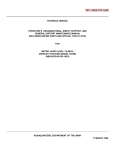
2-11. The 8922A controls, indicators, and connectors
are shown in Figure 2-2 and described in Table 2:-1.
Locate each feature on your DMM as you read the
description.
2-1
8922A
12
13 .
14
15
4
3
2
16
10
11
-,
9
18
17
'
5
l
/
0
I
I
a
0
0
I
~
20
19
Figure 2-2. Controls, Indicators, and Connectors
2-2
6
8
7
8922A
Table 2-1. Controls, Indicators, and Connectors (cont)
NAME
FUNCTION
INPUT
A BNC input connector. The low side is isolated from
power ground through a pair of parallel diodes.
2
Analog Panel Meter
Uncalibrated panel meter provides analog tracking of input
level; useful for peaking and nulling indications.
3
Digital Display
LED display provides a direct readout of the input signal
level; includes decimal point and polarity.
4
Annuniciators
LED's that light to indicate the selected measurement
function V (volts). mV (millivolts) or dB (decibels).
5
UN CAL
kl LED that light to indicate that the instrument's internal
protection circuitry is energized, see Crest Factor, under
operating instructions.
6
RELATIVE REFERENCE
kl LED that lights to indicate that the voltmeter is in the
dB display mode and using a relative voltage reference.
7
2/20/200/700
Indicate DMM range by decimal point locations.
8
POWER Switch
A push-push switch used to turn the instrument ON (in) and
OFF (out).
9
dBm REFERENCE
Rotary switch used to manually select 1-of-12 reference
impedances when the dBm and dB display modes are selected.
10
REL/dBm
A push-push switch used to select either the relative dB or the
dBm display mode. When REL is depressed, the existing input
level is used to establish a 0 dB reference. Subsequent level
changes at the input are displayed in dB and referenced to
the operator established 0 dB level. When dBm is selected,
measurements are displayed in terms of dBm and the dBm
REFERENCE setting.
11
dB/VOLTS
A push-push switch used to select either the voltage (out) or
dB (in) display mode.
12
STEP UP
A momentary pushbutton switch used to incrementally step
the voltmeter to its higher range. This switch is enabled only
when the HOLD RANGE mode is selected.
13
HOLD/AUTO
A push-push switch used to select the manual (HOLD) or
autorange (AUTO) mode. Selecting HOLD (in) enables
manual upranging with the STEP UP switch. Selecting AUTO
(out) enables the unit to autorange.
14
FILTER
A push-push switch which, when depressed, engages a single
pole filter to reject unwanted high frequency signals. See the
Specifications table for effect on accuracy.
15
AC/AC+ DC
(damping)
A push-push switch used to include (in) or delete (out) de
components as part of the input signal level. When AC + DC
is selected (in) damping increases which extends low frequency
operation down to 2 Hz. Reading and ranging rates are slower.
16
F1
Line fuse, MDL 1/8A slo-blo ..( 5 x 20 mm, 1/SA, slow acting for metric.)
REF
NO.
2-3
8922A
Table 2-1. Controls, Indicators, and Connectors (cont)
REF.
NO.
NAME
FUNCTION
17
DIGITAL OUTPUT/
LOG-ANALOG OUTPUT
An output port reserved for use with the Logarithmic
Output Option-004-521 Option, or the -529 IEEE Interface
Option, see Section 6 for details.
18
COUNTER OUTPUT
An output port reserved for use with the Counter Output
Option ~003. See Section 6 for details.
19
Linear Analog
A pair of banana jacks for output accessing the de linear
analog output voltage. This voltage is proportional to the V
rms input and is linearly scaled; 2V de out equals a 2000
count readout. The scale repeats for each range.
20
Input Power Connector
A 3-prong line power connector for connecting the unit to
line power.
2-12.
OPERATING NOTES
2-13. The following paragraphs describe various
conditions which you should be aware of before
attempting to operate the 8922A.
2-14.
2-20. The uncalibrated analog panel meter
complements the digital display by linearly tracking the
input signal level. It provides a O-to-100%-of-scale
indication for the selected range. This feature will aid you
in detecting the peak and null points of inputs having
varying levels.
Fuse Replacement
2-21.
2-15. The Model 8922A is fuse protected from the
power line. You can access the fuse by pressing and
turning (CCW) the fuse cap located on the rear panel.
When replacement is necessary use an MDL type 1/8 amp
slo-blo fuse for all voltage configurations. (For metric
fuse, use 1/SA, slow acting, 5 x 20 mm glass tube type.)
2-16.
Display Indications
2-17. In addition to the standard digital readout, we
have equipped the front panel display with a series of
unique visual indicators. These include an
overrange/ overload indication, an underrange
indication, and an analog meter. They function
automatically to help you make error free measurements.
2-18. For example, when an input signal level exceeds
the display limit for the selected range an overrange will
occur. The display digits flash while the overrange is
present. Selecting a higher range will eliminate the
overrange condition.
2-19. Measurement accuracy is uncertain when the
higher voltage ranges are used to measure low level
signals. To alert you to this condition, the decimal point
will flash when the input is too low for the selected range
(less than 180 digits). You may eliminate this underrange
, indication by manually selecting a lower range or
selecting autorange.
2-4
2-22.
Measurement Connections
COAX OR OPEN LEADS
2-23. We recommend that shielded or coax leads be
used at the input for low level or high frequency
measurements. Open leads (unshielded) may pick up
interference from other sources causing errors at low
levels. You may reduce high frequency errors by
minimizing inductance and capacitance between the
source and the 8922A input connector.
2-24.
SAFETY CONSIDERATIONS
2-25. Under normal operating conditions, the 8922A
will not present a potential electrical shock hazard to the
operator. However, careless use of input-lead connectors
and/ or adapters may create a shock hazard.
2-26. The low input on the 8922A is connected to power
ground through a pair of diodes (see front panel
connector). These diodes allow the low input terminal to
float up to 400 mV rms. Their function is twofold; they
provide isolation between input low and power ground,
and they protect the operator from the possibility of
hazardous voltages existing on the exposed low input
connector.
2-27. At first glance, 400 mV of isolation does not
appear significant. However, in most cases it provides
8922A
COMMON MODE VOLTAGE
MEASUREME NTS
enough isolation to prevent ground loop currents and,
therefore, measurement errors due to ground loops.
2-34.
2-28. When you connect the low input of the 8922A to a
potential greater than 400 mV above power ground, the
diode pair conducts and effectively clamps the input
common mode voltage.
2-3S. The 8922A will accomodate common mode
voltages as high as 600 m V peak, usually enough to
eliminate ground loops in the power connections. Higher
common mode voltages will be clamped to 600 mV up to a
2S amp maximum load capability.
WARNING
son MATCHING
POWER SPLITTER
TO AVOID ELECTRICAL SHOCK HAZARD
DO NOT REMOVE OR OTHERWISE DEFEAT
THE INPUT DIODE PAIR.
50n
RF
SOURCE
2-29. Under no circumstances should you attempt to
defeat the function of the diodes. Specifically, the diodes
should not be removed, the ground return on the power
cord should not be floated, and an isolation transformer
should not be used to power the 8922A. If the diodes are
defeated, a shock hazard will exist at the low input
connector when the low input lead is floated above 30
volts.
2-30.
8920A
WITH
50n IN
50n TERMINATION
(A)
IMPEDANCE MATCHING
50n
RF
SOURCE
2-31. Two types of ac voltage measurements are
typically made; those involving matched impedance
systems and those where voltmeter loading is minimized
(high impedance measurements) and no impedance
matching occurs.
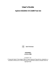
2-32. When matched impedance systems are measured,
the input cable should be terminated as close as possible
to the 8922A input, thereby minimizing input capacitance
and enhancing accuracy at high frequencies. This is
accomplished by including the meter as an integral part of.
the circuit as shown in Figure 2-3A. Notice that the
integrity of the son system is maintained by using a son
broadband matching power splitter. An alternate
solution is shown in Figure 2-3B. In this case, the source is
alternately connected to the 8922A and the test circuit.
This allows the source to be adjusted to a known level
before being connected to the test circuit. Since both the
meter and the test circuit are son loads the circuit
integrity is maintained. In either method, the accuracy
will be determined in part by the accuracy of the source
impedance and the accuracy of the termination.
son COAX
')
I
L
5on
TEST
CIRCUIT
8920A
WITH
son IN
50n TERMINATION
( B)
Figure 2-3. Matched Impedance Measurement Techniques
2-36.
Input Signal Considerations
2-37. The 8922A is a true rms voltmeter, and as such, is
subject to input conditions not encountered with the
ordinary average-reading ac voltmeter. Of these, the two
most important are crest factor and input coupling.
2-38.
2-33. High impedance measurements are based on the
assumption that the voltmeter's fixed 10 Mn input
resistance and low input capacitance will not appreciably
load or otherwise affect the circuit being measured. If the
measurement frequency is low, this assumption holds
true.
son
TEST
CIRCUIT
50n
CREST FACTOR
2-39. Cres·t factor is the ratio of the peak voltage to the
rms voltage with the de component removed. Above 10
Hz, the crest factor is limited by the dynamic range of the
amplifiers. Crest factor capability in this frequency range
will be at least 7 for full-scale inputs and will increase
2-5
8922A
proportionally as the input goes down-scale. Use the
following formula to calculate the crest factor of signals
less than full-scale:
7 (Range)
Input Level
For example, given the DMM is at the 20V range with a
lOV input:
required for good performance below IO Hz. This
additional damping may also aid in the measurement of
higher frequency signals when the level of the signal
fluctuates.
Crest Factor -
_ > (20V) _
Crest Factor -
140V _
lOV - 14
lOV
2-40 Below 10 Hz, crest factor is limited by the time
required for the internal rms sensor protection circuit to
energize and limit the sensor temperture. Typical low
frequency crest factor limitation is shown in Figure 2-4.
When the protection circuit does not energize, the
UNCAL annunciator will light indicating that the protection circuit is introducing measurement errors. When
this occurs, manually selecting a higher range may
produce a better measurement.
2-41.
a: 20
0
I(.)
<(
Ll..
15
1/2 SCALE
...
a:
,- I
(.)
3/4 SCALE
w 10
...J
al
<(
fh
en
2
a:
w
FULL-SCALE
5
a..
2-44. Seven voltage ranges, and what appears to be a
single dB range spanning 132 dB are provided in the
instrument. Range selection is normally accomplished
automatically. Override switches, however, allow you to
interrupt the autorange function and manually increment
the range...
2-45. The autorange function optlmIZes the display
reading for a given input. Each reading is displayed
complete with decimal point and units' annunciator. The
individual ranges are directly defined for the operator by
labeled decimal points. Underrange (flashing decimal
point) and overrange (flashing digits) indications are
provided to indicate when a range change is necessary.
2-46.
INPUT COUPLING, AC/DC
2-42. The 8922A is equipped with a FUNCTION switch
which allows you to select either AC or AC + DC
coupling. When the switch is out, AC coupling is selected.
In this function the de component is removed from the
input signal and is not measured or displayed. Depressing
the FUNCTION switch selects AC+ DC coupling. This
function allows the 8922A to measure and display the true
rms value for the total input signal; ac components and de
components. You should always consider the de
component when power dissipation is being determined.
·This function also increases the damping which is
Ien
w
2-43. Range Selection
AUTORANGE
2-47. The proper measurement range is automatically
selected when the HOLD/ AUTO switch is in the AUTO
(out) position. Both decimal point and units' annunciator
change automatically with range.
2-48.
MANUAL
2-49. Manual range determination is accomplished by
selecting a range using the autorange mode and then
depressing the HOLD/ AUTO switch. The meter will stay
in that range regardless of in put level changes. If the range
becomes invalid for a given input level, an overrange or
underrange indication will flash. If an underrange is
indicated, select autorange (AUTO). After the proper
range is selected, press HOLD. For overrange conditions,
momentarily press the STEP UP switch once for each
desired range increment. Holding the switch in will
increment the meter to the 700V range. Select autorange
(AUTO) to downrange.
2-50. Voltage Display Mode
2-51. The 8922A will display a voltage input in one-oftwo measurement units; volts or dB. To display the input
voltage in units of volts, you must set the dB/VOLTS
switch to VOLTS. The instrument will now display all
input in units of volts or millivolts, as indicated by the
front panel annunciators (V), (mV).
I
2
5
10
FREQUENCY (Hz)
Figure 2-4. Typical 8922A Crest Factor Limitation
2-6
2-52. Two points of interest about the volts display
mode are as follows: one, if the input is completely
unknown, allow the autoranging circuit to select the
appropriate range. Two, the selection of the volts display
8922A
mode will not affect any previous reference established in
the dB display mode (see following paragraphs for
additional information about establishing a dB
reference).
NOTE
The dBm REFERENCE switch does not
affect the fixed JO MO input impedance ofthe
8922A. All impedance matching terminations
must be added externally by the operator.
dB Display Mode
2-53.
2-54. When the instrument is in its dB display mode, all
voltage inputs are referenced to a selected level, and
displayed as deviations (in dB) above or below that level.
If you wish to display the input voltage in dB units, set the
dB/VOLTS switch to dB. The instrument's front panel
dB annunciator will now light, indicating to you that the
display is presenting a measurement in dB units.
2-55. The instrument references all inputs to a selected
level. Before a meaningful measurement in dB units can
be made, the desired reference level (0 dB) must be
established. See RELATIVE REFERENCE Selection
and dBm REFERENCE.
dBm Measurements
2-56.
2-57. Measurements made to a fixed l milliwatt
reference are defined as dBm. The 1 milliwatt reference is
generally assumed, as indicated by m. However, the
system impedance must be specified for a particular
measurement. Once the impedance is selected, the
instrument will display its measurements in dBm.
2-62. This feature allows you to make any voltage input
a "O dB point" to which all other voltage inputs may be
referenced. For measurements at a single test point, press
the dB switch, then the REL switch and watch the dB
change as you make adjustments or circuit changes.
2-63. A typical application for the dB measurement
mode is shown in Figure 2-5. The relative reference (0 dB)
has been established at TP2. Subsequent dB
measurements at TPl, TP3, TP4, and TP5 are displayed
(in dB) as shown.
2-65. Use the following procedure to enable the relative
(REL) display mode and select a relative (0 dB) reference.
l. Connect the reference source to the 8922A
input terminals. If desired, measure and adjust the
reference supply voltage level.
dBm REFERENCE SELECTION
2-60. Use the following procedure to select a reference
impedance and enable the dBm display mode:
l.
Depress the dB/VOLTS switch (in).
2.
Release the REL/dBm switch (out).
3. Set the dBm REFERENCE (0) switch to
correspond with the system impedance.
2.
Select the autorange mode (AUTO).
3.
Release the REL/dBm switch (out).
4.
Depress the dB/VOLTS switch (in).
5. With the reference level still connected to the
input terminals, depress the REL switch. The
display should now read 0 dB and the RELATIVE
REFERENCE annunciator should be lit.
NOTE
2-59.
RELATIVE REFERENCE SELECTION
2-64.
2-58. The 8922A is equipped with a rotary switch called
dBm REFERENCE (0). By setting the switch to l-of-12
possible standard reference impedances (500, 750, 930,
1100, 1240, 1350, 1500, 3000, 6000, 9000, 10000, and
12000) you establish that impedance as a reference.
When the system impedance and the reference are the
same, the display is in terms of dBm.
If the 1000 ohm reference impedance is
selected (''dBV" on the rotary switch), the 0 dB
point will correspond to 1 V.
Relative Measurements (REL)
2-61.
2-66.
OTHER dBm REFERENCES
2-67. When a dBm reference, other than those given on
the dBm REFERENCE switch is required, use the
following procedure to establish the reference:
1. Define the reference impedance (R) and
calculate V using the following formula:
V = 0.001 x R
2. Apply an adjustable voltage source to the
8922A input and set the dB/VOLTS switch to the
VOLTS position. Adjust the voltage source for a
display reading equal to the calculated value of V.
2-7
8922A
TP2
1. Measure 1 V
2. Press dB then rel buttons
3. 1 V becomes 0 dB reference
TP1
-60dB
-
,,
~
TP1
--
TP2
TP3
-2.5dB
TP3
~
TP4
+14 dB
TP4
--
TP5
+6dB
TP5
Figure 2-5. Typical Relative dB Measurements
3.
Depress the dB/VOLTS switch (in).
4. Depress the REL/ dBm switch (in). This
establishes the voltage (V) as the 0 dB reference
level. Therefore, subsequent dB measurements will
be equivalent to dBm measurements as long as the
system impedance R is maintained.
NOTE
This reference will hold as long as the
REL/ dBm switch is at the in position and the
instrument is energized.
2-68.
Linear Analog Output
2-69. A pair of banana jacks on the rear panel of the
8922A provides access to a linear de analog output signal.
This signal is proportional to the applied input signal and
is linearly scaled; a 2V de output is equal to 2000 counts
on the display. Output accuracy is ±I% relative to the
front panel reading. The output signal is buffered, and is
suitable for driving an external analog meter, recorder,
plotter, scope, etc.
2-70.
OPERATION
2-71. With reference to the preceding paragraphs, use
the following procedure to turn-on and operate the
2-8
Model 8922A (refer to Section 6 for option and accessory
information):
l. Connect the 8922A to line power.
2. Set the front panel POWER switch to ON (in).
The front panel display should light.
3. Select the appropriate input leads and connect
them to the meter's input terminals. Add
terminations as close as possible to the input
connector, if impedance matching is required.
4. Select input coupling by setting the
FUNCTION switch to AC (out) or AC+ DC (in),
as desired.
5. Select the desired range. Use automatic or
manual method, as desired.
6. Set the DISPLAY switches to select the desired
measurement mode: volts, dB, or dBm. If dB is
selected, establish a 0 dB reference.
7. Observing safety considerations, connect the
test leads to the measurement points. The results are
displayed on the 8922A readout.
8922A
Section 3
Theory of Operation
3-1.
3-5.
INTRODUCTION
3-2. The information in this section describes the theory
of operation for the 8922A True RMS Voltmeter. The
theory has been divided into two major headings; overall
functional description and detailed block diagram
description. To gain maximum benefit from this section,
we recommend that you read each paragraph in the order
presented while referring to the associated figure or the
appropriate schematic in Section 8.
3-3.
OVERALL FUNCTIONAL DESCRIPTION
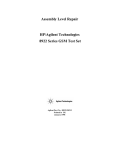
3-4. As you can see in Figure 3-1, the circuitry of the
8922A can be divided into two sections; analog and
digital. An overall functional description of these two
sections is presented in the following paragraphs.
Analog Circuitry
3-6. The analog section comprises the largest portion of
the 8922A circuitry. As shown in Figure 3-1, this section is
broken down into the following areas: the signal
conditioner, the rms converter and the power supply.
3-7. Referring to Figure 3-2, you can see that the signal
being measured by the 8922A can be coupled to the signal
conditioner in one of two ways (AC or AC+ DC). When
you place the FUNCTION switch on the front panel to
the AC position all input signals are capacitively coupled;
when the AC + DC position is selected the input signal is
de, or directly coupled. This feature contributes to the
measurement accuracy when de components are present
in the input signal.
LINEAR ANALOG
OUTPUT (8920A only)
,---
ANALOG CIRCUITRY
INPUT
HI
+5V
SIGNAL
CONDITIONER
RMS
CONVERTER
+15V
-15V
INPUT
LO
- ----=-~-i
POWER
SUPPLY
I
I
_J
- - - - - - - ---____._______,
- -CIRCUITRY
IDIGITAL
I
A/D
I DISPLAY
CONTROLLER ---i CONVERTER
I
I
_______ _ J
L----Figure 3-1. Overall Block Diagram
3-1
(.)
co
I
co
I\)
I\)
I\)
)>
f'SIGNAL CONDITIONER -
I
~
I
>---+
0
-
-
-:-1.1,-d11,
+11000
X5, X2.6,
X26
RANGE
INFORMATION
RANGE
I
INFORMATION(
~
3
I
INPUT POWER
115/220V
50- 400 Hz
POWER
SUPPLY
I
I
I
I
I
OUTPUT
f"RMS CONVERTER -
I I
I I
..
-
-
DECODER
I"' I
I
I
I
I
I
I
I I
I I PRO;~TION
I
I AUTO RANGE
ENCODING
I
I
I
I
I I
I I
II
II
CONTROLLER ...
I
I
RMS SENSOR
XL!
-----,
_J
I
REFERENCE
INPUT
INT
DE
ICM
I
A/D
... CONVERTER
AZ
STROBE
DRIVERS
I I
::
ANNUNCIATORS
I
I DISPLAY & ANNUNCIATOR
1
-----,
>----e--'--:...t~
RANGE TNFoR'MATioN-
CLOCK
+5V +15V -15V
-
_____ _ JL _____ _
IX1
~
-
FEEDBACK
NETWORK
L_
i.
g
-
-
INTERMEDIATE
ATTENUATOR
+1, +10
a:
0
iii'
-
1V RMS
FULL-SCALE
A~TEN~ATOR
'Tl
~
-
FEEDBACK
NETWORK
~·
CD
-
INPUT
IN-LO
..
-
L--------
~NTROLLER_
DATA
OUTPUT
OPTION
_ _ _J
I
_J
FRONT PANEL
SWITCHES
I
AUTOZERO
I
~DCONVERTER _ _ _ _
I
J
8922A
3-8. The signal conditioner insures that the varying
levels of instrument input voltages are properly scaled
before being applied to the rms converter. The rms
converter works on a thermal sensing principle. Basically,
it operates by balancing the heating power of a de
feedback signal to the heating power of the ac input
signal. When the two are equal, the circuit is in
equilibrium and the de output voltage applied to the A/ D
converter is directly representative of the true rms value of
the ac input signal. The de output of the rms converter is
also applied to the LINEAR ANALOG OUTPUT
terminals on the rear panel of the 8922A, as well as the
analog meter on the front panel of the 8922A.
representation is processed by the controller to obtain a
bed output which is proportional to the selected display
mode (VOLTS, dB, dBm, REL). The BCD output is
decoded and applied to the display.
3-9. The last analog circuit we discuss in this section is
the power supply. This circuit provides three regulated
power supplies (+5V, +I5V and -15V) to operate the
instrument.
3-15.
3-10.
Digital Circuitry
3-11. The digital circuitry comprises the A/ D converter,
the controller, and the display. Together these circuits
develop a digital representation of the rms value of the
input signal, produce the commands that set the range
and function of the instrument, and finally display the
input value.
3-12. The de output of the rms converter is translated to
a digital representation by the A/ D converter. The digital
I
DETAILED BLOCK DIAGRAM
DESCRIPTION
3-14. In the following paragraphs we discuss, in detail,
the individual functions within the major areas of
circuitry in the 8922A. Each major circuit area is detailed
in Figure 3-2. The description for each circuit is keyed to a
separate block diagram, or to the schematics in Section 8.
Signal Conditioner
3-16. The signal conditioner utilizes an input
attenuator, two amplifiers (Amp A and B) and the
intermediate attenuator. As shown in Figure 3-3, these
circuits are used to scale the varying voltage levels applied
to the instrument so that the input to the rms converter is
always between 0.09V rms and IV rms. The diagram in
Figure 3-3, illustrates the configuration of the circuitry
within the signal conditioner. The controller, through a
range decoder network, issues commands which select the
appropriate division factor in the attenuators and the
correct multiplication factor for amplifier A. Table 3-1,
lists each operating range and the corresponding division
and multiplication factors for the attenuators and
amplifier (note that amplifier B has a fixed gain ofX21).
------------,
r
UNKNOWN
INPUT
180 uV TO
700V AC
3-13.
INPUT
+
ATTENUATOR
+1.1, 110 or 11000
INTERMEDIATE
ATTENUATOR
11V RMS
+
FULL SCALE
>-----RMS
SENSOR
X2.6 or 26
FIXED
ATX2
I
RANGE COMMANDS
L ____ _
I
I
I
SIGNAL CONDITIONER_J
----RANGE
DECODER
FRONT PANEL--~ CONTROLLER
STEP COMMAND
Figure 3-3. Signal Conditioner
3-3
8922A
Table 3-1.
INPUT
ATTENUATOR
RANGE
Signal Conditioner Gain Configuration
*CONDUCTING
COMPONENTS
INTERMEDIATE
ATTENUATOR
AMPA
2mV
+1.1
X26
+1
K1, 06, 028, 032
20mV
+1.1
X2.6
+1
K1, 06, 029, 032, 057
200 mV
+1.1
X2.6
+10
K1, 06, 029, 031, 057
2V
+110
X2.6
+1
K2,Q3,Q5,Q29,032,Q57
20V
+110
X2.6
+10
K2, 03, 05, 029, 031, 057
200V
+11,000
X2.6
+1
K2,Q4,Q5,Q29,032,Q57
700V
+11,000
X2.6
+10
K2,04,05,Q29,031,057
*Refer to the schematics in Section 8.
I
I
The last column lists the component's FETs and relays,
that conduct to establish gain configuration of the circuits
(see the schematics for details on components).
3-17.
RMS Converter
3-18. The ~922A uses a thermal rms converter circuit
which supplies a de output voltage proportional to the
rms value of the ac input. The thermal sensor is a pair of
resistor-transistor elements thermally isolated from each
other and the case (see Figure 3-4). The ac input signal
(Vac from amp B) produces a temperature change in the
rms sensor's input resistor which is sensed by the
associated transistor and causes a voltage change at the
negative input of the integrator. Feedback, through the
square root amplifier, provides a de voltage to the rms
sensor's output resistor so that a similar temperature rise
occurs in the output resistor. The sensor gain is not
constant with changes in input amplitude. These changes
in gain are compensated for by the square root amplifier
to maintain a constant response time for level changes.
+15V +15V
r
INTEGRATOR
I
.
l
SQUARE ROOT
AMP
I
=i1
E.
INPUT FROM
'iAMP-A
I
I
I
a:
(/)a
2: (/)
a:Z
I
~I
AMPB
FEEDBACK
NETWORK
jx21 GAIN_
I
-15V
Figure 3-4. RMS Converter
3-4
_J
E0
i
1V de
FULL SCALE
OUTPUT
TOA/D
.CONVERTER
8922A
3-19. The rms sensor is susceptible to damage from
overvoltage inputs. During an overload condition, the
protection circuit will clamp the output of Amplifier B to
prevent damage to the sensor. Overload conditions would
result during turn on, turn off, or any time therms value
of the applied input exceeds the operating range of the
sensor.
3-20.
A/D Converter
3-21. A dual-slope integration A/ D conversion
technique is used in the Model 8922A. This method
applies the unknown voltage to a capacitor and allows the
capacitor to charge for a specific time interval. At the end
of this interval, the unknown voltage is removed (the
charge on the capacitor at this time will be proportional to
the level of the unknown voltage). Then a known voltage
of opposite polarity is applied to the capacitor, and clock
pulses are counted while the capacitor discharges. When
the capacitor has reached its original charge point, the
number of clock pulses counted is a digital construct of
the analog voltage input to the A/D converter.
3-22. For the following discussion refer to Figure 3-5,
the A/ D Converter Simplified Schematic and Timing
Diagram, and Figure 3-6, Controller Timing (A/D
Converter).
3-23. At the beginning of the measurement cycle, INT
goes high and the de output of therms sensor is applied to
the A/ D integrator for 100 msec. Capacitor, C203,
charges up from the auto zero level at a rate proportional
to the applied input voltage and the comparator's output,
CM, is driven low. At the end of the 100 msec integrate
period, DE H goes high, applying the reference voltage
to the integrator. The integrator then discharges at a rate
which is constant for all on scale inputs and the controller
begins counting clock pulses. When C203 has discharged
to the auto zero level, CM will go high, the controller will
stop counting and the reading is displayed. This starts the
auto zero period which allows the A/ D converter
circuitry to settle before the next cycle begins. If CM has
not occurred before the end of the 200 msec maximum
DE(-) period, the input will have exceeded the present
range. In this case, the DE period will continue until
either CM or the end of the 100 msec AZI occurs. When
the AC + DC function is selected, all timing increase
approximately 2.5 times.
3-24.
Controller
3-25. The controller is a custom LSI that controls
autoranging, the A/D converter, the display, and
annunciators. In addition, the Controller can count in a
non-linear (dB) scale and display its count in dB units. A
summarized description of each input and output pin
used on the controller is give in Table 3-2 and shown in
Figure 3-7.
3-26.
AUTORANGING
3-27. Autoranging is the automatic selection of the
instrument's range by the controller. With the low range
enabled, the instrument may range through seven voltage
ranges from 2 mV to 700V rms. Autoranging also applies
in the dB modes but gives the effect of a single range
spanning 132 dB. By coding the logic levels on the three
lines, FO, Fl, and F2, the controller selects a range (see
Table 3-3, Output Range Codes) by setting up the circuit
conditions of the input and intermediate attenuators and
amplifier A that are necessary for signal conditioning in
that range. (See Table 3-1, Signal Conditioner Gain
Configuration.) If the controller senses that the input is
above or below the selected range (see Table 3-4,
Over/ Underload Conditions), it shifts up or down one
range (depending upon the direction sensed) and halves
its cycle time. The controller blanks the display and
determines whether the input to the instrument is now in
range or if a further change in range is necessary. When
the proper range is found, display blanking is removed
and the cycle time returns to normal. Use of the HOLD
RANGE control will command the Controller to remain
at the present range (see Table 3-5, Input Range Codes)
via command input line D, E, and F. A signal from the
STEP UP RANGE control will increment the instrument
one range.
3-28.
COMPUTATIONS
3-29. The controller is able to count (compute) in two
modes, linear or non-linear. The following paragraphs
will explain how the controller obtains its linear (volts) or
non-linear (dB) readings.
3-30.
Voltage Computations
3-31. To make a voltage measurement the controller
must linearly count clock pulses for a time determined by
the A/ D converter. Referring to Figure 3-7, you can see
that when the dB/VOLTS switch is placed in its up (out)
position the rate multiplier (RM) will be shunted and the
main counter will count the number of clock pulses
exactly as they occur (linear). As soon as the integrator in
the A/ D converter reaches the auto-zero point, CM will
go high, commanding the main counter to stop counting
and start shifting its count to the data latches. A count of
clock pulses, in BCD format, that is proportional to the
true rms value of the signal being measured. The BCD
data is then shifted out of the controller, to a sevensegment decoder on four lines: W, X, Y and Z.
3-5
8922A
INTEGRATOR
COMPARATOR
RMS
CONVERTER
REF.
VOLTAGE
INT
DE
INT
AZ
CM
CONTROLLER
AUTO ZERO
PERIOD
INTEGRATE
PERIOD
IUNDER RANGE
INT--!
CLOCK I I I
I
I
I
100 mSEC
'
I I I I I I I
I
I
I
I
1I I I I I I
I I I I I I
11 I 1 I I I I I I I II I I
1
~ .
I
I
DE------rl
:
I
I
I
I
I I
I I
DE------11
:
!
. ._,......-----
I
I
AZ
c:CM
~
CM---.
1
I
I :
DE _ _ _ _ _ _ _ _
CM--
:,
o
1
200 mSEC MAX
I
180
1
I
-1-------
,,..
lr--j--1999
For AC+ DC (damping) Function, times increase by 2.5.
Figure 3-5. A/D Converter Simplified Schematic and Timing
3-6
-
. 8922A
20a-ms
EXTENDED
OVERLOAD (OL)
AUTO - ZERO
1aa ms
INTEGRATE
'
1
a
0 9
a9
0 9
a9
OL ONLY
NOTE:
If AC+ DC (damping) is
selected, all times increase
by 2.5.
Dl,
55 us
B
2aa us DE
(REFERENCE)
CM
OL
CM
1aa ms
AUTO ZERO
OR
AZ 1
Figure 3-6. Controller Timing (A/D Converter)
Table 3-2. Controller Summary
INPUT/
OUTPUT
PIN DESCRIPTION
PIN#
PIN NAME
Input
1
Vss
+5V supply
Input
2
CM
Compare signal from A/D Converter.
Input
3
CL1
External Oscillator input.
Input
4
CL2
4aa kHz crystal input for internal oscillator.
-
RG
Negative going pulse in the middle of each strobe. Insures
strobed data for DOU is valid.
6-1 a,
12-14
STa-ST7
Eight strobes that indicate which LED is to be enabled and
accept the data on lines W, X, Y and Z.
Input
11
RD
Impedance reference selection line, in dB.
Output
15-17
Fo-F 2
Output
5
Output
Encoded range lines, Fa= MSB, F 2 = LSB, code equals range
# + 1, voltage swings from; -15 to av.
Input
18
(3
Strobe input on this pin determines the lower range limit.
Input
19
a
Strobe input on this pin determines the upper range limit.
Output
20
DP
Enables display decimal point.
Input
21
Voo
Ground, OV supply.
3-7
8922A
Table 3-2. Controller Summary (cont)
INPUT/
OUTPUT
PIN#
Output
22
BZ
Indicates new data is ready for DOU, occurs after CM, one
strobe raster long.
Input
23-25
F, E & D
Enables controller ranging, see Table 3-5.
Output
26-29
W,X, Y&Z
BCD data, W = MSB, Z = LSB, TTL compatible.
Output
PIN NAME
BLK
30
Input
31
Input
Input
PIN DESCRIPTION
Drives blanking input on display decoder driver, TTL compatible.
-
K
700V range overload enable.
32
VGG
-15V supply.
33
J
Enables 311:.i or 411:.i digit display in linear mode and determines (in
combination with RD) the fixed reference in dB mode.
Input
34
T1
Test (not used).
Input
35
dB
Enables dB display mode.
Output
36
INT
Enables not integrate period of AID Converter.
Output
37
INT
Enables integrate period of AID Converter.
Output
'
38
AZ
Enables auto zero period of AID Converter.
Output
39
DE (-R)
Enables integrate reference period for positive input of
AID Converter.
Output
40
DE (+R)
Enables integrate reference period for negative input of
AID Converter (not used).
Q..[QLTS
0
LINEAR
OdB
r"'
JUUll
NON LINEAR
~
--------,
RM
12000
40
39
38
37
36
35
34
33
32
31
30
29
28
27
26
25
24
23
22
21
+5V 1
I NT -------1
I NT--+----1
AZ - - . - - - - l
DE (+Rl-------1
DATA
LATCHES
A/D
CONTROL
DE (-R)--+----l
'---r---'
CM-+----'
REFERENCE
LATCHES
RE~
~~
I
I
I
I
I
1,
! .:·~1~g: ~?:~~ I"' I !re
____---1-------.J
_____
0
L_\..._
"
___,)
y
FRONT PANEL COMMANDS
D,E & F
Figure 3-7. Controller Functions
3-8
CM 2
CL{ XTAL 1 3
XTAL2 4
AG 5
STO 6
ST1 7
ST2 8
ST3 9
ST4 10
RD 11
ST5 12
ST6 13
ST7 14
Fo 15
F1 16
F2 17
18
~
a 19
DP 20
8920 LSI
DE(+R)
DE(-R)
AZ
INT
INT
dB
I1
J
-15V
K
BLK
z
y
x
w
D
E
F
BZ
GNDOV
8922A
Table 3-3. Output Range Codes
3-32.
DATA LINES
RANGE
dB Computations
3-33. If the 'dB/VOLTS switch is in the dB position, a
non-linear count of the clock pulses is enabled. The
binary rate multiplier (RM) passes only a fraction of the
clock pulses on to the controller's main counter (see the
illustrated input to the main counter on Figure 3-7). This
count approximates the logarithmic curve of the dB scale
and, like the VOLTS mode, is stored in the data latches.
Fo
F1
F2
2mV
0
0
1
20mV
0
1
0
200 mV
0
1
1
2V
1
0
0
20V
1
0
1
3-34.
200V
1
1
0
700V
1
1
1
3-35. Don't let the m confuse you, it simply means that
the power level, as measured in "dB Computations", is
referenced to l mW. In other words, when the instrument
reads 0 dB the system being measured will be dissipating l
mW of power. The following will explain how the
controller obtains a measurement of power referenced to
l mW (dBm).
'
Table 3-4. Over/Underload Conditions
LINEAR
dB*
Overload:
>1999 (3
25.30 (20V range)
except for 700
700V range:
>700a
56.10
Underload:
<180
4.30 (20V range)
132
1.60 (20V range)
minimum input
for accurate dB
conversion
3-36. In order for the controller to obtain a
measurement in dBm, the appropriate reference
impedance must be used. A 1200 ohm reference
impedance is assumed by the RM. Therefore, if any other
reference is desired an· appropriate constant must be
added or subtracted from the count. The dBm
REFERENCE rotary switch connects one of the eight
strobes to RD and. J. The controller responds by sending
the appropriate constant to its ADD/SUB.
3-37. Referring to Figure 3-7, let's assume that a 600
ohm reference impedance is selected and the instrument
has previously made a relative measurement. Strobe zero
will be applied to RD until the REL/ dBm switch is placed
in its dBm position. At this time strobe 4 (corresponding
to 600 ohms) is applied to RD and causes the controller to
select the 600 ohm reference impedance data. This data
along with the range and polarity data is then shifted to
the ADD/SUB where it is combined with the count
referenced to 1200 ohms. The resultant value is now
equivalent to a dBm reading referenced to 600 ohms. The
range and polarity data is held in the reference latches
until RD or J detect a strobe change or unless the
instrument is turned off. (Switching to the VOLTS mode
will not cause the data in the reference latches to be lost.)
*dB calculations are based on a 1200 ohm reference
impedance and 20V range. The calculation is then
corrected for the proper range ~nd the selected
impedance by the addition of the appropriate
constant, which may be calculated from the
following equation:
20 logv'1.2-20 log v'o.001 R + N (20).
Where N = number of ranges above or below the
20V range, i.e., 2 mV range N = X4
Table 3-5. Input Range Codes
COMMAND LINES
D
E
F
8922A CONTROLLER
FUNCTION
0
0
1
Auto range fast range cycle
1
0
0
Hold present range (overridden
by a & (3)
1
1
0
Range up at CM time (over·
.ridden a & (3)
dBm Reference
3-38.
Relative (REL) Reference
3-39. Relative reference measurements allow any
voltage input to become the 0 dB point to which all
subsequent voltage inputs are referenced. The controller
makes a relative reference computation much the same
way it made a dBm computation. However, in the REL
mode, 0 dB no longer refers exclusively to l mW. The
following explains how the controller makes a relative
reference measurement.
I
3-40. Referring the Figure 3-7, you can see that upon
selection ofthe REL mode, the reference impedance data
line will be disabled. However, to make a relative
3-9
8922A
reference measurement the controller must use an initial
reading, and to obtain an initial reading it must use a
reference impedance. Therefore, before the REL mode
can be selected the controller must be allowed to make at
least one complete measurement while in the dBm mode.
Once the measurement has been completed the REL
mode may be selected. The reading will now be fed back
to the reference latches and held. The controller will
subtract the reading in the reference latches from all
subsequent readings. Note that if the instrument is ranged
up/ down, 20 dB will be added to or subtracted from the
reading held in the reference latches. The reading held in
the reference latches, however, will be lost any time the
instrument is turned off or if the REL switch is released.
3-41.
Display and Annunciators
3-42. The computed value of the input to the instrument
is transmitted serially as four-bit BCD characters on the
. W, X, Y, and Z data lines from the controller to the sevensegment-decoder, see Figure 3-8, Display and
Annunciators. The output of the seven-segment-decoder
drives the Display Data Bus, which is common to the
inputs ofall five of the display LEDs. Strobe pulses from
the controller determine which display LED is enabled to
accept the data on the Display Data Bus. ST4 through
ST7 strobes the seven-segment LEDs from LSD to MSD,
respectively. STO gates the ±1 digit. If the volts display
mode is selected, 3\,2 digits will be enabled resulting in a
resolution of0.05%. If the dB display mode is selected, 4Y2
digits will be enabled and the resolution will be 0.01 dB.
The decimal point is enabled separately by the DP line
from the controller.
3-43. the annunciators, excepting the UNCAL, are
strobed on by STO which is routed through two circuits.
One path is completed when the dB/VOLTS switch is in
the dB position. The dB annunciator DS309 is enabled. If
the REL/ dBm control is in the REL position, RELATIVE REFERENCE annunciator, DS308, will also be
enabled. If the dB/VOLTS switch is in the VOLTS
position, STO is routed through another path and either
the V annunciator, DS307, or the mV annunciator,
DS306, is enabled depending upon the current range of
the instrument.
3-44.
Power Supply
3-45. The power supply section on the Main PCB
provides the instrument with operating voltages of+ l 5V,
-15V, and +sv.
3-46. Line voltage (IOOV, 120V, 220V or 240V, as
selected by switches S209 and S210) is connected to the
primary of the main power transformer, T200 via
POWER switch, S208, and fuse, Fl. the secondary of
T200 contains two windings. One winding drives the +SV
power supply, the other drives the ±15V power supply.
3-47 In the +sv power supply, power from the
secondary winding is full-wave rectified by CR205,
filtered by C211, and regulated by VR203.
3-48. In the ±ISV power supply, power from the
secondary winding is full-wave rectified by CR204,
filtered by C209 and C2IO, and regulated to +15V by
VR202. The -15V is regulated by U21 l and Q207.
REF
CONTROL
8922A CONTROLLER
STO
DP
ST6
ST7
ST5
ST4
,
-,- II
I
I
I
I
,-,
,-,
,-,
,-,
,.,-, -·I -·I I
11
1-
11
1-
I
I -~l
11
1-
wx y z
·~-I
•
I
RD.J D,E,F,a,(l STO-ST7
dB/LIN
I
BUFFERS
----...
RANGE
CONTROL
I
FRONT PANEL
COMMANDS
OJ
C'l
0
0
(RANGE, REF, REL,
dBM,2 mV ENABLE)
)>
-I
+++ ~ +
)>
c::
z
ANNUNCIATORS
V. mV, dB,2 MHz,
REL
m
CJ)
,.,
I
11
1-
-Kl-
-
~
A
,,
'.
r
8
c
D
E
SEVEN
SEGMENT
DECODER
F
G
t
Figure 3-8. Display and Annunciators
3-10
•r
BLK
8922A
Section 4
Maintenance
WARNING
THESE SERVICING INSTRUCTIONS ARE FOR USE BY QUALIFIED PERSONNEL
ONLY. TO AVOID ELECTRIC SHOCK, DO NOT PERFORM ANY SERVICING OTHER
THAN THAT CONTAINED IN THE OPERATING INSTRUCTIONS UNLESS YOU ARE
QUALIFIED TO DO SO.
4-1.
INTRODUCTION
4-2. This section of the manual contains maintenance
information for the Model 8922A True RMS Voltmeter.
The material is presented under the categories of shipping
information, general maintenance, performance test,
calibration adjustments, and troubleshooting. The
performance test is recommended as an acceptance check
when the instrument is first received and as performance
. verification test at regular intervals. Table 4-1 lists the test
equipment required to calibrate your 8922A. If the
recommended equipment is not available, you may
substitute equivalent equipment that meets the required
characteristics.
4-3.
SERVICE INFORMATION
4-6.
GENERAL MAINTENANCE
4-7.
Access Information
4-8. To gain access to the interior of the instrument,
remove the four screws located on the bottom of the case.
The top cover can now be removed.
4-9.
INPUT POWER SELECTION
4-10. The 8922A may be operated from any one of the
line voltages shown in Table 4-2. Use the following
procedure to prepare the instrument for use with the local
line power.
4-4. The 8922A is warranted for a period of I year upon
delivery to the original purchaser. The warranty is located
on the back of the title page.
I. Disconnect the instrument from the line power
and remove its top cover (four screws on the bottom
of the unit hold the top cover in place).
4-5. Factory authorized calibration and service for your
8922A is available at various locations throughout the
world. A complete list of these factory authorized service
centers is included in Section 7. If requested, an estimate
will be provided to you before work is begun on an
instrument that is beyond the warranty period.
2. Set switches, S209 and S210, to the positions
indicated in Table 4-2 for the desired line voltage.
3. Install the top cover and connect the unit to line
power.
4-1
8922A
Table 4-1. Recommended Test Equipment
EQUIPMENT
NOMENCLATURE
REQUIREMENT
RECOMMENDED
EQUIPMENT
Precision AC Calibrator and
Power Amplifier
19 mV to 600V
20 Hz-50Hz, ±0.2%
50 Hz-50 kHz, ±0.1%
John Fluke 5200A
&
~ohn Fluke 5205A
DC Voltage Calibrator
±0.5% ±3 µ.V
(AC Component< 100 µ.V)
John Fluke 341A
Leveled Generator
Short term stability, drift
and adjustment resolution< .1%
Freq. range 50 kHz-11 MHz or
greater.
Tektronix SG-503/
Series 500 Mainframe
DVM
3Y:i digits, 0.25% Resolution
JF-8020A
Flat Attenuator, 20 dB
(three required)
Flatness
50 kHz-1 MHz, ±0.1%
50 kHz-10 MHz, ±0.5%
GR, 874-G20L
1V Transfer Standard
50 kHz-11 MHz, ±0.1%
JF-A55 1V
GR Tee
Adapter
Adapter
Adapter
874
874-BNC (2 required)
874-BNC
Banana-BNC
GR, 874-TL
GR, 874-QBPAL
GR, 874-QBJAL
Pomona 1296
Feed thru 50!1
Termination
1 GHz rated
TEK, 011-0049-01
RMS Voltmeter
2 Hz-10 Hz ±1%
JF-931
Function Generator
2 Hz Sine wave
Table 4-2. Input Power Selection
SWITCH POSITION
(REAR PANEL)
- - u
-a - S209
S210
IHI
IHJ
SELECTED LINE SOURCE
ac ±10%, 10 WATTS MAX
120V, 50-400 Hz
~
Ill]
DI
4-2
100V, 50-400 Hz
g
220V. 50-400 Hz
II!]
240V, 50-400 1-iz
(250V, MAX)
8922A
4-11.
Cleaning
CAUTION
Do not use aromatic hydrocarbons or
chlorinated solvents for cleaning. These
solutions will react with the plastic materials of
the instrument.
4-12. Clean the front panel and case with denatured
alcohol or a mild solution of detergent and water. Clean
-dust from the interior of the instrument with dry, low
pressure air (20 psi). Contaminants can be washed from
the circuit board with demineralized water and a soft
brush (avoid getting excessive amounts of water on the
switches).
4-13.
Fuse Replacement
Section 1 of this manual. The test is recommended as an
acceptance test when the instrument is first received and
later as a calibration procedure to verify instrument
accuracy at the scheduled calibration periods (90-days). It
can also be used as an aid in troubleshooting. Test
equipment required for the performance test is listed in
Table 4-1. If the recommended test equipment is not
available, equivalent test equipment may be substituted.
To insure optimum results, the test must be performed at
an ambient temperature between 18 and 28 degrees
Celsius with a relative humidity of 80%. Allow the
instrument to warmup at least 30 minutes, with the case
cover in place, before attempting the performance test.
4-17. If the instrument fails to meeet the performance
test limits, calibration adjustment, troubleshooting,
and/ or repairs are indicated. Procedures for calibration
adjustments and troubleshooting are given later in this
section of this manual.
4-14. The 8922A has one replaceable fuse located on the
rear panel which may be replaced with a l / 8 amp, slo-bl~
fuse (Metric uses 5x20 mm, l / 8 amp slow acting).
4-15.
NOTE
In all of the procedures in this section,
precautions should be taken to minimize
ground currents, stray fields, etc.
PERFORMANCE TEST
NOTE
4-18.
In the following procedures the instrument
(8922A) which is being either checked or
calibrated is referred to as the UUT (Unit
Under Test).
4-16. The following paragraphs comprise a
performance verification test which compares the
instrument's performance to the specifications given in
LINEAR
ANALOG
OUTPUT
Low and Midband Performance
Check (Volts Display Mode}
4-19. This procedure will verify tha~ the UUT's low and
midband performance is within the limits specified in
Section I. Set up the test equipment as shown in Figure
4-1, and select the required function and input signal as
indicated in Table 4-3. Note any deviation between the
UUT performance and the specified limits.
8922A (REAR)
DVM
(8600A)
SHIELDED
CABLE
POWER AMP
(5205)
\
8922A (FRONT)
NOTE:
WHEN TESTING THE 8922A A BANANA TO
BNC ADAPTER MUST BE USED (POMONA 1296)
Figure 4-1. Low and Midband Performance Test Set-Up
4-3
8922A
Table 4-3. Low and Midband Performance Checks (Volts Display Mode)
FUNCTION
MODE
INPUT
RANGE
LEVEL
F(Hz)
DISPLAY
LIMITS
or
COUNTS
COMMENTS
AC,
AUTO RANGE
2mV
1.9mV
500
1.000
±38
Note that the mV annunciator is lit.
AC,
AUTO RANGE
20mV
10mV
500
10.00
±10
Note that the mV annunciator is lit.
AC,
AUTO RANGE
200 mV
1.00 mV
500
100.0
±5
Note that the mV annunciator remains
lit.
AC, HOLD
2V
3V
500
1.999
AC, HOLD
2V
1V
500
±.01V
AC, HOLD
2V
. 2V
500
±.002V
AC, HOLD
2V
.17V
500
.17
AC,
AUTO RANGE
2V
1V
500
1.000
±5
Note that the V annunciator is lit.
AC,
AUTO RANGE
20V
10V
500
10.00
±5
Note that the V annunciator remains lit.
AC,
AUTO RANGE
200V
100V
500
100.0
±5
Note that the V annunciator remains lit.
AC,
AUTO RANGE
20mV
10 mV
50K
10.00
±10
Note that the UUT autoranges down to
the 20 mV range.
AC,
AUTORANGE
200mV
100mV
50K
100.0
±5
AC,
AUTO RANGE
2V
1V
50K
1.000
±5
AC,
AUTO RANGE
20V
10V
50K
10.00
±5
AC,
AUTO RANGE
200V
100V
50K
100.0
±5
AC,
AUTO RANGE
700V
600V
500
600
±3
Use the 5205A for this test.
AC,
AUTO RANGE
2V
1V
2 Hz
1.000
±50
(4to 7
digit
fluctuation)
Use rms voltmeter and function
generator.
4-4
Verify that display flashes 1.999
signifying overrange.
Measure 1V on the linear analog output.
Note that the test instrument's reading
is within ±.01 V of UUT's displayed
reading.
Measure 0.2V on linear analog output .
Note that the test instrument's reading is
within ±.002V of UUT's displayed reading.
Verify that decimal flashes signifying below
9% of range.
8922A
4-20.
4-24.
dB Display Mode Check
4-21. This procedure will verify that the UUT's dB
display mode is functioning properly. Set up the test
equipment as shown in Figure 4-l. Depress the RANGE
HOLD switch and step up to the 2V range. Select the 1V
range on the AC calibrator and adjust its output for 1.000
on the UUTs display. Select the dB display mode and
switch through the dBm REFERENCE selection switch,
checking the reading at each position against Table 4-4.
The readings should not differ by more than ± 1 digit from
the numbers given in Table 4-4.
4-22.
AC Low Level Check
4-25. This procedure will verify that the UUT's low level
AC performance meets the specifications of Section 1. Set
up the test equipment as shown in Figure 4-3 and
complete the AC Low Level Calibration procedure, but
replace steps 2-d and 2-e with the following:
d. Note that the UUT's display reads the same
error as noted in step 1-f ±38 digits.
e. Note that the UUT's display reads 0.1900 ±4
digits.
4-26.
DC Low Level Check
4-23. This procedure will verify correct operation with
low level DC inputs. Set up the test equipment as shown
in Figure 4-2, and select the required function, range and
input signal as indicated in Table 4-5. Note any deviation
between the display of the UUT and the specified limits.
High Frequency Response Check
4-27. This procedure will verify that the UUT's high
frequency response meets the specifications of Section I.
Set up the test equipment as shown in Figure 4-4, and
select the required input amplitude and frequency as
indicated in Table 4-6. Note any discrepancies between
the display reading and the limits given.
Table 4-4. dB Display Mode Check
MODE
REFERENCE
OHM
SOURCE
DISPLAY
READING
COMMENTS
dBm
50
1.000
+13.00
dBm
75
1.000
+11.24
dBm
93
1.000
+10.31
dBm
110
1.000
+9.58
dBm
124
1.000
+9.06
dBm
135
1.000
+8.69
dBm
150
1.000
+8.23
dBm
300
1.000
+5.22
dBm
600
1.000
+2.21
dBm
900
1.000
+ .45
dBm
1000
1.000
- .01
dBm
1200
1.000
-
REL
1.000
+0.00
Note that the dB and REL annunciators
are lit.
REL
10.00
+20.00
Step up to the 20V range (note that the
dB and REL annunciators remain lit).
Note that the dB annunciator is lit.
.80
4-5
8922A
SHIELDED
CABLE
DC CALIBRATOR
(341A)
8922A
Figure 4-2. DC Low Level Check
Table 4-5. DC Low Level Check
DC INPUT
RANGE
FUNCTION
UUTDISPLAY
±6COUNTS
COMMENT
1V
2V
AC+DC
1.000 ±30 counts
UUT de circuitry functioning.
2mV
AUTO
AC+DC
02.00 or mV rms
(see comment)
±6 counts)
The ac input components should be less than
0.2 mV. (To achieve this set the Fl LTER
switch to the IN position.) The mV ac component can be measured ~Y temporarily selecting
the AC switch. If it is greater than 0.2 mV;
mV rms = .J(2 mV dc) 2 + (mV ac) 2
..-~~BNCCONNECTOR
SG-503
874
TEE
SHIELDED
CABLE
87420dB
87420dB
son
TERM
ATTENUATOR
OUTPUT
Figure 4-3. AC Low Level Check
4-6
8922A
8922A
BNC CONNECTOR
8922A
SG-503
PRECISION
CABLE
Figure 4-4. High Frequency Response Check
Table 4-6. High Frequency Response Check
FUNCTION
MODE
INPUT
RANGE
DISPLAY
LEVEL
F(Hz)
AC,
AUTO RANGE
20mV
17 mV
50K
17.00
AC,
AUTO RANGE
20mV
17 mV
11M
17.00
AC,
AUTO RANGE
200 mV
170 mV
50K
170.0
AC,
AUTO RANGE
200 mV
170 mV
11M
170.0
AC,
AUTO RANGE
2V
1.7
50K
1.700
AC,
AUTO RANGE
2V
1. 7
11M
1.700
4-28.
CALIBRATION ADJUSTMENTS
4-29. The calibration adjustment procedures given in
the following paragraphs should be performed after
repair of the 8922A and/ or when the instrument fails the
performance test requirements. If the instrument will not
respond to or meet the limits of the adjustment
procedures, troubleshooting and repair is indicated.
Equipment required for the calibration adjustment is
listed in Table 4-1.
4-30. All calibration adjustments are accessible when
the top case cover is removed from the instrument. Figure
LIMITS
±COUNTS
COMMENTS
Adjust the SG503 amplitude
so that the display reads 17.00.
±85
Readjust the input frequency
without changing the amplitude.
Adjust the SG503 amplitude so
the display reads 170.0.
±85
Readjust the input frequency
without changing the amplitude.
Adjust the SG503 amplitude so
the display reads 1. 700.
±85
Readjust the input frequency
without changing the amplitude.
4-5 identifies the location of assemblies, test points, and
adjustments that must be accessed to complete the
calibration adjustment procedures.
4-31. To ensure optimum results, the calibration
adjustments must be performed at an ambient
temperature of 18 to 28 degrees Celsius with· a relative
humidity of less than 80%. Allow the instrument to
warmup (with the top case cover in place) for at least 60minutes before starting the calibration adjustment
procedures.
4-7
8922A
TP203
R224
I
TP208
TP200-
ITP206
I
TP202
TP201
.,
~~
0
0
N
"'
>(
R205
Q~
~o
IOi!l:l::J
i!Oi!l:l:l
E:i!<!l:I
~
ll!i!l:I
Oi!i!l:I
Oli!l:I
-er-er-
0
~~
"'
0
N
"'
..
00
>(
0
N
"'
u
E:li!:J
....,
~
D
-c:=::l-c:=::l-c:=::l-c:=::l-
SOi!:lLJG-
TP209
TP204
0
"'
0
N
"'
...
0
.
0
."'
..,
N
"'
0
Cf
o~-
"'
0
N
'.,°
0
N
. ..
"
..
0
N
"
Cf
fl)
2
Figure 4-5. Calibration Adjustments and Test Point Locations
0
N
"'
~DooCI
g
.,
.,
rnD !
N
I:
R229
C'tQ200002
....
0
fl)
4-8
TP207
TP205
0
"'..,
0
8922A
~~
J601--
R101
TP5
TP3
R72
TP2
R44
TP1
~
R26
C8
ff>
II
R7
C9
R3
R5
ti
C5
Figure 4-5. Calibration Adjustments and Test Point Locations (cont)
4-9
8922A
4-32.
Power Supply Calibration
Adjustment
2.
Monitor TP206 with a DVM using TP205
as a voltmeter common.
WARNING
3.
Adjust R229 for +ISV ±0.IV on TP206.
IN ALL PROCEDURES WITH THE TOP
COVER REMOVED THE OPERATOR
SHOULD BE AWARE THAT THE FOLLOWING POINTS ARE AT LINE POTENTIAL:
1. POWER LINE CONNECTOR.
2. ALL LAND PATTERNS NEAR POWER
TRANSFORMER.
3. POWER SWITCH.
4. FUSE HOLDER.
4.
Check TP208 for -15V ±0.2V.
5. If TP208 does not comply, recheck TP206 and
adjust R229, if necessary.
6.
4-34.
Check TP207 for +sv ±0.25V.
Low and Midband Accuracy Adjustment
4-35. Use the following procedure to calibrate the low
and midband accuracy of the UUT:
4-33. Use the following procedure to calibrate the
power supplies of the UUT.
I. Place all the front panel switches in the out
position.
I. Place all front panel switches to the out
position.
2. Short TP204 to TP209 to light the 4th display
digit.
CAUTION
Certain overload protection depends on the
supply voltages. To avoid possibility of
damage, DO NOT adjust the ±15V supplies
with the UUT in overrange.
3. Apply the input voltages and frequencies as
listed in Table 4-7, and adjust to the limits given. If
any limit cannot be reached, see Troubleshooting.
Table 4-7. Low and Midband Accuracy Adjustments
STEP
4-10
RANGE
(AC)
INPUT
v
FREQ
Hz
2V (AC)
Note reading.
n/a
500
R101
1/10 of reading
in step 3.
3 digits
n/a
R72
2.500
±10 digits
n/a
R26
.2500
±10 digits
500
R205
100.00
5 digits
500
R44
1.9000
40 digits
cg
100.00
5 digits
la
Select RANGE HOLD.
lb
0.1
le
Return to step 1 if R101 was readjusted.
1d
Select AUTO RANGE.
2
2.5V de
20V (AC+DC)
2a
0.25 Vdc
2V (AC+DC)
3
Return to step 2 if R26 was readjusted.
4
100mV
200mV
5
1.9 mV
2mV
5c
Return to step 4 if R44 was readjusted.
6
100 mV
200mV
I
LIMIT
±of READING
-
1
I
READ
DISPLAY
500
1
2V
ADJUST
50K
8922A
Table 4-7. Low and Midband Accuracy Adjustments (cont)
STEP
INPUT
v
RANGE
(AC)
FREQ
Hz
ADJUST
READ
LIMIT
±of READING
7
1
2V
500
R3
1.0000
5 digits
8
1
2V
500
R224
Meter
Mid-scale
9
100
200V
500
R7
100.00
5 digits
10
1
2V
50K
C5
1.0000
5 digits
11
100
ca
100.00
10 digits
11c
Return to step 10 if CS was readjusted.
12
10mV
20mV
500
Chk
10.000
20 digits
13
10mV
20mV
10K
Chk
10.000
20 digits
14
10mV
20mV
50K
Chk
10.000
20 digits
15
10
20V
500
Chk
10.000
5 digits
16
10
20V
10K
Chk
10.000
20 digits
17
10
20V
50K
Chk
10.000
5 digits
18
Remove the short between TP204 and TP209.
19
Autorange into the 20 mV range and push RANGE HOLD.
20
Apply 22.0 mV at 500 Hz to the input of the UUT. Increase the input voltage in .1 mV steps until
the UNCAL annunciator lights. Verify that this occurs with an input voltage between 22.5 and
23.5 mV. If the reading is outside these limits, refer to the "RMS Protection Circuit Calibration".
'
200V
50K
4-36.
Linear Analog Output
4. Observe that the null/ peak meter reads center
of scale ±Yi division.
4-37. Use the following procedure to calibrate the
8922A linear analog output.
I. Set up the calibration test equipment as shown
in Figure 4-6.
2.
Select AC and AUTORANGE.
3. Apply l .OOOV, 500 Hz to the input and monitor
the de voltage at the rear panel linear analog output
(LAO). Adjust R224 for the same reading as the
display ±2 mV.
5. Push RANGE HOLD and decrease the input to
O.lV, 500 Hz. The output voltage should read the
same as the front panel display ±0.2mV. Ifit is not
within this limit, adjust R234 and go back to step 3.
6. Increase the input to 0.5V. The voltage at the
output should be the same as the front panel display
±0.00lV.
4-11
8922A
DVM
(8600A)
8922A
(REAR)
AC
CALIBRATOR
(5200A)
8922A
(FRONT)
Figure 4-6. Linear Analog Output Check
4-38.
AC Low Level Calibration
and Filter Check
d. Adjust R44 so that the display of the UUT
reads the same error as noted in step 1-e. ±I
digit.
4-39. U,se the following procedure to calibrate the
UUTs AC low level performance.
e. Depress the RANGE HOLD switch,
readjust the leveled generator for a reading of
1.800 ±I digit and switch down to the X.01
setting. The UUTs display reading should be
from 0.180 to 0.186 after settling.
I.
Measure the 503 Attenuator Errors (leveled
generator).
a.
Place all front panel switches out.
b. Set up the test equipment as shown in Figure
4-3.
c. Set the leveled generator to 50 kHz, XI and
connect the 874-20 dB-GR attenuator input to
the input of the UUT.
d. Adjust the leveled generator amplitude until
a steady reading of l.OOOV is obtained on the
display of the UUT.
e. Switch the leveled generator to the X. l
setting, observe that the UUT autoranges down
to the 100 mV range and note the reading error.
f. Switch the leveled generator to the X.O I
setting and note that the reading error is less than
I 0 digits on the 20 mV range.
2.
Calibrate the 2 mV range:
Filter check:
a. Set the generator to XI and adjust output
amplitude for a display of 18.00 mV.
b. On the front panel of the UUT, set the
FILTER switch to the in position.
c. Verify that the UUT display is between 17. 70
and 17.20 mV.
d. On the front panel of the UUT, set the
FILTER switch to the out position.
e. Set the generator to X. l and adjust the
output amplitude for a display of 1.800 m V.
f. On the front panel of the UUT, set the
FILTER switch to the in position.
a. Connect the 50 ohm terminated attenuator
output to the input of the UUT.
g. Verify that the UUT display is between 1. 770
and 1.720 mV.
b Switch the leveled generator to the XI and
adjust the amplitude such that a steady reading
of 10.00 mV is obtained on the UUT.
h. Adjust the generator output amplitude for a
UUT display of 1.800 mV.
c. Switch the leveled generator to the X. I
setting, allowing the UUT to range down to the 2
mV range.
4-12
3.
i.
Set the generator to X.01.
j. Verify that the UUT display is now between
.180 and .182 mV.
8922A
4-41. Use the following procedure to calibrate the
UUT's high frequency response:
setup). Use one 20 dB attenuator for O.IV, two
attenuators for O.OIV, and three attenuators for
.OOIV terminated with 50 ohms. Take care not to
overdrive the transfer standard.
I. For the ranges shown in Table 4-8, adjust the
amplitude of the leveled generator at 50 kHz to
establish a reference (refer to Figure 4-7, for the test
2. Note the reading at the output of the A55
transfer standard and maintain this by readjusting
the generator's level for other frequencies.
4-40.
High Frequency Calibration
Table 4-8. High Frequency Calibration
LIMIT
±COUNTS
SOURCE
FREQ.
ADJUST
UUT
DISPLAY
2mV
50K
source
1.000
±1
.001
2mV
10M
C13
1.000
±3
3
.001
2mV
*
Chk
1.000
Oto +20
4
0.01
20mV
50K
source
10.00
±1
5
0.01
20mV
10M
C33
10.00
±3
6
If C33 was adjusted, go to step 1
7
0.01
20mV
*
Chk
10.00
0 to +20
8
0.01
20mV
1M
Chk
10.00
±3
9
0.1
200mV
50K
source
100.0
±1
10
0.1
200mV
10M
Chk
100.0
±5
11
1.
2
50K
source
1.000
±1
12
1.
2
10M
R5
1.000
±5
13
1.
2
*
Chk
1.000
0 to +20
14
1.
2
1M
Chk
1.000
±3
STEP
SOURCE
LEVEL
1
.001
2
UUT
RANGE
*Reduce the frequency to the point between 5 and 11 MHz where the maximum reading
v
I
I
I
I
4-13
8922A
DVM
(8600A)
SET DVM TO
200 mV RANGE
A551V
TRANSFER
STANDARD
SG-503
874-20dB
ATT
son
874-20dB
ATT
TERM
SHIELDED
CABLE
8922A
[£:::>NOTE:
TERMINATION MUST BE CONNECTED AS CLOSE AS
POSSIBLE TO THE INPUT OF THE 8922A
Figure 4-7. High Frequency Calibration
4-42.
RMS Protection Circuit Calibration
CAUTION
Resistor, R111, controls the protection circuit
for the rms sensor. DO NOT make any
adjustments to R111 other than those listed
below. Indiscriminate adjustments may cause
component damage.
4-43. Use the following procedure to calibrate the
protection circuit of the rms sensor. This procedure
should be completed only if the rms sensor has been
replaced or if the limit in step 20 of Table 4-9, cannot be
met.
with a DVM and apply 24.0 mV, 200 Hz to the
input. Observe that the UN CAL annunciator lights
up.
3. Turn RI 11 slowly clockwise until the DVM
reading stops decreasing. The UN CAL annunciator
should go out. Turn R 111 slightly clockwise so that
the UNCAL annunciator remains unlit but lights
when the input voltage is increased to 24.1 mV.
Increase the input voltage to 25.0 mV and note the
voltage on TP4. Apply an input signal of 250 m Vat
2 kHz. The voltage at TP4 should not change by
more than 20 mV.
4.
4-44.
Replace the tape dot on RI 11 or use Glyptol.
TROUBLESHOOTING
NOTE
The ambient temperature must be 23° C
±5° C and the ±15 V supplies must be
calibrated.
I. Remove the tape dot on Rll l and turn Rll l to
its maximum CCW position.
2. Select AC, AUTORANGE then HOLD and
STEP UP (as necessary) to lock the UUT in the 20
mV range. Refer to Figure 4-5 for the calibration
and test point locations. Monitor the voltage at TP4
4-14
4-45. This section contains information selected to
assist in troubleshooting the Model 8922A. Before
attempting to troubleshoot the instrument, verify that the
trouble is actually in the instrument and is not caused by
faulty external equipment or improper control settings.
For this reason, the Performance Check is suggested as a
first step in troubleshooting. The Performance Check
may also help to localize the trouble to a particular
section of the instrument. If the Performance Check fails
to localize the trouble, the following information may be
helpful. Location of principal circuitry areas, test points,
and adjustment locations of the Model 8922A are shown
in Figure 4-5.
8922A
Table 4-9. 8922A Troubleshooting Procedure
INSTRUCTION
STEP NO.
I
YES
NO
GOTO
1
All front panel switches should be in the out position.
2
Connect the UUT (8922A) to appropriate line power and observe the display.
3
Does display light correctly?
4
Apply 1 V ac input to UUT, select AC function, VOL TS display mode and AUTORANGE.
5
Does UUT respond to input?
6
17
6
Does UUT pass the Low-Midband Check?
7
25
7
Does UUT pass the Low Level DC Check?
8
26
8
Does UUT pass the High Frequency Response Check?
9
28
9
UUT operating properly.
10
10
Apply 1 V ac to UUT in the 2V ac range.
17
11
Check appropriate display drivers, 0200-0204.
12
Correct power supply test point voltages are as follows:
TP205 =power supply ground.
2
3
4
11
5
12
23
TP206 = +15V; TP207 = -5V;
13
13
Is TP206 at +15V?
14
29
14
Is TP208 at -15V?
15
31
15
Is TP207 at +5V7
16
32
16
Power supply is operating properly.
10
17
Check voltage between TP201 and TP202.
18
18
Is the voltage 0.5V, ±1 0%?
19
33
19
Does null/peak meter read approximately Y, scale?
20
40
20
Check A/D Converter, is it operating correctly/
24
21
21
Check TP200, is it at +6.4V?
22
42
22
Check the following for appropriate A/D Converter waveforms: U200-U202, U205 and TP203.
Refer to Figure 4-8.
23
23
Replace defective component.
24
24
Repeat Performance Tests and Calibration.
1
25
Check attenuator logic levels using Table 4-10.
10
23
26
Are S1 and Q33 switching properly?
27
23
27
Check Amp A & 8.
10
28
Check Amp A & Band attenuator network.
10
29
Remove AC PCB, is TP206 at +15V now?
30
43
I
4-15
8922A
Table 4-9. 8922A Troubleshooting Procedure (cont)
INSTRUCTION
STEP NO.
YES
NO
GOTO
30
Troubleshoot AC pcb assembly.
31
Remove AC pcb, is TP208 at -1 SV?
32
Check: VR203, U200-U202, U20S, U206, U209, U210, U211, U4 and U302.
23
33
Check TP3.
34
34
Is voltage on TP3 at O.SV ±10%?
35
Turn UUT off, disconnect UUT from line power.
23
30
35
44
4S
36
CAUTION
To avoid damage to the RMS sensor, steps 37 and 38 must be performed
with a multimeter whose output on the ohms function. is no greater than
10mA.
37
Is the resistance of UHi to U1-7 (or J1.06-2 to J106-3) 90 ohms ±8%. (Out of circuit resistance = 100 ohms ±8%.)
38
Is the resistance of U1 -8 to U 1-9 (J 106-4 to J106-3)
39
Check U2, U4 and US.
40
Check test point E3, is it at +1V ±5%?
41
Check meter and U21 OB.
23
42
Check VR201.
23
43
Check VR202.
23
44
Check U203 through U207.
23
4S
Check TP1.
46
46
Is TP1 at 0.04SV ±10%?
47
Check TP2.
48
Is voltage on TP2 at 0 .045V ±10%?
49
Check Amp B. Refer to the AC Amplifier schematic for voltage check points.
so
Replace rms sensor, refer to RMS Sensor Replacement Procedure.
S1
Check U201 A.
S2
Check a3, a4, as and as (refer to Table 4-10) are they switching properly?
S3
Check Amp A. Refer to the AC Amplifier schematic for voltage check points,
23
S4
Check 031, 032 and a33.
23
= 100 oh ms ±8%.
50
39
so
1
23
41
47
S1
S2
48
49
S4
23
1
23
,
4-16
38
S3
23
8922A
AID WAVEFORMS (GENERAL CONDITIONS) 8922A READING 1000 COUNTS
SCOPE TRIGGERED ON - SLOPE OF A2 (PIN 38) X10 SCOPE PROBE (10 MQ)
PIN 36 llNT)
TP 203· INTEGRATOR OUTPUT
'
-o.sv
3
I\
I \
>
Ci
>
I
-o.sv I
r-
+1.2V
.....->
0
~
\
\
I
GND
\
50ms/01V
SOms/OlV
PIN 39IDE1-11 U205
>
Ci
~
~100msGND
SOms/OIV
PIN 38 IAZ)
PIN 8 U200 !SCOPE PROSE WILL LOAD INPUT)
>
~
"
-100ms-
200ms
GND
GND
50ms/OIV
50ms/DIV
PIN 37 llNTI U205
PIN 2 U200THE SCOPE LOADING WILL RAISE READING
±
....
+SV
-100ms-+
GND
+0.9V-+---+---+--- +---+---+--+-......l - - - f - - - - I
SOms/DIV
SOms/DIV
NOTE: All timing is 2.5 times slower when AC+ DC (damping) Function is selected.
Figure 4-8. A/D Waveforms (General Condition)
4-17
8922A
Table 4-10. Attenuator Logic States
RANGE
K1
K2
03*
04*
05*
06
029*
028/030
031*
032
700V
0
1
0
1
1
0
1
0
1
0
200V
0
1
0
1
1
0
1
0
0
1
20V
0
1
1
0
1
0
1
0
1
0
2V
0
1
1
0
1
0
1
0
0
1
200 mV
1
0
0
0
0
1
1
0
1
0
20 mV
1
0
0
0
0
1
1
0
0
1
2mV
1
0
0
0
0
1
0
1
0
1
LOGIC LEVELS
1 = ov
0 = -15V
.
4-46. When troubleshooting the UUT, the following
points should be kept in mind:
1. Before any troubleshooting is begun, make a
visual inspection of the interior of the instrument.
2. When troubleshooting the AC amplifiers,
isolate the DVM test lead with a IO kn probe,
otherwise capacitive loading may cause the AC
Amplifiers to oscillate.
*1 = -1.9V ±10%
*O = -14.8V ±10%
3. Remove R97 or RIOS, if installed, and replace
with the bus wire from the sensor kit.
4. Remove R96 and R 110, if installed, and replace
Rl23 and Rl24 with 20.5k resistors.
5. Plug the protection diode fixture into J106.
Note that the fixture is symmetrical.
3. MOS type integrated circuits can be damaged
by discharging static electricity through the device.
All circuits of this type are designated on the
schematic with this symbol © . Use care and
always use a grounded soldering iron when
removing or installing MOS devices.
7. Place all of the front panel switches to their out
position and apply power to the instrument.
4-47. A troubleshooting guide for the 8922A is
presented in Table 4-9. This guide is in a tabular flow
chart form and is recommended for use in iseilating a
problem to a functional circuit area. The initial steps in
the troubleshooting guide refer to the Performance Check
made earlier in this section.
8. Select AC + DC, RANGE HOLD, and up
range to the 2V range. Monitor TP3 with a DVM,
connect a DC calibrator to the input (refer to Figure
4-6) and apply + l.8V de. The sensor input should
now be clamped by the protection circuit and TP3
should read about half the display reading.
4-48.
RMS Sensor Replacement
4-49. Use the following procedure when replacing the
rms sensor. This procedure should be completed if the
troubleshooting procedure indicates that the rms sensor
must be replaced, refer to Figure 4-5.
I. Carefully unsolder the defective sensor from
the AC PCB using a grounded soldering iron.
2. Install the new sensor (be sure that the sensor
spacer pad is in place) and replace the AC Assembly
and shield.
4-18
6. Tum RI I I to its maximum counterclockwise
position.
9. Tum RI I I slowly clockwise and observe that
the DVM and instrument display readings increase.
The de voltage at TP3 should stop increasing at
around +o.8 to +I.OV. The instrument display
should stop increasing around 1.5 to l.99V, the
point at which the protection diodes clamp the
input. DO NOT ALLOW THE INSTRUMENT
TO GO INTO OVERLOAD. Return RI 11 to its
CCW stop and repeat the procedure with a negative
de input. Tum RI 11 CCW until TP3 reads about
-.5V and remove the calibrator and the protection
diode fixture.
8922A
10. Short the input, select AC, RANGE HOLD,
and step up range to the 2V range. Monitor TP3 and
adjust R72 for 0 ±1 mV de.
11. Select AC + DC and adjust R26 for 0 ± 1 mV
de on TP3.
12. Go to the rms protection circuit calibration
procedure, "RMS Protection Circuit", and
complete the steps as listed. Return to step 13
below.
13. Perform calibration steps 1 through le, as
listed in Table 4-6, Low and Midband Adjustments.
Should RlOl not have enough adjustment range,
substitute one of the kit resistors ( 15 kn, 30. l kn, or
45.3 kn) for RIOS if reading is too high, R97 if
reading is too low or zero.
1. Place all front panel switches in the out position
and set R205 to the center of its adjustment range.
2. Apply 100.0 mV, 200 Hz to the input and select
resistors R204 from Table 4-11, until the display
reads closest to 100.0 mV.
3. Verify that R205 has adjustment range on both
sides of the displayed 100.0 mV reading.
4.
Table 4-11. R204 Resistive Values (mf ±1%, 1/SW)
14. Monitor the ac voltage at TPS* with a DVM
and apply 100 mV, 10 Hz to the input with the
instrument in the 200 mV range.
15. If the monitored ac voltage is 70.0 mV or
greater, install the 402 kn resistors for R96 and
RllO.**
16. If the monitored ac voltage is still 70.0 m V or
greater, install the 158 kn resistors for R96 and
RllO.**
17. Push the AC + DC/ AC switch to the in
position and apply 100 m V at 2 Hz to the input.
18. If the monitored voltage is 70 mV ( 100 mV
peak) or greater, replace Rl23 and Rl24with 17.1
kn metal film resistors.
19. If the monitored voltage is until greater than
70 mV (100 mV peak), then replace Rl23 and Rl24
with 13. 7 kn resistors.
20. If the UUT is operating correctly, repeat the
entire CALIBRATION procedure, otherwise
return to beginning of Table 4-9.
4-50.
AID Calibration Resistor Selection
4-51. This procedure is used to determine the correct
A/ D selected resistor, R204, and should be completed
whenever VR201 is replaced or when R205 does not have
enough range to calibrate the A/ D. All possible values for
R204, listed in Table 4-11, may be obtained in a set by
ordering Part #490722.
NOTE
The UUT may go into overrange with R204
removed.
Perform the instrument calibration.
4-52.
VALUE
VALUE
71.5K
39.2K
66.5K
33.2K
61.9K
26.7K
56.2K
20.5K
51.1 K
14.0K
43.3K
7.15K
DC Offset Resistor Selection
4-53. Use this procedure to determine the correct DC
offset selected resistors, Rl9 or R34 for amplifier A,
and/or R66 or R76 for amplifier B. Use the procedure
when the amplifier offset cannot be adjusted to OV with
R26 and/or R72; usually because one or more of the
following have been replaced:
Amplifier A
Amplifier B
Q9, Q8, QlO, and Ql2.
Q36, Q37, Q38, and Q40.
All possible valuesforR19 or R34(amplifier A) or R66 or
R76 (amplifier B), listed in Table4-12, may be obtained in
a set by ordering Part #490730. Two sets will be necessary
if both amplifiers require the same selected resistor value.
Table 4-12. R19/R34, R66/R76 Resistive Values
(mf, ±1%, 1/8W)
VALUE
VALUE
449K
332K
169K
115K
86.6K
68.1K
57.6K
48.7K
43.2K
38.3K
34.SK
32.4K
3,1.6K
30.1K
28.0K
26.1K
24.3K
22.6K
21.5K
20.5K
19.1K
4-19
8922A
4-54.
volts de. Place the resistor in the socket for R66 if
the DVM reads positive, R76 if the reading is
negative. Adjust R 72 for a DVM reading of less
than 1 mV de at TP3.
SET UP
1. Remove the cover shield of the AC Converter
PCB.
2. Connect a short jumper between input low and
the metal fence on the AC Converter PCB.
4-55.
AMPLIFIER B
(must be done before amplifier A)
1. Apply power, short the input, select AC,
RANGE HOLD, and step up to the 2V range.
2. Set R72 to the center of its adjustment range
and monitor TP3 with a DVM.
3. Select resistors from Table 4-12, starting with
the highest value until the DVM reads closest to 0
4-20
4-56.
AMPLIFIER A
1. Select AC + DC, set R26 to the center of its
adjustment range and monitor TP3 with a DVM.
2. Select resistors from Table 4-12, starting with
the highest value until the DVM reads closest to O
volts de. Place the resistor in the socket for R 19 if
the DVM reads positive, R34 if the reading is
negative.
3. Adjust R26 for a DVM reading ofless the 1 mV
de at TP3.
4.
Perform the complete instrument calibration.
8922A
Section 5
List of Replaceable Parts
TABLE OF CONTENTS
ASSEMBLY NAME
DRAWING
NO.
TABLE
PAGE
FIGURE
PAGE
8922A Final Assembly
A I Main PCB Assembly
AJA! Display PCB Assembly
A2 AC PCB Assembly
8922A-T&B
8922A-1601
8920A-1602
8922A-1603
5-1
5-2
5-3
5-4
5-3
5-6
5-11
5-12
5-1
5-2
5-3
5-4
5-4
5-10
5-11
5-18
5-1
8922A
5-1
INTRODUCTION
5-2. This section contains an illustrated parts
breakdown of the instrument. A similar parts listing for
each of the Options will be found in Section 6.
Components are listed alphanumerically by assembly.
Both electrical and mechanical components are listed by
reference designation. Each listed part is shown in an
accompanying illustration.
5-3.
Parts lists include the following information:
1.
Reference Designation.
2.
Description of each part.
3.
FLUKE Stock Number.
4. Federal Supply Code for Manufacturers. (See
Section 7 for Code-to-Name list.)
from the basic instrument model, the REC QTY
column lists the recommended quantity of the item
in that particular assembly.
5-4.
HOW TO OBTAIN PARTS
5-5. Components may be ordered directly from the
manufacturer by using the manufacturer's part number,
or from the John Fluke Mfg. Co., Inc. factory or
authorized representative by using the FLUKE STOCK
NUMBER. In the event the part you order has been
replaced by a new or improved part, the replacement will
be accompanied by an explanatory note and installation
instructions if necessary.
5-6. To ensure prompt and efficient handling of your
order, include the following information.
1.
Quantity.
2.
FLUKE Stock Number.
3.
Description.
4.
Reference Designation.
5.
Printed Circuit Board Part Number.
6.
Instrument Model and Serial Number.
5.. Manufacturer's Part Number.
6.
Total Quantity per assembly or component.
7. Recommended Quantity: This entry indicates
the recommended number of spare parts necessary
to support one to five instruments for a period of
two years. This list presumes an availability of
common electronic parts at the maintenance site.
For maintenance for one year or more at an isolated
site, it is recommended that at least one of each
assembly in the instrument be stocked. In the case of
optional subassemblies, plug-ins, etc., that are not
always part of the instrument, or are deviations
5-2
CAUTION
©
Indicated devices are subject to damage by
static discharge.
8922A
Table 5-1. 8922A Final Assembly
REF
DES
A
A1
A2
DESCRIPTION
FtUKE
STOCK
NO.
MFG
SPLY
CODE
MFG PART NO.
OR TYPE
ORDER
510602
ONLY
89526
REPLACEABLE PARTS
510602
N
TOT REC 0
QTY QTY T
E
8922A FINAL ASSEMBLY
FIGURE 5-1
©MAIN PCB ASSEMBLY
AC PCB ASSEMBLY
1
1
H1
H2
H3
H4
MP1
SCREW, FHP, 6-32 X 3/4
SCREW, PHP, 2-56 X 1/4
SCR2w, PHP, 4-40 X 1/4
SCREW, FHP, 6-32 X 5/8
GUARD COVER, C SIZE
114504
149534
256156
335158
464115
89536
73734
73734
89536
89536
114504
19002
23022
335158
464115
4
2
13
2
1
MP2
MP3
MP4
MP5
i1P6
COVER, PLATE DOU
BAIL
RETAINER, HANDLE
DECAL, RETAINER
COVER, C SIZE
456764
467555
467563
473645
454736
89536
89536
89536
89536
89536
456764
467555
467563
473645
454736
1
1
2
2
2
MP7
MP8
MP9
MP10
MP12
HANDLE
COVER,AC SHIELD
LINE CORD (NOT SHOWN)
BASE, STANDARD
DECAL. BASE SIDES
454751
456848
343723
454702
473652
89536
89536
89536
89536
89536
454751
456848
343723
454702
473652
1
1
1
1
2
MP13
MP14
MP15
MP16
R19/R34
LATCH
FOOT
INSULATOR, GUARD, COVER
LUG, SOLDER, ii141
RES, MTL. FIL!l, 332K +/-1%, 1/SW
467548
467571
492298
104091
289504 .
89536
89536
89536
89536
89536
467548
467571
492298
104091
289504
2
4
1
1
2
R66/R76
R96/R110
R97/R105
R123
R124
RES,
RES,
RES,
RES,
RES,
289504
237214
285296
168278
168278
89536
89536
89536
89536
89536
289504
237214
285296
168278
168278
REF
2
1
2
REF
R204
U205
RES, MTL. FILM, 16.5K +/-1%, 1/8W
IC, LARGE SCALE DIGITAL CHIP
INSTRUCTION MANUAL
293696 89536
458463 89536
522052' 89536
293696
458463
522052
1
MTL.
MTL.
MTL.
MTL.
MTL.
FILM,
FILM,
FILM,
FILM,
FILM,
332K +/-13, 1/8W
158K +/-1%, 1/8W
15K +/-13, 1/8W
21.5K +/-1%, 1/8W
21.5K +/-1%, 1/8W
1
INSTALLED OR JUMPERED AS NECESSARY.
SEE AC PCB ASSY. A2 TABLE 5-4.
2
INSTALLED AS NECESSARY. SEE MAIN
PCB ASSY. A1 TABLE 5-2.
3
PART OF MAIN PCB ASSY.
A1 TABLE 5-2.
1
1
1
1
1
1
2
3
1
5-3
8922A
MP7
MP5(2)
(8922A T & Bl
Figure5-1.8922A Final
.
Assembly
5-4
8922A
R204
A1 (REF)
MP16
DETAIL I
A1 (REF)
5201 (REF, ON A1 ASSY)
DETAIL II
NOTES:
[}::::>#3, #8, and #9 POCKETS OF 9 PIN CONNECTORS NOT USED.
2
WARNING= ©
INDICATES USAGE OF MOS DEVICECSl
WHICH MAY BE DAMAGED BY STATIC DISCHARGE.
©
CAUTION
SUBJECT TO DAMAGE BY
STATIC ELECTRICITY
Figure 5-1. 8922A Final Assembly (cont)
5-5
8922A
Table 5-2. A1 Main PCB Assembly
REF
DES
A1
DESCRIPTION
©MAIN PCB ASSEMBLY
FIGURE 5-2 (8922A-4001/4001S)
N
FlUKE
STOCK
NO.
MFG
SPLY
CODE
MFG PART NO.
OR TYPE
ORDER
ONLY
REPLACEABLE PARTS
REF
1
1
TOT REC 0
QTY QTY T
E
A1A1
C200
DISPLAY PCB ASSEMBLY
CAP, PLYPRP, 0.47 UF +/-10%, 100V
ORDER
446807
ONLY
89536
REPLACEABLE PARTS
446807
C201
C202
C203
C204
C205
CAP,
CAP,
CAP,
CAP,
CAP,
TA, 0.47 UF +/-20%, 35V
MICA, 150 PF +/-5%, 500V
MYLAR, 0.47 UF +/-10%, 100V
CER, 10,000 PF +/20%, 100V
GER, 10,000 PF +/-20%, 100V
161349
148478
369124
149153
149153
56289
72136
73445
56289
56289
196D474X0035HA1
DMF15151J
C280MAH/470K
C023B10F103M
C023B10F103M
1
1
1
4
REF
C206
C207
C208
C209
C210
CAP,
CAP,
CAP,
CAP,
CAP,
MICA, 180 PF +/-5%, 500V
MICA, 3000 PF +/-5%, 500V
ELECT, 220 UF -10/+75%, 35V
ELECT, 220 UF -10/+75%, 35V
ELECT, 220 UF -10/+75%, 35V
148460 72136
161786 72136
460279 89536
460279 89536
460279 89536
DM15F181J
DMF19302J
460279
460279
460279
1
1
3
REF
REF
C211
C212
C213
C214
C215
CAP,
CAP,
CAP,
CAP,
CAP,
ELECT, 4700 UF -10/+100%, 15V
CER, 10,000 PF +/20%, 100V
CER, 10,000 PF +/20%, 100V
MATCHED PAIR (W/C215)
PART OF MATCHED PAIR (TO C214)
460261
149153
149153
512210
3143TS502V015
C023B10F103M
C023B10F103M
512210
1
REF
REF
1
REF
C216
C217
C218
CR1
CR200
CAP, MYLAR, 0.22UF +/~20%, 50V
CAP, MICA, 1000 PF +/-5%, 500V
CAP, CER, 100 PF +/-10%, 1K
RECTIFIER BRIDGE, 50V, 25A
DIODE, MULTI-PELLET
190314
148387
105593
473520
375477
71590
72136
71590
21845
09214
CW30C224K
DM19F102J
DD101
J775-0LP
MPD200
CR201
CR202
CR203
CR204
CR205
DIODE, HI-SPEED SWITCH
DIODE, HI-SPEED SWITCH
DIODE, HI-SPEED SWITCH
RECTIFIER BRIDGE
RECTIFIER BRIDGE
203323
203323
203323
296509
296509
07910
07910
07910
21845
21845
IN4448
IN4448
INLl448
F903C-22
F903C-22
CR206
CR207
CR208
CR209
F1
DIODE, HI-SPEED SWITCH
DIODE, HI-SPEED SWITCH
DIODE, SI, MULTI-PELLET
DIODE, HI-SPEED SWITCH
FUSE
SLO-BLO, 1/8 AMP
METRIC, SLO-ACT, 5 X 20 MM, GLASS TUBE
203323
203323
375485
203323
BY
166488
467233
07910 IN4448
07910 IN4448
09214 MPD300
07910 1N4448
ONLY
APPROPRIATE SOURCE
71400 MDL1-8
89536 467233
H200
H201
H202
SCREW, RHP. 4-40 X 1/4
LOCKWASHER, FLAT. #4
NUT, HEX, 4-40
256156
110395
184044
73734
73734
73734
H203
H204
H205
H206
J1
SCREW, PHP, 6-32 X 5/8
NUT, LOCKING, HEX, 6-32
LOCKWASHER, SPLIT, #5
NUT, HEX
CONNECTOR, BANANA JACK, BLACK
152181 73734
152819 78199
111328 89536
110635 89536
162073 74970
19047
511-061800-00
111328
110635
108-0903-001
J2
J6
J101
J102
J103
CONNECTOR, BANANA JACK, RED
CONNECTOR FEMALE BNC (8920A ONLY)
SOCKET, IN-LINE
SOCKET, IN-LINE
SOCKET, IN-LINE
162065
414201
436774
436774
436774
108-0902-001
31-010
SS-109-1-04
SS-109-1-04
SS-109-1-04
5-6
80031
56289
56289
89536
,
74970
02660
60065
60065
60065
22022
1355
8002A-NP
1
1
1
1
1
6
REF
REF
2
REF
1
2
1
REF
REF
1
1
REF
1
5
10
2
2
1
1
2
2
1
1
1
3
REF
REF
8922A
Table 5-2. A 1 Main PCB Assembly (cont)
REF
DES
DESCRIPTION
FlUKE
STOCK
NO.
MFG
SPLY
CODE
MFG PART NO.
OR TYPE
N
TOT REC 0
QTY QTY T
E
J107
J301
J401
J501
J601
SOCKET, 4-PIN, SNGL-IN-LINE
CONNECTOR, MATING
POST, CONTACT
POST, CONTACT
POST, CONTACT
417311
461095
417329
474213
478693
30035
00779
22526
22526
22526
SS-109-1-04
87406-1
65500-104
65500-1081
65500-110
1
1
1
1
1
L200
L201
M1
MP1
MP203
CHOKE, 6-TURN
CHOKE, RF
METER, ANALOG PANEL
BRACKET, SWITCH MOUNTING
BRACKET, METER MOUNTING
320911
147819
478685
475392
468868
89536
72259
32171
89536
89536
320911
WEE1000
OMC-DMA-001-CP2
475392
468868
1
1
1
1
1
MP204
MP205
MP206
MP207
MP208
BRACKET, PUSH ROD
KNOB, SKIRTED
SHIELD, TRANSFORMER
BRACKET, FRONT PANEL
PANEL, REAR
456749
463224
467696
467704
456780
89536
89536
89536
89536
89536
456749
463224
467696
467704
456780
1
1
1
1
1
MP209
MP210
MP228
MP231
MP232
PUSH ROD, POWER SWITCH
COVER, AC SWITCH
GUARD, BASE
DECAL, KNOB
PANEL, FRONT
456731
475681
464404
473546
478156
89536
89536
89536
89536
89536
456731
475681
464404
473546
478156
1
1
1
1
1
MP236
MP237
MP238
MP239
MP240
HOLE, PLUG
BUTTON, RANGE
BUTTON, RANGE
BUTTON, FUNCTION
BUTTON, FUNCTION
407502
426759
426759
425900
425900
89536
89536
89536
89536
89536
407502
426759
426759
425900
425900
1
2
REF
4
REF
MP241
MP242
MP243
Q200
Q201
BUTTON, FUNCTION
BUTTON, FUNCTION
SPACER, XSTR
XSTR, SI, PNP
XSTR, SI, PNP
425900
425900
175125
340026
340026
89536
89536
07047
89536
89536
425900
425900
10172DAP
340026
340026
REF
REF
1
5
REF
Q202
Q203
Q204
Q205
Q206
XSTR,
XSTR,
XSTR,
XSTR,
XSTR,
SI,
SI,
SI,
SI,
SI,
340026
340026
340026
218396
218396
89536
89536
8'1536
04713
04713
340026
340026
340026
2N3904
2N3904
REF
REF
REF
2
REF
Q207
Q210
Q211
Q212
Q213
XSTR,
XSTR,
XSTR,
XSTR,
XSTR,
SI, PNP, PWR
FET, N-CHANNEL
FET, N-CHANNEL
FET, N-CHANNEL
FET, N-CHANNEL
325753
261578
261578
261578
261578
03508
89536
89536
89536
89536
D45C5
261578
261578
261578
261578
1
4
REF
REF
REF
1
1
Q214
R200
R201
R202
R203
XSTR, FET, GRP, N-CHANNEL
RES, COMP, 100K +/-5%, 1/4W
RES, MTL. FILM, 2.15K +/-1%, 1/8W
RES, MTL. FILM, 301K +/-1%, 1/8W
RES, COMP, 1M +/-5%, 1/4W
261388
148189
293712
379156
182204
89536
01121
91637
91637
01121
261388
CB1045
CMF552151F
CMF553013F
CB1055
1
3
1
1
3
1
R204
R205
R206
R207
R209
SEE FINAL ASSEMBLLY TABLE 5-1.
RES, VAR, CER, 10K +/-10%, 1/2W
RES, MTL. FILM, 499K +/-1%, 1/8W
RES, MTL. FILM, 47.5K +/-1%, 1/8W
RES, COMP, 68K +/-5%, 1/4W
309674
349191
474585
148171
89536
91637
91637
01121
309674
CMF554993F
CMF554752F
CB6835
2
1
1
1
PNP
PNP
PNP
NPN
NPN
/
1
1
5-7
8922A
Table 5-2. A 1 Main PCB Assembly (cont)
REF
DES
DESCRIPTION
FlUKE
STOCK
NO.
MFG
SPLY
CODE
MFG PART NO.
OR TYPE
N
TOT REC 0
QTY QTY T
E
R210
R212
R213
R214
R215
RES,
RES,
RES,
RES,
RES,
COMP,
COMP,
COMP,
COMP,
COMP,
150 +/-5%, 1/4W
22K +/-5%, 1/4W
10K +/-5%, 1/4W
330K +/-5%, 1/4W
1OK +/-5%, 1/4W
147934 01121
148130 01121
148106 01121
192948 01121
148106 01121
CB1515
CB2235
CB1035
CB3345
CB1035
2
2
5
1
REF
R216
R217
R219
R220
R221
RES,
RES,
RES,
RES,
RES,
COMP,
COMP,
COMP,
COMP,
COMP,
6.8K +/-5%, 1/4W
22K +/-5%, 1/4W
1K +/-5%, 1/4W
10K +/-5%, 1/4W
1OK +/-5%, 1/4W
148098 01121
148130 01121
148023 01121
148106 01121
148106 01121
CB62825
CB2235
CB1025
CB1035
CB1035
1
REF
2
REF
REF
R222
R223
R224
R225
R226
RES,
RES,
RES,
RES,
RES.
COMP, 1K +/-5%, 1/4W
COMP, 10K +/-5%, 1/4W
VAR, CER, 10K +/-10% .• 1/2W
MTL. FILM, 90.9K +/-1%, 1/8W
MTL. FILM, 953 +/-1%, 1/8W
148023 01121
148106 01121
309674 89536
223537 91637
288555 91637
CB1025
CB1035
309674
CMF559092F
CMF559530F
REF
REF
REF
1
1
R227
R228
R229
R231
R232
RES,
RES,
RES,
RES,
RES,
MTL.
MTL.
VAR,
MTL.
MTL.
312629
260364
309666
325688
325688
91637
91637
89536
91637
91637
CMF559090F
CMF558661F
309666
CMF551182F
CMF551182F
1
1
1
2
REF
R234
R235
R236
R237
R238
RES,
RES,
RES,
RES,
RES,
VAR, CER, 100K +/-10%, 1/2W
MTL. FILM, 110K +/-1%, 1/8W
COMP. 82K +/-5%, 1/4W
COMP, 1OOK +/-5%, 1/4W
MTL. FILM, 100K +/-1%, 1/8W
369520
234708
188458
193342
248807
89536
91637
01121
01121
91637
369520
CMF551103F
CB8235
CB5125
CMF551003F
1
1
1
1
R239
R242
R243
R244
R245
RES,
RES.
RES,
RES,
RES,
COMP,
COMP,
COMP,
COMP,
COMP,
147934
148189
220046
182204
182204
01121
01121
01121
01121
01121
CB1515
CB1045
CB4755
CB1055
CB1055
REF
REF
1
REF
REF
R246
R247
S201-206
S207
S208
RES, COMP, 470K +/-5%, 1/4W
RES, COMP, 100K +/-5%, 1/4W
SWITCH, SET
SWITCH, ROTARY
SWITCH, OFF/ON
188441
148189
453662
453670
453605
01121
01121
89536
89536
89536
CB4745
CB1045
453662
453670
453605
1
REF
1
1
1
S208-1
S209
S210
T200
TP200
BUTTON SWITCH, GREEN
SWITCH SLIDE
SWITCH SLIDE
POWER TRANSFORMER
CONNECTOR, POST
445197
234278
234278
458349
379438
89536
82389
82389
89536
00779
445197
XW1659
XW1659
458349
1-87022-0
1
2
REF
1
11
TP201
TP202
TP203
TP204
TP205
CONNECTOR,
CONNECTOR,
CONNECTOR,
CONNECTOR,
CONNECTOR,
POST
POST
POST
POST
POST
379438
379438
379438
379438
379438
00779
00779
00779
00779
00779
1-87022-0
1-87022-0
1-87022-0
1-87022-0
1-87022-0
REF
REF
REF
REF
REF
TP206
TP207
TP208
TP209
TP210
CONNECTOR,
CONNECTOR,
CONNECTOR,
CONNECTOR,
CONNECTOR,
POST
POST
POST
POST
POST
379438 00779
379438 00779
379438 00779
379438 00779
379438 00779
1-87022-0
1-87022-0
1-87022-0
1-87022-0
1-87022-0
REF
REF
REF
REF
REF
FILM, 909 +/-1%, 1/8W
FILM, 8.66K +/-1%, 1/8W
CER, 2K +/-10%, 1/2W
FILM, 11.8K +/-0.25%, 1/8W
FILM, 11.8K +/-0.25%, 1/8W
150 +/-5%, 1/4W
100K +/-5%, 1/4W
4 7M +/-5%, 1/4W
1M +/-5%, 1/4W
1M +/-5%, 1/4W
1
I
~
5-8
8922A
Table 5-2. A1 Main PCB Assembly {cont)
REF
DES
DESCRIPTION
FlUKE
STOCK
NO.
MFG
SPLY
CODE
MFG PART NO.
OR TYPE
N
TOT REC 0
QTY QTY T
E
1
1
1
2
1
U200
U201
U202
U203
U204
©IC,
IC,
IC,
©IC,
©IC,
C-MOS, QUAD, BI-LATERAL SWITCH
LIN, OP-AMP
LIN, 5-XSTR ARRAY, 2-PNP, 3-NPN
C-MOS, HEX, BUFFER
C-MOS, QUAD, 2-INPUT NAND GATE
363838
428862
418954
381848
355198
02735
02735
02735
02735
02735
CD4016AE
CA3130
CA30963E
CD4049AE
CD4011AE
U205
U206
U207
U209
U210
SEE
IC,
©IC,
©IC,
IC,
FINAL ASSEMBLY TABLE 5-1
LIN, NPN, XSTR ARRAY
C-MOS, HEX, BUFFER
C-MOS, HEX INVERTER
LIN, OP-AMP
419002
381848
404681
418566
02735
02735
02735
18324
CA3086E
CD4049AE
CD4069UBE
LM358/CR999
413740
381988
460410
355107
159798
18324
04713
12040
07236
07910
LM307N
SZG20120
LM317T
F78050C
IN751A
486654
486662
486605
135541
486621
89536
89536
89536
89536
89536
486654
476662
486605
135541
486621
1
1
1
3
REF
1
1
1
1
REF
U211
VR201
VR202
VR203
VR204
IC, LIN , OP-AMP
DIODE, ZENER, 6.4V
IC, LIN, ADJ-REG
IC, LIN, VOL-REG
DIODE, ZENER
W1
W2
W5
W6
W7
WIRE
WIRE
WIRE
WIRE
WIRE
W8
W9
W10
Wl 1
W201
WIRE ASSY
WIRE ASSY
GROUND STRAP ASSY, BRIDGE RECTIFIER
WIRE ASSY, BRIDGE RECTIFIER
WIRE ASSY, FUSE
115733
115717
486647
486639
135541
89536
89536
89536
89536
89536
115733
115717
486647
486639
135541
XF1
XF1-1
XR204
XU200
XU205
HOLDER, FUSE
FUSEHOLDER CAP, GREY, 1/4 11
SOCKET, RESISTOR
SOCKET, IC, 14-PIN
SOCKET, IC. 40-PINS
375188
460238
343285
370304
429282
89536
89536
0779
01295
09922
375188
460238
2-33127-6
C931402
DILB40P-108
1
ASSY,
ASSY,
ASSY,
ASSY,
ASSY,
FRONT PANEL
FRONT PANEL
FRONT PANEL
FUSE
FUSE
x
1 1/4"
1
REF
1
1
1
1
1
1
1
1
1
1
1
1
1
1
1
1
1
1
1
1
1
2
1
1
IF VR201 IS REPLACED, THE A/D
CALIBRATION RESISTOR (R204) MAY
HAVE TO BE RESELECTED, SEE SECT. 4
A/D CALIBRATION RESISTOR SELECTION.
5-9
C{1
....
0
~
~
1C
JIOi
:1•
D'
JIOI
I
C214
I
I
'I
C215
I
()a210
Qa211
,~Om
I
J202
!"i1ol> ,,f-o Jem
"T1
~·
OB
ii1
U1
I\>
l>
-a-
~
...
~1•
I
~
0~ ~ ~ ~ ~
uu
Q214
8204
::I
I 6205
"g
Q
~
f..hT 208
CRl!OI
hHDIM
~
3
CR20~
CR204
-·
~I
~w9'
J--·
~
J203
-ic= ]
U203
CT
m
..
f
a•oa
9
0
~
i
CR209
~LJ~i=
C216
N-
"'00-.,22
O -NNNll:O::
~1---1~(~ oo~ ~90000 ~~ ~ tu~~ r~~~
:s:e!.
ICJu210
U204
-<CJ-
<
VR204
U207
@
T200
TO ru!IE l'I
6207
XU205
. _ _ __
I
J301
10
Q~203tq8
QIOI
__J
L200
0 . f
Q20100
Q204 U206
I
I
vI
~Q~212 ~
~SN
If
I~ ~
N
u
U209
W7
EB
i;:..---""
co
I\.)
O>
0.....
EEJ,----':'.~~l;o-!\-;D2J!.
1s2oe
~0'120,
co
~
.....
ES
u2os[}::>
NOTES:
(J::>- U205 SEE FINAL ASSEMBLY, TABLE 5-1.
I]:::::>- "E" DESIGNATES WIRE DESTINATIO~S
2201240 1201240 1001220
5209 •
.... 1
rm
To J2
TO
JI
8922A
Table 5-3. A1A1 Display PCB Assembly
REF
DES
DESCRIPTION
FlUKE
STOCK
NO.
MFG
SPLY
CODE
MFG PART NO.
OR TYPE
REF
456921
89536
456921
C301
CR301
DS301
DISPLAY PCB ASSEMBLY
FIGURE 5-3 (8920A-4002T)
CAP, TA, 1 UF +/-20%, 35V
DIODE, HI-SPEED SWITCH
DISPLAY, LED
161919
203323
495457
56289
07910
29083
196D105X0035JA1
1N4448
QDSP3507
DS302
DS303
DS304
DS305
DS306
DISPLAY, LED
DISPLAY, LED
DISPLAY, LED
DISPLAY, LED
DIODE, LIGHT EMITTING
495440 28480 QDSP3515
495440 28480 QDSP3515
495440 28480 QDSP3515
495440 28480 QDSP3515
385898 28480 5082-4887
DS307
DS308
DS309
DS310
P301
DIODE, LIGHT EMITTING
DIODE, LIGHT EMITTING
DIODE, LIGHT EMITTING
DIODE, LIGHT EMITTING
CONNECTOR, POST
385898
385898
385898
385898
376574
Q301
R301
R302
R303
R304
XSTR, SI, PNP
RES, COMP, 150 +/-5%, 1/4W ,
RES, COMP, 2.7K +/-5%, 1/4W
RES, COMP, 150 +/-5%, 1/4W
RES, COMP, 15K +/-5%, 1/4W
340026 89536
147934 01121
170720 01121
147934 01121
148114 01121
R305
U301
U302
RES, COMP, 150 +/-5%, 1/4W
RESISTOR NETWORK
IC, TTL, LO-POWER, DECODER DRIVER
147934
461442
418632
A1A1
28480
28480
28480
28480
00779
01121
89536
01295
N
TOT REC 0
QTY QTY T
E
1
1
1
4
REF
REF
REF
5
5082-4887
5082-4887
5082-4887
5082-4887
3-87022-1
REF
REF
REF
REF
18
340026
CB1515
CB2725
CB1515
CB1535
1
3
1
REF
1
CB1515
461442
SN74L47N
REF
1
1
0
1
1
1
CR301
-[2D-
o0
!05301
-c::::r
0
R301
05310
!053 I
06 005308
R3osQ
!05309!
rl~~rl~
-----i-------i LAl l,l
U301
EtJC
U302
+
Q301
1:::)
C301
10
P301
18 0 0 0 0 0 0 0 0 0
9 ooOOOODOOJ
(8920A-1602)
Figure 5-3. A1A1 Display PCB Assembly
5-11
8922A
Table 5-4. A2 AC PCB Assembly
REF
DES
DESCRIPTION
FlUKE
STOCK
NO.
MFG
SPLY
CODE
MFG PART NO.
OR TYPE
N
TOT REC 0
OTY OTY T
E
A2
AC PCB ASSEMBLY
FIGURE 5-4 (8922A-4003)
ORDER
ONLY
REPLACEABLE PARTS
C1
C2
CAP, POLYESTER, 0.022 UF +/-10%, 630V
CAP, PORC, 180 PF +/-5%, 1 KV
479519
474551
73445
95275
C280MAG/A22K
VY15CA181JA
1
1
C3
C4
C5
C6
C7
CAP,
CAP,
CAP,
CAP,
CAP,
PORC, 4.3 PF +/-0.25 PF, 1. 7 KV
CER, 510 PF +/-5%, 100V
VAR, 1-5-0.25 PF, 2000V
CER, 39 PF +/-5%, 100V
GER, 5100 PF +/-5%, 100V
479253
460832
218206
460824
460840
95275
95275
72982
95275
95275
VY10CA4R3
VK20BA511J
530-000
VK20BA390J
VK20BA512J
1
1
3
1
1
cs
cg
C12
C13
C14
CAP,
CAP,
CAP,
CAP,
CAP,
VAR,
VAR,
GER,
VAR,
GER,
460170
460147
149153
218206
362772
72982
91293
56289
72982
80031
538-002
9300
C023B101F103M
530-000
2222-638-09478
1
1
8
REF
1
C15
C16
C17
C18
C19
CAP,
CAP,
CAP,
CAP,
CAP,
GER, 50,000 PF -20/+80%, 25V
TA, 10 UF +/-20%, 20V
GER, 10,000 +/-20%, 1DOV
TA, 1.0 UF +/-20%, 35A
GER, 10,000 +/-203, 100V
148924
330662
149153
161919
149153
72892
56289
56289
56289
56289
5855-000-Y5UD-503Z
1960106X0020KA 1
C023B101F103M
196D105X0035JA1
C023B101F103M
4
11
REF
1
REF
·C20
C24
C25
C26
C28
CAP,
CAP,
CAP,
CAP,
CAP,
TA, 10 UF +/-20%, 20V
TA, 10 UF +/-20%, 20V
GER, 10,000 +/-20%, 100V
GER, 68 PF +/-23, 100V
TA, 10 UF +/-20%, 20V
330662
330662
149153
362756
330662
56289
56289
56289
80031
56289
196D106X0020KA1
196D106X0020KA1
C023B101F103M
2222-631-10689
196D106X0020KA 1
REF
REF
REF
1
REF
C29
C31
C33
C34
C35
CAP,
CAP,
CAP,
CAP,
CAP,
TA, 10 UF +/-20%, 20V
GER, 0.22 UF +/-20%, 50V
VAR, 1-5-0.25 PF, 2000V
TA, 10 UF +/-20%, 20V
GER, 50,000 PF -20/+80%, 25V
330662
190314
218206
330662
148924
56289
51642
72982
56289
72892
196D106X0020KA1
200-050-601-502M
530-000
196D106X0020KA1
5855-000-Y5UD-503Z
REF
1
REF
REF
REF
C36
C37
C39
C40
C41
CAP,
CAP,
CAP,
CAP,
CAP,
GER, 10,000 +/-20%, 100V
GER, 33 PF +/-2%, 100V
TA, 10 UF +/-20%, 20V
TA, 10 UF +/-20%, 20V
GER, 10,000 +/-20%, 100V
149153
354852
330662
330662
149153
56289
80031
56289
56289
56289
C023B101F103M
2222-638-10399
196D106X0020KA1
196D106X0020KA1
C023B101F103M
REF
1
REF
REF
REF
C42
C43
C45
C48
C49
CAP,
CAP,
CAP,
CAP,
CAP,
TA, 10 UF
TA, 10 UF
TA, 82 UF
TA, 82 UF
GER, 1000
+/-20%, 20V
+/-20%, 20V
+/-20%, 20V
+/-20%, 20V
PF +/-10%, 500V
330662
330662
357392
357392
357806
56289
56289
56289
56289
56289
196D106X0020KA1
1960106X0020KA 1
196D826X0020TE4
196D826X0020TE4
C016B102G-102K
REF
REF
2
REF
2
C50
C51
C53
C54
C55
CAP, GER,
CAP, GER,
CAPACITOR
CAP, GER,
CAPACITOR
10,000 +/-20%, 100V
10,000 +/-20%, 100V
SET (C53, C55)
1000 PF +/-10%, 500V
SET (SEE C53)
149153
149153
463208
357806
56289
56289
89536
56289
C023B101F103M
C023B101F103M
463208
C016B102G-102K
REF
REF
1
REF
C56
C57
C59
C60
C61
CAP,
CAP,
CAP,
CAP,
CAP,
330662
267120
148924
148924
512244
56289
73445
72892
72892
95275
196D106X0020KA1
C280MAE/A47K
5855-000-Y5UD-503Z
5855-000-Y5UD-503Z
VK44BA6825
REF
1
REF
REF
1
5-12
5.5-18 PF, 350V
1. 7-6 PF, 250V
10,000 +/-20%, 100V
1-5-0.25 PF, 2000V
4.7 PF +/-0.25PF, 100V
TA, 10 UF +/-20%, 20V
MYLAR, 0.027 UF +/-10%, 250V
GER, 50,000 PF -20/+80%, 25V
GER, 50,000 PF -20/+80%, 25V
GER, 0.0068 UF +/-5%, 100V
REF
1
1
8922A
Table 5-4. A2 AC PCB Assembly (cont)
,
REF
DES
DESCRIPTION
N
TOT REC 0
QTY QTY T
E
FlUKE
STOCK
NO.
MFG
SPLY
CODE
168435
203323
203323
348177
348177
56289
07910
07910
07263
07263
C023B101H253M
IN4448
IN4448
FD7223
FD7223
1
9
REF
2
REF
MFG PART NO.
OR TYPE
C62
CR1
CR2
CR3
CR4
CAP, CER, 0.025 UF +/-20%, 100V
DIODE, HI-SPEED SWITCH
DIODE, HI-SPEED SWITCH
DIODE, SI, LO-CAP, LO-LEAK
DIODE, SI, LO-CAP, LO-LEAK
CR5
CR6
CR7
CR8
CR9
DIODE,
DIODE,
DIODE,
DIODE,
DIODE,
SWITCH
SWITCH
SWITCH
SWITCH
SWITCH
203323
203323
203323
203323
203323
07910
07910
07910
07910
07910
IN4448
IN4448
IN4448
IN4448
IN4448
REF
REF
REF
REF
REF
CR10
CR11
J106
K1
DIODE, HI-SPEED SWITCH
DIODE, HI-SPEED SWITCH
SOCKET, SINGLE IN-LINE, 4-POST CONTACT
COIL, REED RELAY
REED SWITCH
203323
203323
417311
446898
284091
07910
07910
30035
71707
95348
IN4448
IN4448
SS-109-1-04
U20134
MR138
REF
REF
1
2
2
K2
MP183
MP187
MP190
COIL, REED RELAY
REED SWITCH
SPACER, XSTR MOUNTING
POST, CONTACT
THERMAL EQUALIZER
446898
284091
472969
379438
489179
71707
95348
13103
00779
89536
U20134
MR138
7717-30
9-87022-1
489179
REF
REF
1
3
1
MP202
P101
P102
P103
P104
SHIELD, AC
POST, CONTACT
POST, CONTACT
POST, CONTACT
CONNECTOR, SOCKET
456830
474742
474742
474742
386144
89536
22526
22526
22526
00779
456830
65500-109
65500-109
65500-109
3-332070-4
1
3
REF
REF
1
P107
Q1
Q2
Q3
Q4
POST,
XSTR,
XSTR,
XSTR,
XSTR,
417329
471565
471565
477448
376475
22526
89536
89536
89536
89536
65500-104
471565
471565
477448
376475
1
2
REF
1
7
1
2
Q5
Q6
Q8
Q9
Q10
XSTR, FET, JCT, N-CHANNEL
XSTR, FET, JCT, N-CHANNEL
XSTR, SI, PNP
DUAL FET/RESISTOR SET (Q9, R17)
XSTR, MATCHED SET (Q10, Q12, Q38. Q40)
376475
376475
453829
476788
463133
89536
89536
24355
89536
89536
376475
376475
AD821
476788
463133
REF
REF
2
1
1
1
1 2
1 1
Q11
Q12
Q13
Q14
Q15
XSTR,
XSTR,
XSTR,
XSTR,
XSTR,
SI, PNP
MATCHED SET (SEE Q10)
SI, NPN
SI, NPN
SI, PNP
454066
04713
MPSH81
333898
333898
225599
04713
04713
12040
MPSH10
MPSH10
2N4250
10
REF
7
REF
2
Q16
Q17
Q18
Q19
Q20
XSTR,
XSTR,
XSTR,
XSTR,
XSTR,
SI,
SI,
SI,
SI,
SI,
PNP
NPN
PNP
NPN
PNP
454066
333898
454066
333898
454066
04713
04713
04713
04713
04713
MPSH81
MPSH10
MPSH81
MPSH10
MPSH81
REF
REF
REF
REF
REF
Q21
Q23
Q24
Q25
Q26
XSTR,
XSTR,
XSTR,
XSTR,
XSTR,
SI,
SI,
SI,
SI,
SI,
PNP
NPN
PNP
NPN
PNP
454066
218081
229898
218081
229898
04713
04713
04713
04713
04713
MPSH81
MPS6520
MPS6522
MPS6520
MPS6522
REF
4
4
REF
REF
HI-SPEED
HI-SPEED
HI-SPEED
HI-SPEED
HI-SPEED
CONTACT
SI, NPN, SELECTED
SI, NPN, SELECTED
FET, JCT, N-CHANNEL
FET, JCT, N-CHANNEL
2
1
1
3
3
2
1
1
1
1
1
5-13
8922A
Table 5-4. A2 AC PCB Assembly (cont)
DESCRIPTION
FlUKE
STOCK
NO.
MFG
SPLY
CODE
JCT, N-CHANNEL
N-CHANNEL
N-CHANNEL
JCT, N-CHANNEL
JCT, N-CHANNEL
376475
261578
261578
376475
376475
89536
89536
89536
89536
89536
376475
261578
261578
376475
376475
453829
24355
AD821
REF
DES
FET,
FET,
FET,
FET,
FET,
MFG PART NO.
OR TYPE
N
TOT REC 0
QTY QTY T
E
REF
2
REF
REF
REF
Q28
Q29
Q31
Q32
Q33
XSTR,
XSTR,
XSTR,
XSTR,
XSTR,
Q36
Q37
Q38
Q39
Q40
XSTR, SI, PNP
DUAL FET/RESISTOR SET (Q37, R46)
XSTR, MATCHED SET (SEE Q10)
XSTR, SI, PNP
XSTR, MATCHED SET (SEE Q10)
Q41
Q42
Q43
Q44
Q45
XSTR,
XSTR,
XSTR,
XSTR,
XSTR,
SI,
SI,
SI,
SI,
SI,
NPN
PNP
PNP
NPN
PNP
333898
225599
454066
333898
454066
04713 MPSH10
12040 2N4250
04713 MPSH81
04713 MPSH10
04713 MPSH81
Q47
Q48
Q49
Q50
QS1
XSTR,
XSTR,
XSTR,
XSTR,
XSTR,
SI,
SI,
SI,
SI,
SI,
NPN
PNP
PNP
NPN
PNP
333898
454066
454066
218081
229898
04713
04713
04713
04713
04713
MPSH10
MPSH81
MPSH81
MPS6520
MPS6S22
REF
REF
REF
REF
REF
QS2
QS3
QS5
QS6
QS7
XSTR,
XSTR,
XSTR,
XSTR,
XSTR,
SI, NPN
SI, PNP
SI, NPN
SI, PNP
FET, JCT,
218081
229898
330803
418707
376475
04713 MPS6520
04713 MPS6522
04713 MPS6560
04713 MPS6562
89536 376475
REF
REF
1
1
REF
QS8
QS9
R1
R2
R3
XSTR, SI, NPN
XSTR, FET, N-CHANNEL
RES, MTL. FILM, 1M +/-13, 1/2W
RES, PRECISION, FILM, 9.91M +/-11, 1/2W
RES, VAR, CER, SK +/-103, 1/2W
218396
507780
161075
460121
327569
04713
89536
91637
91637
89S36
2N3904
507780
CMF651004F
HFF1-9914F
327569
1
1
1
1
1
R4
RS
R6
R7
R8
RES,
RES,
RES,
RES,
RES,
MTL.
VAR,
MTL.
VAR,
MTL.
474478
479311
474486
325613
474460
91637
80031
91637
89536
91637
CMF559652F
ET50W100
CMF601004F
325613
CMF559761D
1
1
1
1
1
R9
R10
R11
R12
R13
RES,
RES,
RES,
RES,
RES,
COMP, 15K +/-51, 1/4W
COMP, 100 +/-SI, 1/4W
COMP, 1SK +/-SI, 1/4W
CERMET, 9.09M +/-11, 1/4W
MTL. FILM, 19.1 +/-0.5%, 1/8W
148114
147926
148114
45987S
494286
01121
01121
01121
89S36
91637
CB153S
CB1015
CB153S
4S9875
CMF5519R1D
2
5
REF
1
2
R14
R1S
R16
R17
R18
RES, COMP, 1M +/-SI, 1/4W
RES, COMP, 6.2M +/-51, 1/4W
RES, COMP, 22M +/-SI, 1/4W
RESISTOR/DUAL FET SET (SEE Q9)
RESISTOR SET (R18, R35, R6S, R79)
182204
221960
221986
01121
01121
01121
CB1055
CB625S
CB226S
463182
89S36
463133
8
2
1
REF
1
R19
R20
R21
R22
R23
RESISTOR (SEE FINAL ASSEMBLY TABLE 5-1)
RES, COMP, 510 +/-5%, 1/4W
RES, COMP, 390 +/-SI, 1/4W
RES, COMP, 8.2K +/-51, 1/4W
RES, COMP, 10K +/-51, 1/4W
218032
147975
160796
148106
01121
01121
01121
01121
CB5115
CB391S
CB822S
CB1035
3
4
2
2
5-14
N-CHAN!~EL
FILM, 96.SK +/-11, 1/8W
10 +/-203, 1/2W
FILM, 1M +/-11, 1/4W
CER, SOO +/-101, 1/2W
FILM, 9.76K +/-0.SI, 1/8W
454066
04713
MPSH81
c
1
REF
1
REF
REF
REF
2
1
1
REF
REF
REF
REF
REF
1
1
1
1
1
8922A
Table 5-4. A2 AC PCB Assembly (cont)
REF
DES
DESCRIPTION
FLUKE
STOCK
NO.
MFG
SPLY
CODE
MFG PART NO.
OR TYPE
N
TOT REC 0
QTY QTY T
E
R25
R26
R27
R28
R29
RES, MTL. FILM, 499K +/-1%, 1/8W
RES, VAR, CER, 100K +/-10%, 1/2W
RES, COMP, 390 +/-5%, 1/4W
ZENER RESISTOR SET (R28/VR3)
RES, COMP, 100 +/-5%, 1/4W
268813
369520
147975
515197
147926
91637
89536
01121
89536
01121
CMF554993F
369520
CB3915
515197
CB1015
3
2
REF
1
REF
R30
R31
R33
R34
R35
RES, COMP, 100 +/-5%, 1/4W
RES, MTL. FILM, 8.06K +/-1%, 1/8W
RES, COMP, 33 +/-5%, 1/4W
RESISTOR (SEE FINAL ASSEMBLY TABLE 5-1)
RESISTOR SET (SEE R18)
147926
294942
175034
01121
91637
01121
CB1015
CMF558061F
CB3305
REF
1
4
R36
R38
R39
R40
R41
RES,
RES,
RES,
RES,
RES,
MTL. FILM, 619 +/-1%, 1/8W
MTL. FILM, 619 +/-1%, 1/8W
COMP, 33 +/-5%, 1/4W
COMP, 820 +/-5%, 1/4W
COMP, 22K +/-5%, 1/4W
313072
313072
175034
148015
148130
91637
91637
01121
01121
01121
CMF556190F
CMF556190F
CB3305
CB8215
CB2235
4
REF
REF
2
2
R42
R44
R45
R46
R47
RES, COMP, 160 +/-5%, 1/4W
RES, VAR, CER, 50 +/-10%, 1/2W
RES, MTL. FILM, 121 +/-1%, 1/8W
RESISTOR/DUAL FET SET (SEE Q37)
RES, COMP, 300 +-5%, 1/4W
261859
447862
343160
01121
89569
91637
CB1615
447862
CMF551210F
348276
01121
CB3015
2
1
1
REF
4
R48
R49
R50
R51
R52
RES,
RES,
RES,
RES,
RES,
COMP, 18 +/-5%, 1/4W
COMP, 18+/-5%, 1/4W
COMP, 300 +-5%, 1/4W
MTL. FILM, 442 +/-1%, 1/8W
MTL. FILM, 243 +/-1%, 1/8W
219022
219022
348276
474452
512228
01121
01121
01121
91637
91637
CB1805
CB1805
CB3015
CMF554420F
CMF552430F
4
REF
REF
1
1
R53
R54
R55
R56
R57
RES, MTL. FILM, 33.2 +/-1%, 1/8W
RES, COMP, 1K +/-5%, 1/4W
RES, MTL. FILM, 20 +/-0.5%, 1/8W
RESISTOR PAIR (R56 & R57)
RESISTOR PAIR (SEE R56)
296681
148023
494286
467662
91637
01121
91637
89536
CMF5533R2F
CB1025
CMF5519R1D
467662
1
2
REF
1
REF
R58
R59
R60
R62
R63
RES,
RES,
RES,
RES,
RES,
182204
182204
182204
182204
221960
01121
01121
01121
01121
01121
CB1055
CB1055
CB1055
CB1055
CB6255
REF
REF
REF
REF
REF
R65
R66
R67
R68
R69
RESISTOR SET (SEE R18)
RESISTOR (SEE FINAL ASSEMBLY TABLE 5-1)
RES, COMP, 510 +/-5%, 1/4W
RES, MTL. FILM, 3.48K +/-1%, 1/8W
RES, COMP, 100 +/-5%, 1/4W
R70
R71
R72
R73
R74
RES,
RES,
RES,
RES,
RES,
R75
R76
R77
R78
R79
RES, COMP, 10K +/-5%, 1/4W
RESISTOR (SEE FINAL ASSEMBLY TABLE 5-1)
RES, COMP, 390 +/-5%, 1/4W
RES, MTL. FILM, 619 +/-1%, 1/8W
RESISTOR SET (SEE R18)
COMP,
COMP,
COMP,
COMP,
COMP,
1M +/-5%, 1/4W
1M +/-5%, 1/4W
1M +/-5%, 1/4W
1M +/-5%, 1/4W
6.2M +/-5%, 1/4W
COMP, 33 +/-5%, 1/4W
MTL. FILM, 499K +/-1%, 1/8W
VAR, CER, 100K +/-10%, 1/2W
COMP, 390 +/-5%, 1/4W
COMP, 8.2K +/-5%, 1/4W
1
REF
1
REF
218032
260687
147926
01121
91637
01121
CB5115
CMF553481F
CB1015
REF
1
REF
175034
268813
369520
147975
160796
01121
91637
89536
01121
01121
CB3305
CMF554993F
369520
CB3915
CB8225
REF
REF
REF
REF
REF
148106
01121
CB1035
REF
147975
313072
01121
91637
CB3915
CMF556190F
REF
REF
REF
5-15
8922A
Table 5-4. A2 AC PCB Assembly (cont)
REF
DES
DESCRIPTION
FlUKE
STOCK
NO.
MFG
SPLY
CODE
MFG PART NO.
OR TYPE
N
TOT REC 0
QTY QTY T
E
R80
R82
R83
R84
R85
RES,
RES,
RES,
RES,
RES,
COMP, 100 +/-5%, 1/4W
COMP, 820 +/-5%, 1/4W
MTL. FILM, 619 +/-1%, 1/8W
COMP, 22K +/-5%, 1/4W
COMP, 33 +/-5%, 1/4W
147926
148015
313072
148130
175034
01121
01121
91637
01121
01121
CB1015
CB8215
CMF556190F
CB2235
CB3305
REF
REF
REF
REF
REF
R86
R87
R88
R89
R90
RES,
RES,
RES,
RES,
RES,
COMP,
COMP,
COMP,
COMP,
COMP,
160 +/-5%, 1/4W
300 +-5%, 1/4W
300 +-5%, 1/4W
18 +/-5%, 1/4W
18 +/-5%, 1/4W
261859
348276
348276
219022
219022
01121
01121
01121
01121
01121
CB1615
CB3015
CB3015
CB1805
CB1805
REF
REF
REF
REF
REF
R91
R92
R93
R94
R95
RES,
RES,
RES,
RES,
RES,
MTL. FILM, 1K +/-1%, 1/8W
MTL. FILM, 49.9 +/-0.1%
MTL. FILM, 7.50K +/-1%, 1/8W
MTL. FILM, 51.1K +/-1%, 1/8W
COMP, 1K +/-5%, 1/4W
474445
512236
223529
289553
148023
91637
91637
91637
91637
01121
CMF551001F
CMF5549R9B
CMF557501F
CMF555112F
CB1025
1
1
1
1
REF
R96
R97
R98
R99
R100
RESISTOR (SEE FINAL ASSEMBLY TABLE 5-1)
RESISTOR (SEE FINAL ASSEMBLY TABLE 5-1)
RES, MATCHED PAIR (R98, R106)
RES, MTL. FILM, 20.5K +/-1%, 1/8W
RES, MTL. FILM, 499K +/-1%, 1/8W
458299
261669
268813
89536
91637
91637
458299
CMF552052F
CMF554993F
1
2
REF
R101
R102
R103
R104
R105
RES, VAR, CER, 10K +/-10%, 1/2W
RES. MTL. FILM, 357K +/-1%, 1/8W
RES, MTL. FILM, 110K +/-1%, 1/8W
RES, MTL. FILM, 20.5K +/-1%, 1/8W
RESISTOR (SEE FINAL ASSEMBLY TABLE 5-1)
309674
235002
234708
261669
89536
91637
91637
91637
309674
CMF553573F
CMF551103
CMF552052F
2
1
1
REF
R106
R107
R108
R109
R110
RES, MATCHED PAIR (SEE R98)
HES, MTL. FILM, 82.5K +/-1%, 1/8W
RES, MTL. FILM, 82.5K +/-1%, 1/8W
RES, MTL. FILM, 2K +/-1%, 1/81-l
RESISTOR (SEE FINAL ASSEMBLY TABLE 5-1)
246223
246223
235226
91637
91637
91637
CMF558252F
CMF558252F
CMF552001F
REF
2
REF
1
R114
R115
R117
R118
R119
RES,
RES,
RES,
RES,
RES,
COMP, 510 +/-5%, 1/4W
MTL. FILM, 14.3K +/-1%, 1/8W
MTL. FILM, 1K +/-1%, 1/8W
COMP,. 150K +/-5%, 1/4W
COMP, 270K +/-5%, 1/4W
218032
291617
168229
275685
220061
01121
9J637
91637
01121
01121
CB5115
CMF551432F
CMF551001F
CB1545
CB2745
REF
1
1
1
1
R120
R121
R122
R123
R124
RES, COMP, 1M +/-51, 1/4W
RES, COMP, 1M +/-5%, 1/4W
RES, COMP, 10M +/-5%, 1/4W
RESISTOR (SEE FINAL ASSEMBLY TABLE 5-1)
RESISTOR (SEE FINAL ASSEMBLY TABLE 5-1)
182204
182204
194944
01121
01121
01121
CB1055
CB1055
CB1065
REF
REF
1
R125
R126
R127
R128
R129
RES,
RES,
RES,
RES
RES,
148189
148189
519199
358077
193342
01121
01121
11236
01121
01121
CB1045
CB1045
360T-154A
CB5655
CB5125
2
REF
1
1
1
R130
U1
U2
U3
U4
RES, COMP, 1M +/-5%, 1/4W
RMS SENSOR
IC OP AMP, J-FET
IC, LINEAR, OP AMP
IC, LINEAR, OP AMP
182204
433839
357830
418566
418566
01121
89536
12040
18324
18324
CB1055
433839
LH0042C
LM358/CR3999
LM358/CR3999
REF
1
1
2
REF
5-16
COMP, 100K +/-5%,
COMP, 1OOK +/-5%,
VAR 150K +/-10%,
COMP, 5.6M +/-5%,
COMP, 5.1K +/-5%,
1/4W
1/4W
1/2W
1/4W
1/4W
1
1
1
8922A
Table 5-4. A2 AC PCB Assembly (cont)
REF
DES
DESCRIPTION
U5
VR1
VR2
VR3
VR4
IC, LINEAR, 5-XSTR ARRAY
DIODE, ZENER, 5.6V
DIODE, ZENER, 5.6V
PART OF ZENER RESISTOR SET (SEE R28)
DIODE, ZENER 13V
XR18
XR35
XR65
XR79
SOCKET,
SOCKET,
SOCKET,
SOCKET,
IN-LINE,
IN-LINE,
IN-LINE,
IN-LINE,
5-PIN
5-PIN
9-PIN
9-PIN
(NOT
(NOT
(NOT
(NOT
SHOWN)
SHOWN)
SHOWN)
SHOWN)
1
IF ANY ONE OF THE FOUR MATCHED
XSTRS ARE DAMAGED ALL FOUR WILL
HAVE TO BE REPLACED AND THE DC OFFSET RESISTORS FOR AMP-A AND AMP-B
WILL HAVE TO BE RESELECTED. THEREFORE, IT WILL BE NECESSARY TO ORDER
TWO RESISTOR SETS. SEE SECT. 4
"DC OFFSET RESISTOR SELECTION".
2
IF THIS PART IS REPLACED. THE DC
OFFSET RESISTOR FOR THE CORRESPONDING AMPLIFIER (AMP-A, AMP-B) MAY
HAVE TO BE RESELECTED. SEE SECT. 4
"DC OFFSET RESISTOR SELECTION!'.
(Q9 AND R17, Q37 AND R46) MATCHED
PAIRED SETS, PART NUMBER 476700.
3
Q1, AND Q2, XSTR MUST BE COLOR
MATCHED.
N
TOT REC 0
QTY QTY T
E
FLUKE
STOCK
NO.
MFG
SPLY
CODE
248906
277236
277236
02735
07910
07910
CA3046
IN752A
IN752A
110726
07910
IN964B
1
2
REF
REF
1
417899
417899
436774
436774
52072
52072
52072
52072
CA-05S-TSD
CA-05S-TSD
CA-09S-TSD
CA-09S-TSD
2
REF
2
REF
MFG PART NO.
OR TYPE
1
1
1
5-17
er
......
00
tO
00
~
Rl9
R34
R76
R66
DETAIL A
~
DETAILS
@>
~-~-SEE
'Tl
DETAIL A
~·
...
CD
~
)>
N
~
..,,
Q
~
R2
0
?;'
P105 I
~
P104
00
~
<
C5
~
I
PI02
--(
~
II.)
...~
8
NOTES:
@> INSTALLED IN FINAL ASSEMBLY.
8922A
Section 6
Option & Accessory Information
TABLE OF CONTENTS
OPTION/
MODEL NO.
DESCRIPTION
PAGE
Y2014
Y2015
Y2020
ACCESSORIES
Offset-Right Rack Mount . . . . . . . . . . . . . . . . . . . . . . . . . . . . . . . . . . . . . . . . . . . . . . . . . 600-1
Double Offset Rack Mount . . . . . . . . . . . . . . . . . . . . . . . . . . . . . . . . . . . . . . . . . . . . . . . 600-1
Panel Mount (DIN size) . . . . . . . . . . . . . . . . . . . . . . . . . . . . . . . . . . . . . . . . . . . . . . . . . . 600-1
8922A-003
8922A-004
8922A-521
8922A-529
OPTIONS
Counter Output . . . . . . . . . . . . . . . . . . . . . . . . . . . . . . . . . . . . . . . . . . . . . . . . . . . . . . . . . .
Logarithmic Analog Output . . . . . . . . . . . . . . . . . . . . . . . . . . . . . . . . . . . . . . . . . . . . . . .
DMM Digital Interface . . . . . . . . . . . . . . . . . . . . . . . . . . . . . . . . . . . . . . . . . . . . . . . . . . .
DMM-IEEE-488 Interface . . . . . . . . . . . . . . . . . . . . . . . . . . . . . . . . . . . . . . . . . . . . . . . . .
603-1
604-1
6521-1
6529-1
6-1
8922A
6-1.
INTRODUCTION
6-2. This section of the manual contains information
concerning the options and accessories available for use
with the Model 8922A. This section consists of an
introductory section, an accessories subsection and a
series of option subsections. All options and accessories
are listed by model or option number in the table of
contents included in this section.
6-3.
ACCESSORIES
6-4. Hardware type accessories, i.e., rack mounting kits
and cables, are documented in the accessories subsection.
While option numbers (-003, -004) are documented as
6-2
individual subsections. Each subsection contains all of
the information necessary to install, operate and maintain
each option and accessory. This includes a list of
replaceable parts and a schematic (when applicable).
6-5. OPTIONS
6-6. The location of a particular subsection is facilitated
by the use of unique page and paragraph numbering
which corresponds to the option or accessory in question.
For example, a 600-X series identifies the general
accessories subsection and a 604-X series identifies the
subsection for the -004 Option (where Xis the individual
page or paragraph number).
8922A
Accessories
600-1.
RACK MOUNTING KITS
600-2. Kits are available that allow your DVM to be
mounted either in a standard 19-inch equipment rack or
panels with DIN size openings. The Y2014 allows one
instrument to be offset-mounted on the right side in a 19inch equipment rack (Figure 600-1). The Y2015 allows
two instruments to be mounted side-by-side in a 19-inch
equipment rack (Figure 600-2). The Y2020 allows one
instrument to be panel mounted in a DIN size opening.
With the appropriate mounting kit installed, you can
easily remove your DVM for portable operation and
easily mount the DVM back in the permanent
installation.
RACK MOUNT
FRONT PANEL
Figure 600-1. Y2014 Offset-Right Rack Mo!-lnt
600-1
8922A
RACK MOUNT
FRONT PANEL
.
600-2 · Y2015 Double Offset Rack Mount
figure
600-2
8922A
-003 Option
Counter Output
603-1.
INTRODUCTION
603-2. The -003 Counter Output Option converts an
rms input signal into an isolated 100 m V peak,
squarewave suitable for triggering a counter. There are
several advantages as opposed to using separate inputs
for the DVM and the counter. First, the 8922A
autoranged input has a much greater dynamic range than
a counter. This means that input sensitivity is increased to
180 µV while, on the other hand, DVM inputs as large as
700V rms will not overload the counter. In practice,
inputs should be 1.8 m V or greater due to possible false
triggering effects of noise riding on lower level inputs.
Secondly, because the counter output is isolated, the
diode isolation from earth ground is not defeated if the
counter low input is earth ground. Third, only one probe
is needed to make simultaneous voltage and frequency
measurements.
603-3.
SPECIFICATIONS
603-4. Specifications for the Counter Output Option
. are given in Section l of this manual.
603-5.
INSTALLATION
603-6. Use the following procedure to install the
Counter Output Option. Refer to Figure 603-1 for
illustration.
l. Remove 8922A top cover (see Access
Information).
2. Plug Counter Output Option into J l 06-1, J 1063 of the A2 AC PCB Assembly and mechanically
secure with the three screws provided; one on the
AC Assy shield and two on the rear panel.
3. Connect the 3-wire cable (P401) to 1401 on the
Al Main PCB Assembly.
4. Verify operation using the calibration,
procedure.
5.
603-7.
Replace the shields.
OPERATION
603-8. Once installed, the Counter Output Option
requires no operator attention other than ensuring that
no voltage is ever applied to the option's rear panel BNC
output (Jl02).
603-9. THEORY OF OPERATION
603-10. As shown in Figure 603-2, the Counter Output
Option utilizes an isolation amplifier, two Schmitt
triggers, pulse transformer, and a DC-DC power supply
to provide an isolated output suitable for triggering a
counter. The isolation amp is used as a buffer between
amplifier B's output and ,the first Schmitt trigger. The
Schmitt trigger drives the pulse transformer with a square
wave at the same frequency as the sine wave input. The
pulse transformer provides isolation between the input
common and output common. The second Schmitt
trigger is used to convert the pulse transformer output to
the 100 mV square wave output at the same frequency as
the sine wave input. The DC-DC power supply provides
isolated +5.3V and -6.5V for the second Schmitt trigger.
603-1
8922A
1-4---COUNTER OUTPUT
OPTION (TESTED)
H1 (2)
'I
i Ii
Figure 603-1. Counter Output Option Installation
603-2
8922A
+15V
+5.3V
.09- 1V rms
I
-----.i
SCHMITT
TRIGGER
...f1.Il..f1...
-PULSE---,
TRANSFORMER
A A
-1-:
,---_._--''---..
II
I
,..., ...., ....,
SCHMITT
TRIGGER
w w w
1
100 mv P-P
@son
OUTPUT TO
- 6 . S r REAR PANEL
J
L·
-1
r-o~c-l
POWEil~UPPLY
I +S.JV
+SVv:
L
-6.SV
-
_J
Figure 603-2. Counter Output Option Simplified Schematic
603-11.
MAINTENANCE
603-13.
603-12. The following maintenance information covers
three areas; performance testing, calibration and
troubleshooting of the -003 Counter Output Option.
However, before any of these procedures can be started,
the calibration of the mainframe instrument (8922A)
must be successfully completed. The table of
recommended test equipment in Section 4 lists all of the
equipment necessary to calibrate, adjust, and
troubleshoot the mainframe instrument. Any additional
equipment required to check and calibrate the -003
Option is listed in Table 603-1. If you are unable to obtain
the recommended test equipment, insure that the
substitute has equal or better performance specifications.
For the following procedures the 8922A will
be referred to as the UUT (Unit Under Test).
Table 603-1. Recommended Test Equipment
EQUIPMENT
NOMENCLATURE
603-14. The following procedure will verify that the
Counter Output Option is operating within the
specification limits stated in Section 1.
1. Connect the AC calibrator, UUT, oscilloscope
and termination as shown in Figure 603-3.
2. Set the AC calibrator to its IOV range, set the
UUT to AC FUNCTION, VOLTS DISPLAY
MODE, and 2V range, HOLD and set the
oscilloscope's time base to 0.2 sec/ div and Vert on
50 mY/div.
3. Referring the Table 603-2, change input to
UUT as indicated, and note that display values are
within indicated tolerances.
NOTE
QTY
Performance Test
REQUIREMENT
RECOMMENDED
EQUIPMENT
1
Universal
Counter
Timer
100 Hz-20 MHz
Fluke 1953A
2
Oscilloscope
DC to 200 MHz
1.8 ns
Tektronix 475
4. Disassemble the setup as shown in Figure
603-3, and connect the SG503, UUT, and Universal
Counter-Timer and terminations, as shown in
Figure 603-4.
5. · Set the SG503 to its 10-25 MHz range, set the
Universal Counter-Timer for frequency ratio
measurement with 10 sec gate interval, and the UUT
set to AC FUNCTION, VOLTS DISPLAY
MODE, and 200 MV RANGE HOLD.
6. Referring to Table 603-3, change input to UUT
as indicated, and note that display values are within
indicated tolerances.
603-3
8922A
\
AC CALIBRATOR
FLUKE 5200A
UUT
(FRONT)
COUNTER
OUTPUT __O_S_C_l_L-LO~SC_O_P_E__,
TEKTRONIX 475
D
50.Q
TERM
UUT
(REAR)
Figure 603-3. Counter Output Performance Set-Up
Table 603-2. O>unter Output Amplitude
AC CALOSCILLOSCOPE
UUT
IBRATOR
DISPLAY DISPLAY ±20%
OUTPUT
COMMENTS
1.9V,
1 kHz
1.900
Observe 100 mV Adjust calibrator
squarewave
output to obtain
UUT display.
0.18V,
1 kHz
.180
Observe 100 mV Adjust calibrator
squarewave
output to obtain
UUT display.
Table 603-3. Counter Output Frequency Response
SG503
OUTPUT
UUT
DISPLAY
COUNTER-TIMER
COMMENTS
DISPLAY ±1
DIGIT
18mV,
20MHz
18.0
1.00000
Adjust the
SG503
output to
obtain UUT
display.
180 mV,
20 MHz
180.0
1.00000
Adjust the
SG503
output to
obtain UUT
display.
UNIVERSAL
COUNTER TIMER
FLUKE 1953A
LEVELED
SINE WAVE
GENERATOR
TEK. SG503
UUT
(REAR)
BNC TO GR
ADAPTER
son
TERM
UUT
(FRONT)
GRTOBNc--L--..ii::;:::;::J
ADAPTER
...._~~~~~~~~~~~~~~~~~~~~~~~~~--
Figure 603-4. Counter Output Performance Test Set-Up
603-4
8922A
603-15.
CALIBRATION ADJUSTMENT
until a symmetrical square wave is obtained. The
amplitude of the square wave should be 100 mV
peak, ±20% and must not change as the input to the
UUT is increased up to 18V.
603-16. The Counter Output Option should be adjusted
when it is first installed or if the limits, as stated in the
performance test, cannot be met. Use the following
procedure to calibrate the Counter Output Option. If it is
not possible to obtain the limits as stated in the following
procedure, then the option will require troubleshooting.
If, however, the limits are met, then we recommend that
the performance test be completed as a check.
5. Disassemble the set up as shown in Figure 603-3
and connect the SG503, UUT, Universal CounterTimer, and terminations as shown in Figure 603-5.
6. Set the SG503 to its 11 MHz range, set the
Counter-Timer for frequency ratio measurement
with a 10 sec gate time and set the UUT to AC
FUNCTION, VOLTS DISPLAY MODE, and 200
mV range HOLD.
1. Remove the UUT's top cover and measure the
inverter power supply voltages:
MEASURE BETWEEN
C413 and Ground
C414 and Ground
DVM DISPLAY
7. Select an 11 MHz output on the SG503 and
adjust its amplitude with the vernier control until
the UUT reads 18.0 mV. At this point, the CounterTimer should display a stable reading of 01.00000
±1 digit.
5.0V, ±0.3V
-6.2V, ±0.3V
2. Connect the AC calibrator, UUT, oscilloscope,
and terminations as shown in Figure 603-3.
8. Reduce the output amplitude of the SG503
until the Counter-Timer display limit of step 7
cannot be met.
3. Set the AC calibrator to its IV range at 10 kHz,
set the oscilloscope time base to 20 µsec/ div. and
Vert to 50 mV /div. and set the UUT to AC
FUNCTION, VOLTS DISPLAY MODE, and 2V
range HOLD.
9. Adjust R404 until the Counter-Timer display
limit of step 7 is met.
4. Apply 180 mV /IO kHz from the AC calibrator
to the input of the UUT. Using the oscilloscope
check the UUT's counter output and adjust R404
I 0. Repeat steps 8 and 9 until the Counter-Timer
display limit can be met at the lowest possible input
level.
UNIVERSAL
COUNTER TIMER
FLUKE 1953A
LEVELED
SINE WAVE
GENERATOR
TEK. SG503
UUT
(REAR)
20dB ATT
50.Q
TERM
UUT
(FRONT)
Figure 603-5. Calibration Set-Up
603-5
8922A
603-17.
TROUBLESHOOTING
obtained then the performance test and calibration
procedure must be repeated.
603-18. Table 603-4 should be completed ONLY if the
performance test and calibration procedure indicate the
the -003 Counter Output Option IS NOT operating
correctly. This table includes voltage levels and
waveforms of a properly functioning-003 Option. If you
are unable to obtain any value (±15%) then you should
replace the defective component and repeat the entire
troubleshooting procedure. However, if all values are
603-19.
LIST OF REPLACEABLE PARTS
603-20. A list of replaceable parts for the Counter
Output Option is given in Table 603-5 and shown in
Figure 603-6. Refer to Section 5 of this manual for
ordering information.
Table 603-4. Counter Output Option Troubleshooting
1.
Using the 8020A or any compatible 3 1/2 digit meter, measure the following supply voltages.
SUPPLY VOLTAGE
2.
+15
MEASURE BETWEEN HIGH
TERMINAL AND LOW
TERMINAL
U401·1 and Input Common~·
DVM DISPLAY
(8020A)
+15.00, ±0.1 v
-15
U401-6 and Input Common *
-15.00 ±0.2V
+5
T402-2 and Input Common *
+5.00 ±0.25V
+5.3
U401-1 and Chassis Ground*
+5.3 ±0.3V
-6.5
U401-6 and Chassis Ground*
-6.5±0.3V
Using an oscilloscope (with x10 probe) Tek 475 or equivalent, check the following points for the indicated
waveforms.
MEASURE BETWEEN HIGH
TERMINAL- LOW TERMINAL
SCOPE DISPLAY
T402-1 and Input Common*
T402-3 and Input Common*
0 -+----1-+-li..t---"'1!---+--+-b+-t--+2V/DIV-10 µs/DIV
T402-6 and Input Common*
T402-8 and Input Common*
0 -+--l,...._+-+-+---+---l-+--+-+-+---
2V/DIV -10µs/DIV
603-6
8922A
Table 603-4. Counter Output Option Troubleshooting (cont)
2a.
Using Fluke 5200A or equivalent, apply 1V/10 kHz signal to input of UUT.
MEASURE BETWEEN HIGH
TERMINAL- LOW TERMINAL
SCOPE DISPLAY
Gate of Q401A and Input Common*
.2/DIV - 10 µs/DIV
Drain of 04018 and Input Common*
U401-3 and Input Common*
.2V/DIV-10µs/DIV
U401-4 and Input Common*
0
c
L:
50 mV/DIV - 10 µs/DIV
U401-9 and Input Common*
0
r
f
[
1V/DIV -10µs/DIV
T401 input and Input Common*
.5V /DIV - 10 µs/DIV
603-7
8922A
Table 603-4. Counter Output Option Troubleshooting (cont)
MEASURE BETWEEN HIGH
TERMINAL-LOW TERMINAL
SCOPE DISPLAY
T401 output and Chassis Ground*
.5V/DIV · 10µs/DIV
U402-4 and Chassis Ground*
.5V/DIV - 10 µs/DIV
U402-9 and Chassis Ground*
2V/DIV - 10 µs/DIV
J402 and Chassis Ground*
100 mV/DIV - 10 µs/DIV
603-8
*Input Common=
V see schematic at end of this manual, Sepion 8.
*Chassis Ground=
.Y see schematic at end of this manual, Section 8.
5.
Press the 8922A dB/VOL TS switch to the dB position then the REL/dBm switch to the REL position. The
8922A display will be ±0.00 dB.
6.
Select the 20 volt range on the DVM.
7.
Use the decade switch on the ac source to increase the 8922A input to the levels indicated in Table 604-1.
Nore the DVM and 8922A displays to be within the tolerances given.
8922A
Table 603-5. Counter Output Option PCB Assembly
DESCRIPTION
DES
N
STOCK
NO.
MFG
SPLY
CODE
ORDER
-003
OPTION
309849
177980
309849
71590
72136
71590
CW30C2241K
DM15F431J
CW30C2241K
309849
71590
CW30C2241K
FLUKE
REF
MFG PART NO.
OR TYPE
TOT REC 0
QTY QTY T
E
AR
C401
C402
C403
COUNTER OUTPUT OPTION
FIGURE 603-4 (892X-4013)
CAP, CER, 0.22 UF +/-20%, 50V
CAP, CER, 430 PF +/-5%, 500V
·CAP, CER, 0.22 UF +/-20%, 50V
C404
C405
C406
C407
C408
CAP,
CAP,
CAP,
CAP,
CAP,
CER, 0.22 UF +/-20%, 50V
INSTALLED AT TEST LEVEL IF REQUIRED
TA, 47 UF +/-20%, 20V
CER, 0.005 UF +/-20%, 100V
CER, 0.22 UF +/-20%, 50V
348516 56289
175232 .56289
309849 71590
196D476X0020TE4
C023B101E502M
CW30C2241K
C409
C410
C411
C412
C413
CAP,
CAP,
CAP,
CAP,
CAP,
CER, 0.01 UF +/-20%, 100V
CER, 0.22 UF +/-20%, 50V
TA, 220 UF +/-20%, 10V
TA, 220 UF +/-20%, 10V
CER, 4.7 UF +/-20%, 50V
149153
309849
474288
474288
363721
56289
71590
56289
56289
56289
C023B101F103M
CW30C2241K
196D227X0010TE4
196D227X0010TE4
196D475X0050PE4
C414
C415
C416
CR401
CR402
CAP, CER, 4.7 UF +/-20%, 50V
CAP, CER, 300 PF 3 KV
CAP, INSTALLED AT TEST LEVEL IF REQUIRED
DIODE, SI, HI-SPEED, SWITCH
DIODE, SI, HI-SPEED, SWITCH
363721
485250
56289
56289
196D475X0050PE4
C028B02E301M
203323
203323
07910
07940
1N4448
1N4448
REF
CR403
CR404
CR405
CR406
CR407
DIODE,
DIODE,
DIODE,
DIODE,
DIODE,
203323
203323
203323
203323
203323
07910
07910
07910
07910
07910
1N4448
1N4448
1N4448
1N4448
1N4448
REF
REF
REF
REF
REF
H1
J402
L401
L402
L403
SCREW, FHP, 4-40 X 1/4, SS (NOT SHOWN)
CONNECTOR, BNC, FEMALE
CHOKE, 6-TURN
CHOKE, 6-TURN
CHOKE, 6-TURN
256156
152033
320911
320911
320911
73734
95712
89536
89536
89536
23022
30355-1
320911
320911
320911
L404
MP1
MP2
MP3
MP4
INDUCTOR SHEILDED, 0.27 UH
SHIELD
SHIELD
SHIELD
COVER
313031
475491
475483
475376
475509
24859
89536
89536
89536
89536
MR-0.27
475491
475483
475376
475509
MP5
MP6
MP7
P106
P401
COVER
BRACKET
SHIELD
POST, CONTACT
CABLE ASSEMBLY (-003 OPTION)
475400
456723
475384
474809
486670
89536
89536
89536
22526
89536
475400
456723
475384
65505-136
486670
Q401
Q402
Q403
R402
R403
XSTR,DUAL
XSTR, SI,
XSTR, SI,
RES, MTL.
RES, MTL.
454637
272237
272237
168229
~68229
89536
89536
89536
91637
91637
454637
272237
272237
CMF551001F
CMF551001F
R404
R405
R406
R407
R408
RES,
RES,
RES,
RES,
RES,
369520
221624
193318
221879
190371
89536
01121
01121
01121
01121
369520
CB2035
CB9125
CB5105
CB1225
-003
SI,
SI,
SI,
SI,
SI,
HI-SPEED,
HI-SPEED,
HI-SPEED,
HI-SPEED,
HI-SPEED,
SWITCH
SWITCH
SWITCH
SWITCH
SWITCH
FET
NPN
NPN
FILM, 1K +/-1%, 1/8W
FILM, 1K +/-1%, 1/8W
VAR, 100K +/-10%, 1/2W
COMP, 20K +/-5%, 1/4W
COMP, 9.1K +/-5%, 1/4W
COMP, 51, +/-55%, 1/4W
COMP, 1.2K +/-5%, 1/4W
5
1
REF
REF
AR
1
1
REF
1
REF
2
REF
2
REF
1
AR
7
2
8
1
3
REF
REF
1
1
1
3
1
1
2
REF
2
REF
1
1
1
2
1
603-9
8922A
Table 603-5. Counter Output Option PCB Assembly (cont)
REF
DES
FLUKE
STOCK
DESCRIPTION
COMP,
COMP,
COMP,
COMP,
COMP,
15K +/-5%, 1/4W
220 +/-5%, 1/4W
47 +/-5%, 1/4W
680 +/-5%, 1/4W
470 +/-5%, 1/4W
N
TOT REC 0
QTY QTY T
E
NO.
MFG
SPLY
CODE
148114
147959
147892
148007
147983
01121
01121
01121
01121
01121
CB1535
CB2215
CB4705
CB6815
CB4715
1
1
1
2
1
1
MFG PART NO.
OR TYPE
R409
R410
R411
R412
R413
RES,
RES,
RES,
RES,
RES,
R414
R415
R416
R417
T401
RES, COMP, 5.1K+/-5%, 1/4W
RES, COMP, 1K +/-5%, 1/4W
RES, COMP, 680 +/-5%, 1/4W
RES, COMP, 51 +/-5%, 1/4W
TRANSFORMER
193342
148023
148007
221879
461863
01121
01121
01121
01121
89536
CB5125
CB1025
CB6815
CB5105
461864
REF
REF
1
T402
U401
U402
TRANSFORMER
IC, LIN, HI-SPEED ANALOG VOL COMPARATOR
IC, LIN, HI-SPEED ANALOG VOL COMPARATOR
472798
386920
386920
89536 472498
12040 LM361N
12040 LM361N
1
2
REF
1
1
[]::::>Refer to Figure 603-1
I
MP5
MP4
r.fil
[=:J
'C410
U402
J401
MP1
MP6
MP2
(892XA-1613)
Figure 603-6. Counter Output Option PCB Assembly
603-10
8922A
-004 Option
Logarithmic Analog Output
604-1.
INTRODUCT ION
604-2. The Logarithmic Analog Output Option
provides a non-isolated output voltage which varies
continuously as the logarithm of therms input. Scaling is:
OV de output corresponds to 0 dB which is 200 µV rms
input to the 8922A while 13. l V de output = 131 dB =
700V rms input. A continuous frequency response of
circuits with a wide dynamic output is easily plotted on an
XY recorder using this option. The option's output is
non-isolated.
604-3. SPECIFICAT IONS
604-4. Specifications for the Logarithmic Analog
Output Option are given in Section l of this manual.
604-5.
604-6.
604-1.
1.
INSTALLATI ON
Install the option as follows, referring to Figure
Remove the top cover (see Access Procedures).
2. Remove the plate located at the top of the
8922A's rear panel.
3. Install the banana jack plate with the red
banana jack to the right (when viewing the 8922A
,from the rear).
4. Secure the Logarithmic Analog Output
Assembly to the top of the transformer bracket (see
Figure 604-1) using the two screws provided.
5. Plug P501into1501 (located on the Main PCB
Assembly).
6. Solder the Logarithmic Analog Output
Assembly's red output lead to the red banana jack,
and the black lead to the black banana jack.
7. Verify operation using the calibration
procedure presented in Section 4 of this manual.
604-5.
OPERATION
604-6. Once installed, the Logarithmic Analog Output
Option requires no operator attention other than
ensuring that no voltage is ever applied to the option's
output banana jacks.
604-7.
THEORY OF OPERATION
604-8. The Logarithmic Analog Output Option,
illustrated in Figure 604-2, utilizes the logarithmic
characteristics of a P-N junction to develop an output
proportional to the logarithm of the de input from the
thermal sensor.
604-9. The de output voltage of the thermal sensor
develops a collector current in one-half of a dual
transistor. The resulting emitter base voltage is compared
to the reference Vbe of the second half and scaled up
accordingly. This voltage in turn develops a current which
is summed with range information to produce the
logarithmic output.
604-10. The output of the sensor covers one decade (.I
to IV) in any one range. Scaling is such that one decade
corresponds to 2V or 20 dB (.IV= l dB) at the output. "O"
dB corresponds to 200 µ V and each range increase
produces an additional 2V at the output. Transients
during range changes are eliminated by a sample and hold
circuit.
604-1
8922A
f
REMOVE DOU OPTION
COVER PLATE. USE SAME
SCREWS TO INSTALL MP1
H1 ISAME AS-003)
1
Figure 604-1. Logarithmic Analog Output Option Installation
604-2
8922A
RANGE
INFORMATION
DC INPUT
FROM
THERMAL
SENSOR
t--"V\.rv-......_...~
OUTPUT
SAMPLE AND
HOLD
LOGARITHMIC
OUTPUT
>-~"V'l/\r~~--~~~~-+-~~~~--.
+15V
Figure 604-2. Logarithmic Analog Output Option Simplified Schematic
604-11.
MAINTENAN CE
604-12. The following maintenance information covers
three areas; performance testing, calibration and
troubleshooting of the -004 Logarithmic Analog Output
Option. However; before any of these procedures can be
started, the calibration of the mainframe instrument must
be successfully completed. The table of recommended test
equipment in Section 4 lists all of the equipment necessary
to calibrate the mainframe instrument. No additional
equipment is required to check, calibrate, and
troubleshoot the -004 Option.
3. Select the DC Volts function and 2 volt range
on the DVM; connect it to the LOGARITHM IC
ANALOG OUTPUT jacks on the rear panel of the
UUT.
4. Adjust the vernier control on the AC source of a
voltage reading on the DVM of l.400 ±.002V de.
5. Press the UUT dB/VOLTS switch to the dB
position then the REL/ dBm switch· to the REL
position. The UUT display will be ±0.00 dB.
6.
NOTE
For the following procedures, the 8922A will
be referred to as the UUT (Unit Under Test).
Select the 20 volt range on the DVM.
7. Use the decade switch on the ac source to
increase the 8922A input to the levels indicated in
Table 604-1. Note the DVM and 8922A display to
be within the tolerances given.
Table 604-1. Performance Test
604-13.
PERFORMANCE TEST
604-14. The following procedure will verify that the
Logarithmic Analog Output Option is operating within
the specification limits stated in Section I.
I. Select the AC function, LO RANGE
ENABLE, and AUTO range on the UUT.
2. Apply 1.0 mV, 500 Hz to the UUT INPUT
connector.
8922A INPUT
8922A DISPLAY
DVM DISPLAY*
10 mV, 500 Hz
20.00 ±0.25 dB
3.4 ±0.24V
100 mV, 500 Hz
40.00 ±0.25 dB
5.4 ±0.24V
1V, 500 Hz
60.00 ±0.25 dB
7.4 ±0.24V
10V, 500 Hz
80.00 ±0.25 dB
9.4 ±0.24V
100V, 500 Hz
100.00 ±0.25 dB
11.4 ±0.24V
* The tolerance limit represents total system·
inaccuracies.
I
604-3
8922A
604-15.
CALIBRATION
6. Monitor TP503 and note the offset from
+6.00V to the nearest O.OIV.
604-16. The Logarithmic Analog Option should be
calibrated when it is first installed or if the limits as stated
in the performance test cannot be met. Use the following
procedure to calibrate the Logarithmic Analog Option.
If it is not possible to obtain the limits as stated in the
following procedure then the option will require troubleshooting. If, however, the limits are met then we recommend that the performance test be completed as a check.
1. Remove the 8922A's top cover, and set up the
test equipment as shown in Figure 604-3.
2. Set the 8922A at AC, AUTO. Now apply 1.0
mV ac, 500 Hz. Observe the option's output to be
approximately 1.4 ±0.2V de. (TP504 is Ground,
TP503 is the option's output.)
3. Apply 20.0 mV, 500 Hz to the UUT and select
its HOLD RANGE. Monitor the voltage TP502
and adjust R501 for a 0 ±o.0005V de on the DVM.
4. Monitor TP50 I and note the magnitude and
polarity of the offset from OV to the nearest 0.01 V.
5. While still monitoring TP501 adjust R512 for a
reading of -IOV +OFFSET of step 3 ±o.OIV.
Example:
Initial Offset
-.03V
+.14V
Final Reading
-10 -.03 = 10.03 ±.OlV
-10 +.14 = -9.86 ±.OIV
7. Decrease the input to 100 mV, 500 Hz and
observe that the DMM reads +5.4V ±0.0IV plus
the offset noted in step 5.
8. Decrease the input to 20 m V, 500 Hz and
observe that the DMM reads +4.00V ±0.0IV plus
the offset noted in step 5.
604-17.
TROUBLESHOOTING
604-18. To troubleshoot the -004 Option read the
theory of operation for this option and then check the
actual voltage levels against those indicated on the -004
schematic, located in Section 8. If there are any
descrepancies, simply replace the defective component
and repeat the performance test and calibration
procedure.
604-19.
LIST OF REPLACEABLE PARTS
604-20. A list of replaceable parts for the Logarithmic
Analog Output Option is given in Table 604-2 and shown
in Figure 604-4. Refer to Section 5 of this manual for
ordering information.
SHIELDED
CABLE
8020A
AC CALIBRATOR
(5200A)
(FRONT)
BANANA
TO BNC
ADAPTER
NOTE:
THE OUTPUT "HIGH" IS ON
THE RIGHT WHEN THE 8920A
IS VIEWED FROM THE REAR.
(REAR)
Figure 604-3. Logarithmic Analog Output Option Test Set~Up
604-4
0
8922A
· Table 604-2. Logarithmic Analog Output Option PCB Assembly
N
TOT REC 0
QTY QTY T
E
FLUKE
STOCK
NO.
MFG
SPLV
CODE
ORDER
-004
C501
C502
C503
LOGARITHMIC ANALOG OUTPUT OPTION
FIGURE 606-4 (8920A-4014)
CAP, GER, 1000 PF +/-10%, 500V
CAP, CER, 100 PF +/-10%, 1000V
CAP, MYLAR, 2.0 UF +/-20%, 100V
357806 56289
105593 71590
334185 14752
C016B102G102K
DD-101
230B1B105
C504
C505
C506
CR501
CR502
CAP, TA, 22 UF +/-20%, 15V
CAP, ELECT, TA, 2.2 UF +/-10%, 20V
CAP, ELECT, TA, 2.2 UF +/-10%, 20V
DIODE, HI-SPEED, SWITCH
DIODE, HI-SPEED, SWITCH
423012
160226
160226
203323
203323
196D226X00154A1
150D225X9020A
150D225X9020A
1N4448
1N4448
1
2
REF
3
REF
CR503
J501
J502
MP1
P501
DIODE, HI-SPEED, SWITCH
BANANA JACK, BLACK
BANANA JACK, RED
COVER PLATE, LOG ANALOG OPTION
CABLE, LOGARITHMIC ANALOG OUTPUT
203323 07910
162073 74970
162065 74970
456772 89536
486688 89536
1N4448
108-0903-001
108-0902-001
456772
486688
REF
1
1
1
1
Q501
Q502
R501
R502
R503
XSTR, DUAL, SI, NPN
XSTR, FET, JNCT, N-CHANNEL
RES, VAR, 100K +/-10%, 1/2W
RES, COMP, 1M +/-5%, 1/4W
RES, COMP, 1M +/-5%, 1/4W
295717
376475
369520
182204
182204
AD811-00/17
376475
369520
CB1055
CB1055
1
1
1
7
REF
R504
R505
R506
R507
R508
RES,
RES,
RES,
RES,
RES,
COMP, 1M +/-5%, 1/4W
MTL. FILM, 10K +/-1%, 1/8W
COMP, 15M +/-5%, 1/4W
COMP, 10K +/-5%, 1/4W
MTL. FILM, 37.5K +%, 1/8W
182204 01121
168260 91637
381491 01121
148106 01121
442947 91637
CB1055
CMF551002F
CB1565
CB1035
CMF553752B
REF
1
1
1
1
R509
R510
R511
R512
R513
RES,MF,75K +/-0.1%,1/8W
RES, MTL. FILM, 150K +/-0.25%, 1/8W
RES, MTL. FILM, 100K +/-0.1%, 1/8W
RES, VAR, 20K +/-10%, 1/2W
RES, MTL. FILM, 150K +/-0.25%, 1/8W
370916 91637
442707 91637
370775 91637
335760 89536
442707 91637
CMF557502B
CMF551503C
CMF551003B
335760
CMF551503C
1
2
1
1
REF
R514
R515
R516
R517
R518
RES,
RES,
RES,
RES,
RES,
COMP, 45'.S, 1/4W
MTL. FILM, 158K +/-1%, 1/8W
WW, 994 +/-2%, 1/2W
COMP, 1M +/-5%, 1/4W
MTL. FILM, 20K +/-0.1'.S, 1/8W
148163 01121
237214 91637
477018 89536
182204 01121
446443 91637
CB4735
CMF551583F
477018
CB1055
CMF552002B
1
1
1
REF
1
R519
R520
R521
R522
R523
RES,
RES,
RES,
RES,
RES,
MTL. FILM, 1.5M
COMP, 1K +/-5%,
COMP, 1M +/-5%,
COMP, 1M +/-5%,
COMP, 1M +/-5%,
284976
148023
182204
182204
182204
91637
01121
01121
01121
01121
CMF651504F
CB1025
CB1055
CB1055
CB1055
1
1
REF
REF
REF
R524
R525
TP501
TP502
TP503
RES, MTL.
RES, MTL.
CONNECTOR
CONNECTOR
CONNECTOR
248807 91637
291336 91637
379438 00779
379438 00779
379438 00779
CMF551003F
CMF551433F
1-87022-0
1-87022-0
1-87022-0
1
1
4
REF
REF
TP504
U501
U502
W502
CONNECTOR POST
IC, C-MOS, HEX BUFFER/INVERTER
IC, LINEAR, OP AMP
WIRE ASSEMBLY
1-87022-0
CD4049UBE
CA324E
488163
REF
1
1
1
REF
DES
-004
DESCRIPTION
+/-1%, 1/2W
1/4W
1/4W
1/4W
1/4W
FILM, 100K +/-5%, 1/8W
FILM, 143K +/-1%, 1/8W
POST
POST
POST
379438
381848
402669
488163
56289
56289
56289
07910
07910
24355
89536
89536
01121
01121
00779
02735
02735
89536
MFG PART NO.
OR TYPE
OPTION
AR
1
1
1
1
1
1
1
1
1
1
1
1
604-5
8922A
CR503
~
-mm:r
__.,.::::::==:=P=~
TO J~03
W503
GPJB
(8920A-1614)
Figure 604-4. Logarithmic Analog Output Option PCB Assembly
604-6
8922A
-521 Option
DMM Digital Interface
6521-1.
6521-2. The DMM Digital Interface provides optically
isolated DMM data to a compatible external unit - such
as the DMM-l 120A Interface PCB. (Note: The DMM
Digital Interface connected to the D MM- l l 20A Interface
PCB mounted in an l 120A Translator is the-529 Option.)
Compatability requirements for the external unit are
presented below. All additional information - such as
theory of operation, installation, operation, etc. - is
presented in supplemental documentation. If you order
the D MM Digital .Interface, either as an installed option
or as a field installable kit, a copy of this manual will be
provided. Order the 892XA-521K when ordering this
option at the same time you order your 8922A. ·Order the
892XA-521 if you want a field installable kit.
6521-3. THE EXTERNAL UNIT
6521-4. The compatibility requirements for the external
unit are listed below. Pin assignment on the interface
cable is shown in Figure 6521-1. The cable connector type
is a male 36-pin AMP "Blue Ribbon Type" series.
l.
b. DMM address: When reading DMM data
the proper DMM address must be sent
continuously on the AO through A3 address
lines. Resistive termination is 100 kO tied to +5V
only. Logic high is 3.5 to 5.0V. Logic level low is
0 to l.5V. Negative true logic.
INTRODUCTION
The external unit must provide:
a. Operating Power: GND and +sv de at IO
mA.
2.
The external unit must be able to accept:
a. Not Address Valid (AV): Signal line goes
from logic high (3.5 to SV) to a logic level low (0
to l.OV) to indicate that the DMM has received
the correct DMM address.
b. DMM data: BCD DMM data presented
nibble serial - 4-bit parallel- on the W, X, Y, Z
lines in the same sequence that data is presented
to the DMM display. The format of this data is
presented in Table 6521-1. The external unit
must be capable of using the DMM data in this
format. Logic high level is 4.6 to 5V at -0.14 mA.
Logic level low is 0 to 0. 7V at +0.36 mA.
c. Not Data Valid (DY): The external unit
must accept data only when DY goes to a logic
level low (0 to l .OV) from a logic level high (3.5 to
SY). If the DMM is not autoranging and if the
data is valid and new, then DV will go low in the
middle of each data nibble to indicate to the
external unit that this nibble is valid and settled.
6521-1
8922A
SOURCE
PIN
NO.
MNEMONIC
1
AV
x
2
-DV
x
3
4
5
6
7&8
9
10
11
12
13-16
17
DESCRIPTlON
EXT
UNIT
DMM
Not Address Valid • Low indicates DMM is responding to a valid
address.
Not Data Valid • Low indicates that DMM data on the W, X, Y, Z
lines is valid, new and settled.
LSB
DMMADDRESS
x
x
x
x
AO
A1
A2
A3
MSB
NOT USED
z
x
x
x
x
y
x
w
LSB
BCD DMM data transmitted nibble serial.
'
MSB
NOT USED
x
GND
18
19-36
Operating voltages for the interface side of the DMM Digital Interface
PCB circuitry.
x
+5V
NOT USED
Figure 6521-1. Interface Cable Pin Assignment
Table 6521-1. DMM Data Format on the DMM Digital Interface
dB Reference Table
J
0
6521-2
1
abc
RANGE
000
001
010
011
100
101
110
111
2mV
20mV
200mV
2V
20V
200V
700V
Not Used
IMPEDANCE
LMN
000
001
010
011
100
101
110
111
Range Table
REL
72
150
300
600
900
1000
1200
REL
52
50
75
93
110
124
135
8922A
Table 6521-1. DMM Data Format on the DMM Digital Interface (cont)
SEQUENCE NO.
w
x
y
z
MEANING
1
2
3
4
J
L
a
dB
B
B
B
B
1
M
b
OL
B
B
B
B
0
N
c
UL
B
B
B
B
Z1
dB Reference/Status
Range/Status
Status
LSD
4SD
3SD
2SD
Polarity/MSD
5
6
7
8
K
0
B
B
B
B
p
Logic 0, low
Logic 1, high
0 or 1
See inset Range Table
DMM reading is in dB
DMM reading is in volts
Low indicates valid data on WXY2
J indicates the number of display digits
J = 0 is 3% digits
J = 1 is 4% digits
J LMN indicate dB reference selected -- see inset 892XA dB Reference Table
DVM will flash decimal point for underload and flash all digits for inputs greater
than 700V
DV
JLMN
Binary bit:
Binary bit:
Binary data bit:
Binary range code:
lfdB= 1:
If dB= 0:
Not Data Valid:
If dB= 0:
K
lfdB=1:
If K = 1:
MSD
LSD
Most Siginificant Digit
Least Dignificant Digit (2SD follows MSD in sequence)
OL
UL
lfOL=1:
lfUL=1:
p
Polarity bit
21=1:
21= 0:
0
B
abc
dB
21
Overload: DMM input has exceeded DMM capacity for that range
Underload: DMM input is below optimum for that range -- reading may not be
accurate
Most Significant Digit is 1
Most Significant Digit is 0
6521-3/6521-4
8922A
-519 Option
DMM-IEEE-488 Interface
6529-1.
INTRODUCTION
6529-2. The DMM-IEEE-488 Interface Translates
between the 8922A and the General Purpose Interface
Bus (GPIB) as defined by the IEEE 488-1978. The
interface is composed of one DMM-l 120A Interface
PCB - mounted in and l 120A Translator - and one or
more DMM Digital lnterface(s) (-521K Option). The
interface implements the following IEEE functions:
SHI, AHl, T3, TE3. All additional information is
contained in supplemental literature. If you order the
DMM-IEEE-488 Interface either as an installed option
or as a field installable kit, a copy of this manual will
be provided. Order the 892XA-529 when ordering this
option at the same time you order your 8922A. Order
892X-A529 if you already have an 8922A and want a
field installable kit.
6529-1/6529-2
Section 7
General Information
7-1. This section of the manual contains generalized
user information as well as supplemental information to
the List of Replaceable Parts contained in Section 5.
PN 803759
10/93
7-1
Federal Supply Codes for Manufacturers
D9816
WCSlemlann Wilhelm Augusi.a-Anlagc
Mannhc:im·Nackuau Gcnnmy
S0482
Sany Corp.
Tokyo.Japan
01101
Wabash Inc
(Formerly Wabash Magnetics)
Cf1H}7
Wabash,IN
Pa.xcr-Hannifin Cozp.
0-RingDiv
Lcx.ingtan, KY
01121
oms
Allen Bradley Co.
Milwaukee, WI
RCA-Solid Staie Div.
Somerville, NJ
04423
Tcloaic BczXlcy Inc.
Laguna Beach, CA
04713
Motomla Inc.
Sc:micalductor Grcup
Phoenix.AZ
S3774
Oshino Elccuic Lamp Wom
Tokoyo, Japan
OAD86
ING:nc:zal
ElPaso,TX
OAES9
Autosplic:c Inc.
Woodside, NY
OBW21
NoriW:cCo. Inc.
Burlington, MA
OANRI
Topaz Semiconductor Inc
San Jose, CA
01281
1RW E1cccrcaics &. Defense Sector
RFDcvice5
Lawadalc, CA
0276&
ITW (IL Tool Wmks)
Fasi= Division
Des Plaines, n.
01295
TX lnslmmcnis Inc.
Scnioonductor Gioup
Arco Elcclrcnics Inc.
Dallas, TX
Chatsworth, CA
01526
Cienicam
Waynesboro, VA
03296
Nylon Molding Coip.
Monrovia, CA
01537
Motorola Communications &.
EICCltOllics Inc.
Fnnklin Park, ll.
03445
02799
L=an E1ecuaiics Inc
Burl>ank, CA
04946
Slandud Wu:e and Cable
Rancho Dominquez. CA
05173
GcncEal Radio
NY.NY.
R.cplaccd by:
24655
G:nrad,INC.
Concom,MA
05236
Jonathan Mfg. Co.
Fullerton, CA
03508
05245
01686
RCL Elcelranic:sJShallc::o.u Inc.
Elc:cuo Components Div.
Manc:bcslcr, NH
Gcnc:al Elc:ctric Co.
Scmiconduc&or Prodllc:IS
&Ballelies
Aubwn.NY
Cox=Jnc.
Emhart Fastening G10llp
Shdtcn,cr
01884
Sprague Elccuic Co.
(Now562S9)
03797
Gcnisco Technology Corp.
Eltranics Div.
Rancho Dmnillquez. CA
ITrPcmcma
OFB81
S·Mos Systems Inc.
San Jose, CA
01961
Valian Associates Inc.
Pulse Engin=ing Div.
Convoy, CT
ODSM7
Conductive (Pkg) Coalaincis Inc.
Bxooldidd, WI
OCLN7
05276
OFFPl
EvmcadyLID
Ever Ready Special Bauay Div.
DawlcyTc!Cord Salop UK
01963
Oc:ry Elcc:uica1 Products Coip
Waukegan, ll.
OJrrl
G"Jlbcrt Engincciing Co.Inc
Incon Sub o!T:ransitron
Elcc:uonic Corp.
Glendale, AZ
03888
KDI Elccucnic:s Inc.
00199
Mucon Elcclrcnics Cmp
Kcamy,NJ
00213
Nyuonics Comp. Group Inc.
Daniingon, NC
00327
Wclwyn lnlcmalional Inc.
Wcsllakc, OH
00656
Ac:rovox Ccxp.
New Bcdfozd, MA
006&6
Film Capac:ilms Inc.
Passaic:,NJ
OC1T19
AMP.Inc.
HarDsbmg, Pennsylvania
02111
Spcclml Elcc:lrcnics Coip.
Cityo!Industty, CA
Pyrof.ilm Div.
02114
Ampcrcx. Elcctrcnic Coip.
Fcm1xCubcDiv.
Saugcnics, NY
Claircx Corp.
ClaUcit Elcc:lrcnics Div.
02131
Gcncza1 Uisuumcm Corp.
Govcmmcnt Sysicms Div.
Westwood, MA
02395
Sonar Radio Cozp.
Hollywood, FL
02533
I..Qgh Instrumenis Lui.
Frequency Contzol Div.
Don Mills, Ontario, Canada
02606
OOSS3
Sangamo Westen Inc
Componcnis Div
Pic:kcns,NC
01091
Allied Plastics Co.
Los Angeles, CA
7-2
Libc:tyvillc. IL
Fcnwallabs
Divis.ion ofTravcnal Labs
Marl.On Grove, n.
02660
Bunker Ramo-Eltra Coip.
Amphenol NA Div.
Broadview, IL
E1c:caonic:s Div.
Pomona, CA
osm
Westinghouse E1cc. Corp.
Scmic:cmduCIOr Div.
Youngwood.PA
05347
Ull.ronix Inc
Gnmd Junclicn, co
.
Whippany, NJ
05397
Union Carbide Coip.
MalClials Systems Div.
03911
Ccvdand.OH
Mount Yemen, NY
03980
Mahhcad Inc.
Moun1ainsidc, NJ
04009
Cooper Induslrics, Inc.
Arrow Han Div.
Hanfozd,CT
05571
Sprague Electric Co.
(Now562S9)
05574
Viking Ccnn=ms Inc
Sub of Criton Corp.
Chatsworth, CA
05791
LYN-'IRON
Burbank, CA
04217
Essc:x Intcmalicnal Inc:.
Wi.J:c &. Cable Div.
Anahcim,CA
04221
Midland-Ross Coip.
MidtctDiv.
05820
EG & G Wakefield Engjn=ing
Wakciicld, MA
N. Mankato, MN
05839
Advance EJcarlcal
Chicago,n.
04222
AVXCoip.
AVX Ceramics Div.
MynlcBcach, SC
05972
Locr.itc Ccxp.
Newington, CT
Federal Supply Codes for Manufacturers (cont)
06001
Gcnc:ral E1CClZic Co.
Elcc:tzic Capacitor P:roduct
Scctim
Colllmbia,SC
06141
Fairchild Weston Sysums Inc.
Data Systems Div.
Sarasota, FL
06192
La Dcau Mfg. Co.
07047
Ross Milton Co., The
Southamp1.0n, PA
07138
Westinghousc Electric Corp.
Indusuial&. Govemmcnt
Tube Div.
Hm:sehc:ads, NY
07233
BcncbmaJk Technology Inc.
Q1y of Industry, CA
G1cndalc. CA
06229
Elcclrovat Inc.
Elmsford. NY
06383
Pand.uit Corp.
Ticley Pm. ll.
06473
Biml= Ramo Carp.
Amphenol NA Div.
SAMS Opcntion
Oiauwarth, CA
06540
Mit.eCorp
Amatom-Elcc:uical Div
06.S55
BecdeEloctlicallnm=ent
Peaacook, NH
06665
P:=ision Monalithics
Sub of. Baums Inc.
Santa Clara, CA
06666
07239
Bi.cldlc Imwmen!s
Blue Bel.I, PA
07256
Silicon Transistor Carp.
Sub of BBF Inc.
Cliclmsford, MA
07261
Avnet Carp.
Culver City, CA
07344
Bixl:ber Co. Inc., The
Rochester, NY
06739
Elecum Co:p.
LialctcXI, co
06743
Gouldlnc.
Foil Div.
Easllake, OH
06751
Components Inc.
Sc:mcor Div.
Phoenix, AZ
O<m6
Robinson Nugcm. Inc.
New Albany, JN
06915
Richco Plastic Co.
Chicago.ll.
06961
Vcmitron Co?p.
Piczo ElCClric Div.
Bcdfoal.OH
06980
EIMAC
(See Varian)
San Carlos. CA
New Rochelle, NY
-Nylock Fastener Carp.Panmus,NJ
08235
Indusl.ro Tnnsistor Carp.
Leng Isl.and City, NY
08261
Specua-Strip
AnEluaCo.
Ganlcn Gzovc, CA
08445
Elcctri-Com Mfg., Inc
Westfield, PA
08530
Reliance Mica Carp.
B%0Clklyn. l\'Y
08718
Cannan E1ccuic
Phoenix Div.
Phoeziix,AZ
m
Gmecal E!ecmc Co.
MinawreLamp Ploducts
Cleveland, OH
08863
Nylana!ic
Fallsingion. PA
08988
07374
Skoule EiccllOJlics Inc.
Op!ra!Carp
Arcbbald. PA
Woodbzidge, CT
09021
07557
Campion Co. Inc.
Philadelphia. PA
Aiia>Inc.
AiJco Elecuuiics
'11597
BumdyCarp.
Tape/Cable Div.
Rochesicr, NY
09023
07716
TRW Inc. (Can USC 11502)
IRC Fixed Resisto:s/
Bw:l.ingian
Burlington, VT
'11192
Lc:rna Engjnecring Coip.
Nonhampto11, MA
00810
Bock Carp.
Madiscn. WI
07910
Teledyne Semiconductor
Min. View, CA
07933
Raylheon Co.
Sanic:anduc:tor Div.
Mountain View, CA
08FG6
Calmos Systems Inc.
Kanaia, OnL Canada
080A9
Dallas Semiconductor
Dallas, TX
1B715
(Uniled Shoe&. Nylock Carp)
08806
07263
Faizchild SemicmdUClOr
Nardi AmC1ican Sales
Ridgcview, CT
Gcnc:ral Devices Co. Inc.
lNpolis.IN
08lll
MF ElccaotUc:s
10059
Bazkc:r Engineering Cmp.
Kenilwonh, NJ
103&9
ll. Tool Wmkslnc.
LicalDiv.
Chicago. n.
11236
CTS Corp.
Resistor Products Div.
Bc:me,IN
11237
CTS Corp of. CA
Elecuo McchanicalDiv.
Paso Roble$, CA
11295
ECM Mccor Co.
Schaumbmg.
n.
11358
Columbia Bzoadc:asling System
CBS Elcctroaic Div.
Newbuxypad.. MA
11403
Vac:uum Can Co.
Best Coffee Mam Div.
Cbicago,n.
11502 (can also use 35009)
TRWinc.
TRW Resisd.ve Proclucis Div.
Bocne,NC
Bndford,PA
Comcll-Dublicr E1earocics
Fuquay-Varina, NC
09214
General Elcct:lic Co.
Sc:micanduclor Procluas Dcpc.
11503
KcySIOlle Cohunbia Inc.
l'i=mant,IN
11532
TclcdyneRclaysTclcdync
Industries Inc.
Hawthorne, CA
Aubum,NY
11711
Gcnc:ral Instmme:m Coip.
Rectifier Div.
09353
C and K Components Inc.
Ncwton,MA
Hicksville, NY
09423
Scientific Components Inc.
Santa Barham, CA
Qaalidyne Corp.
Sama Clara, CA
09922
BwndyCarp.
Norwalk.CT
12014
Chicago Rivel & Mac!Une Co.
Napcnillc. n.
09969
Dale ElCClrCnics Inc.
YanklOll, SD
OvaWze
09915
Bmmugbs Carp.
Elccrmiics ComponcnlS
Dcuoit,MI
11726
12020
Div. of ElCC1J:Onic Technologies
Cbarlow:svillc, VA
12038
Simco
(Div o!Ransbmg Co?p)
Halficld, PA
1A791
I.FE ElemoiW:s
Danv=,MA
12040
National Se:micondllCIOr Carp.
Danbu:y,CT
7-3
Federal Supply Codes for Manufacturers (cont)
12060
Diodeslnc.
Nonh.ridge, CA
13050
Potter Co.
Wesson, MS
12136
PHC Industries Inc.
Fonncrly Philadelphia Handle Co.
Camden.NJ
13103
Thennalloy Co.. Inc.
12300
AMF Canada Ltd.
Pouer-Brurnfield
Guelph, Onwio, Canada
12323
Practical Automation Inc.
Shelton, CT
13327
Solitron Devices Inc.
Tappan, NY
13511
Dunker-Ramo Corp.
Amphenol Cadre Div.
Los Gatos, CA
16473
Cambridge Scientific Industries
Div. of Chemed Corp.
Cambridge, MD
14752
Electro Cube Inc.
San Gabriel. CA
16733
Cablewave Systems Inc.
North Haven. CT
14936
Genc:al Instrument Corp.
Disczete Semi Conductor Div.
Hicksville, NY
14949
Trompeter Elccuonics
ChatswOlth. CA
12327
Freeway Cotp.
Ocve!and, OH
13606
Sprague Electric Co.
(Use56289)
15412
Arntron
Midlothian, IL
l?A06
Elpac Electronics Inc.
Santa Ana, CA
13689
SPS T cchnologics Inc.
Hatfield, NJ
15542
Scientific Components Cotp.
Mini-Ci:cuits Laboratory Div.
Brooklyn, NY
12443
BuddCo.,The
Plastics ProdUCIS Div.
Phoenixville, PA
12581
Hitachi Metals Inernational Lui.
Hitachi Magna-1..oc:k Div.
Big Rapids. MO
12615
US Temiinals Inc.
Cincinnati, OH
12617
Hamlin Inc.
LaKe Mills, WI
12673
Wesco Electrical
Grcenficld. MA
12697
Clarostat Mfg. Co. Inc.
Dover, NH
12749
James Electralic Inc.
Chicago, IL
12856
MicroMetals Inc.
Anaheim, CA
12881
Melell Cotp.
Edison, NJ
12895
Cleveland Electric Motor Co.
Cleveland. OH
12954
Microsemi Cotp.
Components Group
Scoasdale, AZ
12969
Unitrode Corp.
Lexington, MA
7-4
Dallas. TX
14704
Crydom Controls
(Division of Int Rectifier)
El Segundo, CA
13764
Micro Plastics
Rippin, AZ
13919
Bwr-Brown Resean:h Catp.
Tucson, AZ
14099
Semtccli Cotp.
Newbury Park. CA
14140
McGray-Edison Co.
Commercial Development Div.
Manchester, NH
14189
Oiuonics, Inc.
Orlando, FL
14193
CaI-R-Inc.
Santa Monica, CA
15636
Elcc-Trol Inc.
Saugus, CA
15782
Bausch & Lomb Inc.
Graphics & Control Div.
Austin, TX
15801
f'Cllwal Elettonics Inc.
Div. of Kidde Inc.
Framingham. MA
15818
Teledyne Inc. Co.
Teledyne Semiconductor Div.
Mountain View, CA
15849
Usecolnc.
(Now88245)
14301
Ander.son Elccuonics
Hollidaysburg, PA
15898
JniemationaI Business
Machines Corp.
Essex Junction, vr
14329
Wells Electronics Inc.
South Bend, IN
16068
Inle:mational Diode Div.
14482
Watkins-Johnson Co.
Palo Alla, CA
16162
MM!
Southfield, MI
14552
Microscmi Corp.
(Formerly Micro-Semiconductor)
Santa Ana, CA
16245
Conaplnc.
Olean, NY
14604
16258
Space-Lok Inc.
Bwbank,CA
Em wood Sens=, Inc
Hamson, NJ
Pawwcket,RI
14655
Comcll-Dublier Electronics
Div. of Federal Pacific
Electric Co. Govt Cont Dept.
Newark.NJ
16352
CodiCotp.
Lindcn,NJ
16469
MCI.Inc.
LaGrange, IL
16742
Paramount Plastics
FabricalOIS Inc.
Downey.CA
16758
General Motors Corp.
Delco Electronics Div.
Kokomo, IN
17069
Circuit StrUCtUzes Lab
Burbank, CA
17117
Electronic Molding Corp.
Woonsocket. RI
17338
High Pressure Eng. Co. Inc.
OK City, OK
17504
Aluminum Filter Co.
Carpinteria, CA
17545
Atlantic Semiconductor.< Inc.
Asbury Pa.rl<, NJ
1TI45
Angstrohm Precision, Inc.
Hag=town. MD
17856
Siliconix Inc.
Santa Clara, CA
18178
E G & Gvaeteelnc.
St. Louis, MO
18235
KRLJBanay Components Inc.
Manchester, NH
18310
Concord Elecllalics
New YOik.NY
18324
Signetics Corp.
Sacramento, CA
18377
Patlcx Corp.
Mdhuen.MA
18520
Sh;up Electronics Corp.
Puamus,NJ
18542
Wabash Inc.
Wabash Relay & Electronics Div.
Wabash.IN
Federal Supply Codes for Manufacturers (cont)
18565
Chcxne:i:icslnc.
Wobum,MA
18612
VlShay Jniau:chnology Inc.
Vishay Resistor PxoduCIS Group
2Y384
Nonb American Philips Lighting Ccxp.
Van Wert, OH
20584
Enochs Mfg. Inc.
23732
Tracor Applied Sciences Inc.
Rockville, MD
26402
Lumcx,lnc.
23880
26629
Frequency Somcc:s Inc.
Sources Div.
Chclmsfotd, MA
Ll'\polis,IN
Stanfold Applied Engin=:ing
Santa Clara, CA
20891
23936
Cesar Corp.
William J. Pmdy Co.
PamotorDiv.
Burlingame. CA
Irvine.CA
21317
Elecuonics Applications Co.
El Monie, CA
24347
Z7014
Nalional Scmiccnducrar Corp.
21604
Penn Engineering Co.
S. El Mon1e, CA
Malvc::m,PA
18632
Nonon-Chcmplast
Sania Mcaica, CA
18677
Scanbe Mfg. Co.
Div. of Zero Corp.
E1Moa1e,CA
Dallas, TX
Analog Devices Inc.
Eccuaiics
Nmwoocl,MA
WilminglOll. NC
24444
Z7264
Molcxlnc.
Lisle,IL
East Hanover, NJ
21845
Sol.itron Devices Inc.
Semi.conduc:wr Group
18786
Rivera Beach, FL
G=l Semiccaduc:tor
Industzics, J.nc.
21847
Tanpc,AZ
Acr=:h
189Z7
Now 1RW Microwave Inc.
24546
GTE Products Cmp.
Sunnyvale, CA
B.raclfan! E1ec1maics
Plccision Material ProclUCIS
Business Parl.S Div.
Tiwsville,PA
San Luis Obispo. CA
19112
G;myCoip.
Z7494
24618
Ti:ansconMfg.
Now: DJ. Associates Inc.
Staffall, J.nc.
Providence, RI
22526
DuPont, EI DeNemouzs & Co. Inc.
24655
DuPont Connecior Sysu:ms
Gemadlnc.
Advanced P!Oducts Div.
New Cumbcdand, PA
(Replaced General Radio 05173)
Ccmcorc!,MA
zn45
Associaled Spring Ban:ics Group Inc.
Syracuse:, NY
22626
24759
L=ox-Fugle Elcctmnics Inc.
Soulh Plainfield, NJ
Z7918
Langbome. PA
19315
Bendix Colp., The
Navigation & Coatml Group
MiC'O Semicaadu=r
(Now 14552)
Te:boro,NJ
22670
GM Nameplate
19451
Seattle, WA
Perine Machine Tool Cmp.
Kent, WA
'JZl61
19482
MN Mming & Mfg. Co.
Texiool PmduCIS Dept.
Elec:lmnic Pmduct Div.
Irving, l'X
Rivezside, CA
A N. American Philips Co.
Mineral Wells, TX
28175
Alpha Metals
Cbicago,ll.
24931
Specialty CcmnCCIOr Co.
28198
G=nwocd,lN
Posiucnic JnduslXies
Springfield, MO
2?784
Palmer Inc.
24995
ECS
Clcvc:land, OH
Grants Pass, OR
MN Mining & Mfg. Co.
Consumer Produc:ls Div.
23050
Product Comp. Corp.
25088
Sicmen Corp.
lsilc:n, NJ
3MCeme:r
23223
CTS Micmc1cctmnics
Lafayeae,NY
19701
Mepco/Centralab Inc.
AMFinc.
Poue:r & Brumfield Div.
San Juan Capistrano, CA
27956
Rc1com (Now14482)
Palo Alto, CA
Mount Vcmon,NY
19647
Caddock Elccaanic:s Inc.
24796
Compaaent Parts Cmp.
Bcllmcxe, NY
ITTScmiccmduaars
Delia Elec:tmaics
Alcundria, VA
19613
Z7440
Industrial Sc=w Pmduc1s
Los Angelc:s, CA
Bi:adford. PA
21962
Vectmn Cmp.
Replaced by: S.W. ElcctrOnics
19080
Robinson Eecuonics Inc.
Santa Clara, CA
Z7167
Coming Glass Wm:ks Coming
Columbus, OH
~Power
26806
Amezican Zeitler Inc.
24355
Bw:lteyc Stamping Co.
18736
v oltronics Corp.
Long Island City, :NY
Bayshmc,NY
25099
Cascade Gasket
Kmt,WA
28213
Saint Paul, MN
28309
Kaiser
Mineae,AL
28425
23237
I.R.C., Inc.
Microcircuits Divison
Philadelphia, PA
25403
Ampezcx Elecl:aaic Cmp.
Semicoaductor & Micro-Circuit Div.
Serv-0-Lmk
Euless.TX
SlatcrSville, RI
28478
Dc!lro1 Coiporaticm
2B178
23302
S.W. El.cclraaic:s & Mfg. Corp.
Chmy Hill, NJ
25435
Moldrronics, Inc
DcllrOI Cmtrols Div.
Wire P.toducts
Downm Grove, n.
23730
25706
Hewlett Paekani Co.
Maik Eyelet and Stamping Inc.
Wolcott, CT
Dabum Elccaonic & Cable Cmp.
Norwood, NJ
Palo Alto, CA
Cleveland. OH
2K2.62
Boyd Cozpcxalion
Ponlancl,OR
Milwaukee, WI
28480
Corporaie HQ
7-5
Federal Supply Codes for Manufacturers {cont)
28484
Emerson Elccuic Co.
Gcamiasicr Div.
31433
Kcmct Elcctonics Ccnp.
Simpsonville, NC
33246
Epoxy Technology Inc.
Billerica, MA
36701
Van Wale!S & Rogers
Valley Field, Quebec, Canada
McH=uy,IL
28520
Heyco Molded Pmclucts
Kcnilwo:tb, NJ
28932
Lumax Industtials, Inc
Ahoona,PA
29083
Momanio Co.
Santa Clan, CA
29604
Stackpole Compcncnts Co.
Raleilh,NC
31448
33292
37942
Amly SafcgUaJd Logistics Command
Pioneer Sterilized Wiping Cloth Co.
HunlSVille, AL
Ponland,OR
Mallory Capaciior Corp.
Sub of Emhart Indasttics
31471
Semic:cnductor Div
Sarna Clua, CA
33297
NEC Eleclralics USA Inc.
Electronic Azrays Inc. Div.
Mountain View, CA
31522
Meia1 M'astms Inc.
Baldwin, MS
33919
Noncklnc.
Cranston, RI
INpolis,IN
Gouldlnc
31746
Cannon Elccuic
Woodbury, "IN
Omega Engineering Inc.
31827
Budwig
Swn!Old,CT
Ramcna,CA
29907
34114
Oak Industries
Rancho Bc:mardo, CA
39003
Maxim Industries
MicldJcboro, MA
4F434
Plaslic Sales
Los Angeles, CA
40402
Roclcmmi Elcclzaiics Inc.
Statesville, NC
42498
34263
CTS EICCU'Caics Corp.
National Radio
Md?ose,MA
B.rownsville,TX
30536
Aimscolnc.
Seallle, WA
31918
rIT-Schadow
Eden Pzairie, MN
30035
Jolo Industries Inc.
Garden Ga>ve, CA
32293
InlCZSil
Cupenino, CA
30045
Solid Power Corp.
32539
Mura Corp.
Fumingdale, NY
Westbury,Longlsland,N.Y.
30146
Symbcx Corp.
Painesville, OH
32559
30148
AB Entezprisc Inc.
Ahoskie,NC
34333
43543
Nytrollics Inc.(Now 53342)
Silicon General Inc.
Gazden Gmve, CA
43744
34335
Advanced MiczoDeviccs (AMO)
Sunnyvale, CA
34359
MN Mining & M!g. Co.
Camm=ial Office Supply Div.
Saint Paul, MN
Biwr
Santa Ana, CA
32719
Sill:Ollics
Santa Ana, CA
Panasonic Indusuial Co.
San Anlanio, TX
43791
Dauon Systems
Wilkes Bam:, PA
44655
Ohmite Mfg. Co.
Skokie,ll.
34371
HmisCorp.
Hanis Scmicmducior
Pmducts Gmup
47001
Lwnbczg Inc.
Richmond, VA
Melboumc,FL
47379
30161
Aavid Engineczing Inc.
Lacoaia,NH
30315
Itron Corp.
San Diego, CA
32767
Oriffilh Plaslics Corp.
Burlingame, CA
32879
Advanced Mechanical Ccmponmts
Nonbridge, CA
34576
Rockwe!J. Jnlemalional Corp.
NcwponBeach, CA
34641
Insimment Specialties
ISOCOM
Campbdl,CA
49569
IDT (Intemalicmal Dcvclopmczn & T:rade)
Dallas, TX
Euless, TX
49671
30323
IL Tool WoD:s Inc.
Chicago, IL
32897
Murata EricNonh America Inc.
Carlisle Opczalions
Carlisle, Pemisylvania
30800
Gcne:tal Instrument Corp.
32997
CapacilOr Div.
Hicksville, NY
Bourns Inc.
TrimpotDiv.
RiveJSide, CA
30838
Fas11ee
34649
Intel Corp.
Santa Cua, CA
49956
34802
Electromotive Inc.
Kcnilw01'lh, NJ
Raylheon Company
34848
Haitwell Special Pioc!UC!S
SDS90
Mostek Corp.
Replaced by: SGS Thompson Micme1ec
Chicago.ILL
33025
Placentia, CA
MIA ComOmni Spectra, Inc. (Replacing
OJr.ni Spectra)
35009
31019
Solid State Scientific Inc.
Willow Grove, PA
Tempe, AZ
31091
Alpha Indasllies Inc.
Mic:roe1ccuonic Div.
Hatficld. PA
Microwave Subsystems Div.
33096
CO Crystal Corp.
Loveland, co
31323
33173
Gen=! Electric Co.
Meuo Supply Campany
Owensboro. KY
Sa=IO, CA
7-6
RCA Corp.
NewYodt,NY
Executive Offices
Lcxingion, MA
Ironies
Renfi:ew Elccu:ic Co. Ltd.
IRC Div.
Toronio, Onwio, Canada
SFS20
35986
Ammd
5P575
Nobel Elcaronics
Melrose Parle, IL
Suffem,NY
Panel Components Corp.
Santa Rosa, CA
36665
SW664
Mite! Corp.
Kanata, Ontario, Canada
Nl:K
Div. of N"lhon Dempa Kogyo LID
Lync:hbmg. VA
Federal Supply Codes for Manufacturers (cont)
SU802
Dennison Mfg. Co.
Framingham, MA
51499
AmuonCorp.
Boston,J\.fA
52840
50088
SGS ·Thomson Microelectronics Inc.
Cam>lllon, TX
51506
AcCUlate Screw Machine Co.
(ASMCO) NU!lcy, NJ
53021
Sangamo Weston Inc.
(Sce06141)
50120
Eaglo-Pichcr Indusuics Inc.
E!ectIOnics Div.
CO Springs, CO
51605
CODI Semiconduc:toJ" Inc.
Kenilwonh, NJ
53036
TcxlOO! Co.
Houston, TX
51642
Ccnuc Engineering Inc.
State College, PA
53184
Xcitoo Corp.
Lathan,NY
51705
ICC/Rally
Palo alto, CA
53217
T ccbnical Wil:e Products Inc.
Santa Barbata, CA
51791
Statck Corp.
Oiangc,CA
53342
Opt Industries Inc.
Phillipsburg. NJ
51984
:NEC America Inc.
Falls Church, VA
53673
Thompson CSF Components Corp.
(Semiconductor Div)
Conaga Park. CA
50157
Midwest Components Inc.
Muskegon, MS
50356
T cac Corp. of America
Indusuia! Products Div
Montebello, CA
50364
MMI, Inc.(Monolithic Memories Inc)
Miliwy Products Div.
Santa Clara, CA
50472
Metal Masle:s, Inc.
City oflndusuy, CA
50541
Hypeill"Ollics Corp.
Hudson.MA
50558
El.ec:uonic Concepts, Inc.
Eatauown, NJ
52063
Exar Integ:ated Systems
Sunnyvale, CA
52072
Circuit Assembly Corp.
IM.nc, CA
52152
MN Mining & Mfg.
Saint Paul, MN
50519
Litronix Inc.
Cupcmno,CA
50891
Sc:miconduclor Technology
Swm, FL
50934
T1211-Tec Corp
Columbus. NE
51167
Aries Elcctroni.cs Inc.
Ftencluown, NJ
51284
Mos Tcclmology
Nonistown, PA
51249
He:yman Mfg. Co.
Cleveland. OH
52333
API Electron.ics
Haugpaugc,Lcmg Island.NY
52361
Communication Systems
Piscataway, NJ
52500
Amphenol, RF Operations
Burlington. MA
51398
MUPACCorp.
Broc:ktcm, MA
51406
Mwata Eric, No. America Inc.
(Also see 72982)
Marietta, GA
Cost.a Mesa, CA
53718
>Jrrnold/W. R. Grese & Co.
Roanoke Rapids, NC
53848
Standard Microsystems
Hauppaugc, 1''Y
Moniterm Corp.
Amatrom Div.
Santa Clara, CA
55261
LSI Computer Systems Inc.
Melville, NY
55285
Bercquist Co.
Minneapolis, MN
55322
Samtech Inc.
New Albany, IN
55408
STI-CO Industries Co
Buffalo, NY
55464
Central SemicondUClar Corp.
Hauppaugc, NY
53944
Glow-Lile
Pauls Valley, OK
55566
RAF ElectraUc Hmlware Inc.
Seymour, CT
54178
PlasmetcX. Indusuies Inc.
San Marcos, CA
54294
Shallcross Inc.
Smithfield, NC
55576
Synaidc
Santa Clan, CA
55680
Nichicon/AmcricaJCorp.
Schawnbwg,
54492
Cinch Clamp Co., Inc.
Santa Rosa, CA
n..
55943
D J Associates, Inc
(Rcp!ac:cd Tnnscon Mfg.-24618)
Fon Smith, AZ
56282
Utck Systems Inc.
Olathe, KS
56289
Sprague Electric Co.
Norlh Adams, MA
54583
TDK
Garden City, NY
szm
55112
Plcssey Capaciiors Inc.
(Now60935)
Microwave Diode Corp.
W.Stewustown, NH
54473
Matsushita Electric Corp.
(Panasonic)
Secaucus, NJ
52769
Sprague-Goodman Electronics Inc.
Garden City Park, NY
55026
American Gage & Machine Co.
Simpson Electric Co. Div.
Elgin.IL
55551
52531
IIitachi Magnetics
Edmorc,MO
52763
Stettner-Electronics Inc.
Chauanooga, 1N
54590
RCA Corp.
Electronic Compoaenrs Div.
Clery Hill, NJ
RanchoCA, CA
54453
Sullins Electronic Coxp.
San Marcos, CA
52745
Timco
54937
DcYoungMfg.
Bellevue, WA
53894
AHAMinc.
52525
Space-Lok Inc.
l=:oDiv.
Burbank, CA
Los Angeles, CA
51372
Vexbatim Corp.
Sunnyvale, CA
west=! Digital Corp.
54590
RCA Corp
Distribution & Special Products
Chen:y Hill, NY
54869
Pihcr Int=iatiooal Corp.
Arlington Heights. IL
56365
SquaxcDCo.
Corpor.11e Offiocs
Palatine, IL
56375
WESCORP
Div. Dal Industries Inc
Mountain View, CA
7-7
Federal Supply Codes for Manufacturers (cont)
56481
Shugaii Associates
Sub ofXc:rox Coxp.
Sunnyvale, CA
59610
Souriaulnc
Valencia, CA
60911
InmasCap.
CO Springs, CO
56637
RCD Componans Inc.
59635
HV Component Associale$
Howell, NJ
60935
Wesllakc Capacilm' Inc.
Tantalum Div.
O=c:astle, IN
Mancheslc:r,NH
56708
Ziloglnc.
Campbell, CA
59640
Supc:nex Inc.
Sunnyvale, CA
59660
56856
Vamistor Cmp. of1N
Sevierville, TN
56880
Magnetics Inc.
Baltimozc, MD
57026
Tusonixlnc.
Tucson.AZ
59730
Thomas and Beas Coi:p.
IA City, IA
59831
SemtrOnics Coip.
Watehung, NJ
Endicott Coil Co. Inc.
Binghamton. NY
57053
Gau:s Enezgy Pmducts
61271
FujilSU MicrocleclZOlli Inc
San Jase, CA
61394
SEEQ Technology Inc.
San Jase, CA
61429
6H053:
American Components Inc.
an Insilco Co. RPC Div.
Haycsvillc, NC
VaaNuys,CA
6USSO
Bwgess Switch Co., Inc
~onPxoductslnc.
Northbmok,IL
57668
R-ohmCoxp
Irvine.CA
6lJOl}5
Roswell, GA
57962
SGS - Thanscm .Miczoelc:circm Inc
Montganeryville, PA
6X403
SGS/ATES ScmicondUCIOr Coip.
INpolis.IN
58014
Hitachi Magnalock Coip.
(Now 12581)
6Y440
Mic:mn Technology Inc.
Boise.ID
58104
Simco
Atlanta, GA
60046
Power Dynamics Inc
West Oiange, NJ
58364
BYCAPinc.
P=icontac:t Inc.
Chicago.IL
Langhome, PA
58451
.P!ecisicn Lamp
Cotat, CA
60386
Squin:s Elecumics Inc
Co.melius, OR.
AMD Enterprises. Inc.
64961
ElCCIZllnic Hmlwa=L1D
Nonh Hollywood, CA
65092
Sangamo Weston Inc.
WCSIOn Insuwnans Div.
Newuk.NJ
Rohm Coxp & Whamey
61752
IR-ONICS Inc
Warwick.RI
61m
65940
Irvine.CA
65964
Evox.Inc.
BaDnockbum, IL
66150
i"nicgiated Device Technology
Entionlnc.
Santa Cua, CA
Wmslow Telllallics Div.
Glendale, NY
61802
Toshiba
61857
SAN-0 Industrial Coxp.
BoheuUa, Long Island, NY
61935
Schuner Inc.
Petaluma, CA
62351
Apple Rubber
Lancaster, NY
66302
VLSI Technology Inc.
San Jose.CA
66419
Exel
SanJose, CA
66450
Dyna-Tech Eleclrollic:s, Jnc
Walled Lake, Mr
60197
60395
Xicarlnc.
Milpitas, CA
58614
Communicalions lnsuuments Inc.
Faixview, NC
60399
Torin Enginc=d Blow=
Div. of Oevepak Coip.
Tomngton, CT
59124
KOA-Spee:r Electronics Inc.
Br.u:lfm!.PA
60496
Mi=!Inc.
Sunnyvale, CA
62643
United Oiemic:on
Rco;emcnt,IL
62712
Seiko Insuumcnrs
Tomnce,CA
62793
- Lear Siegler Inc.
Energy Products Div.
Santa Ana, CA
63743
wan! lcona:d Electric Co.Inc.
Mount Vernon, NY
66891
BKC Intemati.aml Elearoaic:s
Lawn:nce, MA
66958
SGS Semiconductor Cmp.
Phoenix, AZ
66967
Powacx.Inc
Aubum,NY
67183
AW::a
64154
Santa Can, CA
Lamb lndusuies
Portland, OR
59422
60705
Holmberg Electronics
Cea-Mite Coi:p.
Irvine.CA
64155
(fonnedy Sp:ague)
Grafton, WI
Linear Technology
7-8
64834
WestMGCo.
Saa Francisco, CA
61529
Aromat Coxp.
Houston, TX
58474
Supezior Electric Co.
Bristol, CT
64782
Precision Comm! Mfg. Inc.
Bellevue, WA
Cape Con!, FL
New Plovidcnce, NJ
6L611
Allen, Robert G. Inc.
Whippany, NJ
65786
Cypress Semi
San Jose, CA
Fox EICC!rOmcs
~.co
57170
CambzidgeThczmianic
Cambzidge, MA
Replaced by:
71279
60958
ACIC
lntczcomp Wire & Cable Div.
Hayesville, NC
64537
KDI Electzonic:s
Milpitas, CA
68919
WlMA
% Hany Levinson Co.
Seattle, WA
Federal Supply Codes for Manufacturers (cont)
7F361
Richmond-Division of Dixico
% 2'.dlcrl>ach Paper Co.
Seaulc, WA
7F844
Moore Business Fonns, Inc
Scaulc, WA·
7G'X12
T cxtron Inc.
CamcarDiv.
Rockford, IL
7J395
Universal Plastics
Wclshpool. WA
7J696
AMD Plastics
East Lake. OH
7K354
Omni Spectn Inc
LosAhos,CA
72.884
ALPS
Seaulc, WA
7X634
Duiacell USA
Div. of Dan & Knft Inc.
Valdese.NC
70290
Almeta! UnivCISal Joint Co.
Cleveland. OH
70485
Atlantic India Rubber Wotlcs Inc.
Cbicago,IL
70563
71468
ITI Cannon Div. ofITI
Fountain Valley, CA
73138
Beckman Industrial coxp.
Hclipot Div.
Fullerton, CA
75042
TRWlnc.
IRC Fixed Resisto:rs
Philadelphia, PA
71482
General lnsuumcnt Coxp.
Clare Div.
Chicago, IL
73168
Fcnwalinc.
Ashland.MA
75297
Kester Solder Div.
Liuon Systems, Inc
Des Plaines, IL
71590
Mepco/Ccnualab
A Nonh American Philips Co.
Fort Dodge. IA
73293
Hughes Aiicraft Co.
Electron Dynamics Div.
Tcnrancc, CA
75376
Kuxz-Kasch Inc.
Dayton.OH
73445
Amp=x Electronic Corp.
Hicksville. NY
75378
CTS Knights Inc.
Sandwich, IL
73559
Carlingswitch Inc.
Hanford, CT
75382
Kulka Elecuic Coxp.
(Now83330)
Mount Vernon. NY
717(fl
Coto Corp.
Providence, RI
71744
General lnsuumcnt Coxp.
Lamp Div/Worldwidc
Chicago, IL
71785
TRW Inc.
Cinch Connector Div.
Elk Grove Village, IL
71984
Dow Coming Corp.
Midland,Ml
72005
AMAX Specialty Metals Corp.
Ncwad<,NJ
72136
Electro Motive Mfg. Corp.
Florence, NC
70903
Cooper-Belden Corp.
Gaicva,IL
Microdot
Mt. Ocmcns, MS
FL Industries Inc.
72259
N yuonics Inc.
New Yorlc. NY
Ampere>t Electronic Corp.
Dia!ight Div.
Brooklyn. NY
71034
Bliley Electric Co.
Eric.PA
72653
G C Electronics Co.
Div. of Hydtomctals Inc.
Roc!cford, IL
71183
Westinghouse Electric Coxp.
Bryant Div.
Bridgeport, CT
71J94
Dzus Fastner Co. Inc.
West Islip, l\'Y
71450
CTS Corp.
Elkhan,L."1
73893
AMCA International Corp.
Continental Screw Div.
New Bedford, MA
71002
Bimbach Co. Inc.
Farmingdale, NY
71400
Bussman Manufacturing
Div. :McGraw-Edison Co.
SL Louis, MO
73743
Fischer Special Mfg. Co.
Cold Spring, KY
71Z]2,
72619
71279
lnt=:onnection Products Inc.
Fonnctly Midland-Ross Cambion Div.
Santa Ana, CA
73734
Fedc::al Screw Produas Inc.
Ciicago,IL
73899
JFD Elc:clrOnic Components
Div. of Murata Erie
Oceanside.NY
Amperite Company
Union City, NJ
73586
Circle F Industries
Ticnton,NJ
72928
Gulton Industries Inc.
Gudcman Div.
Chicago, IL
72962
Elastic Stop Nut
Div. ofHamrd Industries
Union, NJ
72982
Erie Specialty Products, Inc
F0mterly: Murata Erie
Eric, PA
73905
75569
Perfonnance Semioonductor Cmp.
Sunnyvale, CA
75915
Lillelfuse Tracor
(Fomie:dy: T:racor-LinclfLJSC)
Des Plaines, IL
76854
Oak Switch Systems Inc.
C:ystal Lake. IL
77122
TRW Assemblies & Fastcnc:ts GTOUp
Fastener Div.
Moutainside, NJ
77342
AMF Inc.
Potter & Bn=ficld Div.
Princeton, IN
SanJose. CA
73949
Guardian Electric Mfg. Co.
CUcago,IL
77542
Ray-0-Vac Corp
Madison, WI
74199
Quam Nichols Co.
Ctlcago,IL
77638
General Insuument Corp.
Rectifier Div.
Brooklyn, NY
74217
Radio Switch Co.
Marlboro, NJ
77900
Shakeproof Lock Washer Co.
(Now78189)
74306
Piczo C:ysial Co.
Div. of PPA Industries Inc.
Carlisle. PA
77969
Rubbcrcraft Corp. of CA Ltd.
Tamnce,CA
74445
Holo-Kiane Co.
Elmwood.CT
78189
IL Tool Wotlcs Inc.
ShakeproofDiv.
Elgin, IL
74542
Hoyt Elect.Instr. W mks Inc.
Penacook, NH
78277
Sigma Instxuments Inc.
Soulh Bramll'Cc, MA
74840
IL Capacitor Inc.
Lincolnwood, IL
78290
Struthers Dunn Inc.
Pitman, NJ
74970
Johnson EF Co.
Wast:t:;a,MN
78553
Eaton Coxp.
Engin=ed Fastener Div.
Ocveland, OH
7-9
Federal Supply Codes for Manufacturers (cont)
78592
S1.0eger Industries
South Hackensack, NJ
81439
Thcrm-0-Disc Inc.
Mansfield, OH
83315
Hubbell Corp.
Mundelein, IL
87034
illuminated Products Inc.
(Now76854)
79497
81483
International Rectifier Corp.
Los Angeles, CA
83330
Kulka Smith Inc.
A Nonh American Philips Co.
Manasquan, NJ
87516
Standard Crystal
KS City, KS
Westc:m Rubber Co.
Goshen, IN
191'1:7
C - W Industries
Southampton, PA
81590
Kony Electronics Inc.
Seattle, WA
79963
Zierick Mfg. Corp.
Mount Kisco, NY
81741
Chicago Lock Co.
Chicago, IL
8C798
Kcn-Tronics, Inc.
Milan, IL
822'1:7
Airpax Corp.
Cheshire Div.
Cheshire, CT
80528
Baumga=
Atlanta, GA
82240
Simmons Fastncr Corp.
A!bany,!1.'Y
8F330
Eaton Corp.
Cutler Hammer Product Sales Office
Mountain View, CA
8Tl00
Tellabs Inc.
NapcMllc, IL
82305
Palmer Ecctronics Corp.
South Gate, CA
82389
Switcllcraft Inc.
Sub of Raytheon Co.
Chicago, IL
80009
Tcktmnix
Beaverton, OR
80031
82415
Airpax Corp
Frederick Div.
Frederick, MD
Mcpco/Electra Inc.
Moiristown, NJ
80032
Ford Aerospace &
Communications Corp.
westcrn Development
Labotatories Div.
Palo Alto, CA
82872
Roanwell Corp.
New York, NY
&28n
Rotroninc.
CUSlom Div.
Woodstock, !l.'Y
80145
82879
!..FE Corp.
Process Con1.rol Div.
ITT
Clinton, OH
Royal Elecuic Div.
Pawtucket. RI
80183
Sprague Products
(Now56289)
83003
Varoinc.
Garland, TX
80294
Boums Insuuments Inc.
Rivezsidc, CA
83014
Han well Corp.
Placentia, CA
80583
Hammerlund Mfg. Co. Inc.
Paramus, NJ
83055
Signalite Fuse Co.
(Now71744)
80640
Computer Products Inc.
Stevens-Arnold Div.
South Boston, MA
83058
TRW Assemblies & Fasteners Group
Fasteners Div.
Cambridge, MA
81073
Grayhill Inc.
La Grange, IL
83259
Parker-Hannifin Corp.
0-Seal Div.
Culver City, CA
81312
Litton Sysu:rns Inc.
Winchester Elecuonics Div.
Wa1ertown, CT
7-10
83298
Bendix Corp.
Electric & Fluid Power Div.
Eatonville, NJ
83478
Rubbercraft Corp. of America
West Haven, CT
83553
Associated Spring B ames Group
Gardena.CA
88044
Aeronautical Standards Group
Dept. of Navy & Air Force
88219
GNBlnc.
Industrial Batte?y Div.
Langhorne, PA
88245
83740
Union Carl>ide Corp.
Battery Products Div.
Danbury, CT
Winchester Electronics
Litton Systerns-Uscco Div.
VanNuys.CA
88486
84171
An:o Electronics
Commacl:, NY
Jewitt City, CT
84411
American Sh.izuki
TRW Capacitors Div.
Ogallala, !l.'E
88690
Essex Group Inc.
Wire Assembly Div.
Dearllom, MI
84613
FIC Corp.
Roclcvillc, MD
88786
Atlantic India Rubber Co.
Goshen, IN
84682
Essex Group Inc.
Peabody, MA
88978
Philips (Now Fluke)
Mahwah, NJ
84830
Lee Spring Co. Inc
Brookl)n, NY
89020
Amerace Corp.
Buchanan Crimptool Products Div.
Union, NJ
85367
Bearing Distributing Co.
San Fransisco, CA
89265
Potter-Brumfield
(Seen342)
85372
Bearing Sales Co.
Los Angeles, CA
WaldesT=. Inc.
I..ong Island, NY
85480
W. H. Bndy Co.
Indusuial Product
Milwaukee, WI
89536
John Fluke Mfg. Co., Inc.
Everett, WA
85840
BradyWHCo
Industrial Products Div
Milwaukee, WI
Triangle PWC Inc.
89462
89597
Ficdcricks Co.
Huntingdon Valley, PA
85932
Elec:uo Ftlm Inc.
Valencia, CA
89709
Bunker Ramo-Eltra Corp.
Amphenol Div.
Broadview, IL
86577
Precision Metal Products Co.
Peabody, MA
89730
GcncraI Electric
Lamp Div.
Newark, NJ
86684
Radio Corp. of America
{Now54590)
9R216
Data Composition Svc, Inc
Laurel.MD
86928
Scastrom Mfg. Co. Inc.
Glendale, CA
Port Plastics
Tukwila, WA
9SI71
Federal Supply Codes for Manufactur ers (cont)
9W423
91934
Miller Electric Co.
AmalOm
ElMonL,CA
Woonsocket, RI
902Dl
91967
Mallory Capacitor Co.
Sub of Emhart Industries Inc.
Indianapolis, IN
Naticnal Tcl-Tronics
Div. of elccuo Audio Dynamics Inc
90215
Best Stamp &. Mfg. Co.
KS City, MO
91984
90303
Meadville, PA
Maida Development Co.
Hampton, VA
91985
Imaccll Inc.
Technical Sales &. Madccting
Bcihc:l, CT
Noiwalk Valve Co.
S. Norwalk, CT
91094
Essex Grouplnc.
92218
Wakefield Corp~ The
Wakefield, ME
Suficx/IWP Div.
Newmaxlce1, l\'H
91247
n. Tnnsfonncr Co.
Olicago,ll.
91293
Johanson Mfg. Co.
B0001on,NJ
91462
Alpha Industries Inc.
Logansport, IN
92527
VfCinc.
Bloomington, MN
9'}/J(J7
Tcnsolite Co.
Div. of Carlisle Corp.
Buchanan, NY
92914
Alpha Wire Corp.
95573
Campion Laboratories Inc.
Detroit, MI
98278
Malco A Microdot Co.
95712
Bendix Coip.
ElcctricaJ. Ccmp. Div.
Franklin,, IN
9g291
95987
WcckcsscrCo. Inc.
{NowSS4SO)
96733
SFE Technologies
San Fcmando, CA
South Pasadena, CA
Scalc:ctro Corp.
BICC Elc:clronics
Trumbill,CT
98372
Royal Industries Inc.
{Now62793)
98388
Lear Siegler Inc.
Accurate ProdUCIS Div.
San Dcigo. CA
96853
Guhon Industries Inc.
Measurement&. Controls Div.
Manchester, NH
98978
IERC
96881
Tbanson lndusuic:s Inc.
Port WA, NY
99120
(International Electronic Research Corp.)
Bu%bank,CA
Plastic Capacito:s Inc.
Oticago,n.
97464
IndllSlrial Retainer Ring
hvingtcn, NJ
99217
Bell Industries Inc.
Elect. Distributor Div.
97525
Sunnyvale, CA
Elizabclh, NJ
EECOinc.
Santa Ana, CA
93332
97540
99378
ATLEEofDElnc .
N. Andover, MA
Sylvania Elc:cuic ProduCIS
Semiconductor Products Div.
Woburn.MA
Whitehall Elccuonics Corp.
Master Mobile Mounis Div.
Fort Meyers, FL
91506
94144
Augat Alcoswiu:h
N.Andov..-,MA
Raytheon Co.
Microwave&. Power Tube Div.
Quincy, MA
97913
Industrial Elccuaric
Halllwam Corp.
NY.NY
94222
97945
Duarte.CA
Pcnnwah Corp.
SS White Industrial Products
Piscalaway. NJ
99779
91502
Associated Machine
Santa Clua, CA
91507
Froeliger Machine Tool Co.
SIOCklOn, CA
Southco Inc.
Concordvillc, PA
91637
94988
Dale Ek:ctronics Inc.
Columbus, NE
91662
Elco Corp.
A Gulf Wcstem Mfg. Co.
Connector Div.
Ilunlingdon, PA
91737
m CannoniGrcmar
{Now0S718)
91802
Industrial Devices Inc.
Edgewater, NJ
91833
Keystone Elc:cuaUcs Corp.
NY,NY
Wagner Elccuic Coi:p.
Sub of Mcgraw-Edison Co.
Whippany, NJ
95146
Alco Elc:ctronic ProduCIS Inc.
Swileh Div.
Nmih Andover, MA
95263
Lcccraft Mfg. Co.
Long Island City, NY
99392
Mcpco/EICClra Inc.
Roxboro Div.
Roxboro, NC
99515
Elecuon ProduCIS Inc.
Div. of Amcric:an Capacitors
Bwilr.cr Ramo- Ehra Co:p.
BamcsDiv.
97966
CBS
Elcctmnic Div.
Danvcis,MA
Lan.sdown, PA
99800
American Pzccision Induslric:s
Delevan Div.
98094
Machleu Laboratories Jae.
Santa Damara. CA
East Aurora, NY
98159
Rubber-Teck Inc.
A North American Philips Co.
Milwaukee, WI
99942
McpcolCcntralab
Ganlcna,CA
95275
Viuamon Inc.
Bridgeport, CT
95303
RCA Corp.
Receiving Tube Div.
Cincinnati, OH
91836
King's Elcc:traUes Co. Inc.
Tuckahoc:, NY
95348
Gordo"s Corp.
Bloomfield, NJ
91929
Honeywdl Inc.
Micro Swiu;h Div.
f-rcqx>n,
n.
95354
MClhodc Mfg. Corp.
Rolling Meadows, IL
7-11/12
Service Centers
USA
INTERNATIONAL
Callfornla
Australia
Bulgarla
Ecuador
Iceland
FLW
Phillips Sci. and Ind., Ply., L
Ac Sophilco, Cust. Supp. Serv.
Taeknival HF
Fluke Calibration Center
745 Springvale Road
Clo FLW Service Corporation
Mulgrave
P.O. Box42
1309 Sofia, Bulgaria
Proteco Cossin Cia., Lida.
Av. 12 de Octubre 2449 y
Orellana
128 Reykjavik
3505 Cadillac Ave., Bldg E
Victoria 3170
TEL: 359-2-200785
TEL: 61-3-881'3666
FAX: 359-2-220910
P.O. Box 17-03-228-A, Quito
TEL: 593-2-230283 or 520005
TEL: 354-1-681665
Costa Mesa, CA 92626
TEL: (714) 863-9031
FAX: 354-1-680664
FAX: 593-2-561980
FAX: 61'3-881'3636
lndla
C.S.F.R.
FAX: (714) 751-0213
P.O. Box 8294, Skeifunni 17
Philips India Limited
Phil. Sci. & Ind. Blk F, Centrecrt.
Elso
Egypt
Fluke Service Center
34 Waterloo Road
NA. Berance 2
EEMCO
Band Box House
42711 Lawrence Place
Fremont, CA 94538
North Ryde, N.S.W. 2113
16200 Praque 6
TEL: 61-2-888-8222
TEL: 42-2-316-4810
Electronic Equipment Mkting Co.
9 Hassan Mazher St.
254 Dr. Annie Besant Road
Bombay 400 025
TEL: (510) 651-5112
FAX: 61-2-888-0440
FAX: 42-2'364986
P.O. Box 2009
TEL: 91-22-493-0311
St. Heliopolis 11361
FAX: 91-22-495-0498
FAX: (510) 651-4962
Data Elektronik BRNO
Cairo, Egypt
Jugoslavaka 113
TEL: 20-2-417-8296
Hindltron Services Pvt. Inc.
61300 Bmo
FAX: 20-2-417-8296
33/44A 8th Main Road
Raj Mahal Vilas Extension
Illinois
Austria
Fluke Vertriebsges. GMBH (GM)
Fluke Service Center
1150 W. Euclid Avenue
SudrandstraBe 7
P.O. Box 10, A-1232 Vienna
TEL: 42-5-57400-2
Palatine, IL 60067
TEL: 43-1-614-100
FAX: 42-5-574002
TEL: (708) 705-0500
FAX: (708) 705-9989
FAX: 43-1-614-1010
Fed. Rep. of Garmany
Bangalore 560 080
Fluke Deutschland Gmbh
TEL: 91-80-334-8266 or 0068
FAX:
91-80~-5022
canada
Customer Support Services
Bahrain
Fluke Electronics Canada Inc.
Servicestutzpunkt VFNS
New Jersey
Mohammed Fakhroo & Bros.
400 Britannia Rd East, Ut #1
Oskar-Messter-Strasse 18
Hinditron Services Pvt. Ltd
Fluke Service Center
P.O. Box439
Mississauga, Ontario
85737 lsmaning/Munich
Hinditron House, 23-B
W. 75 Century Rd
Bahrain
L4Z 1X9
TEL: 49-89-9961-1260
Mahal Industrial Estate
Paramus, N.J. 07652-0930
TEL: (201) 599-9500 (599-0919)
TEL: 973-253529
TEL: 905-890-7600
FAX: 49-89-9961-1270
FAX: 973-275996
FAX: 905-890-6866
Mahakali Caves Rd, Andheri East
Bombay 400 093
Fluke Deutschland
TEL: 91-22-836-4560, 6590
Belglum
Ch lie
FAX: 91-22-836-4682
Texas
N.V. Fluke Belgium S.A.
lntronica, lnstrumen Electronica,
(CSS), Servicestutzpunkt VFNS
Meiendorfer Strasse 205
Fluke Service Center ' Dallas
2104 Hutton Drive
Sales & Service Dept.
S.A.C.I.
22145 Hamburg
Langeveldpark - Unit 5 & 7
P.Basteleusstraat 2-4-6
Guardia Vieja 181 Of. 503
TEL: 49-40-679-6434
Hinditron Services Pvt. Ud
Castle House, 5th Floor
Casilla 16500, Santiago 9
FAX: 49-40-679-7653
TEL: 56-2-232-3888
5/1 A, Hungerford Street
Calcutta 700 017
TEL: (214) 406-1000
1600 St. Pieters - Leeuw
TEL: 218-2-331-2777 (ext 218)
FAX: 56-2-231-6700
Flnland
TEL: 91-33-400-194
FAX: (214) 406-1072
FAX: 32-2'331-1489
FAX: 91-33-247-6844
China
Fluke Finland Oy
Sinikalliontie 3, P.L. 151
FAX: (201) 599-2093
Suite 112
Carrollton, TX 75006
Washington
Bollvla
Fluke S.C., Room 2111
SF 02631 Espoo
Hindltron Services Pvt. Ud
Fluke Service Center
Casilla 7295,
SciteTower
TEL: 358-0-6152-5600
204-206 Hemkunt Tower
Fluke Corporation
Calle Ayacucho No. 208
Jianguomenwai Dajie
FAX: 358-0-6152-5630
Building #4
Edificio Flores, 5to. Piso
Beijing 100004, PRC
98 Nehru Place
New Delhi 110 019
1420 - 75TH St. S.W.
La Paz, Bolivia
TEL: 86-10-512-6351,6319, 3437
France
TEL: 91-11-641-3675 or 643-
Everett WA 98203
TEL: (206) 356-5560
TEL: 591-2-317531 or317173
FAX: 86-10-512-3437
Fluke France S.A.
0519
37 Rue Voltaire
FAX: 91-11-642-9118
FAX: 591-2-317545
FAX: (206) 356-6390
Brazll
Philips Medical Systems, LTOA
Colombia
BP 112, 93700 Draney, Cedex
Sistemas E Instrument., Lida.
Calle 83, No. 37-07
TEL: 33-1-4896-6300
Hindltron Services Pvt. Ltd.
FAX: 33-1-4896-6330
Field Service Center
Emerald House, 5th Floor
114 Sarojini Devi Road
Secunderabad 500 003
Po Box29583
Av. lnterlagos North
3493 - Campo Grande
Santa Fe De Bogota
Greece
04661-200 Sao Paulo S.P.
TEL: 57-1-287-5424
TEL: 55-11-523-4811
FAX: 57-1-218-2660
Philips S.A. Hellenique
Fluke Sales & Service Manager
TEL: 91 40-844033 or 843753
15, 25th March Street, P.O. Box
FAX: 91-40-847585
Indonesia
FAX: 55-11-524-4873 (ID 2148)
Sigtron lnstrumentos E. Servicos
Electronic Engineering, S.A.
3153, 177 78 Tavros Athens
TEL: 30-1-489-4911 or 4262
Rua Alvaro Rodriques
Carretera de Circunvalacion
FAX: 30-1-481-8594
269 - Brooklin
Sabanilla Av. Novena
Costa Rica
P. T. Daeng Bro, Phillips House
J/n H.R. Rasuna Said Kav. 3-4
Sao Paulo, Sp
P.O. Box4300-1000, San Jose
Hong Kong
Jakarta 12950
TEL: 55-11-240-7359
TEL: 506-253-3759 or 225-8793
Schmidt & Co, Ud. 1st Floor
TEL: 62-21-520-1122
FAX: 55-11-533-3749
FAX: 506-225-1286
323 Jaffe Road
FAX: 62-21-520-5189 or62-21-
Wanchai
520-5189
Croatia
TEL: 852-9223-5623
Kaltim - Zagreb
Fluke Sis & Serv. Draga 8
FAX: 852 834-1848
Sis!. Instr. Testes Lida
Av. Ataulfo De Paiva
41425 Sveta Jana
Hungary
P.O. Box 58072
135 SI 1117 - Leblon 22.449-900
TEL: 385-41-637115
Tel-Aviv 61580
Rio De Janeiro, Rj, Brazil
TEL: 55-21-259-5755 or 512-
FAX: 385-41-837237
MTA MMSZ KFT, Srv. /Gen. Mgr
Etele Ut. 59 -61
P.O. Box58
FAX: 972-3-647-8908
3679
Denmark
H 1502 Budapest
FAX: 55-21-259-5743
Fluke Denmark A/S, Cust. Supp.
TEL: 361-186-9589 or 209'3444
Ejby lndustrivej 40
FAX: 361-161-1021
Sistest
Israel
R.D.T Equipment & Sys, Ud.
TEL: 972'3-645-0745
DK 2600 Glostrup
TEL: 45-43-44-1900 or 1935
FAX: 45-43-43-9192
PN 850941
1/96
Service Centers (cont)
Italy
Newlealand
Saudi Arabia
U.A.E.
Fluke Italia S.R.L., CSS
Phillips Scientific & Ind., Ply., L.
A. Rajab & Silsilah Co. S&S Dept.
Haris Al Afaq Ltd.
P.O. Box8141
Viale Delle lndustrie, 11
Private Bag 41904,
P.O. Box203
20090 Vimodrone (Ml)
St. Lukes, 2 Wagener Place
21411 Jeddah
Dubai
TEL: 39-2-268-434-203 or4341
Mt. Albert, Auckland 3
TEL: 966-2-661-0006
TEL: 971-4-283623 or 283624
FAX: 39-2-250-1645
TEL: 64-9-894-4160
FAX: 966-2-661-0558
FAX: 971-4-281285
Singapore
United Kingdom
FAX: 64-9-849-7814
Japan
Fluke Corp., Sumitomo Higashi
Nigeria
Fluke Singapore Pte., Ltd.
Fluke U.K. LTO. (CSS)
Shinbashi Bldg.
Philips Projects Centre
Fluke ASEAN Regional Office
Colonial Way
1-1-11 Hamamatsucho
Resident Delegate I PMB 80065
#27-03 PSA Building
Watford, Hertfordshire WD2 4TT
Minato-ku, Tokyo 105
8, Kolo Abayomi Street
460 Alexandra Road
TEL: 44-923-240511
FAX: 44-923-225067
TEL: 81-3-3434-0188 or 0181
Victoria Island, Nigeria
Singapore 119963
FAX: 81-3-3434-0170
TEL: 234-1-262-0632
TEL: 65-276-5161
FAX: 234-1-262-0631
FAX: 65-*-276-5929
Uruguay
Walterfang.
Norway
South Africa
Casilla de Corrao 1400
P.O. Box 14897
Fluke Norway A/S, Cust. Support
Spescom Measure. (PTY) Ltd.
Libertad 2529, Montevideo
Nairobi, Kenya
P.O. Box 6054 Etterstad
Spescom Park
TEL: 598-2-492-436, 659
TEL:254-2
N-0601 Oslo
Cm. Alexandra Rd. & Second St.
FAX: 598-2-492-659
FAX: 254-2
TEL: 47-22-653400
Halfway House, Midrand 1685
FAX: 47-22-653407
TEL: 27-11-315-0757
Venezuela
FAX: 27-11-805-1192
Coasin C.A.
Coasin lnstromontos S.A.
Kenya
Korea
Calle 9 Con Calle 4, Edif. Edinurbi
B&P International Co., Ltd.
Pakistan (Philips)
Geopung Town A-303
Philips Elec. Ind. of Prof. Sys. Div.
Spain
Piso-3
203-1 Nonhyun-Oong
Islamic Cham. of Commerce
Fluke lberica S.L.
La Urbina
Kangnam-Ku
St-2/A, Block 9, KDA Scheme 5,
Centro Emprasarial Euronora
Caracas 1070-A, Venezuela
Seoul 135-01 O
Clifton, Karachi-75600
c/Ronda de Poniente, 8
TEL: 58-2-241-6214
TEL: 82 12 546-1457
TEL: 92-21-587-4641 or 4649
28760-Tras Cantos
FAX: 58-2-241-1939
FAX: 82 12 546-1458
FAX: 92-21-577-0348
Madrid, Spain
IL MYOUNG, INC.
Peru
Youngdong P.O. Box 1486
lmpor. & Repres. Electronicas
780-46, Yeogsam-Dong
TEL: 34-1-804-2301
Vietnam
FAX: 34-1-804-2496
Schmidt-Vietnam Co., Ltd.
S.A., JR. Pumacahua 955
Sweden
Hanoi International Tech. Ctr
8/FI. Schmidt Tower
Kangnam-Ku, Seoul
Lima 11
Fluke Sverige AB, (CSS)
KM8, Highway 32, Cau Giay
TEL: 82 2 552-8582-4
TEL: 51-14-23-5099
P.O. Box61
Tu Liem, Hanoi
FAX: 82 2 553-0388
FAX: 51-14-31-0707
Kuwait
Philippines
Yusuf A. Alghanim & Sons W.L.L.
Spark Electronics Corp.
S-164 94 Kista
Vietnam
TEL: 46-8-751-0235 or0230
TEL: 84-4-346186 or 346187
FAX: 46-8-751-0480
FAX: 84-4-346-188
P.O. Box 223 Safa!
P.O. Box 610, Greenhills
Switzerland
Westlndles
Alghanim Industries
Metro Manila 1502
Fluke Switzerland AG, (CSS)
Western Scientific Co., Ltd.
Airport Road Shuwaikh
TEL: 63-2-700-621
Rutistrasse 28
Fraeprot Mission Road
13003 Kuwait
FAX: 63-2-721-0491 or 700-709
CH 8952 Schlieren
Freeport, Trinidad
Switzerland
West Indies
Poland
TEL: 41-1-730-3310 or730-3932
TEL: 809-673-0038
Elec. Instr. Srv. Philips Cons.
FAX: 41-1-730-3932
FAX: 809-673-0767
TEL: 965-4842988
FAX: 965-4847244
Malaysia
UL Malechowska 6
CNN. SON. BHD.
60 188 Poznan
Taiwan
Yugoslavia
170, 2nd Floor
TEL: 48-61-681998
Schmidt Scientific Taiwan, Ltd.
Jugoelektro Beograd
Lebuhraya Batu Lancang
FAX: 48-61-682256
6th Floor, No. 109,
T & M Customer Support
Tung Hsing Street
Servicies
Portugal
Taipei, Taiwan
Knez Mihailova 33
TEL: 60-4-657-9584
Fluke lberica S.L.
TEL: 886-2-767-8890 or 501-
11070 Novi
FAX: 60-4-657-0835
Sasles Y Services Dept
5737
TEL: 38-11-182470
FAX: 38-11-638209
Taman Seri Damai
11600 Jelutong Penang
Campo Grande 35 - 7b
FAX: 886-2-767-8820 or 765-
Mexico
1700 Lisboa
3717
Metro. Y Calibraciones Ind., S.A.
TEL: 351-1-795-1712
Diagonal No. 17 - 3 Piso
FAX: 351-1-795-1713
Col. Del Valle
Zimbabwe
Thailand
Field Technical Sales
Measuretronix Ltd.
45, Kelvin Road North
P.O. Box Cy535 Causeway
C.P. 03100, Mexico D.F.
Romania
2102/31 Ramkamhang Road
TEL: 52-5-682-8040
Ronex S.R.L., Cust. Supp. Serv.
Bangkok 10240
Harare, Zimbabwe
FAX: 52-5-687-8695
Str. Transilvaniei Nr. 24
TEL: 66-2-375-2733 or 2734
TEL: 263-4-750381 or 750382
1on8 Bucharest - I
FAX: 66-2-374-9965
FAX: 263-4·729970
Netherlands
TEL: 40-1-614-3597 or 3598
Fluke Nederland B.V. (CSS)
FAX: 40-1-659-4468
Turkey
Russia
Selcuklar Caddesi
Pestas Prof. Elektr. Sist. Tic. V
Afdeling Service
Science Park Einhoven 5108
5692 EC Son
lnfomedia
Meydan Apt. No. 49, Daire 23
TEL: 31-40-2678300 or 2678311
UL. Petrovsko Razumovsky
Akatlar 80630 Istanbul
Proezd.29
TEL: 90-212-282-7838
103287 Moscow
FAX: 90-212-282-7839
FAX: 31-40-2678321
TEL: 7-95-212-3833
FAX: 7-95-212-3838
1/96
8922A
Appendi x 7A
Manual Change Informat ion
INTRODUCTI ON
This appendix contains information necessary to
backdate the manual to conform with earlier pcb
configurations. To identify the configuration of the pcb's
used in your instrument, refer to the revision letter
(marked in ink) on the component side of each pcb
assembly. Table 7A-1 defines the assembly revision levels
documented in this manual.
NEWER INSTRUMENTS
As changes and improvements are made to the
instrument, they are identified by incrementing the
revision letter marked on the affected pcb assembly.
These changes are documented on a supplemental
change/ errata sheet which, when applicable, is inserted at
the front of the manual.
OLDER INSTRUMENTS
To backdate this manual to conform with earlier
assembly revision levels, perform the changes indicated in
Table 7A-l.
CHANGES
There are no backdating changes at this printing. All pcb
assemblies are documented at their original revision level.
?A-1
8922A
Table 7A-1. Manual Status and Backdating Information
Ref
Or
Option
No.
*To adapt manual to earlier rev configurations perform changes in
descending order (by no.), ending with change under desired rev letter
Fluke
Part
No.
-
Main PCB Assembly
510594
x
Display PCB Assembly
456921
AC PCB Assembly
510602
-003
Counter Output PCB Assembly
471672
-004
Logarithmic Analog Output
PCB Assembly
471680
Al
A1A1
A2
Assembly
Name
*
7A-2
A
B
c
D
E
F
G
H
J
K
L
x
x
x
x
X =The PCB revision levels documented in this manual.
• = These revision letters were never used in the instrument.
-= No revision letter on the PCB.
M
N
p
8922A
Section 8
Schematic Diagrams
TABLE OF CONTENTS
FIGURE
8-1.
8-2.
8-3.
8-4.
8-5.
TITLE
A I Main PCB Assembly . . . . . . . . . . . . . . . . . . . . . . . . . . . . . . . . . . . . . . . . . . . . . . . . .
A I A I Display PCB Assembly . . . . . . . . . . . . . . . . . . . . . . . . . . . . . . . . . . . . . . . . . . . .
A2 AC PCB Assembly . . . . . . . . . . . . . . . . . . . . . . . . . . . . . . . . . . . . . . . . . . . . . . . . . .
-003 Counter Output Option Assembly . . . . . . . . . . . . . . . . . . . . . . . . . . . . . . . . . . . .
-004 Logarithmic Analog Output Option . . . . . . . . . . . . . . . . . . . . . . . . . . . . . . . . . . .
PAGE
8-2
8-4
8-6
8-9
8-10
8-1
~
~
I\)
I\)
I\)
)>
•C
.
:;:is
JIOI
C214
JIO:
Cl!l5
o·
Qa210
Oa211
1_~ Ole
''N
I
"T1
i'
N
a:
J202
;
qo
I'"Sl!IF:.@
~WI!
...
...
I
o~
)>
s:
!!!.
I s~
:I
"ti
~
I ----
~
:;
ICJu210
J201
:
~ -a5! g N :;J g g
"'
"'"'"'"'"' "'"'
<II
c
I
~~ oo~ 0oct:oa:o"'o· "AA 0
'di (
·~ yy '"~
m
•
~ r--i ~
JI02
"'
c~~
:
JI03
* "'~~
~·--<:>-
cReo7
,_
,
a:
TP209
~
-( Rl!38
I
XB
(
CRl!OB
3
er
<
Q205
9
f
IE .
U1!03
I
U204
---·
~I
Jl!03
I
I
I
VR204
T200
TO rnSE Fl
I
5207
XUl!05
I
-10
U205
J301
1.:::1
o~~~
Q203
00
i8
~
....
O>
I\)
....
0
Q 202
Ql!OI
00 f
00
Ql!0 4 U206
Q 212
~ ~aimi
If
U209
I ~ ~ L;J
ES
I
I
I
I
c=oD·:E:Jb
10~2~202920-.,;.40 1~2~0 1001::;!!
J2
TO
JI
iI
I
-<t=>-
TO
I
8922A
~~~1>-mriia...;ago115'1t,_~~~~~~~~~-~----~~~~
.....tc.lt~2C9;;:;:--r----,r----,
J~•>---r-,;:::=:=:=:::::-------..,..-
JIO!t-2>-==.>'--'
L06ARIT~Mlt ANPILOl:r OUTPUT
J501
......- - - . . - - - - - - - - - - - - - - - - - - .
R'J42.
1001<
-I
~
-'Z.
~-ISV
... IS\J
-3~\JlN
-4.~
-5~
Q!!
-lo~
1132.
-1
Cl
JI02-6
Jiol-t
-e --+
~CBO
JIOl-'l.
~'
JIO'L-5
JIOl-4
JIOH11
Q31
JI02.-1
'
0
0
0
I
I
ltO\J
'Z.'l.DV
'Z.40\J
TP'l.OS
Fl
~Z.10
I
0
TP'l.OID
...isv
'Z.""V
QS
Q4
100'\I
Cll'Ull
JIOl:4
Q3
!: IO°lo <€.'1.09
TP210~
.JIOl-5
K"l1 a.6 .JIOI-:&
Kl,1<'2.
-
~
F1
FO
l:rNti
l'.E.'!
TP'Z.OS
J llS-0>--IS'I
JIO'H
>- ·ISV
il''ZO"l
-1sv
R220
UHi
lr.210
150
...----__:s~'-<J'!IO 1-1
R221
IOK
I
lE.L
..--..------------..-----..-----1---1-.
57.DSC.
c1e.
-15V
~Swt.A
-1~~
'\!ll'll\EI)
-ISV
1.
.---------------------------.....!,,, INT
..------+---!-------------------.
R't.P..
+ 5'/
TP2DI
10~
-Z. -H.E.'C
I
I
-'!i~~T\
FO fl l't C'Z. Cl
-.a.~Rc,
~-----~~,,,..tlNT
_ _ _ _ _ _ _,,...-z.
38
. -.......""..--..
+SV
TP'/.OZ.
Ll I £..ITAL O\YI" T'll\
..lloOl
-G.~-+SV
Wi
39 ~E
-s~x
U'Z..OS
c~
,--SiRO'i!:.E.~
-) J
G. 5
RD 1
II
~
5
~
4 3
~
~
-1~'(
___,
'Z I 0 ~
8
,
"'
~
-S~IV
~
5
~
~
'-+++- -~
ll
~
IH.
-10~6tfD
Ul·'!l
II
R'2A6
4701<
i++---_.w.__-< J:;D1-Co
C200
.'1
>-'-'""=-----------
JfO?>.:i
892 ZA INPUT
~.Jl05
TP100
~~ ~
Ul-6
...._..--_....x..._-<J30 1-12
'---..----'-'(--<J 30 1-11
J!iOl-llD
1.1?>0'2.-l(o
Wll
COllNTE.K OUTPUT
J401
-I - 7 -tSV
-L - 7 -tlSV
-3> - 7 ~E.'!
0
- 4 - 7 -ISV
0
llR'l..01
E..4V
i<:L.01
41.SI'.
RANC.E FO Fl Fe
a 0 0 I
ao
aoo
0
0
I
0
0
2
2.0
R'l.1;.
101'
0
I
200
I
700
0
._
I
0
LO<;.IC. l=OV
LOC;,IC. 0 • -l;;"V
U20'3 L.OC;,IC. I = -l.9Y
LAST NO.US
ca1a
CR209
J20'3 L201
2.14 1<2"ff
5210 T200
"Tl'C!IO
ua1 I
NfiS NOT USE.ti
R'l.ll,'2.~,2111
.RZ40, 241. 2"6
Gt'l.015. 41"!:>.
, w4
?llNEL
MOUlllTE.'tl
C.OMPOl\lE.NT'.l
Cl\\, Fl, .JlJ'-, Ml Wl-11
-
U'l..OC,,
l~OTE.'.:>:
U!lllE':>'.:> OT\\E.RW1'£ ':i?EC.ll'ltti:
PILL RE.':>ISTANC.E VF\LllE'> 1~ 01-\M':..
2 . .0.LL C.APACITP.NC.E VA\.UES IN MIC.RDl'AR.All":..
I.
S, Ml l\IOU\\lTE.tl ON. F'l'-ONI ?AN.\O.L.
MOU~TE.tl ON REAi\ Pl>.NE.L.
Clll ,Fl, Jl 1-J'L
VR204 W201
8922A-1001
8-3
J
8922A
]
]
]
]
J
0
CR301
00
.!os307
.!
-c:EJ-c::::J-
,
0
R301
DS310
DS308
DS306 I
I
J
Q
R3osQ
Ios309!
[j
0
~~: =
., M
U301
U302
---~i---~~
E
l
j
C
l
0301
+
j
1:::)
C301
P301
10
18 0 0 0 0 0 0 0 0 0
9 ooOODODDOI
8920A-1602
Figure 8-2. A 1A 1 Display PCB Assembly
8-4
i
8922A
NOTE.<;:,: UlllLE.':>S 01:1-\l:.l\llJl":>E. Sl'EC.\l'IED:
L AU.. RE':>l•:ffAlllC.E \JAL\lES 11'\ 01;1.\'5.
'Z.. ALL C.Al'AC.ITAlllC.E \JALlll:S IN lv\IC.RDFARPiO':i.
P301·
Q1.00·C.
QWl·C.
lO
QW'L·C.
3
17
Q'L03-C
QW4·C
SZOSA-1\D
'(_
4
s
p
il
•
D
<:.
I
A
~
F
3
-
C.O DP__
-"'
:.c
-
? E -
u
II
~e-........1~0-~
1
~-
14& 13
I
A
z.
F
-
~
I lo.
13
'Z. F
G> llP _
lE~
-
u
14-
I A
I"!>
'L"
3
:!>
14
u
"'tll'
.2.
-
-ill B
""/ 'F ·-
-·
r
-·
.~
'"
6 II
·"·II
.r 10
10
(.p DI'
,
.2..
2'
.i.
-
n
~
B
])~"!>OS
'D~ 304.
1l':i '.>03
D5301
-
.r 10
10
B
14-
. .r. II
II
2.
e
-tSV
R:,05
150
I
'Z.
&I'm
SZOSC.·
15
14
COMMON
lip +----+SV
\YZ.01·10
0
11."30'2.
\!!>
t~D B
!v~'b A
.i?~
& 14
4
'i'S'o
r
5
150 0
.,
ISO OP 10
B
ISO E ~
r;
l'Z.
ISO F II
-U'.>D I
2.7K
""15
"!>
(j,
DS310
~2MHz. MAX
-
I
y
'Z."
l/o
.....
IS
,_
14
4
,;.
+
l
...sv
C.301
l
~
Co
-w
-2.. r..
B
II
,___
.!.Q_
'!:>
~U3oi"~
O't.DID·C.
ll'l.05-W 11
U?.OS·'l:l \'L
UZ.05-30 e
UZOS·'llo
lo
uz.os-~
7
LA"::l1 1\10. \J~E.1)
c. :io1 I Q:'iOI
Cl'.:.01 I R '.>OS
D':i.'.>10 I
0
I
IA
--C
I E>
01
1ll'.
D5'30'Z.-1l':i°-'OS
8920A-1002
Figure 8-2. A 1A 1 Display PCB Assembly (cont)
8-5
J
J
8922A
]
Rl9
R34
R76
R66
]
J
l
DETAIL A
~
j
~
~
l
J
li
j
!
j
~
0
PIOl! I
P104
00
l
J
R2
Cl!
9-~~---r-
a:
NOTES:
~ INSTALLED IN FINAL ASSEMBLY.
8922A-1603
Figure 8-3. A2 AC PCB Assembly
8-6
8922A
+ SV
.
.
.
PIO~·'I
-+ISV
... 1sv
J~
R1'2.I
IM
PI0'1•2' '
PI03·S
'
P101-!:I
+15'1
Q~9
C. I
( I
~o~~ ___ t.•~Z
I
p
r..J 104-~
I
I
I
L..J
I
+
I
- - - - - - - ____ .J
1511.
~~--
~.'!llM
T"Z.
R'>
511.
RCo
IM
n
-
INPUT EIOI
LO
T~
.l'c.9;
RB
• 9.llo._
Cl
"
;:Q
v
~"
- ISV
W
'2.wN
'2.00..v,io,1oov
! 1 t0..V, 2.,'l.OOV
AC.+DC.
LO ~URCE.
l.O SENSE.
PIOt- I
PIOI • :!>
PIOl -5
P101.-~
P IO"l.-3
PIO'Z.·5
>RSA> I K.
r:-....
-lli:),.r
~
115~,
~·
•14.4Y
-:,7
'+J
RSG.
500
T'Z. CE>
·'' CD'.
.-
100
i'Z.
R5S >
......_
~e,
RS~
JM.
-
C.5" 1'.
1.1-10P{
~
0.31
RCot.
IM,..
Q33
I®
5100
Q4
IM
~
R.15
iC.l'l.
.DI
G:..'Ull
-15\/
-~
~
-
:§9Q19
RS'2.
24':!> >
T'!..
G2i'>
SJ
~
C.111
R!!lt
.l'l'o
T1.
I
lJI
~
'7
C.+'?1
.001
~
\7
I
'
Q5lo
OTHe.~\\.l l'>E. Sl''E.C.ll'IE"C ~
R.'3~ ~
CT)
@)
CAPAC.ITOR 1-'l'll'il ,C.5'!> ~ C.'55.
1:,v
RIOC...
-
RE.PRESE. 1'lT":::i AM?Ul-IE.RS 1:.. ~ 13.
SE.E S\-1 '1.. l=OIZ DE.TAIL-::..
0
1101. 'TAfoE'~ >1EASLJR:EC>
JNPUT SHOR:TEC, I VAC.
VR4- (
""""'
S':>22A
~N&E.
vO~TA'-E!.5 A2'E
TYPICA\..
MAY YA.R.Y % IQi;.
PRE'.>ENT UNOf!R o,u1ESCEJJT (;QNDl'TIONS
LA<:.i t-10. U':.E.'D
C.~2
C.Rll
K. 'L
59
R 12-5 'T P':>
us
\IR4
NO~. ~OT
U~E.U
·13.6
I
4cso
B
.ii
9
II
TPS.
:!.~
Riil
+ISV
-·
U4A
~+.s
~RllB
CR?> >5101(.
'CR~
-i--<JIOlo -3
-
•
+
~1sv
1%Ch?:::
• .02s
:;!,
a
...l!J-6
RI04
20.!Sll
JI()(,,
•4
''"'""·
SENSOR IX DUT
-.6
>llOK
z
-JIO lo·'2. S~k AC..I..
---<JIO" •\ -00~.oPT. IN
~
..
- ID
,f-
U!.B ~
s
C.11.S
l C:Rlo
I·
CSCo-lt
10
-15'1
T
RIU. •
1001< •
C.R1
--.3
-
l CRIO
Rl'17
!SOK
Rl'2'1
5.lk
RIU.
S-6M
us
I
TP4-
.l. CS\
14
6
1.001'
.01 U3A
1::.
-.7
•RIIS
'> 14.:!.l'-
-.e -isv
ID
-
~
a
,
'L
US. I
v
PI0-,.-1
u:>i
~
-1.'1
-ISV
-
s
Rll4
510
:!.
l
RBO
,
C.51
.Otl
~
,RIO'Z.
'LO.SY..
,
PI07~
2..00K.
-15V
• °!>5111.
• 114
Q'SS
R'>:lo ~ RS1.
'tcw
.J
>
~-01
l'2..
-1sv
OO,U,21,22,2:;,21,30,:?.2,
.32',44,'4'-,41,52
Q1,'Z.1,'l.1,'!.4,~S,
4'> 1 .541 "!ID
R 2.4, !i'l, co1 1 ::04,
~I, 3.1~~?>1 111 1 112,.
CLP'eNQENT.
ANALOG alMMOH ,
tJOT~
lt1~4
~
!_j"°''. •oz. •
RIO:,
R'E'::>ISTOll. ?Al~
[
. . .....-.,.
"'
~~11
R
R~<:I
IJe:>
~
'
.....3:
RCo:i
: Co.HJ\
R l'2!>
IOOK
•
VOl.'TAGES
.
~
[3>RE.StSTOR. 'PAIR ,
11.
,...
I
P 101.-!:) '
P103.-<..
P 10~-l
ARE OPFSE.T
[§:::>
'
,~ PIC7•2
.
~
ll<W
~ID""
i.2.1
ta
.
1
ICC>
C54
.001
ts3
.----
PIO'!.-ID
10?>·1
c.ss
L
;
II.LL RE. ':>ISTP.l'\C.E. \/ P.LIJE.<S. IN OHlllS.
4. f"llL C:i>IPAC.ITA!KE ~ALUES 11'1 MICl<OFMA!:><;,.
•
+2.l
--
l an
4991(.
!.'2.SK
RloO
IM,
~
RIO~
49.'!I
RS5
IM
~-
IQ.
CD
~EL-.
RIOio
YI.•
'H.
7
UM4
50
·17
'
~11..\~RIOS
49~
~t:L
'4~~"'
If..
.l'ro
P 101.-4 '
.
1>10'2.-1 .
p
::i.
;-,;'
Yltw. Mr.
82.~K
~ 101(.
ll.9B
R91
11.45 > 1:53
l'Z.I , S-2
,
'
...... ...OV
(§2..
,' PIO'J·4
Rl'l?I
RIOB
RIOI
7
ltc.
C.3.1
.tl
~
RSI
HI SENSE. P103-ei
HI ':>OURC.E. P 103-'3
,
-14.4'1 P103-Z.
.l~~I~_:(IHllLES':>
.00006
a~
-+(:>........ ....._
\/R! ~Rll
151'~:S.loV
.J
CIOI; ~
,;'
g CJ
~ CJ
v
PIOl·'l
,.] .
Q'l.
Rl4
i1.
1.D0,100'i PIOI-"
t,tov PIOI· 4
~Cdfl
>Rlfo
11M
l'lb
ll.54
~SI.Ill.
...._
l?.9PF ? 5.5-ISPF
SOD
R'5
Q.~
lu..
C.4 "~ Y4\IJ
-s10 T
> R1
r..51'.
Tt
J4
'l.S· l.SPF
fc.....
R4
S.Co\/
f·c.s
C'!:.:~
4.?.PF
11..'l.
~.O'!M
""'' ~ B~
~~
~~
RI'!.
QI
()-
TP"Z..
"'"'
T'P I
7.SOV..
TP~
Im~
,_C.'!I
J 1.1-CoPF
RI
IM
14.4-V lftW
R9,
I
R93
ll!.OP¥
~~
JID4·i
~IC.
I
....
C.'L
Kl
.OU
p 105
INPUT
1-11
~
'-ONTINUEC
f'
ON
L.O::rlC.
GOMMON.
'St-£.'ET
2]
8922A-1003 (Sheet 1 of 2)
Figure 8-3. A2 AC PCB Assembly (cont)
8-7
J
8922A
]
]
<
+IS.O_ _ _ _ _ _ _ _ _ _t--_ _ _ _ _ _ _ _ _-,
Tl5V
~\~-4~----------------------------~-------...;,,;,;:.:..:.
.. 15V T'
I Ol~f------------~+ 15.0
]
R'!:.~
~
...!4.4
+15.0
+15.0
R.~4
R4'Z.
lloO
MF
S.EL
RIDS
lel
Riolo
Rlol
~E.L
510
R71o
Rll
4'!1~11.
+
c:.4
10
':>EL
]
T':l
-+C:W
~~--4----+----'R~7~'!.---+---o---r--~
+l~.4
+l'l..5
\DOK
+1:,.'Z.
-Q3~A
QBB
+14.Z
+11..5
J
-15.0
C4'2. +
+ILO
Olltl'lli A
+11.0
+~
J
TO
TO
Rl2D
G.52>
l
10
QSCo Q55
IM
R.'l.l
R'U
""!>'30
+7.'?J
J
R:> CR4
!>':lO
•1.':l
C.I~
.15-1.Sl'F
+II.?>
.DI
.'Z.5-J.SPF
R15
-1.4
1oi:.
l
-1.4
C:.14
_l
-1.4
Q31A.
!!>
c;
,OS
LI!) ........----==i~='-------T---i
l
R.S.S
19.I
l'!.13
19./
R.17
SEL
-A INPUT
0 TO+S.D
+~10
CS!I
.os
-14.4
CTI>
R'Z.'O
i.53K
T·'!.
[}"[>
Rl9
RY)
100
100
-.1
'-----------....---i-l'U
-s.o
CAD
ID
C.15
,___ ___._ _ _ _..__ _
RBS
y~
-.-..;...;..;.~
-8
+·B
R:i~
INPUT
:.'.:.
INPUT
-15.0
-15\l
I' IO'Z.-':i f-----------------~
-ISV
I' 10:0-":i ~----------------------'
l\IOTE;S' lJNLE.':>S OTllE.\<:.l.UISE. -SPE.C.lf IE.!l"
ID
+..;:;.
-15.0
.OS
C'!.0
ID
CID
GD
·1.!>
+~ 10
(1C>
Q41
Q41
------+---------------'
QI!>
j
c.4:,
l\lOlll-S"Tl\l\llll>-R'll 1'1111-0LlT; E.MiiTE.R
~ l!.AS.E. LE.&':> R.E. \J ER S.E.ti.
IRA"Sl".,TOR .-.,.E.T: QIO, 11.,?>3 ~ 40.
ill)
11 R.17
ARE
':IELEC..TEO
A5 A l:IET.
CID Q.?>1. '14'>
ARE
SELEC:TEC>
AS A 5e"T.
W
Q.9
VR:.~ • R"21!. All.E SE\..Et."Jet> AS A :5ET.
RE.":.l::.TOF'. :SE.T: RIB, >S,C.5 ~ l~.
1.4.
~OL"T~C,.E:S
1.5.
INl"\JT "-l~ORTEu 1 1 VI\( Rl\l\l&E.
ALL VOl-.TAGE~ flll~ASUcrE.O Wl"n"f
ME.A':llJREtl W\i\"I 5'2.'2A
A "116H 1"'1l=>ECANC.E(l00MJ\..) VDLTMETE2
Wl"TH A IOK. ~es.1:.TO«. ISOLATrN6 THE· Hf•r-1 IEST PROe£.
TYF"tCA'-, MAY VAR:Y : IQ" .
VDL TAGE.S AR.E
8922A-1003 (Sheet 2 of 2)
Figure 8-3. A2 AC PCB Assembly .<cont)
8-8
8922A
.. 1511
?401
-'Z.
+l'i\I
&Lt.
CAOB
9'.'l.'t
L-tt-=--+--+-"N\....-1.....0,..::....;.::;::+;~~~02
OUIPUT
C404
.2.2.X~ ~
1-ISV ~405
- 15 Y
R 4 04.
R4DB
R401
P,41;,
l.'Z.I'-
410
51
R414S.l\C.
C.405
Z.01'..
CD
100!'-
-G...511
9.llC.
J40'2.
Pl\01- I
+S\I
\110
R409
ISK
-t-
-&
C.40<0
47
T4D"Z.
Q40Z.
C.R40~
L.q02
C.R407
+
+
C407
CF-401
.oos
C.R40'Z.
R411
41
.,.:,.::;v
C.41:!>
4.1
z.
~
l<.410
L..403
4
7.7.0
s.
-C...S\I
C.414
C4\'Z.
++t'Z.O
.... 4.l
892XA-1613
892XA-1013
!\lOTE..'.::>- UNLES!:> OTl-\E.RW\~E S.?~CJ~\EU:
II.LL RE~S.IOR \11\LUE.:l ARE. ll'l Of-IMS .
I.
2. ALL C.Al'AL\Tl\ll\CE. \JALUE.S. A RE \N 1.1\IC.ROFl\Rl\"D':>.
~ C4-05
....~
oj:.
Al::E. "'$ELE.C::.TE:.D
VA.LU~"!:>
C4-l(o
oPE.N (~or l"-1.,,TALLe..D)
u::;.uA..LLY
A~E.
P.EF"EKE.lllCE 1Yl':.'::>\Gt'\l'l\\ON';,
f\\6-'IES.I l.l~E"D NOi u~n
l'.411
l<'..4-01
C.41.:.
Cll.401 T40"2.
L404
U40'Z.
E401
E."'t02.
Q4Q:,
'w'-'!Oa
W401
Figure 8-4. -003 Counter Output Option Assembly
8-9
J
8922A
]
]
]
]
+ISV
P501
FO
-s
E5"07°
RS.I~
GREE.N
ltSO'Z.
R50~
IM
\1.5¥..
-15\/ E5"0C.
ll..E."D
-7..
J
ISO"-
Y4°1o
\l..SlB
LO.OK
.l"lo
-\SV
Fl
-8
BR
:>- U502
CRSOl P501
TP504
--D....I""'iiFAI..
~
~
~
:J
<m0
--{0-
-l!mr
IM
ON
CS03
t! +o ~
n
-4
e.704
{
-IS\/
I IV\
GtJB
-1
\(..cY
\/ IN
-=>
j
V4°1o
!\SD+
. ...-=""'=~=>- TO J 5'0.3
J
l
1501'-
'!E.LLOW
0
l~.~~~~--'' W503
PANEi..
R.510
TO J!502
CR502
REA~
-ISV
l't
o~
QS02
-a::J-
IID
fl.SO~
CR503
~
J
E?OS
VlOLr:T
TPSOI
-15V
RSI\
100"'
RSOS
.1°/o
TPSO'Z.
'L'Z.
IO
E5"03 10.0¥--
OR.AN&E.
CRSO'Z.
\2..S1.I
IM
CSOI
.001
RS1.\
IM
RSI~
41\<..
11.51.+
100.0K
-15V
\.SOM
l/4'll
RSl4
J
C.RSO~
•lS\I
•15\/
TP504-
+
USOl
+I'.;\/
l
C.505
'!)
USOI
RS'l.1..
-ISV
IM
R.501
1001<.
-ISV
bND
"BLUE
-~
-I
"'5\'l..
W\<..
!\SIS
158\<..
R.Sllo
!:!~
J
WW
.. IS\/
~+lSV
E5"01
8920A-1014
Rll.NG-E
8920A-1614
LAST ND. lls.E.'D
c.sora
iRS1.5
CK'503
lwso:,
QSD1.
I USO?..
FO F1 F2.
'!.M\I
0
0
0
I
1.0>M~
1.QQM'/
'Z.'\/
I
1.0 \J
1.00V
I
tllD'TE.S' Ullll"E.':>':> CYH\&ZWl".:>I:.
':JF'E.C.11'\~"'D'
I~
Figure 8-5. -004 Logarithmic Analog Output Option
8-10
0
0
l
0\1
LO&IC 0"-IS'V
I. />.LL RE.SISTANC.E. VALUES 11'1 Ol"IM':>.
Z. ALL C.A?ACITANC.E. \11"LUES \Ill 111\C.ROFA'RP.IlS
I
0
I
0
I
0
1. I
I
I
lDOV
LO&IC.
0
I
l
J