1
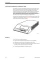
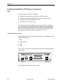
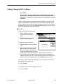
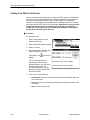
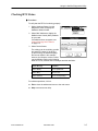
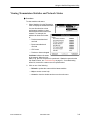
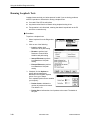
AREA CODE CHANGE
Please note that the area code for
Paradyne Corporation in Largo, Florida
has changed from 813 to 727.
For any Paradyne telephone number that
appears in this manual with an 813 area
code, dial 727 instead.
HOTWIRE 5100 DSL
ACCESS SYSTEM
CUSTOMER PREMISES
USER’S GUIDE
FOR 5170 REMOTE TERMINATION UNIT
Document No. 5100-A2-GB22-00
December 1996
Copyright 1996 Paradyne Corporation.
All rights reserved.
Printed in U.S.A.
Notice
This publication is protected by federal copyright law. No part of this publication may be copied or distributed,
transmitted, transcribed, stored in a retrieval system, or translated into any human or computer language in any form
or by any means, electronic, mechanical, magnetic, manual or otherwise, or disclosed to third parties without the
express written permission of Paradyne Corporation, 8545 126th Avenue North, P.O. Box 2826, Largo,
Florida 33779-2826.
Paradyne Corporation makes no representation or warranties with respect to the contents hereof and specifically
disclaims any implied warranties of merchantability or fitness for a particular purpose. Further, Paradyne Corporation
reserves the right to revise this publication and to make changes from time to time in the contents hereof without
obligation of Paradyne Corporation to notify any person of such revision or changes.
Changes and enhancements to the product and to the information herein will be documented and issued as a new
release to this manual.
Warranty, Sales, and Service Information
Contact your sales or service representative directly for any help needed. For additional information concerning
warranty, sales, service, repair, installation, documentation, or training, use one of the following methods:
Via the Internet: Visit the Paradyne World Wide Web site at http://www.paradyne.com
Via Telephone: Call our automated call system to receive current information via fax or to speak with a
company representative.
— Within the U.S.A., call 1-800-870-2221
— International, call 813-530-2340
Trademarks
All products and services mentioned herein are the trademarks, service marks, registered trademarks or registered
service marks of their respective owners.
Printed on recycled paper
A
December 1996
5100-A2-GB22-00
Important Regulatory Information
Important Safety Instructions
1. Read and follow all warning notices and instructions marked on the product or included in the manual.
2. When an ac power source is used, this product is intended to be used with a 3-wire grounding type plug – a plug
which has a grounding pin. This is a safety feature. Equipment grounding is vital to ensure safe operation. Do not
defeat the purpose of the grounding type plug by modifying the plug or using an adapter.
Prior to installation, use an outlet tester or a voltmeter to check the ac receptacle for the presence of earth
ground. If the receptacle is not properly grounded, the installation must not continue until a qualified electrician
has corrected the problem.
If a 3-wire grounding type power source is not available, consult a qualified electrician to determine another
method of grounding the equipment.
3. Slots and openings in the cabinet are provided for ventilation. To ensure reliable operation of the product and to
protect it from overheating, these slots and openings must not be blocked or covered.
4. Do not allow anything to rest on the power cord and do not locate the product where persons will walk on the
power cord.
5. Do not attempt to service this product yourself, as opening or removing covers may expose you to dangerous
high voltage points or other risks. Refer all servicing to qualified service personnel.
6. General purpose cables are provided with this product. Special cables, which may be required by the regulatory
inspection authority for the installation site, are the responsibility of the customer. Use a UL Listed, CSA certified,
minimum No. 26 AWG line cord for connection to the High bit-rate Digital Subscriber Line (HDSL) network.
7. When installed in the final configuration, the product must comply with the applicable Safety Standards and
regulatory requirements of the country in which it is installed. If necessary, consult with the appropriate regulatory
agencies and inspection authorities to ensure compliance.
8. A rare phenomenon can create a voltage potential between the earth grounds of two or more buildings. If
products installed in separate buildings are interconnected, the voltage potential may cause a hazardous
condition. Consult a qualified electrical consultant to determine whether or not this phenomenon exists and, if
necessary, implement corrective action prior to interconnecting the products.
9. Input power to the ac voltage configuration of this product must be provided by one of the following: (1) a UL
Listed/CSA certified power source with a Class 2 or Limited Power Source (LPS) output for use in North America,
or (2) a certified power source with a Safety Extra Low Voltage (SELV) output for use in the country of installation.
10. In addition, if the equipment is to be used with telecommunications circuits, take the following precautions:
— Never install telephone wiring during a lightning storm.
— Never install telephone jacks in wet locations unless the jack is specifically designed for wet locations.
— Never touch uninsulated telephone wires or terminals unless the telephone line has been disconnected at the
network interface.
— Use caution when installing or modifying telephone lines.
— Avoid using a telephone (other than a cordless type) during an electrical storm. There may be a remote risk of
electric shock from lightning.
— Do not use the telephone to report a gas leak in the vicinity of the leak.
5100-A2-GB22-00
December 1996
B
Important Regulatory Information
Declaration of Conformity
This Declaration of Conformity is made by Paradyne Corporation pursuant to Parts 2 and 15 of the Federal
Communications Commission’s Rules. This compliance information statement pertains to the following products:
Trade Name:
Model Number:
HOTWIRE
5170-A1-201
This device complies with Part 15 of the FCC Rules. Operation is subject to the following two conditions: (1) this
device may not cause harmful interference, and (2) this device must accept any interference received, including
interference that may cause undesired operation.
The name, address, and telephone number of the responsible party is given below:
Paradyne Corporation
8545 126th Ave. No.
Largo, Florida 33773
Phone: (813) 530-2000
C
December 1996
5100-A2-GB22-00
Contents
About This Guide
Purpose and Audience . . . . . . . . . . . . . . . . . . . . . . . . . . . . . . . . . . . . . . . . . . . iv
Guide Summary . . . . . . . . . . . . . . . . . . . . . . . . . . . . . . . . . . . . . . . . . . . . . . . . iv
Product-Related Documents . . . . . . . . . . . . . . . . . . . . . . . . . . . . . . . . . . . . . . v
1
About HotWire
What is the HotWire 5100 DSL Access System? . . . . . . . . . . . . . . . . . . . . 1-1
About the 5170 Remote Termination Unit . . . . . . . . . . . . . . . . . . . . . . . . . . . 1-2
Features . . . . . . . . . . . . . . . . . . . . . . . . . . . . . . . . . . . . . . . . . . . . . . . . . . . . . . . 1-2
Equipment and Software Requirements . . . . . . . . . . . . . . . . . . . . . . . . . . . . 1-3
HotWire 5170 RTU Diagnostics Utility . . . . . . . . . . . . . . . . . . . . . . . . . . . . . . 1-3
User Interface . . . . . . . . . . . . . . . . . . . . . . . . . . . . . . . . . . . . . . . . . . . . . . . 1-3
2
Installation
Before You Begin . . . . . . . . . . . . . . . . . . . . . . . . . . . . . . . . . . . . . . . . . . . . . . . 2-1
Package Contents . . . . . . . . . . . . . . . . . . . . . . . . . . . . . . . . . . . . . . . . . . . . . . 2-1
Installing the HotWire 5170 Remote Termination Unit . . . . . . . . . . . . . . . . 2-2
About the RTU Rear Panel . . . . . . . . . . . . . . . . . . . . . . . . . . . . . . . . . . . 2-2
Power-Up Self-Test . . . . . . . . . . . . . . . . . . . . . . . . . . . . . . . . . . . . . . . . . . . . . . 2-5
Installing the HotWire 5170 RTU Diagnostics Utility . . . . . . . . . . . . . . . . . . 2-6
5100-A2-GB22-00
December 1996
i
Contents
3
Using the HotWire Diagnostics Utility
Troubleshooting . . . . . . . . . . . . . . . . . . . . . . . . . . . . . . . . . . . . . . . . . . . . . . . . . 3-1
Accessing the Main Menu . . . . . . . . . . . . . . . . . . . . . . . . . . . . . . . . . . . . . . . . 3-3
Setting the Communication Port . . . . . . . . . . . . . . . . . . . . . . . . . . . . . . . . . . . 3-4
Setting/Changing MAC Address . . . . . . . . . . . . . . . . . . . . . . . . . . . . . . . . . . . 3-5
Setting Line Rate in Software . . . . . . . . . . . . . . . . . . . . . . . . . . . . . . . . . . . . . 3-6
Checking RTU Status . . . . . . . . . . . . . . . . . . . . . . . . . . . . . . . . . . . . . . . . . . . . 3-7
Resetting the RTU . . . . . . . . . . . . . . . . . . . . . . . . . . . . . . . . . . . . . . . . . . . . . . 3-8
Viewing Utility and Firmware Version Numbers . . . . . . . . . . . . . . . . . . . . . . 3-8
Viewing Transmission Statistics and Network Status . . . . . . . . . . . . . . . . . 3-9
Running Loopback Tests . . . . . . . . . . . . . . . . . . . . . . . . . . . . . . . . . . . . . . . . . 3-10
Loopback Test Results . . . . . . . . . . . . . . . . . . . . . . . . . . . . . . . . . . . . . . . 3-11
Downloading Firmware . . . . . . . . . . . . . . . . . . . . . . . . . . . . . . . . . . . . . . . . . . 3-12
Exiting the Utility . . . . . . . . . . . . . . . . . . . . . . . . . . . . . . . . . . . . . . . . . . . . . . . . 3-12
A
LEDs
B
Pin Assignments
DSL Interface . . . . . . . . . . . . . . . . . . . . . . . . . . . . . . . . . . . . . . . . . . . . . . . . . . . B-1
Ethernet Interface . . . . . . . . . . . . . . . . . . . . . . . . . . . . . . . . . . . . . . . . . . . . . . . B-2
Ethernet Loopback Cable . . . . . . . . . . . . . . . . . . . . . . . . . . . . . . . . . . . . . B-2
RS-232 Interface . . . . . . . . . . . . . . . . . . . . . . . . . . . . . . . . . . . . . . . . . . . . . . . . B-3
C
Technical Specifications
Glossary
Index
ii
December 1996
5100-A2-GB22-00
About This Guide
Purpose and Audience
This guide describes how to install and run diagnostics on the 5170 Remote
Termination Unit (RTU). The guide is written for users of the HotWire DSL (Digital
Subscriber Loop) access system.
Guide Summary
5100-A2-GB22-00
Section
Description
Chapter 1
About HotWire. Provides a high-level overview of the
operation of the HotWire and lists its hardware and software
requirements for installing the card in the PC.
Chapter 2
Installation. Describes how to install the RTU and Diagnostic
Utility.
Chapter 3
Using the HotWire Diagnostics Utility. Describes how to use
the HotWire Diagnostics Utility.
Appendix A
LEDs. Provides the LED descriptions.
Appendix B
Pin Assignments. Provides the pinouts for the card.
Appendix C
Technical Specifications. Provides the specifications for the
RTU.
Glossary
Defines acronyms and terms used in this document.
Index
Lists key terms, acronyms, concepts, and sections in
alphabetical order and provides page references.
December 1996
iii
About This Guide
Product-Related Documents
iv
Document Number
Document Title
5100-A2-GB20
HotWire 5100 DSL Access System Central Office
User’s Guide
December 1996
5100-A2-GB22-00
About HotWire
1
What is the HotWire 5100 DSL Access System?
Your HotWire 5170 Remote Termination Unit (RTU) is a component in the
HotWire 5100 DSL Access System. This system provides high-speed Internet or
corporate LAN access over traditional twisted-pair telephone wiring. Using your
RTU, you can connect to a Central Office (CO) to access Internet service
providers or corporate networks.
PC with
HotWire
Diagnostic
Utility
5170
Splitter*
To Internet
Service
Providers
Phone
5170
Splitter*
PC with
HotWire
Diagnostic
Utility
Central
Office
Phone
Brouter
Domain
Name Server
*A splitter is an interface device installed by a CO technician
outside your premises.
5100-A2-GB22-00
December 1996
496-15203
1-1
About HotWire
About the 5170 Remote Termination Unit
The HotWire 5170 RTU is a standalone unit designed for the home office users
with a local area network (LAN). It provides high-speed internet access via the
DSL interface to a central office. The built-in Rate Adaptive DSL (RADSL)
technology enables the unit to automatically communicate with the central office
at the maximum possible operating rate. The RTU communicates with your
IBM-compatible 80486 (or higher) PC using your Ethernet network interface card
(NIC). The supplied windows-based diagnostics utility enables users to check
RTU status, network transmission status, and run diagnostic tests.
As shown in the following illustration, the RTU front panel provides several LEDs
to indicate RTU operating status. Refer to Appendix A for the descriptions of the
LEDs and their operational status indications.
5170
PWR
SYS TE
ST
TX
RX
DSL LINK
CD LN
K TX
RX
COL JA
B
LAN
496-15216
Features
Your 5170 RTU has the following features:
1-2
Supports CAP Rate Adaptive Digital Subscriber Loop (CAP RADSL)
High-speed access rates which vary depending on the RADSL
Security features in the HotWire CO hardware that prevent remote users from
accessing another remote user’s PC files or LAN traffic
Prevention against degradation of telephone service
December 1996
5100-A2-GB22-00
About HotWire
Equipment and Software Requirements
Verify that you have the following hardware and software before installing the
RTU.
Hardware Requirements
80486 (or higher) IBM PC or compatible
8 MB RAM minimum (16 MB RAM recommended)
One 1.44 MB, 3 1/2″ diskette drive (for installation)
2 MB free disk storage (for program files)
Software Requirements
DOS 5.0 or later
Windows 3.1 (or later) and TCP/IP application with IP stack NDIS 2.01
compliant or Windows For Workgroups 3.11 (or later) or Windows 95
HotWire 5170 RTU Diagnostics Utility
Use the HotWire Diagnostics Utility supplied with the RTU for running diagnostics
and tests for troubleshooting the unit or downloading firmware. The Diagnostics
Utility provides screen help in standard windows format. Refer to Chapter 3,
Using the HotWire Diagnostics Utility, for more information on this utility.
User Interface
The Diagnostics Utility uses standard Windows user interface conventions for all
windows including Help screens.
5100-A2-GB22-00
December 1996
1-3
Installation
2
Before You Begin
1. Check your package contents.
2. Review software and hardware requirements in Chapter 1.
3. Begin installation.
Package Contents
Your HotWire 5100 RTU package should contain the following:
5100-A2-GB22-00
HotWire 5170 Remote Termination Unit
HotWire 5170 Diagnostics Utility disk
RS-232 Cable (serial port connection)
6-pin modular cable (DSL connection)
8-pin Ethernet Cable (Ethernet connection)
HotWire 5100 DSL Access System Customer Premises User’s Guide for
5170 Remote Termination Unit
December 1996
2-1
Installation
Installing the HotWire 5170 Remote Termination
Unit
For RTU installation, you need the following:
Cables and cord supplied in your HotWire 5170 RTU package.
A DSL access point already installed and near the location of the RTU.
An Ethernet card already installed in your PC.
An available 110V ac power source.
You may also want a small screwdriver to secure your serial port connectors. If
you ever need to perform the External Ethernet loopback test on your Ethernet
card, you will also need an Ethernet Loop cable. This is not supplied with your
RTU but the pin assignments and wiring to make this cable, along with the pin
assignments for all the other cables, are provided in Appendix B.
About the RTU Rear Panel
The following figure shows the rear panel for your RTU. The installation uses the
following jacks and port:
DSL
Serial (optional)
LAN
PWR
The V.35 port is not used but is included to accommodate future enhancements
to this product.
PWR
LAN
DSL
SERIAL PORT/V.35
0
1
496-15215
Use the following procedure to install your RTU.
2-2
December 1996
5100-A2-GB22-00
Installation
Procedure
1. Turn Off your PC. Place your RTU on a flat surface near the PC.
2. Insert the DSL cable 6-pin plug into the jack marked DSL on your RTU. Insert
the other end of the cable into the DSL network access point.
DSL
PWR
0
LAN
SERIAL PORT/V.35
1
DSL
Cable
496-15207
.
3. This step is optional. Make this RS-232 connection only to accommodate
running the 5170 Diagnostic Utility. See Chapter 3, Using the HotWire
Diagnostics Utility, for a description of this utility.
Insert the 25-pin connector on the RS-232 cable into the connector marked
SERIAL PORT on your RTU. Insert the other end of the cable into the serial
port on your PC.
DSL
PWR
0
LAN
SERIAL PORT/V.35
1
RS-232
Cable
496-15208
.
5100-A2-GB22-00
December 1996
2-3
Installation
4. Insert the Ethernet cable 8-pin plug into the jack marked LAN on your RTU.
Insert the other end of the cable into the Ethernet jack on the Ethernet card in
your PC.
DSL
PWR
LAN
SERIAL PORT/V.35
1
0
Ethernet
Cable
496-15209
5. Connect the small power connector into the jack marked PWR on your RTU.
Plug the transformer end of the power cord into a 110V ac power outlet.
Power
On/Off
DSL
PWR
0
LAN
SERIAL PORT/V.35
1
Power
Cable
496-15210
2-4
December 1996
5100-A2-GB22-00
Installation
6. Turn on your PC.
7. Turn on the power switch on your RTU (see rear panel illustration). Verify that
the LEDs function as indicated in the following illustration:
5170
PWR
SYS TE
ST
TX
RX
CD LN
K TX
DSL LINK
RX
COL JA
B
LAN
The SYS LED turns
solid green. Refer to
the Power-Up Self-Test
section following this
procedure if the
SYS LED does not
turn green.
496-15217
The CD LED blinks and then both
the CD and LNK LEDs turn solid
green. This indicates that the card
is communicating with the central
office unit, meaning your DSL link
is operational. If the CD and LNK
LEDs do not function as stated,
contact your customer service
representative for assistance.
Installation is completed. You can begin using your DSL connection. Refer to
Troubleshooting in Chapter 3 if you encounter problems during normal RTU
operation.
Power-Up Self-Test
Whenever you turn on your RTU or after the reset operation is selected in the
Diagnostics Utility, a power-up self-test is automatically performed on the RTU to
ensure that the unit is installed and functioning properly. The self-test includes a
basic hardware test and verification of internal components. The SYS (system)
LED state identifies the following conditions by:
Turning solid green if the test is successful.
Turning Off if the test fails.
If the test fails, turn power Off and On. You may also use the diagnostics utility to
reset the device; see Resetting the RTU in Chapter 3. If the test continues to fail,
contact your customer service representative for assistance.
5100-A2-GB22-00
December 1996
2-5
Installation
Installing the HotWire 5170 RTU Diagnostics Utility
The RS232 cable must be connected between the RTU and your PC before you
can run the Diagnostic Utility.
Procedure
To install the Diagnostics Utility:
1. Insert the HotWire 5170 RTU Diagnostics Utility disk into drive a:.
2. Enter Windows and:
If you are . . .
Select . . .
On the Program Manager window
File, then Run.
Using Windows 95
Start, then Run.
3. Type A:\SETUP.EXE and click on OK.
4. Follow the screen instructions for installing the software. When the install
program prompts for a destination directory for the Diagnostics Utility, you
can specify a directory or click on Next to accept the default directory.
5. Click on OK when installation completes.
An icon is created for the utility. You can double-click on the icon to start the utility
when needed.
NOTE:
The Diagnostics Utilities interferes with network data and operation of the
RTU so the Diagnostics Utility should not be running, either in the open state
or iconified, during normal RTU operation.
When you first access the utility, you must configure the COM port used for the
RS-232 connection. The following window prompts you to do this. Refer to
Setting the Communication Port in Chapter 3 for more information.
2-6
December 1996
5100-A2-GB22-00
Using the HotWire Diagnostics
Utility
3
Troubleshooting
Typically, you run your Diagnostics Utility to help troubleshoot your RTU. Review
the following symptoms and possible solutions to help in solving any problems
you may encounter during RTU operation. To use the utility, refer to Accessing
the Main Menu.
Symptom
Possible Cause
Possible Solution
RTU does not
power On.
Power cord is
loose.
1. Check power cord.
Front panel LNK
Bad DSL
and/or CD LEDs are connection.
off.
2. Try a different AC outlet.
1. Attempt to reset the RTU; see Resetting
the RTU.
2. Check the DSL connection.
3. Contact customer service
representative.
Not receiving data.
Network Link is
down.
MAC address not
acquired or set.
Ethernet Port not
functioning
properly.
1. Check if link is up, see Viewing
Transmission Statistics and Network
Status. Run Remote Loopback test; see
Running Loopback Tests.
2. Display MAC Address; see Checking
RTU Status. If the MAC address was
not acquired or set, try to issue a
request on the TCP/IP stack. Wait for 1
minute and try to display the MAC
address again. If the MAC address is
not set, see Setting/Changing MAC
Address.
3. Perform External Ethernet Loopback to
determine if the port is working; see
Running Loopback Tests.
5100-A2-GB22-00
December 1996
3-1
Using the HotWire Diagnostics Utility
Symptom
Possible Cause
Possible Solution
Experiencing
several errors while
transferring files.
Bad connection to
the CO.
1. Run local Loopback test; see Running
Loopback Tests.
Bad Ethernet card.
2. Run Remote Loopback test.
Bad Ethernet
cable.
3. Run Ethernet Loopback test.
4. Attempt to reset the 5170 unit; see
Resetting the RTU.
5. Contact your customer service
representative.
Cannot connect to
Central Office.
Network Link is
down.
1. Run a Remote Loopback test; see
Running Loopback Tests.
Network cable not
connected.
2. If Remote Loopback test is successful,
check Link State; see Viewing
Transmission Statistics and Network
Status.
3. If link is up, check network cable
connection.
Cannot run
diagnostics. System
hangs.
3-2
1. Restart Diagnostic utility.
2. Contact your customer service
representative.
December 1996
5100-A2-GB22-00
Using the HotWire Diagnostics Utility
Accessing the Main Menu
You can use the Diagnostics Utility to check the health and status of the RTU.
This utility also provides the capability to download firmware and run diagnostic
tests on the unit when instructed by a central office technician. You must have
installed the RS-232 connection to use this utility (see Chapter 2, Installation).
To access the utility, double-click on the HotWire icon while in Windows. The
following window appears.
NOTE:
The Diagnostics Utility interferes with network data and operation of the RTU
so the Utility should not be running, in either the open or iconified state,
during normal RTU operation.
From the main menu, click on:
5100-A2-GB22-00
File to exit the utility.
Configuration to access selections for changing the MAC Address or Line
Speed, setting the COM port for the RS-232 connection, and downloading
firmware updates.
Diagnostics to access selections for checking RTU status, viewing
performance statistics, and running loopback tests.
Help to access screen help.
December 1996
3-3
Using the HotWire Diagnostics Utility
Setting the Communication Port
Use the following procedure to specify the COM port on your PC used for the
RS-232 connection to the RTU.
NOTE:
You must have installed the RS-232 connection between the PC and the RTU
for this COM port setting to take effect and to use this utility appropriately.
Refer to Installing the HotWire 5170 Remote Termination Unit in Chapter 2.
" Procedure
To set the COM port:
1. Select COM Port Configuration from
the Configuration menu.
2. Click on the COM port used as the
connection between your PC and the
RTU.
3. Click on OK to accept the entry and
close the window.
To close the window without setting the
COM port:
H
3-4
Click on Cancel.
December 1996
5100-A2-GB22-00
Using the HotWire Diagnostics Utility
Setting/Changing MAC Address
CAUTION:
Be sure you understand the purpose of the MAC Address before using
this procedure. Setting the MAC Address incorrectly will affect data
transmission. Contact your customer service representative if you have
questions.
Usually, the MAC address automatically acquires the MAC level address of the
host PC. This address is required by the RTU to communicate with the central
office. Generally, users should not change this address. However, if the address
acquired is not correct or if you are changing Ethernet cards on your PC, you will
need to change the MAC address accordingly.
" Procedure
To access the MAC Address window:
1. Select Advanced Hardware
Setup from the Configuration
menu.
2. Select MAC Address to display
the MAC Address window.
To change an incorrect address:
1. Get MAC address from the Ethernet
card.
2. Use your keyboard to enter the new
MAC address in the field provided.
Be sure to use the correct address
format. (The address must be entered
in hexadecimal format with no spaces or dashes between the values.)
3. Click on OK to accept the MAC address change. Using the OK operation
disables automatic mode. This means that the system will not acquire or set
the MAC address automatically again until the Reset operation is used.
To acquire the MAC address automatically (return to automatic mode after the
MAC address was manually set):
H
Click on Reset.
To close the window without changing the address:
H
5100-A2-GB22-00
Click on Cancel.
December 1996
3-5
Using the HotWire Diagnostics Utility
Setting Line Rate in Software
You can view and/or set the line rate to match your RTU using the Configuration
option. It is highly recommended that the Transmit and Receive rates remain at
the maximum rate possible which is set to be the default. This enables the
software to use the highest rate available as the operating rate when the central
office card and your RTU link up to communicate. Otherwise, be sure you know
the appropriate line rate for your RTU before changing this selection or
contact your customer service representative for assistance. Selecting the
wrong rate can terminate your DSL link.
Procedure
To change line rate:
1. Select Configuration from the
HotWire main menu.
2. Select Advanced Hardware Setup.
3. Select Line Rate.
4. Set the appropriate Transmit and
Receive rates for your RTU.
If necessary, use
display.
to scroll the
The Current operating rate
indicates the maximum rate
possible between your RTU and
the central office card. The
Current operating rate may be
different from the Transmit Rate
and Receive Rate.
5. Click on one of the following:
— Save Speed to save the selected transmit and receive speeds and return
to the main menu.
— Cancel to close the Link Rates window without changes and return to the
main menu.
— Help to access screen help.
3-6
December 1996
5100-A2-GB22-00
Using the HotWire Diagnostics Utility
Checking RTU Status
" Procedure
To verify that the RTU is functioning properly:
1. Select Hardware Status from the
Diagnostics menu to display the
Hardware Status window.
2. Select MAC Address to display the
Media Access Control (MAC) address
for your card.
If an address does not appear, see
Setting/Changing MAC Address
on page 3-5.
3. Select Device Status.
The window can be scrolled to provide
the latest RTU status. If the RTU is
up and running, the window displays
the lines as shown in the example;
however, the firmware version number
may be different. Refer to the following
table for a list of possible status messages and their definition.
Status Message
Definition
Device Ready
RTU is operational.
Device Busy
RTU is in use.
Device Timeout
RTU is not responding.
For window operations, click on:
5100-A2-GB22-00
H
Exit to close the window and return to the main menu.
H
Help to access screen help.
December 1996
3-7
Using the HotWire Diagnostics Utility
Resetting the RTU
Use the Reset operation to reinitialize the RTU. You may want to check Device
Status. See Checking RTU Status before using the reset operation to correct
inconsistent or incorrect status. The reset operation performs a power-up self-test
on the card as described in Chapter 2, Installation.
Procedure
1. Select Hardware Status from the
Diagnostics menu to display the
Hardware Status window.
2. Select Reset Device.
After using reset, check the Device
Status again to determine the
RTU’s operational status.
Viewing Utility and Firmware Version Numbers
Procedure
To view the version number of the Diagnostic Utility and the firmware currently
used in the RTU:
1. Select Help from the Main menu.
2. Select About.
The About HotWire Diagnostics window displays the version numbers. To
update your firmware, refer to the procedure in Downloading Firmware on
page 3-12.
3-8
December 1996
5100-A2-GB22-00
Using the HotWire Diagnostics Utility
Viewing Transmission Statistics and Network Status
Procedure
To view statistics and status:
1. Select Statistics from the Diagnostics
menu to display the Statistics window.
You use this selection to view
performance statistics on data
transmissions and the state of the
network. For example, the
window can show the number
of:
— Packets transmitted and
received
— Bytes transmitted and
received
— CRC errors
— Packets or frames dropped
Link State indicates the status
of the network. When the Link
State is Up, the DSL connection is operational. If Statistics reports that the
Link State is Down, see Troubleshooting on page 3-1. If troubleshooting
efforts fail, contact the customer service representative.
2. Click on one of the following:
— Refresh to update the screen with the latest statistics.
— Help to access screen help.
— Cancel to close the window and return to the main menu.
5100-A2-GB22-00
December 1996
3-9
Using the HotWire Diagnostics Utility
Running Loopback Tests
Loopback tests can help you isolate areas of trouble if you are having problems
with RTU operation or transmission. During a loopback test:
H
Your card’s Test LED is solid yellow.
H
Any data received from the network during loopback testing is lost.
H
Test operation is uni-directional, meaning that data is looped back to the PC
end of the connection only.
" Procedure
To perform a loopback test:
1. Select Loopback from the Diagnostics
menu.
2. Click on one of the following:
— Local to perform local
Databus to RTU path testing
— Remote to perform local
Databus to Central Office
HotWire card path testing
— Internal Ethernet to perform
local Databus to LAN path
testing
— External Ethernet to perform
local Databus to LAN path
testing
3. If desired, click on Options to
specify the test parameters
identified in the Loopback Options
screen. If not, go to Step 4.
The Loopback Options screen enables
you to specify:
— Packet Count to indicate the
number of packets to be tested.
The default is 10.
— Packet Size to indicate the size of packets to be tested. The default is
64 bytes.
3-10
December 1996
5100-A2-GB22-00
Using the HotWire Diagnostics Utility
For the options window operation, select the values to be used during the test
and/or click on:
— OK to accept the parameters and return to the Loopback window.
— Cancel to close the window without accepting any values and return to
the Loopback Test Options screen.
— Help to access screen help.
4. Click on one of the following:
— Start to start a test.
— Exit to close the window and return to the main menu without running a
test or after running a test and viewing results.
— Help to access screen help.
Loopback Test Results
When the test completes, the Loopback window displays the summary of the
Loopback results, including the:
Values of the relevant counters for the number of requests (packets) sent.
Replies received and the success rate.
Average Round Trip (RT) delay distribution.
Reports on any errors found or packets dropped.
NOTE:
If you cannot run a successful local loopback test, retry the test one or two
times before contacting your customer service representative. However,
before running a remote loopback test, you should always contact your
customer service representative. Also, report a failed remote loopback test to
your customer service representative.
5100-A2-GB22-00
December 1996
3-11
Using the HotWire Diagnostics Utility
Downloading Firmware
Use the following procedure to download firmware updates from a disk or virtual
hard drive.
Procedure
To download firmware:
1. Select Download Firmware from the
Configuration menu on the Diagnostics
Utility main menu.
The Open window appears. This
window uses standard Windows user
interface conventions.
Notice that the Open
window may look
slightly different on a
Windows 95 system.
2. Select the appropriate
drive (for example,
drive a:) as shown on
the sample Open
window. (It is
recommended that
you copy the update
file to your hard drive and then download. Downloading from the a: drive is
significantly slower than downloading from the hard drive.)
3. Select the file.
4. Click on one of the following:
— OK to accept the parameters and return to the main menu.
— Cancel to close the window without downloading firmware and return to
the main menu.
Exiting the Utility
To quit the Diagnostics Utility, select Exit from the File menu.
3-12
December 1996
5100-A2-GB22-00
LEDs
A
The HotWire RTU has eleven functional LEDs. The following illustration shows
the location of the LEDs on the faceplate. Table A-1 interprets the status of the
card when the LEDs are on, off, or blinking.
RSU
Status
PWR
SYS
TEST
DSL
Connector
TX
RX
CD
Ethernet
Connector
LNK
TX
RX
COL
JAB
5170
DSL LINK
LAN
496-15214
Table A-1. Front Panel LED Descriptions and Status (1 of 2)
Type
LED
LED is . . .
Indicating . . .
System
SYS
Blinking
Self-test in progress. Occurs at power-up.
Off
Error condition. Self-test failed.
On
Normal operation. Self-test successful.
Blinking
Normal operation.
TEST
5100-A2-GB22-00
December 1996
A-1
LEDs
Table A-1. Front Panel LED Descriptions and Status (2 of 2)
Type
LED
LED is . . .
Indicating . . .
DSL
TX
Blinking, On
Normal operation. Indicates presence of DSL
traffic.
Off
No data being sent.
Blinking, On
Normal operation. Indicates presence of DSL
traffic.
Off
No data being received.
Blinking
Normal operation. Carrier detect training mode.
On
Normal operation. Data Mode.
Off
No carrier.
On
Normal operation.
Off
Link down.
Blinking, On
Normal operation. Indicates presence of LAN
traffic.
Off
No data being sent.
Blinking, On
Normal operation. Indicates presence of LAN
traffic.
Off
No data being received.
Blinking
Presence of a collision.
Off
Normal operation. No collisions.
Blinking
Presence of a jabber condition.
Off
Normal operation.
RX
CD
LNK
LAN
TX
RX
COL
JAB
If any of the states defined in the table as “Error Conditions” occurs, reset the
RTU using the Diagnostics Utility. If the error condition persists, attempt to run the
loopback tests as described in Chapter 3, Using the HotWire Diagnostics Utility.
A-2
December 1996
5100-A2-GB22-00
Pin Assignments
B
DSL Interface
Table B-1 defines the pinouts for the DSL connector. It is a 6-pin, non-keyed,
modular-jack female connector.
Table B-1. DSL Connector Pin Assignments
Pin#
Use
1
NC
2
NC
3
RING
4
TIP
5
NC
6
NC
NC = Not connected (unused).
5100-A2-GB22-00
December 1996
B-1
Pin Assignments
Ethernet Interface
Table B-2 defines the pinouts for the Ethernet connector. It is an 8-pin,
non-keyed, modular-jack female connector.
Table B-2. Ethernet Pin Assignments
Pin#
Use
1
TX Data +
2
TX Data –
3
RX Data +
4
NC
5
NC
6
RX Data –
7
NC
8
NC
NC = Not connected (unused).
Ethernet Loopback Cable
To make an Ethernet Loopback cable, refer to Ethernet Pin Assignments,
Table B-2, and do the following at the opposite end of the 8-pin connector:
1. Connect Pin 1 (TX Data +) to Pin 3 (RX Data +)
2. Connect Pin 2 (TX Data –) to Pin 6 (RX Data –)
B-2
December 1996
5100-A2-GB22-00
Pin Assignments
RS-232 Interface
Table B-3 defines the pinouts for the RS-232 connector. This serial connector is a
Dual DB 25-pin.
Table B-3. RS-232 Interface Cable Pin Assignment
5100-A2-GB22-00
Pin Number
RS-232
Description
1
Ground
Protective Ground
2
232-TD
Transmit Data
3
232_RD
Receive Data
4
232_RTS
Request To Send
5
232_CTS
Clear To Send
6
232_DSR
Data Set Ready
7
Ground
Signal Ground/Common Return
8
232_CD
Received Line Signal Detect/Carrier Detect
9
NC
Receive Data Clock B
10
NC
11
NC
External Clock B
12
NC
Transmit Data Clock B
13
NC
14
NC
Transmit Data B
15
NC
Transmit Data Clock A
16
NC
Receive Data B
17
NC
Receive Data Clock A
18
NC
19
NC
20
232_DTR
21
NC
22
NC
23
NC
24
NC
25
NC
Data Terminal Ready
External Clock A
December 1996
B-3
Technical Specifications
C
Table C-1 lists the technical specifications for the Customer Premises Remote
Termination Unit (RTU).
Table C-1. Technical Specifications
Specifications
Criteria
Analog Interface
RTU includes an RJ11 connector for use with a CAP
(Carrierless Amplitude and Phase) Modulation RADSL
multi-speed. RJ45 connector for Ethernet LAN
connection.
Management
RSU supports local diagnostic and test support via
Diagnostics Utility.
Power Consumption
Less than 8 watts.
Operating Environment
Ambient Temperature: 50° to 120° F (10° to 50° C)
Relative Humidity: 5% to 90% non-condensing
Shock and vibration sufficient to withstand normal
shipping
5100-A2-GB22-00
December 1996
C-1
Glossary
CO
Central Office.
CP
Customer Premises.
CPE
Customer Premises Equipment. Terminal equipment supplied by either the customer or
some other supplier, which is connected to the telecommunications network.
CPU
Central Processing Unit.
CRC
Cyclic Redundancy Check. A commonly used method of error detection.
DSL
Digital Subscriber Loop. The non-loaded, local-loop copper connection between the
customer and the first node within the network.
E1
A data signaling rate common outside the United States. A wideband interface operating at
2.048 Mbps defined by CCITT standards G.703 and G.704.
HDSL
High-bit-rate Digital Subscriber Loop. Provides high bandwidth, bi-directional transmission
over copper wire for both T1 and E1 services.
Internet
Worldwide interconnected networks that predominantly use the TCP/IP protocol.
LAN
Local Area Network. A network that spans a small geographic area (e.g., a building).
LEDs
Light Emitting Diodes. Indicators on a device that usually show the status of a component.
LEDs may have three states: blinking, on or off.
MAC Address
Media Access Control address. Virtual address that identifies a CP card for the central
office system.
POTS
Plain Old Telephone Service.
RADSL
Rate Adaptive Digital Subscriber Loop.
TCP/IP
Transmission Control Protocol/Internet Protocol. The predominant protocol in the
worldwide Internet.
T1
A data signaling rate common in the United States. A term for a digital carrier facility used
to transmit a DS1 formatted signal of 1.544 Mbps.
5100-A2-GB22-00
December 1996
GL-1
Index
A
H
Analog Interface, C-1
Hardware Setup, window, 3-6
Hardware Status, window, 3-7, 3-8
C
Central Office, 1-1
Configuration Menu, 3-3
Download Firmware, 3-12
Hardware Setup, 3-6
CRC Errors, 3-9
D
Device Messages, Device Ready, 3-7
Diagnostics Menu, 3-3
Hardware Status, 3-5, 3-7, 3-8
Loopback Tests, 3-10
Statistics, 3-9
Diagnostics Utility, 1-3
exiting, 3-12
icon, 3-3
installing, 2-6
main menu, 3-3
Digital Subscriber Loop, iii
Disk
requirements, 1-3
storage, 1-3
F
File Menu, 3-3
Exit, 3-12
Firmware, downloading, 3-12
I
Installation, diagnostics utility, 2-6
L
LEDs, 1-2, A-1
during loopbacks, 3-10
SYS, 2-5
Line Rate, setting, 3-6
Link Status, 3-9
Local Loopback Test
failed, 3-11
setting options, 3-10
M
MAC Address, changing, 3-5
N
NAS Card
operating environment, C-1
power consumption, C-1
Network
interference, 2-6, 3-3
status, 3-9
P
Packet
count, 3-10
size, 3-10
transmissions, 3-9
Pin Assignments, B-1, B-2
5100-A2-GB22-00
December 1996
IN-1
Index
R
T
RADSL (Rate Adaptive Digital Subscriber Loop), 1-2
RAM Requirements, 1-3
Remote Loopback Test
failed, 3-11
setting options, 3-10
Reset RSU, 3-8
TCP/IP, version, 1-3
W
Windows 3.1, version, 1-3
Windows 95, version, 1-3
Windows for Workgroups, version, 1-3
S
Self-Test, 2-5
SETUP.EXE, 2-6
Statistics
byte transmissions, 3-9
CRC errors, 3-9
packet transmissions, 3-9
viewing, 3-9
window, 3-9
System Messages
Device Busy, 3-7
Device Timeout, 3-7
System Requirements
hardware, 1-3
software, 1-3
IN-2
December 1996
5100-A2-GB22-00