1
MODELS DESCRIBED IN THIS MANUAL
AT650, GS650 (650VA)
AT800, GS800 (800VA)
AT1200, GS1200 (1200VA)
AT1600, GS1600 (1600VA)
AT2300, GS2300 (2300VA)
OWNER'S MANUAL
TABLE OF CONTENTS
PAGE
Introduction ………………………………………………………………. 1
Receiving Inspection …………………………………………………… 1
Warranty Registration ………………………………………………….. 1
Important Safety Instructions ………………………………………….. 1
Selection of UPS Location ……………………………………………… 2
Electrical Specifications ………………………………………………… 3
Other Electrical Specifications ………………………………….4
Physical Specifications ………………………………………………….. 4
Unit Description ………………………………………………………….. 5
GS Models ……………………………………………………….. 6
Installation and Preliminary Testing …………………………………….6
Load Testing ……………………………………………………………....7
Operation …………………………………………………………………..7
System Batteries …………………………………………………………. 8
Battery/System Checkout ……………………………………………….. 9
UPS Monitoring Configurations ………………………………………… 9
UPS Direct Interface Configurations …………………………... 9
UPS DB9 PIN Out ……………………………………………….. 10
Service …………………………………………………………………….. 10
Common UPS Problems ………………………………………... 10
Policy and Instructions for Return of
Product to Para Systems, Inc ………………………………….11
Warranty Statement ………………………………………………………. 12
Warranty Registration …………………………………………………….. 12
INTRODUCTION
Congratulations on your purchase of a MINUTEMAN "AT" Series Synchronized Sinewave
Uninterruptible Power Supply (UPS). Each unit is designed to provide superior, total power
protection for personal computers, telephone systems and any other sensitive or critical electronic
equipment against all commercial power anomalies. These models provide light and audible
alarm indications, so the user will know the status of both commercial power and the
MINUTEMAN "AT" Power Supply at all times. Each unit is designed to be maintenance free and
to provide years of excellent service. Other features of the "AT" Series include:
Light weight and small footprint
Quiet operation
High non-linear current capability
(Crest Ratio = 3:1)
Computer grade sinewave output
LAN Communications Port
RECEIVING INSPECTION
Remove and inspect the unit for shipping damage. If damage is found, immediately notify the
carrier and your dealer. If no damage is found save both the shipping container and the packing
foam in case the unit may later need to be returned to the factory or shipped to another location.
WARRANTY REGISTRATION
Locate your warranty registration card in the back of this manual and complete and return within
10 days of receipt of the unit(s) to register your warranty. Failure to register your warranty
renders it non-valid.
IMPORTANT SAFETY INSTRUCTIONS
(Save these instructions)
Units in this manual are intended for installation in a temperature-controlled, indoor area
free of conductive contaminants.
Read all instructions carefully before operating the UPS. All operating instructions should
be followed and all cautions must be adhered to.
CAUTION -- UPS units use batteries for generation of AC voltages, so output receptacles
may be electrically hot even when the unit is not connected to commercial power.
Trained service personnel should perform all repairs, since an electrical shock hazard
exists.
CAUTION -- Do not remove the cover, there are no user serviceable parts inside.
CAUTION -- The 3-wire plug supplied with the unit provides earth ground for the UPS
unit chassis to prevent electrical shock. Plug the UPS unit into a 3-wire grounding type,
commercial receptacle with grounding conductor connected to earth ground at the
service equipment. Removal of the ground pin from the plug or use of a 3-wire-to-2-wire
adapter will defeat this safety feature and may result in a shock hazard. Additionally, if
1
the plug is removed to simulate a power failure (not recommended), do not touch the plug
conductors or the chassis while the lug is removed.
CAUTION -- Do not allow water or any foreign object to enter the UPS. In case this
occurs, immediately turn the unit power switch off and unplug the MINUTEMAN from the
commercial receptacle.
Servicing of batteries should be performed or supervised by personnel knowledgeable of
batteries and the required precautions. Keep unauthorized personnel away from the
batteries.
When replacing UPS batteries, use sealed lead-calcium rechargeable batteries with the
same voltage and ampere-hour rating as those contained in the units. These batteries
have pressure operated safety vents.
CAUTION
1. Do not dispose of batteries in a fire. They may explode.
2. Do not open or mutilate batteries. Released electrolyte is harmful to the skin and
eyes, and may be toxic.
3. Battery systems can present a risk of electrical shock and high short circuit current.
The current capability of each battery system is sufficient to burn large wire or tools
very rapidly, producing molten metal. The following precautions should be observed
when working on batteries:
a. Disconnect charging source prior to connecting or disconnecting battery
terminals.
b. Remove watches, rings or other metal objects.
c.
Use tools with insulated handles.
d. Do not lay tools or any metal parts on top of batteries.
e. Wear protective gloves, eyewear, and boots.
f.
Determine if the battery is inadvertently grounded. If inadvertently grounded,
remove source of ground. Contact with any part of a grounded battery can
result in an electrical shock. The likelihood of such shock will be reduced if
such grounds are removed during installation and maintenance.
SELECTION OF UPS LOCATION
Select a location that will provide good air circulation for the UPS. Do not cover the unit air vent
holes or restrict airflow in any way. The unit must have good air circulation at all times.
Avoid locations near heating devices.
Avoid locations near water or excessive humidity.
Avoid locations where the unit is exposed to direct sunlight.
2
Route unit power-cords so it cannot be walked on or damage.
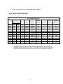
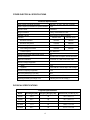
ELECTRICAL SPECIFICATIONS
Electrical Specifications
Battery
Rated Output
Time
Max Heat
Freq.
Input
Output
System
Back Up
(Min)
Dissipation
Half Load
BTU/HR
VA
Watts
HZ
VAC/A
VAC/A
VDC
Full Load
AT650
650
455
60
120/6.0
120/5.4
24
6
15
311
GS650
650
455
50
220/3.3
220/3.0
24
6
15
311
AT800
800
560
60
120/7.4
120/6.7
48
8
20
382
GS800
800
560
50
220/4.0
220/3.6
48
8
20
382
AT1200
1200
840
60
120/11.1
120/10.0
48
7
18
573
GS1200
1200
840
50
220/6.1
220/5.5
48
7
18
573
AT1600
1600
1120
60
120/14.8*
120/13.3*
72
8
20
765
GS1600
1600
1120
50
220/8.1
220/7.3
72
8
20
765
AT2300
2300
1610
60
120/21.3
120/19.2
72
4
10
1099
GS2300
2300
1610
50
220/11.6
220/10.5
72
4
10
1099
Model
* Input/Output specifications above for model AT1600 are applicable when a 20-ampere power
plug (NEMA 5-20P) is utilized (non-standard). For a NEMA 5-15P plug (standard), derate input to
120VAC/12 Amperes and derate output in "AC Normal" mode only to 120VAC/10.8 Amperes.
3
OTHER ELECTRICAL SPECIFICATIONS
Electrical Specifications
Input Voltage (AC Mode Function)
120VAC ± 15 VAC; 225 VAC ± 35VAC
Input Frequency Deviation for Synchronization
± 5%
Inrush Current
1.5xRated
Surge Protection
3 way, meets IEEE STD 587
RFI/EMI Filtering
Both Common & Normal Modes
Transfer
120VAC Units
220VAC Units
Brownout Transfer
105VAC
190VAC
Brownout AC Return
110VAC
200VAC
Over-voltage Transfer
135VAC
260VAC
Over-voltage AC Return
130VAC
250VAC
Transfer Speed
2ms Maximum
Inverter Crest Factor (Non-Linear Load)
3:1
Inverter Waveform
Synchronized Computer Grade Sinewave
Harmonic Distortion
Less than 3% THD at full linear load
Inverter Voltage Regulation
Static
± 3%
Dynamic
± 5% with 50% Linear Step Load Change
Inverter Frequency Regulation
0.5%
DC-to-AC Efficiency (Full Load)
80%
Overload/Short Circuit Protection
Yes, Electronic and Fuse
Discharged Battery Recharge Time
8 Hours (95% of Full Charge )
PHYSICAL SPECIFICATIONS
Physical Specifications
Model
Net Weight (LBS)
Shipping Weight (LBS)
Dimensions (L x W x H) (In.)
AT650
36.0
39
16.5 x 6.5 x 9.7
AT800
42.7
46
18.1 x 6.5 x 9.7
AT1200
62.4
67
19.0 x 7.9 x 13.3
AT1600
77.3
82
19.0 x 7.9 x 13.3
AT2300
92.1
96
21.7 x 7.9 x 13.9
4
All Models:
Operating Temperature
0ºC to 40ºC (32ºF to 104ºF)
Storage Temperature
-15ºC to 40ºC (5ºF to 104ºF)
Relative Humidity
95% maximum at 25ºC Non-Condensing
Audible Noise
40 dB ANSI Scale A, at 3'
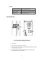
UNIT DESCRIPTION
AT SYCHRONIZED SINEWAVE MODELS
1. Power Switch.
2. Alarm Silencer/Test momentary rocker switch.
3. AC Normal LED (Green): On when commercial voltage is present and in range
(AC Normal Mode), off otherwise.
4. AC Fail LED (Red): On when commercial power is lost and stays on until
commercial power returns, off otherwise.
5
5. AC Fault LED (Yellow/Red): Yellow when commercial input voltage is lost or too
low or input frequency shifts drastically and unit switches to inverter mode. Red
when commercial input voltage is too high and unit switches to inverter mode.
Both stay on until fault is cleared. Off as long as commercial voltage is present
and in range, and frequency is stable.
6. Battery Status LED (Yellow/Red): Yellow at low battery warning. Red at low
battery cutoff for one (1) second. Off otherwise.
7. Overload LED (Red): On when inverter shuts down because of unit overload or
because input frequency is far out of range, off otherwise. Overload LED stays
on until unit power switch is turned off and back on with conditions corrected.
8. Fuse/Breaker Fault LED (Red): On when AC fuse (AT650, AT800 or AT2300) is
blown or AC Breaker (AT1200 or AT1600) is tripped, off otherwise.
9. Output Receptacles, 120VAC units: 4 NEMA 5-15R receptacles on all units
except AT2300. AT2300 has 6.
10. Power Cord, 120VAC units: AWG 18/3 (AT650 and AT800) or AWG 14/3
(AT1200 and AT1600) SJT with NEMA 5-15P Plug (standard) or AWG 12/3 SJT
(AT2300) with NEMA L5-30P Plug.
11. Input Fuse Holder/Breaker: At650, AT800 and AT2300 units use fuse and fuse
holder at input. AT1200 and AT1600 units use AC circuit breaker at input.
12. LAN Communications Port (DB9 Female): Standard on all units.
13. Cooling Fan: Models AT1200, AT1600 an AT2300 only. Smaller models are
convection cooled.
14. Audible Alarm (Internal): Sounds twice every two seconds in normal inverter
mode after an initial five (5) second delay; sounds four (4) times per second at
low battery warning.
GS MODELS
Each GS model is the same as the comparable AT series model except for power plugs and
receptacles. GS units use global sockets (2 on GS650 and GS800, and 4 on GS1200 and larger
units) on all models instead of the receptacles shown in unit pictorials. These models use an
IEC320 power cord socket with user selectable international cord sets.
INSTALLATION AND PRELIMINARY TESTING
Ensure that the UPS power switch is off ("0" position) and no load is connected to the
UPS output receptacles.
Plug the UPS power plug into a grounded commercial power receptacle with proper
supply voltage and frequency for the specific UPS model under test. For GS models,
first plug the cord set into the UPS IEC320 socket.
6
Turn on the UPS power switch ("1" position) and verify that the "AC Normal" LED
(Green) illuminates after a short delay. This is the AC Normal Mode. Leave the UPS
in this position for approximately 30 seconds minimum.
Depress the UPS "Test/Alarm Silencer" rocker switch toward the "Test" position and
hold for 10 to 15 seconds. Verify that the audible alarm sounds after a five (5)
second delay (twice every two (2) seconds), the "AC Fault" LED turns yellow and the
"AC Normal" LED extinguishes. This is the Normal Inverter Mode (battery operation).
Release the test switch and unit will return to the AC Normal Mode after a short
delay.
NOTE: If any condition experienced during the above test procedure was not as
described, contact your supplier or Para Systems, Inc. customer service and report
any problem observed. If tests proceeded normally, the UPS is ready for load
testing.
LOAD TESTING
Turn off the UPS power switch and plug your critical load(s) into the UPS output
receptacle(s). Then turn the power switch back on and turn on your loads.
To verify that the UPS will accommodate the total load added:
1. Ensure that data is saved prior to test in case power is lost during test.
2. Depress the MINUTEMAN test switch for 10 to 15 seconds while running
maximum load power. This testing should be repeated 5 to 10 times.
3. Verify that UPS and load functions were proper during this testing (see items
under INSTALLATION AND PRELIMINARY TESTING for UPS function). If
all functions were proper, the UPS is ready for operation.
OPERATION
After testing above, keep commercial power applied to the UPS with the power switch on for a
minimum of six (6) hours to permit full battery recharge. Loads can be powered during recharge.
For daily operation you can turn on all UPS loads with the UPS power switch or you can leave the
UPS on and turn on your critical equipment each day. With the standard UPS configuration, the
battery charger runs only when the power switch is on. However, turning the unit off each night
and over the weekend will create no problems for the batteries or the charger.
When a brownout, power interruption, power outage, over-voltage condition or a drastic
frequency shift occurs or the AC fuse blows (AT650, AT800 or AT2300) or input breaker trips
(AT1200 or AT 1600), the MINUTEMAN UPS will switch to the normal inverter mode - "AC
Normal" LED will extinguish, audible alarm will sound after a five (5) second delay and the LED(s)
indicating the problem will illuminate. A brownout will cause the "AC Fault" light to turn yellow, a
power interruption or outage will cause the "AC Fault" light to turn yellow and the "AC Fail" light to
illuminate (RED), an over-voltage condition will cause the "AC Fault" light to turn red, a drastic
7
frequency shift will cause the "AC Fault" light to turn yellow and a blown fuse or tripped circuit
breaker will cause the fuse/breaker light to illuminate (RED).
The audible alarm can be silenced in both the "Normal Inverter" and the "Low Battery Warning"
modes by depressing the "Test/Alarm Silencer Switch" toward the "Alarm Silencer" position. The
alarm will automatically reset upon return to the "AC Normal" mode, providing an audible
indication of the next power problem. For long duration power outages or problems, the unit will
provide a low battery warning a minimum of two (2) minutes prior to low battery shutdown. At low
battery warning the "Battery Status" light will turn yellow and the audible alarm will turn back on, if
silenced previously. The alarm speed at low battery warning is more rapid -- four (4) times per
second.
If you have not already saved your data and turned off your critical loads, you must do so at this
time. The UPS will shut off automatically to protect the internal batteries form excessive
discharge. However, to conserve battery power you can turn off the UPS power switch after your
data is saved and loads are ready to be turned off. When commercial power is restored, switch
the MINUTEMAN power switch back on if it was turned off previously. The "AC Normal" LED will
come on after a short delay. Return your system to operations and the MINUTEMAN System will
automatically recharge the internal batteries during system operation.
Since most commercial power outages are of short duration, commercial power will probably be
restored before the low battery warning. IF COMMERCIAL POWER RETURNS BEFORE THE
WARNING SIGNAL, THERE IS NO NEED TO SHUT DOWN YOUR SYSTEM AT ALL. The
MINUTEMAN will switch back to normal AC mode operation automatically.
During normal AC mode operation, the MINUTEMAN unit will quietly protect your system form
power surges, voltage spikes and noise interference. No alarms will sound and the "AC Normal"
indicator light will remain "ON'" during this operation.
SYSTEM BATTERIES
The batteries used internally in AT Series MINUTEMAN units are sealed, maintenance free, leadacid batteries with electrolyte totally absorbed in the plates and separator material. These
batteries can be used in any position, except upside down. For maximum battery life, batteries
should be maintained at as cool a temperature as is practical indoors at proper trickle charge
voltage. The most effective charging temperature range is 41ºF to 95ºF. However, batteries can
be charged within the range of 32ºF to 104ºF (0ºC to 40ºC) without any detrimental effects.
Expected float life of the batteries is 3 to 6 years at 85ºF. We recommend replacement after 3
years of use. Replacement batteries can be purchased from Para Systems, Inc. or from your
local distributor or dealer. If the UPS must be stored, leave it plugged in with commercial power
applied and the power switch on for 24 hours prior to storage. Store the unit in a cool dry
location. For extended storage the unit must be removed from storage and recharged as above
every 4 months.
If batteries require replacement, refer to the "Important Safety Instructions" section on page 1 of
this manual. A trained service technician who is familiar with batteries and UPS systems must
accomplish replacement. Used batteries should be provided to a recycling center for reclamation
of the lead.
8
BATTERY /SYSTEM CHECKOUT
To verify proper system function and battery condition, the user is encouraged to engage the test
switch periodically. Normal indications as specified should be observed. If the system goes
immediately to the low battery-warning mode the batteries should be replaced.
UPS MONITORING CONFIGURATIONS
All of these models provide an UPS monitoring capability which will allow direct interface with
many different computer hardware/software configurations. This capability permits an
unattended, orderly shut down of the computer system when commercial power is lost for a long
period. Some configurations also provide for shut down of the UPS after the computer has been
shut down, thereby conserving UPS battery capability.
Following is a partial list of systems with which the monitoring capability exists. Contact Para
Systems Customer Service Department for a more complete, up to date list. In addition to those
standard configurations listed below, Para Systems also offers its own software package,
"Network Manage", which functions with Novell, Unix, OS/2, LAN Manager, LAN Server and
MacIntosh Operating Systems. Network Manager offers many advantages over existing UPS
monitoring packages.
Finally, for systems which do not have UPS interface capability, user software can be written to
read UPS status and provide for system shut down. Software specialists should contact Para
Systems, Inc. for more information. The standard UPS DB9 PIN out is provided below for your
information.
UPS DIRECT INTERFACE CONFIGURATIONS
* Novell for AT compatible computers
Novell for PS/2 computers with mouse port connector
Altos Unix/Pick/Xenix with 1/4" stereo jack
Same except for low battery warning response
DTS Servers running Banyon Vines
Servers running Banyon Vines
Servers running Banyon Vines/286, Vines/386
Prime 2350/2450
Convergent/Unisys
Microsoft LAN Manger
Convergent Mighty Frame/Miniframe
LANtastic
*This interface configuration functions with existing Novell UPS
monitoring board, SS keycard or Disk Coprocessor Board. Para Systems
Monitoring Board (MB1) is available for new installations which do not
already have an add on monitoring board.
9
UPS DB9 PIN OUT
PIN 2 -- SIMULATED CLOSURE to pin 8 at Utility Failure
PIN 3 -- SIMULATED CLOSURE to Pin 8 at Low Battery Warning
PIN 4 -- UPS INVERTER SHUTDOWN: When a high (+5VDC minimum)
is provided for 10 msec.
PIN 5 -- SIGNAL GROUND
PIN 8 -- COMMON RETURN FOR PINS 2 AND 3
SERVICE
If any problems are observed with your MINUTEMAN AT Series UPS, contact your supplier or
Para Systems, Inc. Customer Service Department. Prior to calling for service, please write down
and be prepared to discuss all unit light and audible indications in each mode (AC and Inverter)
and whether or not the unit supplies power in either mode. Below is a guide to assist you in
locating some common problems.
Do not remove the unit cover or attempt to service this unit. There are no user serviceable
components inside. Unauthorized service will void the warranty.
COMMON UPS PROBLEMS
No normal AC mode function. "AC Fault", "AC Fail" and "Fuse/Breaker Fault"
LEDs will provide an indication of the power problem.
1. No power available at commercial receptacle.
2. Commercial voltage is too low or too high. Report this problem to your
local utility company.
Acceptable ranges are:
120VAC units -- 110VAC to 130VAC
208/220/230/240VAC units -- 200VAC to 250VAC
3. AC fuse blown (AT650, AT800 or AT2300) or AC breaker tripped
(AT1200 or AT1600). Replace fuse if it is blown.
CAUTION: Turn off the MINUTEMAN power switch and disconnect the
power plug from the commercial receptacle before removing the AC fuse
from the holder. Inspect the fuse carefully, since it is sometimes difficult
10
to identify a bad slow blow fuse visually. If the fuse is blown, replace it
with a fuse of the same type and ratings.
Reset breaker if tripped.
Unit drops or reboots computer but continues to run in Inverter Mode. Unit is slightly
overloaded. Disconnect some of the load and try again.
Unit goes immediately to low battery warning. Batteries are bad or require a charge.
Unit goes off when commercial power is interrupted -- no Inverter Mode function.
Batteries are disconnected or bad or internal battery fuse is blown.
POLICY AND INSTRUCTIONS FOR RETURN OF PRODUCT TO PARA
SYSTEMS, INC.
If product must be returned to Para Systems, Inc. for any reason:
Call Para Systems at (972) 446-7363 and ask for Customer Service.
Describe the problem or reason for return and you will be given a Return Material
Authorization Number (RMA #). This number must be placed on the shipping carton,
preferably on the return shipping label. The RMA # on the carton will ensure prompt
handling when received at Para Systems, Inc.
Pack the unit for shipment in the original carton and foam as received. Other
packaging methods can result in damage to the unit.
Enclose the name and telephone number of the person who can authorize repair
charges inside the carton or packing list folder. Also include your current address for
product return.
Return the unit freight prepaid to Para Systems headquarters at the address shown
on the front of this brochure. COD shipments will not be accepted.
If repair of the product is Para Systems, Inc. responsibility, per the warranty
statement, there will be no charge for the repairs and the product will be returned to
you, freight prepaid, provided the unit(s) was returned in the original shipping carton
and foam. If other packing methods used result in unit damage during shipment, this
repair will be at your expense. Additionally, if your packaging is not deemed usable
for return of the product to you, you will incur a $10 charge for a new box and foam.
If the repair of the product is not Para Systems, Inc. responsibility, Para Systems will
advise you of the estimated repair charges by telephone for your authorization.
Should you choose to not have the unit repaired, you will incur a repair estimate
charge of $15 only. All products will be returned COD for the amount of the repair or
repair estimate plus shipping and handling.
11
PARA SYSTEMS, INC.
1455 LeMay, Carrollton, TX 75006
Tel: (972) 446-7363
Fax: (972) 446-9011
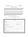
LIMITED PRODUCT WARRANTY
PARA SYSTEMS, INC. (PARA SYSTEMS) warrants that this product will be free from defective material and
workmanship for a period of two years from the date of the original retail purchase by the end user provided
that the warranty registrations card is completed and returned PARA SYSTEMS within ten (10) days of
purchase. PARA SYSTEMS or its designated representative will repair, or at PARA SYSTEMS' option,
replace any product that has been returned by the purchaser and is confirmed by PARA SYSTEMS to be
defective.
Fuses and damage from lightning and over-voltage in excess of specification are not warranted and are the
customer's responsibility. This warranty shall be null and void if this product has been altered, opened
without authorization, misused or damaged by accident, misapplication, abuse, fire, flood or other disaster.
PARA SYSTEMS SHALL NOT BE LIABLE FOR DIRECT, INDIRECT, INCIDENTAL, CONSEQUENTIAL,
OR OTHER TYPES OR DAMAGES RESULTING FROM THE USE OF THIS PRODUCT OTHER THAN
THE LIABILITY STATED ABOVE. THIS WARRANTY IS IN LIEU OF ANY OTHER WARRANTIES
EXPRESSED OR IMPLIED, INCLUDING BUT NOT LIMITED TO, THE IMPLIED WARRANTIES OF
MECHANTABILITY OR FITNESS FOR A PARTICULAR PURPOSE.
PLEASE KEEP THIS DOCUMENT FOR YOUR RECORDS
Model # _______________________ Date Purchased __________________________
Warranty Registration
Model # _________________________ Serial # _________________________
Dealer Name _____________________________________________________
City/State __________________________________ Zip __________________
Protected Equipment _______________________Date Purchased ___________
Your Name _______________________________________________________
Your Company's Name (if applicable) __________________________________
Address _________________________________________________________
City/State __________________________________ Zip __________________
Your Telephone # (______) __________________________________________
This registration must be returned within ten (10) days after purchase to PARA SYSTEMS, INC. or the warranty is not valid.
12