1
FJ-600
*
FJ-500
*
FJ-400
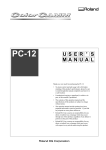
USER'S MANUAL
* This User's Manual is intended for FJ-600, FJ-500 and FJ-400.
Thank you very much for purchasing the FJ-600/500/400.
• To ensure correct and safe usage with a full understanding of this product's performance,
please be sure to read through this manual completely and store it in a safe location.
• Unauthorized copying or transferral, in whole or in part, of this manual is prohibited.
• The contents of this operation manual and the specifications of this product are subject to
change without notice.
• The operation manual and the product have been prepared and tested as much as possible.
If you find any misprint or error, please inform us.
• Roland DG Corp. assumes no responsibility for any direct or indirect loss or damage which
may occur through use of this product, regardless of any failure to perform on the part of
this product.
• Roland DG Corp. assumes no responsibility for any direct or indirect loss or damage which
may occur with respect to any article made using this product.
For the USA
FEDERAL COMMUNICATIONS COMMISSION
RADIO FREQUENCY INTERFERENCE
STATEMENT
This equipment has been tested and found to comply with the
limits for a Class A digital device, pursuant to Part 15 of the
FCC Rules.
These limits are designed to provide reasonable protection
against harmful interference when the equipment is operated
in a commercial environment.
This equipment generates, uses, and can radiate radio
frequency energy and, if not installed and used in accordance
with the instruction manual, may cause harmful interference
to radio communications.
Operation of this equipment in a residential area is likely to
cause harmful interference in which case the user will be
required to correct the interference at his own expense.
NOTICE
Grounding Instructions
Do not modify the plug provided - if it will not fit the outlet,
have the proper outlet installed by a qualified electrician.
Check with qualified electrician or service personnel if the
grounding instructions are not completely understood, or if in
doubt as to whether the tool is properly grounded.
Use only 3-wire extension cords that have 3-prong
grounding plugs and 3-pole receptacles that accept the tool’s
plug.
Repair or replace damaged or worn out cord immediately.
Unauthorized changes or modification to this system can void
the users authority to operate this equipment.
The I/O cables between this equipment and the computing
device must be shielded.
For Canada
CLASS A
NOTICE
This Class A digital apparatus meets all requirements of the
Canadian Interference-Causing Equipment Regulations.
CLASSE A
AVIS
Cet appareil numérique de la classe A respecte toutes les
exigences du Règlement sur le matériel brouilleur du
Canada.
ROLAND DG CORPORATION
1-6-4 Shinmiyakoda, Hamamatsu-shi, Shizuoka-ken, JAPAN 431-2103
MODEL NAME
: See the MODEL given on the rating plate.
RELEVANT DIRECTIVE : EC MACHINERY DIRECTIVE (89/392/EEC)
EC LOW VOLTAGE DIRECTIVE (73/23/EEC)
EC ELECTROMAGNETIC COMPATIBILITY DIRECTIVE (89/336/EEC)
WARNING
This is a Class A product. In a domestic environment this product may cause radio interference in which
case the user may be required to take adequate measures.
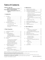
Table of Contents
To Ensure Safe Use .......................................... 2
Pour
About the Labels Affixed to the Unit .... 4
utiliser en toute sécurité .................... 5
À propos des étiquettes collées sur
l'appareil ..................................................... 8
3 Maintenance
3-1
3-2
3-3
1 Introduction
1-1
1-2
Part Names ......................................................... 9
Front View .................................................. 10
Rear View .................................................. 10
Side View ................................................... 11
Inside the Front Cover ................................ 11
Operation Panel .......................................... 12
Making the Connections .................................. 13
Connecting the Power Cord ........................ 13
Connecting the Cable ................................. 14
When You're Finished Making the
Connections ................................................ 15
3-4
3-5
3-6
3-7
3-8
4 User's Reference
4-1
2 Basic Operation
2-1
2-2
2-3
2-4
2-5
2-6
2-7
Installing Ink Cartridges ................................... 16
Powerup ............................................................ 20
Loading the Material ........................................ 21
Loading Roll Material ................................ 22
Loading Sheet Material .............................. 24
When Loading Material Prone to Warping ... 25
Test Printing ..................................................... 26
Printing ............................................................. 27
About Roland COLORCHOICE® .............. 27
Downloading Printing Data ........................ 27
Setting the Printing Mode ........................... 30
Printing at the Desired Location ................. 32
Making Corrections for Printing ................ 36
Ending Printing Operations .............................. 38
Remove the Material .................................. 38
Separating the Printed Portion .................... 38
When Not in Use... ........................................... 40
Power Off in Daily Operation .................... 40
When Not in Use for a Prolonged Period... 41
Replacing the Ink Cartridges ............................ 42
Checking the Remaining Ink Level .................. 44
Cleaning the Printing Heads ............................. 44
If Drop-out Persists Even After Carrying Out
Cleaning Several Times .............................. 45
If Performing Cleaning Several Times at the
[POWERFUL] Menu Does Not Correct the
Drop-out Problem ....................................... 46
Using the Cleaning Kit to Clean the Printing
Heads .......................................................... 46
Changing the Type of Ink ................................. 57
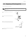
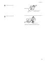
Disposing of Discharged Ink ............................ 59
How to Replace the Separating Knife .............. 60
Cleaning ........................................................... 62
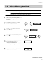
When Moving the Unit... .................................. 63
4-2
4-3
4-4
4-5
4-6
4-7
4-8
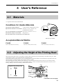
Materials ........................................................... 65
Conditions for Usable Materials ................. 65
Acceptable Material Widths ....................... 65
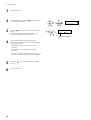
Adjusting the Height of the Printing Head ....... 65
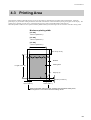
Printing Area .................................................... 67
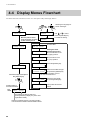
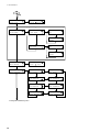
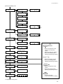
Display Menus Flowchart ................................ 68
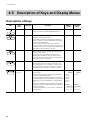
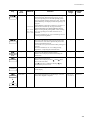
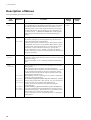
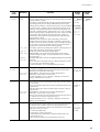
Description of Keys and Display Menus ......... 72
Description of Keys .................................... 72
Description of Menus ................................. 74
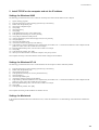
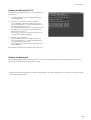
Network Connection ........................................ 77
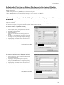
How to View the Manuals (PDF Files) ...... 77
Setup ........................................................... 78
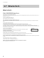
What to Do If... ................................................ 84
What to Do If... ........................................... 84
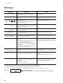
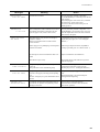
Messages ..................................................... 92
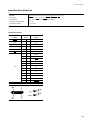
Specifications ................................................... 94
Windows® and Windows NT® are registered trademarks or trademarks of Microsoft® Corporation in the United States and/or other countries.
IBM is a registered trademark of International Business Machines Corporation.
Macintosh is a registered trademark or trademark of Apple Computer, Inc. in the USA and other countries.
Adobe, PostScript and Acrobat are trademarks of Adobe Systems Incorporated.
Netscape and Netscape Navigator are registered trademarks of Netscape Communications Corporation in the United States and/or other countries.
COLORCHOICE® is a registered in the U.S. Patent Office.
Other company names and product name are trademarks or registered trademarks of their respective holders.
Copyright © 2001 Roland DG Corporation
http://www.rolanddg.com/
1
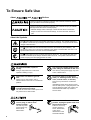
To Ensure Safe Use
About
and
Notices
Used for instructions intended to alert the user to the risk of death or severe
injury should the unit be used improperly.
Used for instructions intended to alert the user to the risk of injury or material
damage should the unit be used improperly.
* Material damage refers to damage or other adverse effects caused with
respect to the home and all its furnishings, as well to domestic animals or
pets.
About the Symbols
The
symbol alerts the user to important instructions or warnings. The specific meaning of
the symbol is determined by the design contained within the triangle. The symbol at left means
"danger of electrocution."
The
symbol alerts the user to items that must never be carried out (are forbidden). The
specific thing that must not be done is indicated by the design contained within the circle. The
symbol at left means the unit must never be disassembled.
The
symbol alerts the user to things that must be carried out. The specific thing that must
be done is indicated by the design contained within the circle. The symbol at left means the
power-cord plug must be unplugged from the outlet.
Do not disassemble, repair, or
modify.
Use only with a power supply of the
same rating as indicated on the unit.
Doing so may lead to fire or abnormal
operation resulting in injury.
Use with any other power supply may lead
to fire or electrocution.
Ground the unit with the ground
wire.
Do not use while in an abnormal
state (i.e., emitting smoke, burning
odor, unusual noise, or the like).
Failure to do so may result in risk of
electrical shock in the even of a mechanical
problem.
Use only with the power cord
included with this product.
Use with other than the included power cord
may lead to fire or electrocution.
2
Doing so may result in fire or electrical
shock.
Immediately switch off first the sub power,
then the main power, unplug the power cord
from the electrical outlet, and contact your
authorized Roland DG Corp. dealer or
service center.
Do not use with a damaged power
cord or plug, or with a loose
electrical outlet.
When not in use for extended
periods, unplug the power cord from
the electrical outlet.
Use with any other
power supply may
lead to fire or
electrocution.
Failure to do so may
result in danger of
shock, electrocution,
or fire due to
deterioration of the
electrical insulation.
Do not injure or modify the electrical
power cord, nor subject it to
excessive bends, twists, pulls,
binding, or pinching, nor place any
object of weight on it.
When unplugging the electrical
power cord from the power outlet,
grasp the plug, not the cord.
Unplugging by pulling the cord may damage
it, leading to fire or electrocution.
Doing so may
damage the
electrical power
cord, leading to
electrocution or
fire.
Do not attempt to unplug the power
cord with wet hands.
Do not allow liquids, metal objects
or flammables inside the machine.
Doing so may
result in electrical
shock.
Such materials
can cause fire.
Unpacking, installation, and moving
must be carried out by four or more
persons.
Use the joining screws to secure the
unit to the stand.
Otherwise the machine or the stand may
fall, resulting in injury.
(The total weight
of the package is
176 kg (388 lb.) for
the FJ-600, 166 kg
(365.9 lb.) for the
FJ-500, and 154
kg (339.5 lb.) for
the FJ-400.)
Install in a level and stable location.
Otherwise the unit may tip over and cause
injury.
Failure to do so
may result in
falling of the unit,
leading to injury.
Use care to avoid pinching the
fingers when placing the unit on the
stand.
Doing so may
result in injury.
Load roll material at the proper
position.
Release the caster locks for the
stand before attempting to move.
Otherwise the roll may
fall, resulting in injury.
Otherwise the unit may tip over and cause
injury.
Do not touch the tip of the
separating knife with your fingers.
Make sure the power to the unit is
off before attempting to replace the
separating knife.
Doing so may result in injury.
Doing so may result in injury.
3
Do not place hands within the space
to the front of the unit while in
operation.
If ink contacts the eyes, flush
immediately with water.
Doing so may
result in injury.
When closing the front cover, be
careful not to pinch your fingers.
Store ink cartridges out of the reach
of children.
Doing so may result in injury.
About the Labels Affixed to the Unit
These labels are affixed to the body of this product.
The following figure describes the location and
content of these messages.
When closing the
front cover, be
careful not to pinch
your fingers.
Do not place hands
within the space to
the front of the unit
while in operation.
Ink cartridge
Model name
Rating label
Use a rated power
supply.
In addition to the
NOTICE
and
symbols, the symbols shown below are also used.
: Indicates information to prevent machine breakdown or malfunction and ensure correct use.
: Indicates a handy tip or advice regarding use.
4
Do not dismantle the
cartridge.
Keep out of reach of children.
Do not store the cartridge in
high or freezing
temperatures.
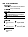
Pour utiliser en toute sécurité
Avis sur les avertissements
Utilisé pour avertir l'utilisateur d'un risque de décès ou de blessure grave en
cas de mauvaise utilisation de l'appareil.
Utilisé pour avertir l'utilisateur d'un risque de blessure ou de dommage
matériel en cas de mauvaise utilisation de l'appareil.
* Par dommage matériel, il est entendu dommage ou tout autre effet
indésirable sur la maison, tous les meubles et même les animaux
domestiques.
À propos des symboles
Le symbole
attire l'attention de l'utilisateur sur les instructions importantes ou les
avertissements. Le sens précis du symbole est déterminé par le dessin à l'intérieur du triangle.
Le symbole à gauche signifie "danger d'électrocution".
Le symbole
avertit l'utilisateur de ce qu'il ne doit pas faire, ce qui est interdit. La chose
spécifique à ne pas faire est indiquée par le dessin à l'intérieur du cercle. Le symbole à
gauche signifie que l'appareil ne doit jamais être démonté.
Le symbole
prévient l'utilisateur sur ce qu'il doit faire. La chose spécifique à faire est
indiquée par le dessin à l'intérieur du cercle. Le symbole à gauche signifie que le fil électrique
doit être débranché de la prise.
Ne pas démonter, réparer ou
modifier.
Le non-respect de cette consigne pourrait
causer un incendie ou provoquer des
opérations anormales entraînant des
blessures.
Mettre l'appareil à la masse avec une
prise de terre.
Le non-respect de cette consigne pourrait
entraîner des décharges
électriques en
cas de problème mécanique.
N'utilisez que le cordon
d'alimentation fourni avec ce
produit.
L’utilisation avec un autre cordon
d’alimentation que celui fourni pourrait
entrainer un risque d’incendie ou
d’électrocution.
Utiliser seulement avec une
alimentation de mêmes
caractéristiques électriques que
celles indiquées sur l'appareil.
Une négligence à ce niveau pourrait
provoquer un incendie ou une
électrocution.
Ne pas utiliser si l'appareil est dans
un état anormal (c'est-à-dire s'il y a
émission de fumée, odeur de brûlé,
bruit inhabituel etc.).
Le non-respect de cette consigne pourrait
provoquer un incendie ou des décharges
électriques.
Couper immédiatement l'alimentation
secondaire et ensuite l'alimentation
principale. Débranchez le fil électrique et
contacter votre revendeur ou votre centre
de service de la société Roland DG
autorisé.
5
Ne pas utiliser avec une fiche ou un
fil électrique endommagé ou avec
une prise mal fixée.
Débrancher le fil lorsque l'appareil
reste inutilisé pendant une longue
période.
Une négligence à
ce niveau pourrait
provoquer un
incendie ou une
électrocution.
Une négligence à ce niveau pourrait
provoquer des décharges électriques,
une électrocution ou
un incendie dû à une
détérioration de
l'isolation électrique.
Ne pas endommager ou modifier le
fil électrique. Ne pas le plier, le
tordre, l'étirer, l'attacher ou le serrer
de façon excessive. Ne pas mettre
d'objet ou de poids dessus.
Saisir la fiche et non le fil électrique
lorsque vous débranchez.
Débrancher en tirant sur le fil pourrait
l'endommager et risquer de provoquer un
incendie ou une électrocution.
Une négligence à
ce niveau pourrait
endommager le fil
électrique ce qui
risquerait de
provoquer une
électrocution ou un
incendie.
Ne pas essayer de débrancher le fil
avec des mains mouillées.
Une négligence à
ce niveau pourrait
provoquer des
décharges
électriques.
Le déballage, l’installation et le
déplacement de l’appareil doivent
être effectués par quatre personnes
ou plus.
Le non-respect de cette consigne pourrait
causer des défauts dans l’appareil
entraînant des blessures.
(Le poids total
de la boîte
emballée est
176 kg [FJ-600],
166 kg [FJ-500]
ou
154 kg [FJ-400].)
Installer dans un endroit stable et de
niveau.
Sinon l'appareil pourrait se renverser et
provoquer des blessures.
Ne pas introduire de liquide, d'objet
métallique ou inflammable dans
l'appareil.
Ce genre de
matériel peut
provoquer un
incendie.
Utiliser les vis fournies pour bien
fixer l'appareil sur le support.
Le non-respect de
cette consigne
pourrait causer des
défauts dans
l'appareil entraînant
des blessures.
Manipuler avec précaution pour
éviter de se coincer les doigts lors
de l'installation de l'appareil sur le
support.
Une négligence à
ce niveau pourrait
provoquer des
blessures.
6
Le rouleau doit être placé à une
position adéquate.
Une négligence à ce
niveau pourrait
provoquer la chute du
rouleau et causer des
blessures.
Ne pas toucher le bout de la lame
séparatrice avec les doigts.
Une négligence à ce niveau pourrait
provoquer des blessures.
Ne pas mettre les mains dans
l'espace du devant quand l'appareil
est en marche.
Débloquer le mécanisme d'arrêt des
roulettes du support avant de le
déplacer.
Sinon l'appareil pourrait se renverser et
provoquer des blessures.
S'assurer que l'appareil est hors
tension avant d'essayer de
remplacer la lame séparatrice.
Une négligence à ce niveau pourrait
provoquer des blessures.
Si de l'encre entre en contact avec
les yeux, rincer immédiatement à
l'eau.
Une négligence à ce niveau pourrait
provoquer des blessures.
Manipuler avec précaution pour
éviter de se coincer les doigts lors
de la fermeture du couvercle de
devant.
Ranger les cartouches d'encre hors
de portée des enfants.
Une négligence à ce niveau pourrait
provoquer des blessures.
7
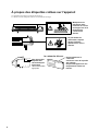
À propos des étiquettes collées sur l'appareil
Ces étiquettes sont collées à l'extérieur de l'appareil.
Les dessins suivants indiquent l'endroit et le contenu des messages.
Manipuler avec
précaution pour
éviter de se coincer
les doigts lors de la
fermeture du
couvercle de
devant.
Ne pas mettre les
mains dans l'espace
devant l'élément
quand celui-ci est en
marche.
la cartouche d'encre
Nom du modèle
Étiquette des
caractéristiques
électriques
Utiliser l'alimentation
appropriée
8
Ne pas démonter la
cartouche.
Conserver hors de la portée
des enfants.
Ne pas emmagasiner á das
températures hautes ou
basses.
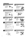
1 Introduction
1 Introduction
* In this manual, sections that explain commons points for the FJ-600/500/400 use only illustrations of the FJ-500. Some details of the
FJ-600 or FJ-400 differ from the figure.
1-1 Part Names
NOTICE
If you will leave the printing head being uncapped for a long time (for example, open the front cover while
printing is made on the middle of platen), printing heads may get clogging and, in some case it results unrecoverable damage to the printing head.
Do not touch the Y rail or the inner side of the right cover.
Touching the area shown may cause the fingers to be soiled by grease or ink, and may result in diminished
image quality.
Entire Y-rail portion
Do not put hands inside
9
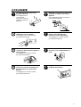
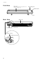
1 Introduction
Front View
Front cover
If the cover is opened while in operation, it will
execute an emergency stop.
Sheet loading lever
Operation panel
Cover
Rear View
Ink cartridge ports
Media cover
Drain bottle
Parallel connector
RJ-45 (Ethernet) connector
10
1 Introduction
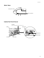
Side View
Main power switch
Power connector
Inside the Front Cover
Carriage
When not printing, this stays inside the cover.
Platen
Knife guide
Guide lines
Reflective tape
Grit roller
Pinch roller
11
1 Introduction
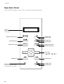
Operation Panel
For more information about the keys, take a look at "4-5 Description of Keys and Display Menus".
Display
This show the various setting menus,
and messages.
[PRINT QUALITY] key
SETUP LED
[SETUP] key
[CLEANING] key
PAUSE LED
[PAUSE] key
[SHEET CUT] key
BASE POINT LED
[BASE POINT] key
Arrow key
([ ] [ ] [
[MENU] key
BUSY LED
This flashes while data is being
received from the host computer.
12
[ENTER] key
POWER LED
[POWER] key
] [
])
1 Introduction
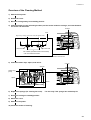
1-2 Making the Connections
Use only with a power supply of the
same rating as indicated on the unit.
Ground the unit with the ground
wire.
Use with any other power supply may lead
to fire or electrocution.
Failure to do so may result in risk of
electrical shock in the even of a mechanical
problem
Use only with the power cord
included with this product.
Use with other than the included power cord
may lead to fire or electrocution.
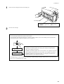
NOTICE
Before connecting the cable, make sure the computer's power and the FJ-600/500/400's main power switch are
switched off.
Securely connect the power cord, computer I/O cable and so on so that they will not be unplugged and cause
failure during operation. Doing so may lead to faulty operation or breakdown.
Arrange the power cord and interface connection cable to prevent tripping when moving around the unit.
Pass the cable through the established location, making sure that it does not touch the loaded material.
If the cable touches the material during printing, material feed may be obstructed, resulting in poor printing
accuracy.
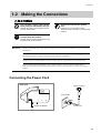
Connecting the Power Cord
Side View
Power connector
Power outlet
Power Connector
Power cord
13
1 Introduction
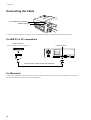
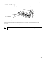
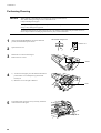
Connecting the Cable
RJ-45 (Ethernet) connector
Parallel connector
* Cables are available separately. One which you are sure matches the model of computer being used should be selected.
For IBM PC or PC compatibles
Parallel connector
Secure the cable in place with the clips.
Parallel connector
Parallel interface cable (compliant with IEEE1284)
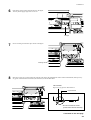
For Macintosh
Connection to a Macintosh requires optional items such as an expansion card or special cable. For more information on the required
optional items and connection settings, contact a Roland dealer.
14
1 Introduction
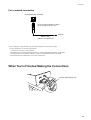
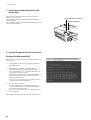
For a network connection
RJ-45 (Ethernet) connector
*Do not connect a telephone cable to
the RJ-45 (Ethernet) connector.
Ethernet
Network cable
(10Base-T or 100Base-TX)
* Various settings are required when using the FJ-600/500/400 in a network environment.
For more information, see the following materials.
- "4-6 Network Connection" in this document
- "Roland-PrintServer Installation Manual" (PDF file), on the included Roland-PrintServer CD-ROM
- "Roland-PrintServer User Manual" (PDF file), on the included Roland-PrintServer CD-ROM
- "Roland-PrintServer for Macintosh Users" on the separate sheet
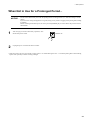
When You're Finished Making the Connections
Pass the cable through here.
15
2 Basic Operation
2 Basic Operation
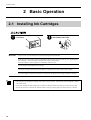
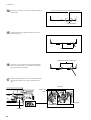
2-1 Installing Ink Cartridges
Store ink cartridges out of the reach
of children.
NOTICE
If ink contacts the eyes, flush
immediately with water.
Do not remove any ink cartridges except when shipping the FJ-600/500/400.
If ink runs out, replace with a special ink cartridge of the same type and color of ink (see "3-1 Replacing the
Ink Cartridges"). Do not attempt to refill and reuse an empty ink cartridge.
If an ink cartridge is removed, replace it immediately with a new one.
Do not attempt to disassemble an ink cartridge.
Unused ink cartridges should be stored unopened at a temperature of -20°C (-4°F) to 40°C (104°F).
If an ink cartridge is dropped, the shock due to the fall may damage the ink cartridge and make it unusable.
- If any ink gets on your hands or clothing, wash it off as soon as possible. Ink stains may become difficult to remove
if allowed to stand.
- Once an ink cartridge has been installed, do not remove it until the ink has been used up. Frequent insertion and
removal may allow air to enter the ink tube and result in a drop in printing quality due to dot drop-out or the like.
16
2 Basic Operation
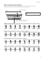
Before You Install the Ink Cartridges
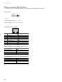
Choose the plate mounting surface of the ink-cartridge port that matches the ink color of the cartridge you are installing.
If the plate surface on the left side is changed, the ink cartridge that you can install also changes.
Ink cartridge ports
PIGMENT = pigmented ink
DYE = dye-based ink
When inserting the cartridge, make sure that it is
inserted into the correct slot for that color.
PIGMENT 8COLOR (Pigmented ink : orange, green, light cyan, light magenta, black, cyan, magenta, and yellow)
PIGMENT
Orange
PIGMENT
Green
PIGMENT
Light cyan
PIGMENT
Light magenta
PIGMENT
Black
PIGMENT
Cyan
PIGMENT
Magenta
PIGMENT
Yellow
PIGMENT
Cyan
PIGMENT
Magenta
PIGMENT
Yellow
DYE
Cyan
DYE
Magenta
DYE
Yellow
PIGMENT 4COLOR (Pigmented ink : black, cyan, magenta, and yellow)
PIGMENT
Black
PIGMENT
Cyan
PIGMENT
Magenta
PIGMENT
Yellow
PIGMENT
Black
DYE 4COLOR (Dye-based ink : black, cyan, magenta, and yellow)
DYE
Black
DYE
Cyan
DYE
Magenta
DYE
Yellow
DYE
Black
PIGMENT & DYE 4 (Pigmented ink : black, cyan, magenta, and yellow), (Dye-based ink : black, cyan, magenta, and yellow)
DYE
Black
DYE
Cyan
DYE
Magenta
DYE
Yellow
PIGMENT
Black
PIGMENT
Cyan
PIGMENT
Magenta
PIGMENT
Yellow
17
2 Basic Operation
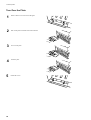
Turn Over the Plate
1
Remove the two screws shown in the figure.
2
Pull out the plate toward the front of the machine.
3
Turn over the plate.
4
Insert the plate.
5
18
Attach the screws.
2 Basic Operation
Install the Ink Cartridges
Insert each ink cartridge into the corresponding ink-cartridge port. Insert it firmly, as far as it will go.
PIGMENT = Pigmented ink
DYE = Dye-based ink
Before you insert a cartridge, make sure the ink color matches the slot where it is to be inserted.
When you have finished installing the ink cartridges, make the settings on the machine for the type of ink to match the installed inks.
You can make the setting for the ink type when you switch on the power for the first time, or when you switch on the power after
removing ink.
For more information, see the next section, "2-2 Powerup."
When you switch on the power for the first time, or when you switch on the power after removing ink, ink-filling is
performed. This operation takes several minutes.
19
2 Basic Operation
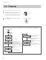
2-2 Powerup
Be sure to mount the drain bottle before turning on the power.
1
When you're using the machine for the first time, turn on
the main power switch on the side of the unit.
Switch to "I"
* Leave the main power switch on, and in daily use, use
the sub power switch to turn the power on and off.
2
Press the [POWER] key (the sub power switch) on the
operation panel.
The POWER LED lights up
When the power is turned on for the first time, or turned on after removing the ink
The POWER LED lights up
Roland FJ-500
Ver.1.00
Roland FJ-500
INK NOT FILLED
RAISE THE HEAD
20
SELECT INK TYPE
PIGMENT 8COLOR
No ink is filled.
Make the setting for the initial
head-height position.
Refer to "4-2 Adjusting the
Height of the Printing Head" and
move the lever to the "2 (High)"
position.
LOWER THE HEAD
Move the lever to the "1 (Low)"
position.
LOWER THE HEAD
Press the [ENTER] key.
Select the installed ink type and
press the [ENTER] key.
PIGMENT 8COLOR / PIGMENT 4COLOR / DYE
4COLOR / PIGMENT & DYE 4
INSTALL
DRAIN TANK
Attach the drain bottle and press the
[ENTER] key.
FILLING INK...
Ink-filling is performed.
This operation takes several minutes.
2 Basic Operation
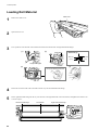
2-3 Loading the Material
NOTICE
Load roll material at the proper
position.
When closing the front cover, be
careful not to pinch your fingers.
Otherwise the roll may
fall, resulting in injury.
Doing so may result in injury.
Before loading roll material, be sure to install the media guide.
- When transparent material is loaded, it is necessary to set [SHEET TYPE] to [CLEAR]. For more information, see
"4-7 What to Do If..." ( [SHEET SET ERROR SET AGAIN] appears and the material cannot be detected even
when the [SETUP] key is pressed).
- When loading thicker material or material that is prone to warping, it may be necessary to adjust the head height.
For more information, see "4-2 Adjusting the Height of the Printing Head."
- When changing to a different type of material, it may be necessary to perform feed correction or bidirectional
correction. For more information, see "2-5 Printing -- Making Corrections for Printing."
- When the left or right edges of the material are warped, use the media clamps. Performing printing without using the
media clamps may result in scraping of the heads or jammed material. Scraping of the heads and jammed material
may damage or soil the printing heads, resulting in poorer printing accuracy. Do not use material that is so strongly
warped that the media clamps are lifted.
Acceptable material widths
FJ-600
210 to 1625 mm (8-5/16 to 64 in.)
FJ-500
210 to 1371 mm (8-5/16 to 54 in.)
FJ-400
210 to 1117 mm (8-5/16 to 44 in.)
21
2 Basic Operation
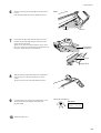
Loading Roll Material
Media cover
1
Remove the media cover.
2
Open the front cover.
3
Line up with the core diameter of the loaded roll material and refit the left- and right-hand media flanges.
(2)
(1)
Media flange
Media flange
50.8 mm
(2 in.)
76.2 mm
(3 in.)
Flange retaining pin
(3)
(4)
Line up the ridges and grooves.
4
Fit the hole on the left side of the roll material all the way onto the left-hand media flange.
5
Fit the right-hand media flange all the way into the hole on the right-hand side of the roll material, and tighten the retainer screw
to secure in place.
Left-hand media flange
22
Roll material
Right-hand media flange
2 Basic Operation
6
Pass the end of the material through the unit from back
to front.
Pull out material until the sensor is hidden from view.
Front
Material
7
Sensor
Grasp the front edge of the material at the front of the
machine and turn the media flanges at the back of the
unit to roll back the media.
When you roll back the material until the sensor comes
into view, a tight seal is formed between the material and
the platen, and the material is stretched taut.
Entire material
stretched taut
Sensor
8
With the material pulled out from the roll stretched taut
with no slack, move the sheet loading lever toward
LOAD.
The pinch rollers lower to hold the material in place.
9
Close the front cover, and press the [SETUP] key. This
detects the width of the material and displays the
printable width.
10
The SETUP LED lights up
Top menu
W 1234 mm
NORMAL
BI-DIR
Attach the media cover.
23
2 Basic Operation
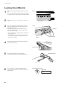
Loading Sheet Material
1
Remove the left-hand media flange at the back of the
unit.
Move the right-hand media flange at the back of the unit
to a position where it does not touch the loaded material.
2
Pass the material between the pinch rollers and the grit
rollers.
3
Line up the right-hand side of the material with the
guide line, and line up the front edge of the material
with the reflective tape.
If the front edge of the material has been cut at an
angle, pull out the material so that all of the material
covers the reflective tape.
* Be sure to line up the right-hand edge of the material
with the guide line.
If the material is not positioned correctly when you
press the [SETUP] key, the message "SET AGAIN"
appears on the display.
4
Front
Sheet material
Front
Guide line
Reflective tape
Material
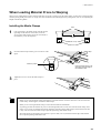
Drape the pulled-out portion at the back between the
unit and the media guide.
Media guide
5
Move the sheet loading lever toward LOAD.
The pinch rollers lower to hold the material in place.
6
Close the front cover, and press the [SETUP] key.
This detects the width of the material and displays the
printable width.
24
Sheet loading lever
The SETUP LED lights up
Top menu
W 300 mm
NORMAL
BI-DIR
2 Basic Operation
When Loading Material Prone to Warping
When you are loading material whose left and right edges are prone to warping, use the media clamps. At such times, perform printing
with the printing heads positioned at "2" (high). For more information about the height of the printing heads, refer to "4-2 Adjusting the
Height of the Printing Head."
Installing the Media Clamps
Holes
1
Line up the holes in the media clamps with the left and
right edges of the material. At this time, loosen the
screws on the media clamps, but do not loosen them so
much that they come off completely.
Material
Media clamps
Screws
2
Media clamp
Insert the media clamps into the grooves as shown in the
figure.
Material
Groove
Insert this portion.
Insert the media clamp in the
same way at the left edge of
the material as well.
3
Tighten the screws to secure the media clamps in
place.
Screw
- When you are using the media clamps, attempting to cut off the material causes the material to come loose from the
media clamps. If this happens, reinstall the media clamps.
- When you are not using the media clamps, remove them from the FJ-600/500/400.
- As printing proceeds, the material may move to the left right and touch or come loose from the media clamps. After
about 1 m (39-3/8 in.) of material has been fed, check the positioning of the media clamps. If the material looks like
it may come loose from the media clamps, adjust the positioning of the media clamps.
- The media clamps are designed to press down on a space 10 mm (7/16 in.) inward from either edge of the material.
Do not perform printing within these areas.
25
2 Basic Operation
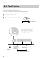
2-4 Test Printing
Before starting to print, carry out a Test print to check the state of the head.
Problems such as missing dots may reduce the printing quality.
If the test results show a problem, carry out head cleaning to restore the head to its normal state.
1
2
Load a material, then close the front cover.
Press the [CLEANING] key to execute [TEST PRINT].
CLEANING
TEST PRINT
Press the [ENTER] key to
print a test pattern.
If there are any missing dots or other evidence
of a drop in printing quality, clean the head.
For more information about head cleaning, see
"3-3 Cleaning the Printing Heads."
If there is dot drop-out on
this side, then for
[CLEANING], choose
[LEFT HEAD].
If there is dot drop-out on this side,
then for [CLEANING], choose
[RIGHT HEAD].
Direction of material
discharge
If there is dot drop-out in both areas, then for
[CLEANING], choose [BOTH HEADS].
26
2 Basic Operation
2-5 Printing
NOTICE
Opening the front cover while printing is in progress causes an emergency stop. This means that printing may
not be carried out correctly even if operation is resumed, due to drop-out or misalignment of the image.
To pause printing for any other reason than an emergency stop, press the [PAUSE] key.
Note pressing the [PAUSE] key to pause operation may result in differing image quality before and after the
pause. It is a good idea to avoid pausing operation while printing is in progress whenever possible.
If you will leave the printing head being uncapped for a long time (for example, open the front cover while
printing is made on the middle of platen), printing heads may get clogging and, in some case it results unrecoverable damage to the printing head.
Do not use the [ ] key to return a portion of the material that's already been printed. The pinch rollers may
pass over the printed surface, smudging the ink.
Also, do not use the [ ] and [ ] keys to feed and return unprinted portions many times. The grit rollers
may make tracks on the material, resulting in poor printing precision.
During printing, do not touch the portion of the material that's already been discharged.
Doing so may obstruct material feed or cause the material to rub against the heads, which may result in a paper
jam or damage to the heads.
About Roland COLORCHOICE®
The included Roland COLORCHOICE® is a software raster image processor, or RIP. It takes printing data such as a PostScript file
received from a program, performs raster image processing on the computer, and outputs the data to the FJ-600/500/400.
(Raster image processing converts images and text in a format such as PostScript to bitmap data.)
For more information about Roland COLORCHOICE®, see the Roland COLORCHOICE® User's Manual with the machine.
Downloading Printing Data
Printing is started when data is sent.
If the top menu isn't displayed, printing doesn't start even when
data is sent from the computer.
Conditions for starting printing
The material must be already set up (with the SETUP LED
lighted),
and the display must show the top menu.
Top menu
W 1234 mm
NORMAL
BI-DIR
If another menu screen is displayed, press the [SETUP] key to
go back to the top menu.
(Pressing the [SETUP] key when another menu screen is
displayed does not cancel the set-up for the material.)
27
2 Basic Operation
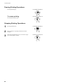
Pausing Printing Operations
Press the [PAUSE] key.
The PAUSE LED lights up
To resume printing
The PAUSE LED goes out
Press the [PAUSE] key again.
Stopping Printing Operations
1
Press the [PAUSE] key.
2
Halt transmission of printing instructions from the
computer.
3
Hold down the [SETUP] key for one second or longer.
Any remaining data is cleared.
28
The PAUSE LED lights up
The SETUP LED goes out
2 Basic Operation
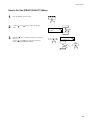
If ink runs out during printing
If ink runs out during printing, a warning beep sounds and the screen shown in the figure appears.
Replace the ink cartridge.
Ignoring the message and continuing printing without replacing the ink may adversely affect image quality, resulting in faintness or other
problems.
O___G
K __C
_c
M
_m _
Y __
The "___" for the ink that has run out flashes.
The letter indicates the color of the ink.
O = Orange, G = Green, c = Light Cyan,
m = Light Magenta, K = Black, C = Cyan,
M = Magenta , Y = Yellow
The " " symbols are a guide to the amount of
remaining ink.
The displayed inks indicate the ink cartridges
at the locations shown in the figure.
O___G
K __C
_c
M
_m _
Y __
In the preceding example, the ink type is
[PIGMENT 8COLOR].
For [PIGMENT 4COLOR], [DYE 4COLOR],
or [PIGMENT & DYE 4], "KCMY" is displayed
instead of "OGcm."
1
When [INK CONTROL]'s [EMPTY MODE] is set to
[LATER]
1) Press any key on the control panel to display the top
menu.
2) Press the [PAUSE] key to pause printing.
The PAUSE LED lights up
When [INK CONTROL]'s [EMPTY MODE] is set to
[PROMPT]
The unit pauses automatically.
When you replace the ink cartridge, resume printing.
2
Pull out the cartridge for the ink color that has run out,
and replace with a new cartridge (see "3-1 Replacing
the Ink Cartridges").
3
Press the [PAUSE] key to resume printing.
The PAUSE LED goes out
About the [EMPTY MODE]
When replacement of the ink cartridge becomes necessary while printing is in progress, this setting determines whether printing
continues or pauses.
This setting is used when the ink cartridge cannot be changed immediately during printing, such as during unattended operation at night.
[LATER] causes printing to continue without pause even if ink refilling becomes necessary. Printing continues with the small amount of
ink remaining, so the printed image may become faint as the ink runs out. In general, it should possible to perform about 1 m2 (10 ft2) of
printing once this message appears, although the actual varies widely according to the amount of ink needed for the particular image.
Printing is continued only for the data currently being printed. Operation stops after one image is output.
[PROMPT] causes operation to pause immediately when the ink cartridge needs to be changed. Printing is resumed by replacing the
cartridge . Please note, however, that the colors of an image in progress may no longer be perfectly matched if the unit is allowed to
remain paused for two or three hours before resuming printing.
29
2 Basic Operation
Setting the Printing Mode
Setting the Printing Mode and Printing Direction
Before start to print, set the printing mode and printing direction.
On the control panel, press the [PRINT QUALITY] key and specify the printing mode and direction of printing.
- When you can make the settings for the printing mode and printing direction on the computer, the computer's
settings take priority.
- The optimal printing mode differs according to the material you are using.
- Printing when using eight-color pigmented ink ([PIGMENT 8COLOR]) is taken as a guide for usage of the various
modes. ([PIGMENT 8COLOR] obtains better image quality than [PIGMENT 4COLOR] or [DYE 4COLOR], but
output times are longer.)
Printing quality, output time, and the amount of data processing in the computer vary according to the printing
mode and the material used. Choose a mode that matches the task.
- The printing time for the same original data becomes increasingly longer in this sequence: DRAFT, NORMAL,
vNORMAL, SUPER, vSUPER and vPHOTO. Also, because the size of the output file grows larger, the processing
time for creating the output file also becomes longer.
It's also necessary to ensure enough memory on the computer.
- When the installed ink type is [PIGMENT 4COLOR] or [DYE 4COLOR] and the printing mode is vNORMAL or
vSUPER, printing using only the printing head on one side is performed in order to improve printing quality. Use
the [HEAD SELECT] menu to select whether to use the left printing head or the right printing head.
Printing Mode
Printing Direction
vPHOTO:
This is suitable for printing photographs with the highest image
quality.
However, because the amount of data becomes large, printing time
is longer.
UNI-DIRECTION:
Unidirectional printing.
Printing is performed as the carriage moves from right to left.
Printing quality is better than with [BI-DIRECTION].
vSUPER:
This is suitable for printing photographs.It's also suitable for
applications such as color proofs.
BI-DIRECTION (factory default):
Bidirectional printing.
Printing is performed as the carriage moves from right to left, and
also as it returns from left to right.
Printing speed is faster than with [UNI-DIRECTION].
vNORMAL:
This is suitable for printing posters and the like.
SUPER:
This is suitable for printing posters and signs at high density. It's
also suitable for printing Clear Pet Film.
NORMAL (Factory default):
This is suitable for printing signs at high density and at
comparatively high speed.
DRAFT:
This is suitable for printing large-size signs. It's also suitable for
applications such as checking layout.
* When you are performing printing from the included Roland COLORCHOICE®, then in addition to the preceding printing modes,
you can also select gNORMAL or sNORMAL. For more information about gNORMAL and sNORMAL, refer to "About Roland
COLORCHOICE® Parameter Settings and ICC Profiles During Output."
30
2 Basic Operation
How to Set the [PRINT QUALITY] Menu
1
Press the [PRINT QUALITY] key.
2
Use the [
mode.
3
Press the [
] key to make the setting for the printing
direction.
Use the [ ] and [ ] keys to display the printing
direction, then press the [ENTER] key.
] and [
] keys to choose the printing
PRINT QUALITY
NORMAL
PRINT QUALITY
BI-DIRECTION
31
2 Basic Operation
Printing at the Desired Location
This sets the location where printing starts.
When [SHEET TYPE] is set to [OPAQUE], the width of the
printing area is set automatically (see "4-3 Printing Area").
To determine the desired printing area, follow the steps in
"Setting the printing area in the left-right direction (the direction
of carriage movement)" to set the width of the printing area.
When [SHEET TYPE] is set to [CLEAR], the printing area is
not set automatically, so set the printing area in the same way. If
this setting is not made, it is set to the default printing area for
the maximum loadable width for the FJ-600/500/400.
Canceling setup cancels the printing area.
Original printing
area
New printing
area
Left-hand edge of the printing area
Right-hand edge of the printing area
Setting the printing area in the left-right direction (the direction of carriage movement)
To change the start point (origin point) for printing, use the
[BASE POINT] key. At this time, the printing area does not
change.
Follow the step in both "Specifying a location in the feed
direction" and "Specifying a location in the left-right direction
(the direction of carriage movement)" to set the start point.
Next printing
* Returning the
start point in
the left-right
direction to its
original
location
Margin (setting on the computer)
Printing area
Start point
(origin point)
Starting location in the
feed direction
Specifying a location in
the feed direction
Starting location in the left-right direction
Specifying a location in the left-right direction (the
direction of carriage movement)
Specifying a location in the feed direction
Knife guide
Use the [ ] and [ ] keys to move the material to the
location where you want to start printing.
In the figure, the next printing operation starts from the
location shown.
* For roll material, when the material has been returned
toward the back of the unit with the [ ] key, manually
roll the material back onto the roll so that all of the
material at the back of the unit is stretched taut.
The next printing operation starts here.
Reflective tape
Front edge of the material
32
Print-start line
2 Basic Operation
Specifying a location in the left-right direction (the direction of carriage movement)
1
Press the [
] key to move the carriage to the present
starting location for printing in the left-right direction.
Starting location for
printing in the left and
right direction
2
Right-hand edge
of the material
Use the [
] and [
] keys to move the marker to the
new print-start position.
Marker
3
Press the [BASE POINT] key.
The BASE POINT LED lights up
To release the starting location that
has been set...
• Set a new starting location in a different location.
• Press the [SETUP] key to cancel the setup for the
material (making the SETUP LED go out).
- If the carriage moves away from the standby position when not printing, problems such as drying-out of the printing heads or dot drop] key to move the carriage, the carriage returns
out during printing may occur. For this reason, about 60 seconds after pressing the [
to the standby position.
Also, the carriage returns to the standby position when about 30 seconds passes during this interval after the [
] and [
] key is
released.
If the setting could not be made in within the time limit, then do the setting over again from the beginning.
- The starting location set by pressing the [BASE POINT] key is released after printing one page.
33
2 Basic Operation
Setting the printing area in the left-right direction (the direction of carriage movement)
* This can be set only at the time of material setup.
1
Press the [MENU] key and [
screen shown in the figure.
2
Press the [
figure.
3
Press the [
] key to display the screen shown in the
figure.
When you do this, the carriage moves to the right edge
of the printing area.
] key to display the
] key to display the screen shown in the
MENU
PRINT AREA
PRINT AREA
RIGHT EDGE
RIGHT EDGE
SET
Right-hand edge of
the printing area
4
Right-hand edge
of the material
Use the [
] and [
] keys to move the marker at the
right edge of the carriage to the location that you want to
make the right edge of the printing area. Press the
[ENTER] key to lock in the setting the right-hand edge
with an audible beep.
Marker
5
Press the [
figure.
6
Press the [
] key to make the following screen
appear on the display.
When you do this, the carriage moves to the left edge
of the printing area.
] key to display the screen shown in the
PRINT AREA
LEFT EDGE
LEFT EDGE
SET
Left-hand edge
of the material
34
Left-hand edge of
the printing area
2 Basic Operation
7
Use the [
] and [
] keys to move the marker at the
right edge of the carriage to the location you want to
make the left edge of the printing area. Press the
[ENTER] key to lock in the setting the left-hand edge
with an audible beep.
Marker
8
Press the [
] key to display the screen shown in the
figure.
When you do this, the carriage returns to the standby
position.
MENU
PRINT AREA
- If the carriage moves away from the standby position when not printing, problems such as drying-out of the printing heads or dot drop] key to move the carriage, the carriage returns
out during printing may occur. For this reason, about 60 seconds after pressing the [
to the standby position.
Also, the carriage returns to the standby position when about 30 seconds passes during this interval after the [
] and [
] key is
released.
If the setting could not be made in within the time limit, then do the setting over again from the beginning.
- After setting the printing area, pressing the [SETUP] key to cancel the setup for the material (making the SETUP LED go out) cancels
the printing area that has been set.
- Using [PRINT AREA] to set the printing area when the starting location in the left-right direction has been specified with the [BASE
POINT] key, the setting made with the [BASE POINT] key is canceled.
- When the printing area is set to the full width of the material, fluctuations in material-width detection or slight crookedness of the
material may result in printing outside the material, causing soiling of the platen. If this happens, then do not specify a printing area.
Instead, use the default printing area in effect when the material is set up.
35
2 Basic Operation
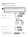
Making Corrections for Printing
Feed Correction
This corrects for errors in the amount of feed of the grit rollers due the type of material.
Be sure to make this setting when you have replaced the material with a different type.
Correcting the amount of feed improves the dot-positioning accuracy in the feed direction, which can help enhance image quality.
- When correcting the amount of feed, set the same conditions for the type of material used and the configuration of
the material (roll material or sheet material) as when actually performing printing.
- When performing test printing for feed correction, load the material correctly (see "2-3 Loading the Material"). If
the material is not loaded correctly, an accurate correction value may not be output.
- When you can set the error for the amount of feed for the grit rollers on the computer, the computer's setting takes
priority.
1
Press the [MENU] key and [ ] key to make the
following screen appear on the display.
2
Press the [
] key to make the following screen appear
on the display.
3
Press the [ENTER] key to start printing a test pattern.
MENU
CALIBRATION
CALIBRATION
TEST PRINT
Gaps
4
Press the [ ] key to make the following screen appear
on the display.
5
Press the [
] key to make the following screen
appear on the display.
6
Use the [ ] and [ ] keys to set the value you checked
in step 4, then press the [ENTER] key.
Perform correction to ensure uniform dot spacing: If
there are gaps in the test pattern, reduce the value. If
there are overlapping areas in the test pattern, increase
the value.
36
Overlapping areas
CALIBRATION
SETTING
SETTING
-0.10%
SETTING
-0.10%
+0.20%
-2.0% to +2.0%
(In steps of 0.05%)
-0.10%
2 Basic Operation
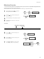
Bidirectional Correction
* Only when the printing direction at the [PRINT QUALITY] menu has been set to [BI-DIRECTION] (bidirectional)
This adjusts slippage when performing bidirectional printing.
Make this adjustment when you have replaced the material with a different type or adjusted the head height.
1
Press the [MENU] key and [ ] key to make the
following screen appear on the display.
2
Press the [
] key to make the following screen
appear on the display.
3
4
Press the [ENTER] key to start printing a test pattern.
MENU
ADJUST BI-DIR
ADJUST BI-DIR
TEST PRINT
Check the test pattern and choose a value with no
displacement.
Test pattern
Value with no displacement
Current setting
+20 +19 +18 +17 +16 +15 +14 +13 +12 +11 +10 +9 +8 +7 +6 +5 +4 +3 +2 +1
5
Press the [ ] key to make the following screen
appear on the display.
6
Press the [
] key to make the following screen
appear on the display.
7
Use the [ ] and [ ] keys to set the value you
checked in step 4, then press the [ENTER] key.
0
-1
-2
-3
-4
-5
-6
-7
-8
-9 -10 -11 -12 -13 -14 -15 -16 -17 -18 -19 -20
ADJUST BI-DIR
SETTING
SETTING
0
SETTING
0
0
+5
-15 to +15 (In steps of 1)
37
2 Basic Operation
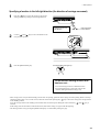
2-6 Ending Printing Operations
Remove the Material
1
If you wish to cut off the piece of the rolled material
containing the printed area, press the [SHEET CUT]
key. Hold down for about 1 second.
The piece is cut off at the present location of the
printing-start line.
* This operation isn't necessary when sending a
material-cutting command from the computer to
separate the material automatically.
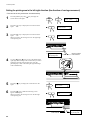
2
When the SETUP LED is lighted, hold down the
[SETUP] key for at least one second.
3
Move the sheet loading lever toward the back of the
unit.
The pinch rollers rise to release the material.
4
Open the front cover.
To remove the material, follow the steps for loading it
in reverse.
The SETUP LED goes out
Sheet loading lever
Separating the Printed Portion
Either of two methods can be used to separate a portion that's already been printed from the roll. One method is to press the [SHEET
CUT] key. The other method is to perform separation automatically by sending a material-cutting command from the computer.
When separating the material by pressing the [SHEET CUT] key
Holding down the [SHEET CUT] key for 1 seconds or longer severs the material at the present position of the printing-start line.
The material is cut off here.
Knife guide
Printing-start line
Printed portion
38
2 Basic Operation
When sending a material-cutting command from the computer to separate
the material automatically
On the computer, set the material-cutting command to "enabled."
The material-separating location during
continuous printing
Start of the next printing operation
70 mm
(2-13/16 in.)
End of printing
Location where separated
70 mm (2-13/16 in.)
Margin (setting on the computer)
39
2 Basic Operation
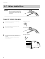
2-7 When Not in Use...
NOTICE
When not in use, move the sheet loading lever
toward the back of the unit to leave the pinch
rollers in the raised state. The pinch rollers
may be deformed if allowed to remain in the
lowered state.
Sheet loading lever
Power Off in Daily Operation
1
If the SETUP LED is lighted, press the [SETUP] key.
Hold down for about 1 second.
2
Move the sheet loading lever toward the back of the
unit and remove the material.
3
Press the [POWER] key to switch off the power.
The carriage moves to the standby position and the head
is capped.
If the carriage is already at the standby position, no
movement takes place.
The SETUP LED goes out
Sheet loading lever
The POWER LED goes out
Standby position
Carriage
40
2 Basic Operation
When Not in Use for a Prolonged Period...
NOTICE
Do not switch off the main power with the printing head in an uncapped state (i.e., while the carriage is on the
platen).
If you leave the carriage uncapped for a long time, doing so may result in clogging of the printing head, making
it unusable.
Before switching off the main power, be sure to press the [POWER] key to switch off the sub power for the FJ600/500/400.
1
After carrying out "Power Off in Daily Operation," turn
off the main power switch.
2
Unplug the power cord from the electrical outlet.
Switch to "O"
* If the unit will be out of use for a month or longer, follow "3-8 When Moving the Unit..." to wash the printing head. Head washing
requires four optionally available cleaning cartridges.
41
3 Maintenance
3 Maintenance
3-1 Replacing the Ink Cartridges
Store ink cartridges out of the reach
of children.
NOTICE
If ink contacts the eyes, flush
immediately with water.
Do not remove any ink cartridges except when shipping the FJ-600/500/400.
Use only the type of filled ink specified for the machine.
If ink runs out, replace immediately with an ink cartridge designed especially for the FJ-600/500/400. Do not
attempt to refill and reuse an empty ink cartridge.
If an ink cartridge is removed, replace it immediately with a new one.
Do not attempt to disassemble an ink cartridge.
Unused ink cartridges should be stored unopened at a temperature of -20°C (-4°F) to 40°C (104°F).
If an ink cartridge is dropped, the shock due to the fall may damage the ink cartridge and make it unusable.
When removing an ink cartridge, do not rush. Detach the cartridge gently. Sudden movement when detaching
may cause ink to be spilled.
- If any ink gets on your hands or clothing, wash it off as soon as possible. Ink stains may become difficult to remove
if allowed to stand.
- Once an ink cartridge has been installed, do not remove it until the ink has been used up. Frequent insertion and
removal may allow air to enter the ink tube and result in a drop in printing quality due to dot drop-out or the like.
42
3 Maintenance
1
Remove the ink cartridge from the ink-cartridge port.
Ink cartridge ports
PIGMENT = pigment ink
2
DYE = dye ink
Insert new ink cartridge.
Use only the type of filled ink specified for the machine.
If ink cartridges other than the filled type are installed, printing with the correct color blending will not be performed.
The present ink type is displayed when the power is turned on.
- INK NOT FILLED: No ink is filled.
Roland FJ-500
Ver.1.00
- PIGMENT 8COLOR: Pigment ink (orange, green, light cyan, light magenta,
black, cyan, magenta, and yellow)
- PIGMENT 4COLOR: Pigment ink (two sets of black, cyan, magenta, and yellow)
- DYE 4COLOR: Dye-based ink (two sets of black, cyan, magenta, and yellow)
Roland FJ-500
PIGMENT 8COLOR
- PIGMENT & DYE 4: Dye-based ink (black, cyan, magenta, and yellow) and
pigment ink (black, cyan, magenta, and yellow)
To change the type of ink, you must use an optionally available cleaning cartridge to replace the ink. For more information, see "3-4 Changing the Type of Ink."
43
3 Maintenance
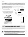
3-2 Checking the Remaining Ink Level
You can use [INK REMAINING] on the display menu to check how much ink is left after the ink cartridges have been installed.
Use this information as a guide for replacing the ink cartridges.
If a partially used ink cartridge is removed and reinstalled, or if a partially used ink cartridge is installed, the cartridge is taken to be
unused, and the displaced amount of remaining ink is not true.
1
Press the [MENU] key and [ ] key to make the
following screen appear on the display.
2
Press the [
] key to make the following screen appear
on the display.
The fewer the markers, the less is the amount of ink left.
The displayed inks indicate the ink cartridges
at the locations shown in the figure.
O
K
G
C
c
M
m
Y
MENU
INK REMAINING
O
K
G
C
c
M
m
Y
O = Orange, G = Green,
c = Light Cyan, m = Light Magenta,
K = Black, C = Cyan,
M = Magenta, Y = Yellow
Remaining ink
In the preceding example, the ink type is
[PIGMENT 8COLOR].
For [PIGMENT 4COLOR], [DYE 4COLOR],
or [PIGMENT & DYE 4], "KCMY" is displayed
instead of "OGcm."
Much
Little
3-3 Cleaning the Printing Heads
Switching on the sub power automatically performs maintenance operations, including cleaning of the printing head. This means that
there is normally no need to perform cleaning otherwise.
If drop-out occurs with printed images, clean the printing head.
* After cleaning, carry out a printing test. Load material.
Perform head cleaning only when there is dot drop-out (gaps) or printing becomes faint.
Performing head cleaning more than necessary subjects the heads to wear and consumes ink. In particular, cleaning
performed at the [POWERFUL] menu for [HEAD CLEANING] can cause premature head wear and consume large
amounts of ink. (Performing cleaning at the [POWERFUL] consumes approximately 45 cc of ink for each group.
This is because all ink in the ink tubes is discharged and replaced with fresh ink.)
44
3 Maintenance
1
Press the [CLEANING] key, then press the [ ] key to
display the screen shown in the figure. Press the
[ENTER] key to start head cleaning.
You can choose to perform cleaning of only the right
head or only the left head by pressing the [ ] key more
times.
Press the [ENTER] key to start head cleaning.
2
When head cleaning ends, press the [ ] key to display
the screen shown in the figure. Press the [ENTER] key
to start the printing test.
3
Refer to "2-4 Test Printing" and check the printingtest results.
If a problem is found, repeat the cleaning.
CLEANING
BOTH HEADS
CLEANING
TEST PRINT
If Drop-out Persists Even After Carrying Out Cleaning
Several Times
1
Press the [MENU] key and [ ] key to make the
following screen appear on the display.
2
Press the [
] key and the [ ] key to display the
screen shown in the figure.
You can choose to perform cleaning of only the right head
or only the left head by pressing the [ ] key more times.
Press the [ENTER] key to start head cleaning
("medium").
3
When head cleaning ends, press the [ ] key to display
the screen shown in the figure. Press the [ENTER] key
to start the printing test.
4
Refer to "2-4 Test Printing" and check the printing-test
results.
If a problem is found, repeat the cleaning.
5
If dot drop-out persists even after carrying out cleaning
] key and the [
("medium") several times, press the [
] key to display the screen shown in the figure.
You can choose to perform cleaning of only the right
head or only the left head by pressing the [ ] key more
times.
Press the [ENTER] key to start head cleaning
("powerful").
6
When head cleaning finishes, perform a printing test to
check the results.
MENU
HEAD CLEANING
HEAD CLEANING
BOTH MEDIUM
HEAD CLEANING
TEST PRINT
HEAD CLEANING
BOTH POWERFUL
45
3 Maintenance
If Performing Cleaning Several Times at the [POWERFUL]
Menu Does Not Correct the Drop-out Problem
If performing cleaning several times at the [POWERFUL] menu does not correct the image drop-out problem, use the included cleaning
kit. For information on how to use the cleaning kit, refer to the following section, "Using the Cleaning Kit to Clean the Printing Heads."
Using the Cleaning Kit to Clean the Printing Heads
If image drop-out persists even after performing cleaning with the cleaning kit, or if the cleaning kit is used up, contact your authorized
Roland DG Corp. dealer or Roland DG Corp. service center.
The heads are consumable parts. The useful life is six billion shots per nozzle.
Cleaning using the cleaning kit should be carried out when automatic cleaning and forced cleaning from the
[HEAD CLEANING] menu fail to correct image drop-out. Remove any ink buildup of dust or grime around the
printing heads, which can cause image drop-out or ink drips. We also recommend performing periodic cleaning
using the cleaning kit to prevent problems like these during printing.
Before starting cleaning, read through this section carefully to familiarize yourself with the procedures, then
carry out the cleaning operations quickly and accurately.
Cleaning is performed while the caps on the printing heads are detached, so cleaning must be completed before
the heads dry out. It is suggested that cleaning be completed in ten minutes or less.
If it appears that cleaning operations may take more than ten minutes, stop the cleaning operations and follow
the steps below.
1.
2.
3.
4.
Return the carriage to standby position and cap the heads.
Attach the cover and tighten the screws.
Switch on the power, and from the [HEAD CLEANING] menu, carry out cleaning of the heads.
When the head cleaning ends, perform cleaning using the cleaning kit again.
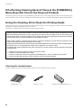
Checking the Included Items
The following items are packed with the cleaning kit. Before use, check to make sure they are present.
Cleaning sticks -- 10
46
Tweezers -- 1 pair
Sponges (for cleaning the hooks) -- 10
3 Maintenance
Overview of the Cleaning Method
1) Switch off the power.
2) Detach the cover.
3) Move the carriage away from standby position.
4) Clean the heads (on the left and right sides) and the hooks inside the carriage, and clean between
the hooks and the heads.
Carriage
Hook
Wipe away soiling on all four sides (the metal areas).
Left-hand head
Right-hand head
Ink nozzles (at bottom area of each head)
* Do not touch these areas.
Bottom surface of the carriage
as seen from the front
5) Clean the rubber caps, wipers, and valves.
Carriage
Sponges
Rubber caps
(black)
Top view
Wipers
Valves
6) Replace the sponge (for cleaning the hook).
* Do this only if the sponge has soaked up ink.
7) Return the carriage to standby position.
8) Attach the cover.
9) Switch on the power.
10) Check the results of cleaning.
47
3 Maintenance
Performing Cleaning
NOTICE
When attaching or detaching the cover, hold it only at the specified location.
Also, before starting cleaning, be sure to detach the cover.
It may be damaged if dropped.
When performing cleaning, do not touch any area other than the specified locations.
Doing so may damage the equipment.
To discharge static electricity from your body, carry out cleaning as described in the procedure. Failure to
follow the procedure for discharging static electricity may result in breakdown.
1
After pressing the [POWER] key to switch off the sub
power, turn off the main power switch.
The POWER LED goes out
Switch to "O"
2
Open the front cover.
3
Detach the cover shown in the figure.
Remove the two screws.
Screws
4
1) As shown in the figure, place the hand on the bottom
portion of the cover and flip the top portion back
toward you.
1)
2) Slide the cover to the right to detach it.
Cover
2)
5
48
To discharge static electricity from your body, touch the
location shown in the figure.
3 Maintenance
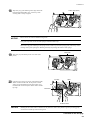
6
Pull out the carriage in the direction shown in the figure.
You may need to apply slight force to move it.
Carriage
7
Insert a cleaning stick into the space shown in the figure.
Cleaning stick
8
Move the carriage to a location where the cleaning stick reaches the left-hand side surface of the left-hand head, and wipe away
any grime on the left-hand side surface (the metal area) of the left-hand head.
Left-hand side
Wipe away any grime on the metal area.
Left-hand head
* Do not touch the ink nozzle
(at the bottom area of the head).
Continued on the next page
49
3 Maintenance
NOTICE
Do not touch the ink nozzle (at the bottom area of the head).
Wipe only the silver-colored metal area.
There is no need to apply force when wiping. You can remove dust by simply stroking the surface.
Do not use a soiled cleaning stick.
Use lint-free tissue or the like to remove grime adhering to a cleaning stick. Also, if a cleaning stick becomes
extremely dirty, discard it and perform cleaning with a new one.
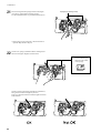
9
Move the carriage to a location where the cleaning stick reaches the right-hand side surface of the left-hand head, and wipe away
any grime on the right-hand side surface (the metal area) of the left-hand head.
Left-hand head
Right-hand side surface
Wipe away any grime on the metal area.
* Do not touch the ink nozzle
(at the bottom area of the head).
10
Move the carriage to a location where the cleaning stick reaches the front surface of the left-hand head.
While holding the tip of the cleaning stick against the front of the head, move the carriage to the left and right to wipe away
grime.
Left-hand head
Front surface
Wipe away any grime on the metal area.
* Do not touch the ink
nozzle (at the bottom
area of the head).
50
3 Maintenance
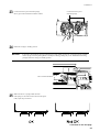
11
Bend a cleaning stick as shown in the figure.
Cleaning stick
12
Insert the cleaning stick into the space shown in the figure
as far as it will go.
13
Move the carriage to a location where the cleaning stick
reaches the back surface of the left-hand head.
While holding the tip of the cleaning stick against the
back of the head, move the carriage to the left and right
to wipe away grime.
Left-hand head
Back surface
Wipe away any grime on the metal area.
* Do not touch the ink nozzle (at
the bottom area of the head).
Continued on the next page
51
3 Maintenance
14
Repeat steps 7 through 13 to clean the right-hand head in
the same way.
Wipe away soiling on all four sides (the metal areas).
Right-hand head
15
Clean the hooks on the right side of the left and right
heads (two places).
Hooks
Between the heads and the hooks
16
Wipe away any grime between the heads and the hooks
(two places). These areas are susceptible to buildup of
grime. Wipe them off carefully.
17
Pull the carriage by hand to move it to the left-hand side
until the black rubber caps, sponges, and tubes can be
seen.
Top view
Rubber caps
(black)
Sponges
Carriage
52
3 Maintenance
18
Wipe away any grime adhering to the edges of the lefthand and right-hand rubber caps. Use the tip of the
cleaning stick to scrape off grime.
NOTICE
Rubber caps (black)
Be sure to use one of the included cleaning sticks.
If no grime is present, do not touch the sponges inside the rubber caps.
When removing grime adhering to the sponge inside a rubber cap, touch the sponge gently with the tip of the
cleaning stick to pick up the grime. Rubbing forcefully may damage the surface of the sponge.
Valve sides
19
Wipe away any ink buildup on the valve sides (four
places).
20
Clean the wiper areas (two places on the left and right).
When viewed from the front, the wiper has a rubber
surface on its right-hand side and a felt surface on its
left-hand side. Clean mainly the rubber surface and the
top edge.
Top edge
Wiper
Wiper
Felt surface
Rubber surface
NOTICE
Rubbing the felt surface with too much force may make the surface fuzzy. Remove grime by stroking gently
several times with the tip of the cleaning stick.
Continued on the next page
53
3 Maintenance
21
If ink is oozing from the sponges shown in the figure
(two places), replace them with new sponges.
Use the included tweezers to pull them out from above.
Sponges (for cleaning hooks)
* If the sponge is not oozing ink, it doesn't need to be
replaced. Skip ahead to step 24.
22
Orient a new sponge (included with the cleaning kit) as
shown in the figure (lengthwise) and insert it.
Pass the tab through
the hole in the center
of the sponge.
Orient as shown in the figure (lengthwise) and attach it,
being careful to hold it straight as you do so.
There is no distinction between left and right or between
front and back.
54
3 Maintenance
23
Use the tweezers to press down the sponge.
Slowly press it downward until it makes contact.
24
Return the carriage to standby position.
NOTICE
Use the tweezers to press
down the sponge.
If allowed to stand with the carriage remaining away from standby position for a prolonged period, problems
such as drying-out of the printing heads or dot drop-out during printing may occur. When finished cleaning,
promptly return the carriage to standby position.
Move inward until flush.
25
Make sure there is a sponge under the hook.
If the sponge is not at the location shown in the figure
(OK), repeat steps 22 and 23.
Continued on the next page
55
3 Maintenance
26
Attach the cover.
27
Close the front cover.
28
Turn on the main power switch at the side of the unit,
then press the [POWER] key to switch on the sub power.
29
Screws (at two places)
The POWER LED lights up
Load the material.
30
Press the [CLEANING] key, then press the [ ] key
to display the screen shown in the figure. Press the
[ENTER] key, head cleaning starts.
31
When head cleaning ends, press the [ ] key to display
the screen shown in the figure. Press the [ENTER] key
to start the printing test.
32
Examine the printing test results to make sure all dots are
printed attractively.
56
Switch to "I"
CLEANING
BOTH HEADS
CLEANING
TEST PRINT
3 Maintenance
3-4 Changing the Type of Ink
You can perform cleaning four times
per cleaning cartridge (for the FJ-600,
three times per cleaning cartridge).
* Due to the structure of the head,
about twice as much cleaning fluid
is consumed as for other areas.
When changing the type of ink in use, follow the steps below to
replace the ink.
Ink replacement requires four optionally available cleaning
cartridges.
The amount of cleaning fluid used varies according to the area
cleaned.
You can perform cleaning seven times
per cleaning cartridge(for the FJ-600,
six times per cleaning cartridge).
1
Press the [MENU] key and [ ] key to make the
following screen appear on the display.
2
Press the [
] key to make the following screen
appear on the display.
3
Use the [ ] key to select [CHANGE INK SET], then
press the [
] key.
4
Use the [ ] and [ ] keys to select the new type of ink
to use, then press the [ENTER] key.
* When you are changing from [PIG. 8] (eight-color
pigment ink) to something else, turn over the
plates for the ink-cartridge ports. For more
information, refer to "2-1 Installing Ink Cartridges"
-- "Before You Install the Ink Cartridges" and "Turn
Over the Plate."
MENU
INK CONTROL
INK CONTROL
EMPTY MODE
INK CONTROL
CHANGE INK SET
CHANGE INK SET
PIG. 8 DYE 4
- PIG. 8: Pigmented ink (orange, green, light cyan, light
magenta, black, cyan, magenta, and yellow)
- PIG. 4: Pigmenedt ink (black, cyan, magenta, and yellow two sets)
- DYE 4: Dye-based ink (black, cyan, magenta, and yellow two sets)
- PIG&DYE: Dye-based ink (black, cyan, magenta, and yellow)
and pigmented ink (black, cyan, magenta, and yellow)
Continued on the next page
57
3 Maintenance
5
When the display shown in the figure appears, discard
the discharged ink in the drain bottle.
* Be sure to discard the discharged ink.
Attempting to replace the ink while discharged
ink remains may cause discharged ink to
overflow from the bottle.
EMPTY
6
Attach the drain bottle and press the [ENTER] key.
The colors for the ink cartridges to pull out flash
according to the type of ink you are changing.
REMOVE CARTRIDGE
[OGcmKCMY]
DRAIN TANK
The ink cartridge to pull out is at the location shown in the figure.
REMOVE CARTRIDGE
[OGcmKCMY]
In the preceding example, the ink type is [PIGMENT 8COLOR].
For [PIGMENT 4COLOR], [DYE 4COLOR], or [PIGMENT &
DYE 4], "KCMY" is displayed instead of "OGcm."
7
After you have pulled out all the ink cartridges whose
colors are flashing, ink replacement starts. Follow the
messages on the display to carry out the procedure.
If you are replacing all eight ink colors, then when you
finish replacing the first four colors, the display returns
to the screen shown in step 6.
Follow the messages on the display to replace the
remaining four colors.
Messages appearing during ink replacement
SET CLEANING
LIQUID[OGcmKCMY]
Insert a cleaning cartridge into the ink cartridge port
for the flashing color.
REMOVE CLEANING
LIQUID[OGcmKCMY]
Remove the cleaning cartridge from the ink cartridge
port for the flashing color.
O = Orange, G = Green, c = Light Cyan, m = Light Magenta,
K = Black, C = Cyan, M = Magenta, Y = Yellow
8
When the display shown in the figure appears, discard
the discharged ink in the drain bottle.
* Be sure to discard the discharged ink.
Attempting to replace the ink while discharged
ink remains may cause discharged ink to
overflow from the bottle.
9
When the display shown in the figure appears, insert
the ink cartridge to be newly used.
The colors for the ink cartridges to insert flash
according to the type of ink you are changing.
* When set to [PIG&DYE] (four-color pigment ink
and four-color dye-based ink), then while facing
the back of the machine, insert the dye-based
ink cartridges in the four places on the left and
the pigment ink cartridges in the four places on
the right.
10
When the display shown in the figure appears, ink
replacement is finished.
Press the [SETUP] key to go back to the top menu.
58
EMPTY
DRAIN TANK
SET CARTRIDGE
[OGcmKCMY]
CHANGE INK SET
PIG. 8 PIG. 8
3 Maintenance
3-5 Disposing of Discharged Ink
Dispose of ink in the drain bottle as described below.
If any ink gets on your hands or clothing, wash it off as soon as possible. Ink stains may become difficult to remove
if allowed to stand.
1
Press the [POWER] key to switch off the sub power.
2
Remove the drain bottle and attach the bottom plug.
The POWER LED goes out
Drain bottle
3
Bottom plug
Put a water-absorbent, combustible material such as a
paper or cloth into the plastic bag, and soak up the ink.
Combustible
material such as a
paper or cloth
4
Dispose of it as combustible material impregnated with
discharged ink.
59
3 Maintenance
3-6 How to Replace the Separating Knife
Do not touch the tip of the
separating knife with your fingers.
Make sure the power to the unit is
off before attempting to replace the
separating knife.
Doing so may result in injury.
Doing so may result in injury.
NOTICE
When replacing the knife, do not pull out the carriage.
If the machine is allowed to stand for a prolonged period with the carriage pulled out, head clogging or even
damage to the printing heads may occur.
If the separating knife becomes dull, replace with the included replacement blade.
1
Press the [POWER] key to switch off the power.
2
Turn off the main power switch.
3
Remove the separating knife.
The POWER LED goes out
Switch to "O"
(2) Grasp the screw portion, and slowly pull it out in the
direction of the arrow.
* Do not pull back
while doing this.
(1) Loosen the screw until it slips out.
* If a blade remains in the carriage, use the tweezers in
the cleaning kit to remove it.
60
3 Maintenance
4
Replace with a new knife.
Positioning groove
The knife is secured in
place by the magnet.
5
Install the separating knife.
(1) Grasp the screw portion and slowly insert it into the groove.
(2) Tighten the screw.
* Take care to ensure that the knife does not slip.
61
3 Maintenance
3-7 Cleaning
NOTICE
When performing cleaning, turn off the main power switch.
* Before turning off the main power, press the [POWER] key to switch off the sub power.
Never lubricate the mechanisms.
Do not clean with solvents (such as benzine or thinners).
Periodically clean the platen. Attractive printing may become impossible if the platen is soiled.
Do not touch the printing heads or allow the printing heads to come in contact with anything except ink.
Cleaning the body
Use a cloth moistened with water then wrung well, and wipe gently to clean. Wipe the operation panel and display gently with a clean,
soft cloth.
Cleaning the platen
Use a cloth moistened with water then wrung well, and wipe gently to clean.
For buildup of cutting dust on the platen, use a commercially available brush to brush them away toward the front.
Cleaning the grit rollers
Use a commercially available brush to remove dust and other detritus.
Any adhering grime may prevent the material from being held in place securely.
Cleaning the pinch rollers
Use a cloth moistened with water then wrung well, and wipe gently to clean.
Cleaning the reflective tape
If the tape becomes dirty, use a cloth moistened with water then wrung well, and wipe gently to clean.
Cleaning the front cover
Use a cloth moistened with water then wrung well, and wipe gently to clean.
62
3 Maintenance
3-8 When Moving the Unit...
NOTICE
When moving the unit, first carry out head washing, then secure the carriage in place. Head washing requires
four optionally available cleaning cartridges.
Do not attempt to move with the FJ-600/500/400 unit upside down. Doing so may cause discharged fluid remaining
in the machine to spill or leak, resulting in breakdown or faulty operation.
1
If there is material loaded, hold down the [SETUP] key
for 1 second or longer to cancel setup, then remove the
material (see "2-6 Ending Printing Operations - Remove
the Material").
2
Press the [MENU] key and [ ] key to make the
following screen appear on the display.
3
Press the [
] key to make the following screen
appear on the display.
4
Use the [ ] key to select [HEAD WASH], then press
the [ENTER] key.
5
When the display shown in the figure appears, discard
the discharged ink in the drain bottle.
* Be sure to discard the discharged ink.
Attempting to clean the heads while discharged ink
remains may cause discharged ink to overflow from
the bottle.
EMPTY
6
Mount the drain bottle and press the [ENTER] key to
display the screen shown in the figure.
REMOVE CARTRIDGE
[OGcmKCMY]
MENU
INK CONTROL
INK CONTROL
EMPTY MODE
INK CONTROL
HEAD WASH
DRAIN TANK
Continued on the next page
63
3 Maintenance
7
After you have pulled out all the ink cartridges whose
colors are flashing, head cleaning starts. Follow the
messages on the display to carry out the procedure.
When cleaning for the first four colors finishes, the
display returns to the screen shown in step 6. Follow
the messages on the display to perform cleaning for
the remaining four colors.
Messages appearing during head washing
SET CLEANING
LIQUID[OGcmKCMY]
Insert a cleaning cartridge into the ink cartridge port
for the flashing color.
REMOVE CLEANING
LIQUID[OGcmKCMY]
Remove the cleaning cartridge from the ink cartridge
port for the flashing color.
O = Orange, G = Green, c = Light Cyan, m = Light Magenta,
K = Black, C = Cyan, M = Magenta, Y = Yellow
8
When head cleaning finishes, the sub power shuts of
automatically.
Switch off the main power switch.
9
Detach the power cord and the cable connecting the unit
to the computer.
10
Remove the drain bottle and attach the bottom plug
instead.
Switch to "O"
Drain bottle
11
64
Referring to "Unpacking and Repacking" on the packing
carton, secure the carriage in place and pack the unit in
the carton.
Bottom Plug
4 User's Reference
4 User's Reference
4-1 Materials
* Use genuine media for the FJ-600/500/400.
Conditions for Usable Materials
A) Maximum material thickness
: 1.0 mm (0.039 in.) (When head is raised)
B) Maximum diameter for roll material : 180 mm (7-1/16 in.) (Surface to be
printed must face outward)
C) Core inner diameter for roll material: 50.8 mm or 76.2 mm (2 in. or 3 in.)
D) Maximum weight for roll material : 20 kg (44.1 lb.)
E) Roll material that is not taped down to the paper tube
Side view of roll material
Acceptable Material Widths
FJ-600
FJ-500
FJ-400
210 to 1625 mm (8-5/16 to 64 in.)
210 to 1371 mm (8-5/16 to 54 in.)
210 to 1117 mm (8-5/16 to 44 in.)
4-2 Adjusting the Height of the Printing Head
When using material that is thick or susceptible to warping, material feed may not proceed smoothly, or the material may jam. When
such material is loaded, you can adjust the height of the printing head.
This should normally be left at position 1 (low). If printing results in material feed that is not smooth because of problems such as the
material jamming or the head catching on the material, position at 2 (high).
When the height of the printing head has been adjusted, it is necessary to perform bidirectional correction (only when the printing
direction for [PRINT QUALITY] has been set to [BI-DIRECTION]). For more information about bidirectional correction, see "2-5
Printing - Making Corrections for Printing - Bidirectional Correction."
Lever
Height of the printing head
2
2
High
1
1
Low
Continued on the next page
65
4 User's Reference
1
Open the front cover.
2
Press the [MENU] key and the [
screen shown in the figure.
3
Press the [
] key to display the screen shown in the
figure.
When the screen shown in the figure appears, the
carriage simultaneously moves to the left.
] key to display the
MENU
HEAD HEIGHT
HEAD HEIGHT
HIGH
LOW
Present setting displayed
4
Move the lever to adjust the height of the head.
When you move the lever, the machine beeps and the
screen display changes.
- When the lever is moved to position 1 (low):
One beep
- When the lever is moved to position 2 (high):
Two beeps
* Move the lever until it stops. If it is not at position 1 or
position 2, bidirectional printing may be misaligned.
5
Press the [
position.
6
Close the front cover.
66
] key to return the carriage to standby
4 User's Reference
4-3 Printing Area
The material's printable width (the direction of carriage movement) is determined by the width of the loaded material. When the
[SETUP] key is pressed after loading the material, the width of the material is detected and the printing area appears on the display. The
printing area is normally 10 mm (3/8 in.) inward from the respective left- and right-hand edges of the material.
When the printable width have been specified with the [PRINT AREA] menu, the margins are in accordance with these setting values.
Maximum printing width
[FJ-600]
1615 mm (63-9/16 in.)
[FJ-500]
1361 mm (53-9/16 in.)
[FJ-400]
1107 mm (43-9/16 in.)
107 mm (4-1/4 in.)
Material
Printing area
Length of one roll
Origin (0, 0)
70 mm (2-13/16 in.)
10 mm (3/8 in.)
10 mm (3/8 in.)
When the printable width have been specified with the [PRINT AREA] menu,
the margins are in accordance with these setting values.
67
4 User's Reference
4-4 Display Menus Flowchart
For details about each of the menus, see the "4-5 Description of Keys and Display Menus."
Selecting the language for
screen messages
MENU LANGUAGE
ENGLISH
Roland FJ-500
Ver.1.00
When the power is turned
on for the first time, or turned
on after removing the ink
Roland FJ-500
PIGMENT 8COLOR
Use
or
to select.
Press the [ENTER] key
to enable the setting.
MENU LANGUAGE
JAPANESE
Roland FJ-500
INK NOT FILLED
RAISE THE HEAD
No ink is filled.
Setting the initial
head-height position
Move the location to the
"2 (High)" position.
LOWER THE HEAD
Move the lever to the
"1 (Low)" position.
LOWER THE HEAD
Press the [ENTER] key.
SELECT INK TYPE
PIGMENT 8COLOR
Select the installed ink type
and press the [ENTER] key.
SETUP SHEET
PIGMENT 8COLOR/PIGMENT 4COLOR/
DYE 4COLOR/PIGMENT&DYE 4
Load the material and press
the [SETUP] key
Printable width of
the loaded material
INSTALL
DRAIN TANK
Attach the drain bottle,
and press [ENTER] key.
FILLING INK...
The system will execute
ink fill.
Top
W 1234 mm
menu NORMAL
BI-DIR
The settings for [PRINT QUALITY]
(Printing Direction) display only in the case
of [BI-DIRECTION].
Settings for [PRINT QUALITY] (Printing Quality)
vPHOTO/vSUPER/vNORMAL/SUPER/NORMAL/DRAFT
68
4 User's Reference
PRINT QUALITY
NORMAL
PRINT QUALITY
BI-DIRECTION
vPHOTO/vSUPER/vNORMAL/
SUPER/NORMAL/DRAFT
UNI-DIRECTION/
BI-DIRECTION
Use
or
to select.
Press the [ENTER] key to enable the setting.
CLEANING
TEST PRINT
Press the [ENTER] key
to print a test pattern.
* Not displayed during printing.
CLEANING
BOTH HEADS
Press the [ENTER] key
to perform head cleaning.
CLEANING
LEFT HEAD
Press the [ENTER] key
to perform head cleaning.
CLEANING
RIGHT HEAD
Press the [ENTER] key
to perform head cleaning.
69
4 User's Reference
MENU
SHEET TYPE
SHEET TYPE
OPAQUE OPAQUE
OPAQUE/CLEAR
Displayed only when the material has been set up.
MENU
PRINT AREA
PRINT AREA
RIGHT EDGE
RIGHT EDGE
SET
RIGHT EDGE
CANCEL
PRINT AREA
LEFT EDGE
LEFT EDGE
SET
LEFT EDGE
CANCEL
MENU
HEAD HEIGHT
HEAD HEIGHT
HIGH
LOW
MENU
HEAD CLEANING
HEAD CLEANING
TEST PRINT
HEAD CLEANING
TEST PRINT
HEAD CLEANING
BOTH MEDIUM
HEAD CLEANING
BOTH POWERFUL
HEAD CLEANING
LEFT MEDIUM
HEAD CLEANING
LEFT POWERFUL
HEAD CLEANING
RIGHT MEDIUM
HEAD CLEANING
RIGHT POWERFUL
To the [INK CONTROL] menu
70
4 User's Reference
[HEAD CLEANING] menu
MENU
INK CONTROL
INK CONTROL
EMPTY MODE
EMPTY MODE
LATER
PROMPT
LATER/PROMPT
INK CONTROL
FILL INK
INK CONTROL
PUMP UP
INK CONTROL
HEAD WASH
INK CONTROL
CHANGE INK SET
CHANGE INK SET
PIG. 8 DYE 4
PIG. 8/PIG. 4/DYE 4/PIG&DYE
MENU
ADJUST BI-DIR
ADJUST BI-DIR
TEST PRINT
ADJUST BI-DIR
SETTING
SETTING
0
0
-20 to +20 (In steps of 1)
MENU
CALIBRATION
CALIBRATION
TEST PRINT
CALIBRATION
SETTING
SETTING
-0.10
-0.10
-2.0 to +2.0 (In steps of 0.05)
MENU
SLEEP
SLEEP
15min
15 min
NONE, 15 to 120 min.
(In steps of 15 min)
MENU
UNIT
UNIT
mm
mm
mm/INCH
MENU
6COLOR MODE
• Move to the previous menu
screen or the next menu
screen
• Select the value for a setting
• Moves the material (when
specifying the printing location)
6COLOR MODE
OR-GR
Lc-Lm
OR-GR/Lc-Lm
Displayed only in the case of PIGMENT 4COLOR or DYE 4COLOR.
MENU
HEAD SELECT
HEAD SELECT
TOGGLE TOGGLE
• Move to a submenu screen
• Moves the carriage (when
specifying the printing location)
TOGGLE/LEFT/RIGHT
MENU
SYSTEM REPORT
PERFORMING
TEST PRINT
MENU
FACTORY DEFAULT
NOW PROCESSING..
MENU
INK REMAINING
O
K
G
C
c
M
m
Y
• Move to the previous menu
screen
• Moves the carriage (when
specifying the printing location)
• Executes the menu
• Locks in the value for a setting
To the [SHEET TYPE] menu
71
4 User's Reference
4-5 Description of Keys and Display Menus
Description of Keys
Key
Top
menu
Submenu
Setting
range
Default
value
—
—
This switches on and off the sub power . When the
power is switched on, the POWER LED lights up.
—
—
—
—
This detects the presence and the width of the material,
and displays the printable width.
The SETUP LED flashes while detection of material
width is in progress. When setup finishes, the SETUP
LED lights up continuously.
Also press this key when removing the material.
Pressing this key when any of the various menu screens
is displayed returns you to the top screen. (When this is
done, material setup cannot be canceled.)
—
—
—
—
The [PAUSE] key pauses printing. The PAUSE LED
lights up while paused.
Pressing this key again cancels the paused state.
Holding down the [SETUP] key for about 1 second
while paused causes remaining data to be cleared and
cancels the material's setup state.
—
—
—
—
This sets the print-start location in the horizontal
direction (the direction of carriage movement). For
more information, see "2-5 Printing -- Printing at the
Desired Location -- Specifying a location in the leftright direction (the direction of carriage movement)."
—
—
—
This displays the [PRINT QUALITY] menu for setting
image quality.
This is used to specify the printing quality and unidirectional or bidirectional printing.
Settings cannot be made while printing is in progress.
To exit the [PRINT QUALITY] menu screen, press the
[MENU] key, the [CLEANING] key, or the [SETUP]
key.
When you can make the settings for the printing mode
and printing direction on the computer, the computer's
settings take priority.
For more information, see "2-5 Printing -- Setting the
Printing Mode."
PRINT
QUALITY
72
Function
[Printing
[Printing
quality]
quality]
vPHOTO
NORMAL
vSUPER
vNORMAL
SUPER
NORMAL
DRAFT
[Printing
[Printing
direction]
direction]
UNI-DIRECTION BIBI-DIRECTION
DIRECTION
4 User's Reference
Key
Top
menu
Submenu
CLEANING
TESTPRINT
BOTH HEADS
LEFT HEAD
RIGHT HEAD
Setting
range
Default
value
This displays the [CLEANING] menu for cleaning of
the printing head. Before starting to print, you can
carry out a printing test to check the printing quality.
You can perform cleaning while in any state. Note that
[TEST PRINT] is not displayed while the printing is in
progress.
[TEST PRINT]: Performs a printing test. If there is a
problem, then continue by carrying out cleaning.
[BOTH HEADS]/[LEFT HEAD]/[RIGHT HEAD]:
Begins cleaning of the printing heads. After cleaning,
carry out a printing test to make sure there are no
problems.
For more information, see "2-4 Test Printing" and "3-3
Cleaning the Printing Heads."
—
—
Function
—
—
This severs the material at the present position of the
print-start line. Press this to separate the portion that
has been printed from the roll.
You cannot sever a piece of material while printing is in
progress.
For more information, see "2-6 Ending Printing
Operations -- Separating the Printed Portion."
—
—
—
—
These move the material and the carriage.
When a menu is displayed, these move among the
menu items.
—
—
—
—
This enters the menu mode.
When a menu is displayed, the [ ] and [
move to the next menu,
the [
] moves to a submenu, and the [
moves to the previous screen.
—
—
—
—
] keys
] key
—
—
This is used to accept, execute, or save the item shown
on the display.
LANGUAGE
—
This sets the language for screen messages. You can
select either English or Japanese.
ENGLISH/
JAPANESE
ENGLISH
+
73
4 User's Reference
Description of Menus
Pressing the [MENU] key enters the menu mode.
Top
menu
Submenu
Function
SHEET
TYPE
—
This is used to select either transparent or opaque material.
Select [OPAQUE] when the material loaded on the unit is not transparent. When the material loaded on the unit is not transparent, select
[OPAQUE]. When you are using transparent material or the printing
area cannot be detected, select [CLEAR]. For more information, see
"4-7 What to Do If... -- [SHEET SET ERROR SET AGAIN] appears
andthe material cannot be detected even when the [SETUP] key is
pressed."
PRINT
AREA
RIGHT EDGE
LEFT EDGE
HEAD
HEIGHT
HEAD
CLEANING
74
* This appears only when the material is in a loaded state.
Setting
range
OPAQUE/
CLEAR
Default
value
OPAQUE
—
—
This sets the printing area in the left-right direction (the direction of
carriage movement) of the loaded material.
With transparent material, automatic detection of the material width is
not performed. In such cases, use the [PRINT AREA] menu to specify
the printing area in the left-right direction. Even when using opaque
material, this can be specified when printing in a specific area.
For more information, see "2-5 Printing -- Printing at the Desired
Location Specifying a location in the left-right direction (the direction
of carriage movement)."
This sets the height of the printing heads.
To make the setting, display this menu, then move the lever on the side
of the unit's carriage.
For more information, see "4-2 Adjusting the Height of the Printing
Head."
Before starting to print, you can carry out a printing test to check the
printing quality.
If the printing test shows a problem, clean the printing head.
Because cleaning subjects the head to wear and consumes ink, it should
only be performed when absolutely necessary. Performing cleaning
from the Powerful menu in particular subjects the head to early wear
and used up large amounts of ink.
TEST PRINT [TEST PRINT]: Performs a printing test. If a problem is found, then
continue by carrying out cleaning.
BOTH MEDIUM [BOTH MEDIUM]/[RIGHT MEDIUM]/[LEFT MEDIUM]: Performs
LEFT MEDIUM cleaning of the printing heads. After cleaning, carry out a printing test
RIGHT MEDIUM to make sure there are no problems with printing quality.
Normally, head cleaning should be performed by pressing the
[CLEANING] key.
BOTH POWERFUL [BOTH POWERFUL]/[RIGHT POWERFUL]/[LEFT POWERFUL]:
LEFT POWERFUL Used when performing cleaning with Medium several times does not
RIGHT POWERFUL restore the printing quality. After cleaning, carry out a printing test to
make sure there are no problems with printing quality.
For more information, see "2-4 Test Printing" and "3-3 Cleaning the
Printing Heads."
HIGH/LOW
—
LOW
—
4 User's Reference
Top
menu
INK
CONTROL
ADJUST
BI-DIR
CARIBRATION
SLEEP
Submenu
Function
[EMPTY MODE]: When replacement of the ink cartridge becomes
necessary while printing is in progress, this setting determines whether
printing continues or pauses.
This setting is used when the ink cartridge cannot be changed immediately during printing, such as during unattended operation at night.
[LATER] causes printing to continue without pause even if ink refilling
becomes necessary. Printing continues with the small amount of ink
remaining, so the printed image may become faint as the ink runs out.
In general, it should possible to perform about 1 m2 (10 ft2) of printing
once this message appears, although the actual varies widely according
to the amount of ink needed for the particular image. Printing is
continued only for the data currently being printed. Operation stops
after one image is output.
[PROMPT] causes operation to pause immediately when the ink
cartridge needs to be changed. Printing is resumed by replacing the
cartridge. Please note, however, that the colors of an image in progress
may no longer be perfectly matched if the unit is allowed to remain
paused for two or three hours before resuming printing.
FILL INK
[FILL INK]: This fills the printing heads with ink. Normally there is no
need to make this setting, because filling is automatic.
PUMP UP
[PUMP UP] : Drains ink from the printing heads.
HEAD WASH [HEAD WASH] : This washes the printing heads with optionally
available cleaning cartridges. For more information, see "3-8 When
Moving the Unit... ."
CHANGE
[CHANGE INK SET] : Performs the [HEAD WASH] and [FILL INK]
INK SET
operations.
This is used when switching the ink type. Before running this, choose
the type of ink to be used after the change.
For more information, see "3-4 Changing the Type of Ink."
EMPTY
MODE
Setting
range
Default
value
[EMPTY
MODE]
LATER/
PROMPT
[EMPTY
MODE]
PROMPT
[CHANGE
INK SET]
PIG. 8/
PIG. 4/
DYE 4/
PIG&DIE
This adjusts for slippage when performing bidirectional printing.
This must be readjusted when you have replaced the material with a
different type or adjusted the head height.
TEST PRINT [TEST PRINT]: This menu is for verifying the adjustment.
SETTING
[SETTING]: This sets the correction value.
For more information, see "2-5 Printing -- Making Corrections for
Printing -- Bidirectional Correction."
[SETTING]
-20 to +20
(In steps of 1)
This corrects for errors in the amount of feed of the grit rollers due the
type of material.
Be sure to make this setting when you have replaced the material with
a different type.
Make this setting again when horizontal stripes are plainly visible on
printing results.
TEST PRINT [TEST PRINT]: This menu is for verifying the adjustment.
SETTING
[SETTING]: This sets the correction value.
When you can set the error for the amount of feed for the grit rollers on
the computer, the computer's setting takes priority.
For more information, see "2-5 Printing -- Making Corrections for
Printing -- Feed Correction."
-2.0% to
+2.0%
(In steps of
0.05%)
—
This sets the time that elapses before the unit enters the SLEEP mode.
The SLEEP mode is enabled when the FJ-600/500/400 has been
inactive for a specified time. (When in the SLEEP mode, the POWER
LED flashes once per second.)
To release the SLEEP mode...
- Touch any key on the control panel.
- Send data from the computer (only when the SETUP LED is lit).
- Open the front cover.
- Move the sheet loading lever toward the back of the unit.
NONE/15
min to
120 min
(In steps of
15 min)
0
0%
15 min
75
4 User's Reference
Top
menu
Setting
range
Default
value
Submenu
Function
UNIT
—
This selects millimeters or inches as the unit of measurement for the
width displayed on the top menu after setting up the material. When
inch display is used, values are displayed to the first digit to the right of
the decimal point.
mm/INCH
mm
6COLOR
MODE
—
Make this setting when you are using data for six-color printing.
It has no effect on processing data for four-color or eight-color
printing.
The menu is for performing printing using six-color printing data for
older Hi-Fi JET models from Roland DG Corp.
When processing six-color printing data as KCMY + OrGr (black,
cyan, magenta, and yellow plus orange and green, choose [OR-GR].
When processing the six-color printing data as KCMY + LcLm (black,
cyan, magenta, and yellow plus light cyan and light magenta), choose
[Lc-Lm].
* Performing printing using six-color data for an older model requires
taking into account the differences in resolution and the amount of
ink received, and adjusting the output profile appropriately. Note that
the output results will not be exactly equivalent to those obtained
with the older model.
Also, if the FJ-600/500/400 is set to a printing mode that is not
compatible with the older model, correct output results may not be
obtained even when six-color printing data is sent.
The only printing mode on the FJ-600/500/400 that is compatible
with older models is NORMAL.
[OR-GR]: In the six-color data, the two colors other than KCMY
(black, cyan, magenta, and yellow) are processed as OrGr (orange and
green).
[Lc-Lm]: In the six-color data, the two colors other than KCMY (black,
cyan, magenta, and yellow) are processed as LcLm (light cyan and
light magenta).
OR-GR/
Lc-Lm
OR-GR
HEAD
SELECT
—
* The installed ink type is displayed only in the case of
[PIGMENT 4COLOR] or [DYE 4COLOR].
TOGGLE/
LEFT/
RIGHT
TOGGLE
When the installed ink type is [PIGMENT 4COLOR] or [DYE
4COLOR] and the printing mode is [vNORMAL] or [vSUPER],
printing using only the printing head on one side is performed in
order to improve printing quality.
At this time, select the printing head to use.
When set to [TOGGLE], the printing head used alternates between
the left and right each time the power is turned on. The ink on the left
and right is consumed evenly.
When you send the same data, differences between the printing heads
on the left and right may produce variations in coloring before and
after the power is reset.
When set to [LEFT] or [RIGHT], printing always uses the left or right
printing head.
Because printing results are not affected by differences between the
left and right printing heads, this is suitable for case when you are
outputting the same data a number of times.
SYSTEM
REPORT
—
This prints the current status of settings and other system information.
—
—
FACTORY
DEFAULT
—
This returns all menu settings to their original values when shipped
from the factory.
For more about the factory defaults for the various settings, see the
"Default value" entry for each menu setting in this section.
—
—
INK
REMAINING
—
This shows the amount of ink left after each of the ink cartridges has
been installed.
The fewer the markers (" "), the less ink is left.
* If a partially used ink cartridge is removed and reinstalled, or if a
partially used ink cartridge is installed, the cartridge is taken to be
unused, and the displayed amount of remaining ink is not true.
For more information, see "3-2 Checking the Remaining Ink Level."
—
—
76
4 User's Reference
4-6 Network Connection
The FJ-600/500/400 has a built-in print server (Roland-PrintServer) as a network interface. You can connect the print server to a 10BaseT or 100Base-TX network.
When you use the print server, you can send printing data to the FJ-600/500/400 from anywhere on the network.
In order to send printing data from the included Roland COLORCHOICE® (software raster image processor) through the network to the
FJ-600/500/400, you need to make the setting for the IP address in the print server.
This section describes how to make the setting for the IP address in the print server.
For detailed information about the print server and network connections, see the "Roland-PrintServer Installation Manual" (PDF file) and
the "Roland-PrintServer User Manual" (PDF file) on the included Roland-PrintServer CD-ROM.
"Software Quick Installation," which appears in the "Roland-PrintServer User Manual" (PDF file), is not included with the FJ-600/500/400.
How to View the Manuals (PDF Files)
The included Roland-PrintServer CD-ROM contains the following PDF files.
To read the following files on the CD-ROM, open them directly from the CD-ROM, or copy them to your hard disk first.
- Roland-PrintServer Installation Manual
This contains an explanation of TCP/IP, describes how to install and set up the print server in a Windows-based environment, and so on.
Location
[Manual] - [English] - [Installation.pdf]
- Roland-PrintServer User Manual
This describes the settings and features of the print server.
Location
[Manual] - [English] - [User.pdf]
Installing and Setting Up Acrobat Reader
Acrobat Reader is required to view PDF files.
Install Acrobat Reader if it is not already installed on your computer.
The included Roland-PrintServer CD-ROM contains Acrobat Reader. Its location is as shown below.
For Windows
Location
[Acrobat] - [English] - [ar302.exe]
(This runs under Windows 95, Windows 98, or Windows NT 4.0 .)
For Macintosh
Location
[Acrobat] - [English] - [Reader 3.02 Installer]
(This runs under Mac OS 7.0 or higher.)
77
4 User's Reference
Setup
1 Confirm the IP addresses of the computer and the print server.
For a TCP/IP network that is already configured
Consult your network administrator.
For a TCP/IP network that is completely unconfigured
* The explanations in this section assume that there is not connection to another network.
Decide on the IP address of the computer sending data directly to the FJ-600/500/400 (Windows 98/95, Windows NT 4.0, or Macintosh)
and the IP address of the print server.
For Windows
IP Address: 192.168.0.XXX
Subnet Mask: 255.255.255.0
Default Gateway: Leave it blank
For Macintosh
IP Address: 192.168.0.XXX
Subnet mask: 255.255.255.0
Router address: Leave it blank
Name server addr.: Leave it blank
Search domains: Leave it blank
* Decide on a value (any value) of from 1 to 254 for the "XXX" portion of each of the IP addresses. Each of these values must be unique
-- that is, not duplicated for any of the computers or print servers.
For instance, you may decide on an IP address of 192.168.0.100 for the computer sending data and an address of 192.168.0.123 for the
print server. The explanations in this section use these IP addresses.
78
4 User's Reference
2 Install TCP/IP on the computer and set the IP address.
Settings for Windows 98/95
The following procedure describes how to enable the TCP/IP protocol and set the IP address on the computer.
1)
2)
3)
4)
5)
6)
7)
8)
9)
10)
11)
12)
13)
14)
15)
16)
17)
18)
19)
Quit all running programs.
From the [Start] menu, point to [Settings] and choose [Control Panel].
Double-click the [Network] icon.
Choose the [Configuration] tab.
Click [Add].
Choose [Protocol].
Click [Add].
In the [Manufacturers] box, choose [Microsoft].
In the [Network Protocols] box, choose [TCP/IP].
Click [OK] to enable the TCP/IP protocol.
At the [Configuration] tab, from the displayed list, choose [TCP/IP].
Click [Properties].
Choose the [IP Address] tab.
Activate the selection for [Specify an IP address].
In [IP Address], enter the IP address for the computer that you decided on in "1 Confirm the IP addresses of the computer and the
print server." Here, enter 192.168.000.100 as an example.
Enter the [Subnet Mask]. Here, enter 255.255.255.000 as an example.
Click [OK].
In the [Network] window, click [OK].
When you are asked whether to restart the computer, click [Yes] to restart.
This completes the setup of TCP/IP in Windows 98/95 and the settings for the IP address.
Settings for Windows NT 4.0
The following procedure describes how to set the IP address for the computer. TCP/IP is enabled by default.
1)
2)
3)
4)
5)
6)
7)
8)
From the [Start] menu, point to [Settings] and choose [Control Panel].
Double-click the [Network] icon.
Choose the [Protocols] tab.
In the [Network Protocols] box, choose [TCP/IP Protocol].
Click [Properties].
Choose the [IP Address] tab.
Activate the setting for [Specify an IP address].
In [IP Address], enter the IP address for the computer that you decided on in "1 Confirm the IP addresses of the computer and the
print server." Here, enter 192.168.000.100 as an example.
9) Enter the [Subnet Mask]. Here, enter 255.255.255.000 as an example.
10) Click [OK].
11) In the [Network] window, click [OK].
This completes the setting of the IP address for Windows NT 4.0.
Settings for Macintosh
In the included "Roland-PrintServer for Macintosh Users," follow the instructions in "TCP/IP Settings on the Macintosh" and make the
settings.
79
4 User's Reference
3 Verify the hardware address for the
print server.
The print server's hardware address is required to set the IP
address for the print server.
Check the label affixed to the FJ-600/500/400 and verify the
hardware address.
The explanations in this section use 00C0EB0001FF as the print
server's hardware address.
4 Set the IP address for the print server.
Settings for Windows 98/95
The following procedure describes how to set the IP address for
the print server.
1)
From the [Start] menu, point to [Programs] and choose
[MS-DOS Prompt].
2)
Run this: arp -s <IP address> <hardware address>
For the IP address, specify the IP address for the print
server you decided on in "1 Confirm the IP addresses of
the computer and the print server."
For the hardware address, specify the hardware address for
the print server you verified in "3 Verify the hardware
address for the print server."
Here, enter arp -s 192.168.0.123 00-c0-eb-00-01-ff as an
example, then press the [ENTER] key.
3)
Run this: ping <IP address>
For the IP address, specify the IP address for the print
server you decided on in "1 Confirm the IP addresses of
the computer and the print server."
Here, enter ping 192.168.0.123 as an example, then press
the [ENTER] key.
This completes the setting of the IP address for the print server.
80
RJ-45 (Ethernet) connector
Hardware address
4 User's Reference
Settings for Windows NT 4.0
The following procedure describes how to set the IP address for
the print server.
1)
From the [Start] menu, point to [Programs] and choose
[Command Prompt].
2)
Run this: arp -s <IP address> <hardware address>
For the IP address, specify the IP address for the print
server you decided on in "1 Confirm the IP addresses of
the computer and the print server."
For the hardware address, specify the hardware address for
the print server you verified in "3 Verify the hardware
address for the print server."
Here, enter arp -s 192.168.0.123 00-c0-eb-00-01-ff as an
example, then press the [ENTER] key.
3)
Run this: ping <IP address>
For the IP address, specify the IP address for the print
server you decided on in "1 Confirm the IP addresses of
the computer and the print server."
Here, enter ping 192.168.0.123 as an example, then press
the [ENTER] key.
This completes the setting of the IP address for the print server.
Settings for Macintosh
In the included "Roland-PrintServer for Macintosh Users," follow the instructions in "Setting the IP Address for the Print Server and
Verifying the Network Connection" and make the settings.
* Output to the FJ-600/500/400 is made via Roland COLORCHOICE®. The output destination for use in a network environment is made
with Roland COLORCHOICE®.
81
4 User's Reference
5 Check the response from the print server.
For Windows 98/95
Click [Start].
Point to [Programs], then click [MS-DOS Prompt].
Run [ping <IP address>].
When the print server responds correctly, the results are like
those shown in the figure.
When the print server does not respond correctly, the results are
like those shown in the figure.
Investigate and eliminate the cause, so that the correct response
is obtained.
If there is no response from the print server and the results are
as shown in the figure, one of the following may be the cause.
- The printer is not turned on.
- The network device is not turned on.
- The network cables are not connected correctly.
- The IP address was entered incorrectly.
If an error message is returned from the gateway and the results
are like those at right, one of the following may be the cause.
- The IP address was entered incorrectly.
- The settings for the gateway are not correct.
Aside from these, the information displayed may change,
depending on the error.
82
4 User's Reference
For Windows NT 4.0
Click [Start].
Point to [Programs], then click [Command Prompt].
Run [ping <IP address>].
When the print server responds correctly, the results are like
those shown in the figure.
When the print server does not respond correctly, the results are
like those shown in the figure.
Investigate and eliminate the cause, so that the correct response
is obtained.
If there is no response from the print server and the results are as
shown in the figure, one of the following may be the cause.
- The printer is not turned on.
- The network device is not turned on.
- The network cables are not connected correctly.
- The IP address was entered incorrectly.
If an error message is returned from the gateway and the results
are like those at right, one of the following may be the cause.
- The IP address was entered incorrectly.
- The settings for the gateway are not correct.
Aside from these, the information displayed may change,
depending on the error.
For Macintosh
In the included "Roland-PrintServer for Macintosh Users,"
follow the instructions in "Setting the IP Address for the Print
Server and Verifying the Network Connection" and verify the
settings.
83
4 User's Reference
4-7 What to Do If...
What to Do If...
If the FJ-600/500/400 doesn't run...
Is the power cord connected correctly?
Connect the power cord included with the FJ-600/500/400 to the unit, and plug the other end securely into an electrical outlet. (See “1-2
Making the Connections” .)
Is the FJ-600/500/400 power on?
Turn on the power. (See “2-2 Powerup” .)
Has material been loaded (the SETUP LED is lit)?
If the SETUP LED is not illuminated, make sure the material is loaded correctly and press the [SETUP] key to illuminate the SETUP
LED.
Is the PAUSE LED illuminated?
If the [PAUSE] key has been pressed and the PAUSE LED is lighted, the unit has been paused.
To resume printing, press the [PAUSE] key again. The PAUSE LED is extinguished, and printing resumes.
To terminate printing, first stop the transmission of printing instructions from the computer to the FJ-600/500/400. Then press the
[SETUP] key. Hold down for about 1 second. This deletes the printing instructions that have already been sent from the computer to the
FJ-600/500/400, and printing is stopped.
Is the top menu displayed?
If the top menu isn't displayed, printing doesn't start even when data is sent from the computer.
Conditions for starting printing
The material must be already set up (with the SETUP LED lighted),
and the display must show the top menu.
Top menu
W 1234 mm
NORMAL
BI-DIR
If another menu screen is displayed, press the [SETUP] key to go back to the top menu.
(Pressing the [SETUP] key when another menu screen is displayed does not cancel the set-up for the material.)
Are the computer and the FJ-600/500/400 linked with the right cable ?
The type of cable you need is determined by your computer. One which you are sure matches the model of computer being used should
be select.
Is the cable making a secure connection?
Connect securely. (See “1-2 Making the Connections” .)
Has the correct driver selection been made for the application software?
Select the appropriate FJ-600/500/400 driver.
84
4 User's Reference
Verify the response from the print server (Roland-PrintServer).
For more information about how to verify this, see below.
For Windows
"4-6 Network Connection Setup 5) Check the response from the print server."
For Macintosh
In the included "Roland-PrintServer for Macintosh Users," follow the instructions in "Setting the IP Address for the Print Server and
Verifying the Network Connection."
When there is a response from the print server
The network connection is correct. Check the following.
- The Roland COLORCHOICE® setting for the output destination
When there is no response from the print server
Check for a response from another computer connected to the network.
If checking from the other computer shows a response from the print server, check the computer that did not receive a response.
One of the following may be the cause.
Investigate and eliminate the cause, so that the correct response is obtained.
- The network cables are not connected correctly.
- The computer's TCP/IP setting is incorrect. (When checking the TCP/IP settings, refer to "Verifying the Computer's TCP/IP Settings.")
There is no response from the print server at any computer
One of the following may be the cause.
Investigate and eliminate the cause, so that the correct response is obtained.
- The FJ-600/500/400 is not turned on.
- The network device is not turned on.
- The power cord is not connected correctly.
- The network cables are not connected correctly.
- The network cable is suffering from a broken wire or faulty contact.
If the network cable is suffering from a broken wire or faulty contact, replace it with a new network cable. If you are using a 100Base
TX Ethernet network, use Category 5 cable.
- The computer's TCP/IP setting is incorrect. (When checking the TCP/IP settings, refer to "Verifying the Computer's TCP/IP Settings.")
85
4 User's Reference
Verifying the Computer's TCP/IP Settings
Make sure there is no error in the computer's settings.
For Windows 98/95
Click [Start].
Point to [Programs], then click [MS-DOS Prompt] and run
[winipcfg.exe].
For Windows NT 4.0
Click [Start].
Point to [Programs], then click [Command Prompt] and run
[ipconfig.exe].
For Macintosh
From the [Apple] menu, choose [Control Panels], then click
[TCP/IP].
86
Choose the Ethernet adapter you are using.
4 User's Reference
[SHEET SET ERROR SET AGAIN] appears and the material cannot be
detected even when the [SETUP] key is pressed
If the material loaded on the unit is transparent, then at the [SHEET TYPE] menu, select [CLEAR].
1
Press the [MENU] key and [ ] key to make the
following screen appear on the display.
2
Press the [
] key to make the following screen appear
on the display.
3
Use the [ ] and [ ] key to select [CLEAR], then
press the [ENTER] key.
4
Specify a printing area for the left-right direction (the direction of carriage movement) that matches the width of the material.
For more information, see " 2-5 Printing -- Printing at the Desired Location -- Setting the printing area in the left-right direction
(the direction of carriage movement)."
MENU
SHEET TYPE
SHEET TYPE
OPAQUE OPAQUE
SHEET TYPE
OPAQUE CLEAR
- When the setting for [SHEET TYPE] is changed after setup for the material has been performed, the setup for the material is
automatically canceled. If this happens, set up the material again.
- When using opaque material, return the [SHEET TYPE] setting to [OPAQUE].
When [SHEET TYPE] is set to [CLEAR], the material width is not detected during material setup. This
means it is necessary to specify a printing area that matches the actual width of the material.
When only set to [CLEAR], the width of the printing area is set as follows.
- FJ-600
1605 mm (63-3/16 in.) : The printing-area default for material having a width of 64 in., which is the
maximum loadable material width
- FJ-500
1351 mm (53-3/16 in.) : The printing-area default for material having a width of 54 in., which is the
maximum loadable material width
- FJ-400
1097 mm (43-3/16 in.) : The printing-area default for material having a width of 44 in., which is the
maximum loadable material width
The out-of-ink screen appeared during material setup.
A cartridge has run out of ink, and printing cannot be started.
If printing data is being sent, this message is displayed and the
buzzer sounds. At the same time, operation is paused. Replace
the empty cartridge with a new one to start printing.
O___G
K __C
_c
M
_m _
Y __
87
4 User's Reference
Clean, attractive printing is impossible
If drop-out occurs with printed images.
Clean the printing heads (see "3-3 Cleaning the Printing Heads").
Is the surface of the platen dirty or scratched?
Clean the platen (see “3-7 Cleaning”).
Is the material dirty?
Remove superficial soiling, then load the material.
Is the material damaged?
Clean, attractive printing is not possible if the material is damaged or warped.
Use care to keep materials from being damaged while in storage.
During printing, was the front cover opened (executing an emergency stop) or the [PAUSE] key pressed?
If operation is stopped or paused while printing is in progress, the quality of the image before and after the interruption may differ. It is a
good idea to avoid pausing operation while printing is in progress whenever possible.
Is thick material in use, or does the surface of the material rub against the printing heads?
If material feed is not smooth because the material catches on the head, then adjust the height of the printing heads (see "4-2 Adjusting
the Height of the Printing Head").
When the height of the printing head has been adjusted, it is necessary to perform bidirectional correction (only when the printing
direction for [PRINT QUALITY] has been set to [BI-DIRECTION]). For more information about bidirectional correction, see "2-5
Printing - Making Corrections for Printing - Bidirectional Correction."
If you are using material that becomes uneven when printed, then perform unidirectional printing. With unidirectional printing,
unevenness is less conspicuous than bidirectional printing.
Also, if the printing heads scrape the material even when the heads are raised, then do not use that material.
Doing so may not only cause paper jams, but may soil the material (the printing surface) and impair printing accuracy.
If the type of material was changed, was feed correction performed?
Correcting the amount of feed improves the dot-positioning accuracy in the feed direction, which can help enhance image quality.
If the type of material was changed, refer to "2-5 Printing - Making Corrections for Printing - Feed Correction" and perform correction
for feed.
During printing, ink drips from the carriage and soils the material (the
printing surface).
The following may cause ink to drip on the material during printing.
- Dust or fiber-containing grime around the heads may have absorbed ink.
- The heads scraping the material may have caused ink to fail to be discharged, resulting in ink buildup in the heads.
If this happens, refer to "3-3 Cleaning the Printing Heads -- Using the Cleaning Kit to Clean the Printing Heads" and clean the heads.
We recommend carrying out periodic head cleaning.
Also, before you start printing, perform a printing test to make sure there is no dot drop-out.
Printing goes beyond the loaded material
Is [SHEET TYPE] set to [CLEAR]?
When [SHEET TYPE] has been set to [CLEAR], no detection of the material width is performed when material is loaded (printable
width set to maximum).
If transparent material has been loaded, specify a printing area that matches the actual material width (see "2-5 Printing -- Printing at the
Desired Location -- Setting the printing area in the left-right direction (the direction of carriage movement)").
If opaque material has been loaded, set [SHEET TYPE] to [OPAQUE].
Is the reflective tape dirty?
If the reflective tape becomes soiled, the width of the material cannot be detected correctly.
If the tape becomes dirty, wipe gently with a cloth moistened with water or ethyl alcohol.
Has the material been loaded at an angle?
If the loaded material is not straight, it may extend outside the printing area.
Refer to "2-3 Loading the Material" and load the material correctly.
88
4 User's Reference
Has the printing area been set to fill the material entirely?
When setting the printing area in the left-right direction (the direction of carriage movement) at the [PRINT AREA] menu, leave a
margin on either side. If the printing area is set to extend all the way to the left right and right edges, a small amount of misalignment
may result in printing beyond the edge of the material.
Material feed is not smooth (slippage occurs)
Is thick material being used?
If the surface of the material rubs against the printing heads and smooth feed is impossible, then adjust the height of the printing heads
(see "4-2 Adjusting the Height of the Printing Head").
When the height of the printing head has been adjusted, it is necessary to perform bidirectional correction (only when the printing
direction for [PRINT QUALITY] has been set to [BI-DIRECTION]). For more information about bidirectional correction, see "2-5
Printing - Making Corrections for Printing - Bidirectional Correction."
If using sheet material, does the loaded material contact areas such as the stand's media flange?
If the sheet material contacts the media flange or the like at the back of the unit, shift the retainer to a location where the material doesn't
make contact.
If the material touches an obstruction while printing is in progress, normal material feed is not performed, and image quality may suffer
or the material may jam.
Is the sheet material loaded at an angle? Are the left and right edges of the material not straight?
If the material is loaded at an angle or if the left and right sides of the material are not cut straight, the location of the edges may shift as
feed is carried out. This may cause the material to rub against the inner side of the FJ-600/500/400 or be displaced from the printing
area.
Is the roll material loaded correctly?
If the roll material is not loaded correctly, the material may come loose or advance at an angle. Refer to "2-3 Loading the Material
Loading Roll Material" and load the material correctly.
The material becomes jammed
If [MOTOR ERROR : TURN OFF POWER] appears and operation stops
1)
2)
3)
4)
Press the [POWER] key to switch off the sub power.
Remove the jammed material. Cut off any creased or torn portions.
Press the [POWER] key to turn on the sub power.
Correct whatever caused the material to jam.
(For example, if thick material has been loaded, then adjust the height of the printing heads.)
5) Load the material and carry out setup.
6) Press the [CLEANING] key to perform head cleaning and a printing test (see "3-3 Cleaning the Printing Heads").
7) Send the printing data and perform printing.
* Jammed material may damage or soil the printing heads. Be sure to perform head cleaning first before sending the printing data.
When printing was continued, but should be started over
1)
2)
3)
4)
5)
6)
7)
Press the [PAUSE] key to pause operation.
Stop sending data from the computer.
Press the [SETUP] key. Hold down for about 1 second (making the SETUP LED go dark).
Press the [POWER] key to switch off the sub power.
Remove the jammed material. Cut off any creased or torn portions.
Press the [POWER] key to turn on the sub power.
Correct whatever caused the material to jam.
(For example, if thick material has been loaded, then adjust the height of the printing heads.)
8) Load the material and carry out setup.
9) Press the [CLEANING] key to perform head cleaning and a printing test (see "3-3 Cleaning the Printing Heads").
10) Send the printing data and perform printing.
* Jammed material may damage or soil the printing heads. Be sure to perform head cleaning first before sending the printing data.
89
4 User's Reference
Printed lines are misaligned
[Example]
OK: Correct
Not OK: Single lines not produced
If misalignment like in the example occurs when the printing direction for [PRINT QUALITY] has been set to [BI-DIRECTION]
(bidirectional), then carry out correction at the [BIDIRECTION] menu (see "2-5 Printing - Making Corrections for Printing - Bidirectional Correction").
Be sure to make this setting when you have replaced the material with a different type, or if you have adjusted the head height and
printing is misaligned.
The material cannot be separated
Is a blade installed in the separating knife?
If no blade is installed, then install one (see "3-6 How to Replace the Separating Knife").
Is the blade dull or broken?
If the blade has become dull or broken, replace it with the replacement blade included with the unit (see "3-6 How to Replace the
Separating Knife").
* Some materials cannot be separated due to their composition.
The material cannot be separated automatically
Has the material-cutting command been set to "enable" with the driver?
When the material-cutting command has not been set to "enable" with the driver, automatic separation of the material is not performed.
The printing length is not accurate
Did you correct the amount of feed for the grit rollers?
To correct the amount of feed for the grit rollers, refer to "2-5 Printing Making Corrections for Printing Feed Correction" and make the
correction to match the material you're using.
90
4 User's Reference
To Return the Print Server (Roland-PrintServer) to Its Factory Defaults
At times such as when you have lost track of the print server's IP address, return the print server's settings to their default values and
make the settings again.
1) At the control panel, press the [POWER] key to switch off the sub power.
2) Turn off the main power switch.
3) In the "Roland-PrintServer User Manual," follow the steps in "A.2.2. Functions of the Button."
Internet access is possible, but the print server's web page cannot be
accessed
The print server's web page is located in the FJ-600/500/400's internal print server. This means that a proxy server is not used to view the
print server's web page.
In your Internet browser, enter the IP address of the print server in the address to use when you are not using a proxy server.
For information about proxy settings, refer to the documentation for the browser you're using.
For Internet Explorer 5 (Windows version)
1)
2)
3)
4)
5)
From the [Tools] menu, choose [Internet Options]. The
[Internet Options] dialog box appears.
Display the [Connections] tab.
Click [LAN Settings].
The [Local Area Network (LAN) Settings] dialog box
appears.
For [Proxy server], select [Use a proxy server] to activate
the setting, then click [Advanced]. The [Proxy Settings]
dialog box appears.
At [Exceptions], enter the IP address of the print server.
The print server's IP address
For Netscape Communicator 4 (Windows version)
1)
2)
3)
4)
From the [Edit] menu, choose [Preferences]. The [Preferences] dialog box appears.
At [Category], under [Advanced], choose [Proxies].
Select [Manual Proxy Configuration] to activate it, then
click [View]. The [Manual Proxy Configuration] dialog
box appears.
At [Exceptions], enter the IP address of the print server.
The print server's IP address
91
4 User's Reference
Messages
Messages
Meaning
Action
CLOSE THE COVER
An operation command was given while the
cover is open.
Close the cover.
SHEET NOT LOADED
PRESS SETUP KEY
Test printing was attempted with no material
loaded.
Load the material and try again.
Press the [ENTER] key to continue.
O___ G _c
K __C___ M
Ink has been used up.
* The message at left indicates that the orange
ink has been used up.
Replace the empty ink cartridge.
SET CARTRIDGE
[OGcmKCMY] *
An ink cartridge was removed.
A request to insert an ink cartridge was made
from the FJ-600/500/400.
Insert the specified ink cartridge.
REMOVE CARTRIDGE
[OGcmKCMY] *
A request to remove an ink cartridge was made
from the FJ-600/500/400.
Take out the specified ink cartridge.
SET CLEANING
LIQUID [OGcmKCMY] *
A request to insert a cleaning cartridge was made
from the FJ-600/500/400.
Insert the specified cleaning cartridge.
REMOVE CLEANING
LIQUID [OGcmKCMY] *
A request to remove a cleaning cartridge was
made from the FJ-600/500/400.
Take out the specified cleaning cartridge.
EMPTY
Check that the drain bottle is set in position when
filling ink.
* This message appears before operations that
will discharge large amounts of ink.
There is a chance of discharged ink overflowing if operations are carried out while the drain
bottle is full.
As a guide, you should discard discharged ink
when the bottle is about half-full.
Remove the drain bottle from the FJ-600/500/
400, discard the collected ink, then reinstall the
drain bottle. Press the [ENTER] key to continue.
INSTALL
DRAIN TANK
Check that the drain bottle is set in position when
filling ink.
Set the drain bottle in place. Press the [ENTER]
key to continue.
TO CANCEL, HOLD
DOWN SETUP KEY
Operation was paused by pressing the [PAUSE]
key, but there is still some remaining data.
Pressing the [PAUSE] key again to resume
operation.
Press the [SETUP] key to clear the data.
DRY-UP OF HEAD
MAY GIVE DAMAGE
Emergency stop was effected.
* "CLOSE THE COVER" is also displayed
repeatedly.
Audible alert each 10 sec.
After 1 min., audible alert goes continuously.
Close the cover.
* When restarting print, such detect like raster
line or shift of band may happen.
_m _
Y __
DRAIN INK
* [OGcmKCMY] indicates the ink colors (when four colors are used, this is [KCMYKCMY]).
The character indicating the color of the ink-cartridge port flashes when action is necessary.
O = Orange, G = Green, c = Light Cyan, m = Light Magenta, K = Black, C = Cyan, M = Magenta, Y = Yellow
[Example]
92
SET CARTRIDGE
[OGcmKCMY]
If "OGcm" is flashing:
Install the Orange, Green, Light Cyan, and Light Magenta ink cartridges.
4 User's Reference
Messages
Meaning
Action
MOTOR ERROR
TURN OFF POWER
A motor error occurred.
Recovery from this problem is impossible.
Use the POWER key to switch the power off and
back on again.
After rectifying the cause of the error (a material
jam or the like), switch on the power.
Do not leave the unit with the carriage not in
standby position.
TEMPERATURE
IS TOO LOW
The air temperature where installed is lower than
the ambient temperature at which the unit can
operate (approx. 5°C (41°F) or more lower).
Recovery from this problem is impossible. Use
the [POWER] key to switch the power off. First
raise the temperature of the area where installed,
then switch on the power.
SHEET SET ERROR
SET AGAIN
The [SETUP] key was pressed even though no
material is loaded.
Setup was performed with no material at the
correct location.
Load material at the correct location and press
the [SETUP] key again (see "2-3 Loading the
Material").
[Sheet Type] is set to [OPAQUE], but transparent
material was loaded.
When using transparent material, set [SHEET
TYPE] to [CLEAR] (see "4-7 What to Do If...").
An attempt was made to load material that is too
small.
Replace with material of loadable size.
The reflective tape is dirty.
Wipe off the grime on the reflective tape, then
perform setup again.
PINCHROLL ERROR
LOWER PINCHROLL
The [SETUP] key was pressed with the pinch
rollers up.
The pinch rollers were raised during setup.
Move the sheet loading levers toward "LOAD"
and lower the pinch rollers, then press the
[SETUP] key (see "2-3 Loading the Material").
AVOIDING DRY-UP
TURN OFF POWER
The printing head was returned to its standby
position to be capped, canceling current printing
job.
Because emergency stop was effected more than
10 min.
Turn power off by pressing [POWER] key to
reset.
Interrupted printing is not resumed. Repeat
printing from the beginning.
CANCELED FOR
PROTECTING MOTOR
Continuous operation caused the pump motor to
become hot, so operation was paused to prevent
damage to the motor.
Press any key to cancel the message.
Allow the unit to stand for about 30 minutes,
then resume operation.
93
4 User's Reference
4-8 Specifications
FJ-600
FJ-500
Printing method
Printing width
FJ-400
Piezo ink-jet method
210 to 1615 mm (8-5/16 to 63-9/16 in.)
210 to 1361 mm (8-5/16 to 53-9/16 in.) 210 to 1107 mm (8-5/16 to 43-9/16 in.)
Acceptable material widths
210 to 1625 mm (8-5/16 to 64 in.)
210 to 1371 mm (8-5/16 to 54 in.)
210 to 1117 mm (8-5/16 to 44 in.)
Width of material that can be cut off
210 to 1625 mm (8-5/16 to 64 in.)
210 to 1371 mm (8-5/16 to 54 in.)
210 to 1117 mm (8-5/16 to 44 in.)
Conditions for usable
Maximum material thickness: 1.0 mm (0.039 in.)
materials
(When head is raised)
Maximum diameter for roll material: 180 mm (7-1/16 in.)
Core inner diameter for roll material: 50.8 mm (2 in.) or 76.2 mm (3 in.)
Maximum weight for roll material: 20 kg (44.1 lb.)
Ink
Pigmented ink
Use only pigmented ink cartridge exclusively for use with the Hi-Fi JET
220 cc ±5 cc
cartridges Capacity
Color
The four colors black, cyan, magenta, and yellow or
the eight colors black, cyan, magenta, yellow, orange, green, light cyan, and light magenta
Dye-based ink
Use only dye ink cartridge exclusively for use with the Hi-Fi JET
220 cc ±5 cc
Capacity
Color
Cyan, magenta, yellow, and black
Apparent colors
Printing resolution
16.7 million colors
1440 dpi x 1440 (*1) dpi / 720 dpi x 1440 (*1) dpi / 540 dpi x 1080 (*1) dpi /
(Printing dot resolution)
Distance accuracy
1080 dpi x 1080 dpi / 720 dpi x 720 dpi / 540 dpi x 360 dpi
Error of less than ±0.3% of distance traveled, or 0.3 mm, whichever is grater (at Roland PET-film, print travel: 1 m (39-3/8 in.))
Printing heads cleaning
Interface
Automatic cleaning and manual cleaning
Bidirectional parallel interface (compliant with IEEE 1284: ECP mode) and Ethernet 10Base-T or 100Base-TX
Instruction system
RD-RTL, RD-PJL
Power-saving function
Auto-sleep
Maximum: 1.3A/100V to 240V ±10% 50/60 Hz
Power
Printing mode
consumption Standby mode
Acoustic
Printing mode
noise level
Standby mode
Dimensions
Main unit
Maximum: 0.5A/100V to 240V ±10% 50/60 Hz
60dB (A) or less
(According to ISO7779)
40dB (A) or less
2500 mm [W] x 631 mm [D] x 410 mm [H]
2246 mm [W] x 631 mm [D] x 410 mm [H]
1992 mm [W] x 631 mm [D] x 410 mm [H]
(98-7/16 in. [W] x 24-7/8 in. [D] x 16-3/16 in. [H]) (88-7/16 in. [W] x 24-7/8 in. [D] x 16-3/16 in. [H]) (78-7/16 in. [W] x 24-7/8 in. [D] x 16-3/16 in. [H])
With stand
2500 mm [W] x 740 mm [D] x 1241 mm [H]
2246 mm [W] x 740 mm [D] x 1241 mm [H]
1992 mm [W] x 740 mm [D] x 1241 mm [H]
(98-7/16 in. [W] x 29-3/16 in. [D] x 48-7/8 in. [H]) (88-7/16 in. [W] x 29-3/16 in. [D] x 48-7/8 in. [H]) (78-7/16 in. [W] x 29-3/16 in. [D] x 48-7/8 in. [H])
Weight
Main unit
With stand
Environment Power on
Power off
Included items
113 kg (249.1 lb.)
102 kg (224.8 lb.)
93 kg (205 lb.)
124 kg (273.3 lb.)
117 kg (257.9 lb.)
108 kg (238.1 lb.)
Temperature: 15 to 32°C (59 to 89.6°F), Humidity: 35 to 80% (non-condensing) (*2)
Temperature: 5 to 40°C (41 to 104°F), Humidity: 20 to 80% (non-condensing)
FJ-600/500/400 main unit: 1, stand leg: 1, caster flats: 2, media guide: 1, media cover: 1, stays: 2 (for place the media guide), bolts
(large): 14, bolts (small): 4, hexagonal wrench (M6): 1, pipe: 1, media flanges: 2, flange retaining pins: 2, washers: 6, drain bottle:
1, replacement blade for separating knife: 1, media clamps: 2, cleaning kit: 1 (cleaning sticks: 10, tweezers: 1 pair, and sponges: 10),
power cord: 1, Roland-PrintServer CD-ROM: 1, Roland-PrintServer for Macintosh users: 1, Roland COLORCHOICE®: 1, user's
manual (this document): 1, and unpacking, assembly, and installation guide: 1
(*1) Apparent resolution by using variable droplet control.
(*2) Environment Humidity 80
Use in an operating
environment in this range.
%
(no condensation) 55
35
15
(59)
94
27 32 Temperature
(80.6) (89.6) °C (°F)
4 User's Reference
Interface Specifications
Standard
Bidirectional parallel interface (compliant with IEEE 1284: ECP mode)
Input signals
STROBE (1BIT), DATA (8BITS), SLCT IN, AUTO FEED, INIT
Output signals
BUSY (1BIT), ACK (1BIT), FAULT, SLCT, PERROR
Level of input output signals
TTL level
Transmission method
Asynchronous
Parallel Connector
Signal
number
Terminal
number
Signal
number
SLCT IN
36
18
HIGH***
HIGH*
35
17
GND
NC
34
16
GND
GND
33
15
NC
FAULT
32
14
AUTO FEED
INIT
31
13
SLCT
30
12
PERROR
29
11
BUSY
28
10
ACK
27
9
D7
26
8
D6
25
7
D5
24
6
D4
23
5
D3
22
4
D2
21
3
D1
20
2
D0
19
1
STROBE
GND
Pin Connection
95
4 User's Reference
Network Interface Specifications
* For detailed information about the network interface, take a look at the "Roland-PrintServer User Manual."
Control Area
1. Button
2. Green, ready mode LED
3. Yellow LED receive data and error indicator
4. RJ-45 connector for 100Base-TX and 10Base-T
5. Green, link LED
RJ-45 (Ethernet) connector
Pin
1
2
3
4
5
6
7
8
Assignment
RX+ (Receive)
RX- (Receive)
TX+ (Transmit)
TX- (Transmit)
-
Input or output
IN
IN
OUT
OUT
-
10Base-T Ethernet network cable specifications
Data
Max. cable lenght
Cable type
Impedance
Connector type
Values
100 m
S/UTP Type "category 5"
100 Ohm
RJ-45
100Base-TX Ethernet network cable specifications
Data
Max. cable lenght
Cable type
Impedance
Connector type
96
Values
100 m
S/UTP Type "category 5"
100 Ohm
RJ-45
Please read this agreement carefully before opening the sealed
package or the sealed disk package
Opening the sealed package or sealed disk package implies your acceptance of the terms and conditions of this agreement.
If you do NOT accept this agreement, retain the package UNOPENED. (This product is just one of included items. Please
be aware that any amount of the purchase price will not be refunded for return of this product as a single item, regardless
of whether the package is opened or unopened.) The enclosed Roland product is a single user version.
Roland License Agreement
Roland DG Corporation ("Roland") grants you a non-assignable and non-exclusive right to use the COMPUTER
PROGRAMS in this package ("Software") under this agreement with the following terms and conditions.
1. Coming into Force
This agreement comes into force when you purchase and open the sealed package
or sealed disk package.
The effective date of this agreement is the date when you open the sealed package
or sealed disk package.
2. Property
Copyright and property of this Software, logo, name, manual and all literature
for this Software belong to Roland and its licenser.
The followings are prohibited :
(1) Unauthorized copying the Software or any of its support file, program module
or literature.
(2) Reverse engineering, disassembling, decompiling or any other attempt to
discover the source code of the Software.
3. Bounds of License
Roland does not grant you to sub-license, rent, assign or transfer the right granted
under this agreement nor the Software itself (including the accompanying items)
to any third party.
You may not provide use of the Software through time-sharing service and/or
network system to any third party who is not individually licensed to use this
Software.
You may use the Software by one person with using a single computer in which
the Software is installed.
4. Reproduction
You may make one copy of the Software only for back-up purpose. The property
of the copied Software belongs to Roland.
You may install the Software into the hard disk of a single computer.
5. Cancellation
Roland retains the right to terminate this agreement without notice immediately
when any of followings occurs :
(1) When you violate any article of this agreement.
(2) When you make any serious breach of faith regarding this agreement.
6. Limitations on Liability
Roland may change the specifications of this Software or its material without
notice.
Roland shall not be liable for any damage that may caused by the use of the
Software or by exercise of the right licensed by this agreement.
7. Governing Law
This agreement is governed by the laws of Japan, and the parties shall submit to
the exclusive jurisdiction of the Japanese Court.
R3-011002