1
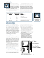
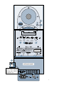
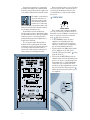
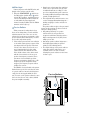
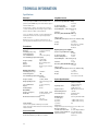
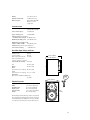
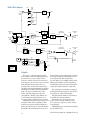
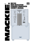
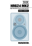
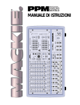
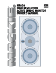
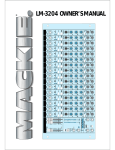
HR624
HIGH RESOLUTION
ACTIVE STUDIO MONITOR
OWNER’S MANUAL
CAUTION
AVIS
RISK OF ELECTRIC SHOCK
DO NOT OPEN
RISQUE DE CHOC ELECTRIQUE
NE PAS OUVRIR
CAUTION: TO REDUCE THE RISK OF ELECTRIC SHOCK
DO NOT REMOVE COVER (OR BACK)
NO USER-SERVICEABLE PARTS INSIDE
REFER SERVICING TO QUALIFIED PERSONNEL
ATTENTION: POUR EVITER LES RISQUES DE CHOC
ELECTRIQUE, NE PAS ENLEVER LE COUVERCLE. AUCUN
ENTRETIEN DE PIECES INTERIEURES PAR L'USAGER. CONFIER
L'ENTRETIEN AU PERSONNEL QUALIFIE.
AVIS: POUR EVITER LES RISQUES D'INCENDIE OU
D'ELECTROCUTION, N'EXPOSEZ PAS CET ARTICLE
A LA PLUIE OU A L'HUMIDITE
plugs, convenience receptacles, and the point where they exit this
Mackie product.
11. Object and Liquid Entry — Care should be taken so that
objects do not fall into, and liquids are not spilled into this Mackie
product.
12. Damage Requiring Service — This Mackie product should be
serviced only by qualified service personnel when:
A. The power-supply cord or the plug has been
damaged; or
B. Objects have fallen, or liquid has spilled into this
Mackie product; or
The lightning flash with arrowhead symbol within an equilateral
triangle is intended to alert the user to the presence of uninsulated
"dangerous voltage" within the product's enclosure, that may be
of sufficient magnitude to constitute a risk of electric shock to persons.
Le symbole éclair avec point de flèche à l'intérieur d'un triangle
équilatéral est utilisé pour alerter l'utilisateur de la présence à
l'intérieur du coffret de "voltage dangereux" non isolé d'ampleur
suffisante pour constituer un risque d'éléctrocution.
C. This Mackie product has been exposed to rain; or
The exclamation point within an equilateral triangle is intended to
alert the user of the presence of important operating and maintenance
(servicing) instructions in the literature accompanying the appliance.
Le point d'exclamation à l'intérieur d'un triangle équilatéral est
employé pour alerter les utilisateurs de la présence d'instructions
importantes pour le fonctionnement et l'entretien (service) dans le
livret d'instruction accompagnant l'appareil.
E. This Mackie product has been dropped, or its chassis
damaged.
SAFETY INSTRUCTIONS
1. Read Instructions — All the safety and operation instructions
should be read before this Mackie product is operated.
2. Retain Instructions — The safety and operating instructions
should be kept for future reference.
3. Heed Warnings — All warnings on this Mackie product and in
these operating instructions should be followed.
4. Follow Instructions — All operating and other instructions
should be followed.
5. Water and Moisture — Do not place water, hot or chilled drinks
on top of this Mackie Product as it may cause a shock hazard. This
Mackie product should not be used near water; for example, near a
bathtub, washbowl, kitchen sink, laundry tub, in a wet basement,
near a swimming pool, swamp, or salivating St. Bernard dog, etc.
6. Cleaning — Clean only with a dry cloth.
7. Ventilation — This Mackie product should be situated so that its
location or position does not interfere with its proper ventilation. For
example, the Component should not be situated on a bed, sofa,
rug, or similar surface that may block any ventilation openings, or
placed in a built-in installation such as a bookcase or cabinet that
may impede the flow of air through ventilation openings.
8. Heat — This Mackie product should be situated away from heat
sources such as radiators or other devices which produce heat.
9. Power Sources — This Mackie product should be connected to a
power supply only of the type described in these operation
instructions or as marked on this Mackie product.
10. Power Cord Protection — Power supply cords should be routed
so that they are not likely to be walked upon or pinched by items
placed upon or against them, paying particular attention to cords at
D. This Mackie product does not appear to operate
normally or exhibits a marked change in performance;
or
13. Servicing — The user should not attempt to service this
Mackie product beyond those means described in this operating
manual. All other servicing should be referred to the Mackie Service
Department.
14. To prevent electric shock, do not use this polarized plug with an
extension cord, receptacle or other outlet unless the blades can be
fully inserted to prevent blade exposure.
Pour prévenir les chocs électriques ne pas utiliser cette fiche
polariseé avec un prolongateur, un prise de courant ou une autre
sortie de courant, sauf si les lames peuvent être insérées à fond
sans laisser aucune pariie à découvert.
15. Grounding or Polarization — Precautions should be taken so
that the grounding or polarization means of this Mackie product is
not defeated.
16. Power Protection — Unplug this Mackie product during
lightning storms or when unused for long periods of time. Note that
this Mackie product is not completely disconnected from the AC
mains service when the power switch is in the OFF position.
17. This apparatus does not exceed the Class A/Class B (whichever
is applicable) limits for radio noise emissions from digital apparatus
as set out in the radio interference regulations of the Canadian
Department of Communications.
ATTENTION —Le présent appareil numérique n’émet pas de bruits
radioélectriques dépassant las limites applicables aux appareils
numériques de class A/de class B (selon le cas) prescrites dans le
règlement sur le brouillage radioélectrique édicté par les ministere
des communications du Canada.
WARNING — To reduce the risk of fire or
electric shock, do not expose this appliance to
rain or moisture.
• Please write the serial number for your studio monitor here (all
studio monitors if you have more than one) for future reference
(i.e., insurance claims, tech support, return authorization, etc.):
Monitor 1
Monitor 2
Monitor 3
Purchased at:___________________________________ Date of Purchase:_____________
Lend Me Your Ears
Exposure to extremely high noise
levels may cause permanent hearing
loss. Individuals vary considerably in
susceptibility to noise-induced hearing loss, but nearly everyone will lose
some hearing if exposed to sufficiently
intense noise for a period of time. The U.S.
Government’s Occupational Safety and Health Administration (OSHA) has specified the permissible
noise level exposures shown in this chart.
Duration Per Day
In Hours
Sound Level dBA,
Slow Response
8
6
4
3
2
1.5
1
0.5
0.25 or less
90
92
95
97
100
102
105
110
115
According to OSHA, any exposure in excess of
these permissible limits could result in some hearing loss. To ensure against potentially dangerous
exposure to high sound-pressure levels, it is recommended that all persons exposed to equipment
capable of producing these levels use hearing protectors while this unit is in operation. Ear plugs or
protectors in the ear canals or over the ears must
be worn when operating this amplification system
in order to prevent a permanent hearing loss if
exposure is in excess of the limits set forth here.
Typical
Example
Duo in small club
Subway Train
Very loud classical music
The HR624
can produce a
maximum SPL of
115 dB @ 1m
Patrice screaming at Ron about deadlines
Loudest parts at a rock concert
INTRODUCTION
To accomplish the task at hand, Greg and the
New Product Development team realized that a
commitment was required in terms of new resources
and new equipment. So we recruited some of the
best speaker and acoustic engineers in the industry to assist in the design of the HR624. And we
invested in some advanced (and need we say
expensive) measurement and analysis tools for
the design team to use.
The result? The HR624 Studio Monitors are
extremely accurate and versatile, loaded with
unique controls that allow you to fine-tune the
sound to match your individual environment
precisely. You’re gonna love these!
What are they? The Advantages...
The HR624 Studio Monitors are high-resolution,
two-way, bi-amplified, active monitors employing
a 6th-order Butterworth system with a built-in
rear-firing mass-loaded passive radiator. Whew!
There are many benefits to integrating an active
"H" Brace
Tweeter
Investments in Excellence...
crossover, power amplifiers, and drivers into a
single cabinet, and we’ve taken full advantage of
these benefits in the design of the HR624.
• The crossover point is designed so that the
high and low frequency drivers are fed only
the frequencies they are best able to reproduce.
• The amplifiers are designed to provide
maximum acoustic output from the speakers,
yet minimize the danger of speaker damage
due to overdriving.
• In addition, the amplifiers’ gain and frequency responses are individually
hand-trimmed to compensate for typical
manufacturing tolerances between the
drivers and produce a smooth frequency
response from 52Hz to 20kHz (±1.5 dB).
Woofer
Thank you for choosing Mackie Designs’
HR624 Studio Monitors. We realize that monitors
are a critically important tool whether your
application is studio recording, audio/video post
production, hi-fi, or home theater. Knowing this,
Greg Mackie had a simple mandate: Design a
reference monitor with a degree of accuracy and
versatility unmatched by any other in its size and
price category — or any size and price category
for that matter. The mandate was simple, but
accomplishing it was another story!
Figure 1. HR624 Cutaway side view
Passive Radiator
Power Amplifier/
Crossover Assembly
3
• The connecting wire between the amplifier
outputs and the drivers are kept to an
absolute minimum, so the damping factor of
the amplifier isn’t compromised by the
resistance of long speaker cables.
• The acoustic sum of the outputs from the two
drivers are optimized electronically, as well as
physically, so the amplitude response is unity
and the phase difference is minimal.
In short, all the complex interconnected
components in the system are designed to work
in harmony with each other to produce the best
possible sound.
The Transducers...
The monitors feature an 6.7-inch die-cast
magnesium frame woofer and a 1-inch viscous
edge-damped aluminum-alloy dome tweeter on
the front, and a 6-inch x 9-inch elliptical flat piston passive radiator in the back.
The high-frequency driver is mounted on a
massive, acoustically non-resonant die-cast zinc
exponential waveguide which results in wide,
controlled dispersion of high-frequency sounds.
The unique passive radiator design provides a
smooth response down to 49Hz — an astounding
accomplishment for a cabinet of this size! And
since the radiator is producing most of the sound at
the lowest frequencies, there is very little distortion
from the woofer because its cone movement is
minimal at those frequencies.
The Cabinet...
The cabinet is made of black oak veneered
MDF wood. An internal “H” brace further increases
the strength and rigidity (stiffness) of the box.
An open-cell adiabatic foam material fills the inside of the box to absorb internal reflections and
dampen standing waves.
Power Amplifiers...
The low-frequency amplifier produces up to
100 watts continuous before clipping, while the
high-frequency amplifier produces up to 40 watts
continuous.
QUICK START
We realize that you can’t
wait to hook up your new
Mackie Designs HR624
High Resolution Studio
Monitors and try them out.
Nevertheless, please take the time to read this
page NOW, and the rest can wait until you’re
good and ready.
Make sure the Voltage
on the
Selector Switch
bottom of the cabinet is set
to the correct voltage setting
for your AC Mains supply.
Each of the HR624 cabinets has its own builtin power amplifiers. That’s right, two amplifiers
per speaker cabinet; one for the high-frequency
tweeter and one for the low-frequency woofer.
You should turn the INPUT SENSITIVITY
control on the back of the cabinet down (fully
counterclockwise) before turning on the Studio
Monitors for the first time. Also be sure to set
on the front panel to its
the mute switch
standby position (in). This will prevent you
from accidentally connecting a hot signal source
to the monitors and getting a rude surprise.
There are a number of other settings you
can make on the back of the HR624, and you
can look at the graphic instructions relating to
each of them on the back of the cabinet (or
wait until you read about them later on in this
manual so you really know what they do). For
now, just leave them at the factory default set4
tings (ACOUSTIC SPACE = WHOLE; LOW
FREQ = 49Hz; HIGH FREQ = 0), except for
switch. Be sure it is set
the POWER MODE
to the STANDBY position.
1. Connect the line-level monitor signal from
your mixer, preamp, or other signal source
to the SIGNAL INPUT
jack on the
HR624 Studio Monitor (1⁄4-inch PHONE,
XLR, or RCA).
2. Connect the supplied AC power cord to the
on the back of the monitor.
IEC socket
Plug the other end into an AC outlet properly
configured with the voltage corresponding
setting.
to the Voltage Selector Switch
3. Set the POWER MODE
switch on the
rear panel to the ON position. With the
depressed, the
front panel mute switch
power amplifier is in Standby mode.
4. Start your signal source (tape deck, CD, DAW,
or whatever), but leave the master volume
control on your mixer or preamp down.
on the front of the
5. Set the mute switch
HR624 to the OUT position. The green
LED will turn on.
power
6. Slowly turn up the INPUT SENSITIVITY
control on the back of the monitor to its
fully clockwise position (NORMAL).
7. Adjust the master volume on your mixer to
a comfortably loud listening level. Enjoy
the silky smooth highs and authoritative,
commanding lows of the HR624.
Then read the rest of this manual.
FREE FIELD ACOUSTIC RESPONSE
1k
–
–10dB
OFF
QUARTER
WHOLE (NORMAL)
A
C
NORMAL
–
+1.5dB 52Hz 20kHz
49Hz
–3dB
B
80Hz
49Hz
LOW CUT
(NORMAL)
22 kHz
–3dB
–2dB
0
+2dB STANDBY
INPUT
SENSITIVITY
ACOUSTIC
SPACE
LOW
FREQ FILTER
ON
(NORMAL)
AUTO
ON
HIGH
FREQ FILTER
POWER
MODE
HALF
™
INTERNAL BI•AMPLIFICATION
100W L.F. / 40W H.F.
"MACKIE", "FR SERIES", AND THE "RUNNING MAN" FIGURE ARE REGISTERED TRADEMARKS OF MACKIE DESIGN INC.
CAUTION
WARNING:
TO REDUCE THE RISK OF FIRE OR ELECTRIC SHOCK, DO NOT
EXPOSE THIS EQUIPMENT TO RAIN OR MOISTURE. DO NOT REMOVE COVER.
NO USER SERVICEABLE PARTS INSIDE. REFER SERVICING TO QUALIFIED PERSONNEL.
RISK OF ELECTRIC SHOCK
DO NOT OPEN
SERIAL NUMBER
AVIS: RISQUE DE CHOC ELECTRIQUE — NE PAS OUVRIR
CONCEIVED AND DESIGNED BY MACKIE DESIGNS INC • WOODINVILLE • WA • USA
© 2001 MACKIE DESIGNS INC. • ALL RIGHTS RESERVED
SIGNAL INPUTS BAL /UNBAL
PHONE
XLR
MAINS INPUT
RCA
~120VAC/
~220-240VAC
50-60 Hz 130W
BOTTOM OF CABINET
120
Set the Voltage Selector
Switch to “120” for 100-120
VAC mains, and to “240” for
220-240 VAC mains.
5
AN EXTREMELY IMPORTANT NOTE
ON HR624 BASS RESPONSE AND
YOUR CONTROL ROOM.
Your new HR624s achieve
their best bass response in
a room that’s optimized for
bass reproduction. A lot of
factors can conspire to
thwart the HR624s’ extended low frequency —
including room shape, room volume and
acoustical treatment.
This is not a cop-out or an apology. It’s plain
old physics in action. Luckily we’ve armed you
with some compensating controls which you
can use to optimize the frequency response of
the speakers in your particular room. Consider
the following:
The ACOUSTIC SPACE switch
must be set correctly.
When you put your HR624s in a corner or
up against walls, their bass characteristics
change. Adjust the ACOUSTIC SPACE
switch setting accordingly to avoid muddy or
exaggerated low frequency response.
Feel free to experiment.
In many respects, every room is unique in
terms of its acoustics.
Even after you’ve read about how to set the
HR624’s rear panel switches, try other settings
to see if your particular room environment
requires different adjustments.
And, even after you’ve placed your monitors
where you think they’ll sound best, try moving
them around. You might be pleasantly surprised.
Finally, keep an open mind about
improving your room’s acoustics
and bass-handling ability.
Nobody likes to buy a new set of monitor
speakers and then be told that they should
spend extra bucks on bass traps or a remodeling
Figure 2. Horizontal Placement
6
job. But the simple fact is, “standard” rooms,
i.e. rectangular rooms in conventional business
or residential structures, are rarely if ever
conducive to optimal low bass reproduction
without some modifications.
Luckily, there are plenty of options short of
building a new control room, many of which
are covered in this manual.
Additional Tidbits of Wisdom
• When you shut down your equipment, turn
off the HR624 studio monitors first to
prevent thumps and other noises generated
by any upstream equipment from coming
out the speakers. When powering up, turn
on the monitors last.
• Save the shipping box! You may need it
someday, and you don’t want to have to pay
for another one.
• Save your sales receipt in a safe place.
• Also record all HR624 serial numbers in the
space provided on the inside front cover,
along with where and when you bought them.
Placement
The HR624s were designed to be placed in a
vertical position. If you find it necessary to
place the speakers in a horizontal position (on
their sides), place them so that the woofers are
toward the inside; that is, so the woofers are
closest to each other. This provides the best
low-frequency summing and overall imaging.
Note: The Mackie logo can be rotated 90º
so that it is oriented correctly when placing
the speakers on their sides. Gently pull out
on the Mackie emblem, rotate it, and push
it back into place.
A Few Words About THX™ pm3™
Certification
Nearly two decades ago, George Lucas
turned a passion for great sound into the
world’s most accepted and trusted solution for
achieving it. The standard was named THX
(for Tomlinson Holman, who developed the
THX Sound System when he was the research
and technical director at Lucasfilm Ltd.™ in
the early 80s), and today, with hundreds of
thousands of home theater customers and
more than 3000 THX Certified movie theaters
enjoying its benefits, the THX name has become nothing short of legendary. Simply put:
when it comes to premium sound, no other
name so closely defines ‘quality’ for millions of
movie-goers and home theater enthusiasts alike.
Today, a new landscape is emerging. A landscape comprised of hundreds of small,
professional multi-channel facilities, whose
need for differentiation, expert technical and
marketing support, and a true, multi-channel
standard is becoming a competitive fact of life.
Again, THX has a singular solution and this
time it’s called THX pm3 Certification.
All facilities involved with mixing and/or
monitoring of multi-channel material should
have the option to use pm3. THX pm3 Certification is ideal for DVD mastering, sweetening,
and mixing; and is also perfect for facilities doing work in broadcast, music, or multi-media
applications.
Contents
SAFETY INSTRUCTIONS ................................ 2
INTRODUCTION .......................................... 3
QUICK START ............................................. 4
AN EXTREMELY IMPORTANT NOTE
ON HR624 BASS RESPONSE AND
YOUR CONTROL ROOM. .............................. 6
REAR PANEL DESCRIPTION ........................... 8
SIGNAL INPUTS ............................... 8
INPUT SENSITIVITY ......................... 8
ACOUSTIC SPACE ............................ 8
LOW FREQ FILTER ........................... 9
HIGH FREQ FILTER .......................... 9
POWER MODE ............................. 10
Mains Input ................................. 11
Passive Radiator .......................... 11
FRONT PANEL DESCRIPTION ....................... 12
Mute Switch ................................ 12
OL (Overload) LED ........................ 12
PROTECTION CIRCUITS .............................. 12
Overload Protect ................................ 12
Thermal Protect .................................. 13
Integrated Magnetic Shielding ............... 13
Input Signal Wiring ............................. 13
SERVICE INFO ........................................... 14
Troubleshooting .................................. 14
Repair ............................................... 15
TECHNICAL INFORMATION ......................... 16
Specifications ..................................... 16
HR624 Block Diagram ......................... 18
Colophon ........................................... 18
Graphs .............................................. 19
HR624 THX pm3 Certification
When we submitted the HR624s for THX
pm3 Certification, they passed on the first try
with no modifications! (Celebrating with a
jumbo Bucket ‘o Popcorn with extra butter is
highly recommended!)
Anyone seeking THX Certification for their
studio, or striving to maintain THX standards,
can use the HR624s and rest assured that their
facility is in full compliance.
®
Part No. 0000626 Rev. B 2/02
©2002 Mackie Designs Inc. All Rights Reserved.
7
REAR PANEL DESCRIPTION
This is where you connect your signal to the
monitor, and make adjustments to the frequency
response of the speakers to match the monitor’s
location and your room’s environment.
For THX applications, the
rear panel switches and
controls should be set to the
THX positions as indicated
in this section.
SIGNAL INPUTS
The location of the signal input jacks makes
the connectors exit down and not straight out
the back of the enclosure. This flush-mount
design allows you to place the monitor right up
against the wall if desired.
• The XLR female, TRS female (balanced),
and RCA female (unbalanced) connectors
are included for user convenience.
• Don’t connect more than one source to the
jacks.
• Unbalanced TS (tip-sleeve) lines can be
accommodated via the TRS jack. Make sure
the cable terminates with a TS plug (like a
guitar plug), or if it’s a TRS plug (such as a
headphone plug), make sure the ring is tied
to the sleeve and that the plug is fully
inserted into the jack.
• The XLR and TRS input connectors accept
balanced or unbalanced signals. The
connectors are wired as follows (per the
AES/IEC standard):
XLR
TRS
RCA
Hot (+)
Pin 2
Tip
Tip
Cold (–)
Pin 3
Ring
—
Shield (Ground)
Pin 1
Shield Shield
• The HR624s can be used with a home
receiver even if the receiver lacks a preamp
output by using a speaker-level to line-level
signal attenuator. (See page 13 for more
information.)
8
INPUT SENSITIVITY
–10dB
OFF
NORMAL
INPUT
SENSITIVITY
THX = NORMAL
The HR624 expects a line-level signal at its
input connectors.
• The reference sensitivity is –7.5 dBu=100 dB
SPL at one meter (39 inches) with the INPUT
SENSITIVITY control set to its NORMAL
position (in other words, wide open).
• The HR624 is designed to operate with a
+4 dBu signal when the INPUT SENSITIVITY
control is in the NORMAL position.
• Refer to the QUICK START section on page 4
for the level-setting procedure.
ACOUSTIC SPACE
QUARTER
WHOLE (NORMAL)
A
C
B
HALF
ACOUSTIC
SPACE
THX = WHOLE (NORMAL)
This is a three-way switch that adjusts the
low-frequency response of the speakers to compensate for their placement in the room. See
page 5 for an overview of the rear panel.
• If you place the HR624 monitors against a
wall (half space ), set the ACOUSTIC
SPACE switch to the “B” position. This
activates a shelving filter to reduce the lowfrequency output by 2 dB to compensate for
the half-space placement.
• If you place the monitors into the corners
of your room (quarter space ), the lowfrequency output approximately doubles
from what it is in half space. Set the
ACOUSTIC SPACE switch to the “A”
position to reduce the low-frequency
output by 4 dB to compensate for the
quarter-space placement.
• If you use the HR624s free-standing, away
from walls and corners (whole space ),
set the ACOUSTIC SPACE switch to the “C”
position (NORMAL).
LOW FREQ FILTER
80Hz
49Hz
LOW CUT
(NORMAL)
the largest amount of an amplifier’s output, so
restricting the low-frequency content allows
raising the mid-frequency level somewhat. If
your client insists on mixing LOUD, this may be
a workable strategy.
HIGH FREQ FILTER
LOW
FREQ FILTER
THX = 80Hz
The LOW FREQ FILTER switch inserts a
low-frequency rolloff into the response curve.
• For some applications, the low-frequency
output of the HR624 may impair your ability
to make mix judgements.
• For THX applications, use the 80Hz setting.
• For non-THX applications where a subwoofer isn’t enhancing low frequency
output use the 49Hz (NORMAL) position.
• The LOW FREQ switch affects the lowfrequency content of your mix. Remember
how things work in reverse, so removing the
deep bass content on playback may actually
increase it in the final mix.
• You can use the LOW FREQ switch’s 80Hz
position to simulate a smaller loudspeaker,
especially one with limited low-frequency
capability (like a certain popular 2-way
nearfield monitor). You may need to do this
if a small speaker is the eventual destination of your mix, or perhaps just to see how
your mix sounds on a clock radio.
Removing the low-frequency content also
allows you to raise the overall output level
somewhat. Low-frequency information requires
–
OFF
QUARTER
WHOLE (NORMAL)
A
C
NORMAL
B
THX = 0 dB
The HIGH FREQ FILTER switch tailors the
overall high-frequency response by ±2 dB beginning at 10kHz. Leave this switch in the 0
(NORMAL) position unless:
• You want to subtly brighten or darken the
sound of the speakers.
• Perhaps you have hearing loss caused by
too many nights in front of a double
Marshall stack.
• You just like to mix on the bright side or
dull side.
If your mixes consistently sound dull or dark
when you listen elsewhere, this usually indicates
that your monitors are too bright, relative to
your normal hearing. A bit less high-frequency
energy usually fixes this, and you can force the
mix in this direction by reducing the highfrequency output of the monitors by using
the –2 dB position of the switch.
–
80Hz
49Hz
LOW CUT
(NORMAL)
ACOUSTIC
SPACE
+2dB
HIGH
FREQ FILTER
22 kHz
–3dB
–2dB
0
+2dB STANDBY
LOW
FREQ FILTER
ON
(NORMAL)
AUTO
ON
HIGH
FREQ FILTER
POWER
MODE
HALF
INPUT
SENSITIVITY
0
(NORMAL)
+1.5dB 52Hz 20kHz
49Hz
–3dB
–10dB
–2dB
™
INTERNAL BI•AMPLIFICATION
100W L.F. / 40W H.F.
"MACKIE", "FR SERIES", AND THE "RUNNING MAN" FIGURE ARE REGISTERED TRADEMARKS OF MACKIE DESIGN INC.
CAUTION
WARNING:
TO REDUCE THE RISK OF FIRE OR ELECTRIC SHOCK, DO NOT
EXPOSE THIS EQUIPMENT TO RAIN OR MOISTURE. DO NOT REMOVE COVER.
NO USER SERVICEABLE PARTS INSIDE. REFER SERVICING TO QUALIFIED PERSONNEL.
RISK OF ELECTRIC SHOCK
DO NOT OPEN
SERIAL NUMBER
AVIS: RISQUE DE CHOC ELECTRIQUE — NE PAS OUVRIR
CONCEIVED AND DESIGNED BY MACKIE DESIGNS INC • WOODINVILLE • WA • USA
© 2001 MACKIE DESIGNS INC. • ALL RIGHTS RESERVED
SIGNAL INPUTS BAL /UNBAL
PHONE
XLR
MAINS INPUT
RCA
~120VAC/
~220-240VAC
50-60 Hz 130W
9
Conversely, if your mixes are consistently
too bright, then adding some additional high
frequency energy in the monitors satisfies your
ears, and the resultant mix has less HF content.
The timbre of your monitors
affects the way that your
mixes play on other equipment. Remember that the
monitors have a mirroring
effect on the mix; if the monitors make something too loud in the mix it usually results in
not enough of that thing on tape.
Start with the response modification
switches in the factory recommended settings
(see Quick Start Section). After prolonged listening, if you notice a trend in your mixes,
perhaps making some small adjustments as
suggested here will help.
It’s a real rush to mix really loud. But remember that the resulting mix only sounds
good when you play it at least that loud. However strange it may sound, mixes made at
lower levels sound even better when played
loud; perhaps even a bit bigger than life.
HIGH RESOLUTION STUDIO MONITOR
ACOUSTIC SPACE APPLICATIONS
QUARTER SPACE
HALF SPACE
CONSOLE
CONSOLE
SPEAKERS IN CORNERS
SPEAKERS AGAINST WALL
SPEAKERS AWAY
FROM WALLS
A
B
C
WHOLE SPACE
CONSOLE
10kHz
0dB
LOW CUT
+ 2dB
–2dB
–4dB
0dB
–3dB
49Hz
80Hz
0dB
– 2dB
20
LOW FREQ
• USE 80Hz TO EMULATE SMALL SPEAKER
• USE 49Hz FOR NORMAL LOW
FREQ PERFORMANCE
100Hz
ACOUSTIC SPACE
HIGH FREQ
ROOM COMPENSATION
• 0dB (START HERE) GUARANTEED FLAT
USE FOR MOST APPLICATIONS
• +2dB: USE IF YOUR MIXES TRANSLATE BRIGHT
• –2dB: USE IF YOUR MIXES TRANSLATE DULL
FREE FIELD ACOUSTIC RESPONSE
1k
–
–10dB
QUARTER
NORMAL
22 kHz
–3dB
WHOLE (NORMAL)
A
OFF
–
+1.5dB 52Hz 20kHz
49Hz
–3dB
C
B
80Hz
49Hz
LOW CUT
(NORMAL)
–2dB
0
+2dB STANDBY
ACOUSTIC
SPACE
LOW
FREQ FILTER
ON
(NORMAL)
AUTO
ON
HIGH
FREQ FILTER
POWER
MODE
HALF
INPUT
SENSITIVITY
™
INTERNAL BI•AMPLIFICATION
100W L.F. / 40W H.F.
"MACKIE", "FR SERIES", AND THE "RUNNING MAN" FIGURE ARE REGISTERED TRADEMARKS OF MACKIE DESIGN INC.
CAUTION
WARNING: TO REDUCE THE RISK OF FIRE OR ELECTRIC SHOCK, DO NOT
EXPOSE THIS EQUIPMENT TO RAIN OR MOISTURE. DO NOT REMOVE COVER.
NO USER SERVICEABLE PARTS INSIDE. REFER SERVICING TO QUALIFIED PERSONNEL.
RISK OF ELECTRIC SHOCK
DO NOT OPEN
SERIAL NUMBER
AVIS: RISQUE DE CHOC ELECTRIQUE — NE PAS OUVRIR
CONCEIVED AND DESIGNED BY MACKIE DESIGNS INC • WOODINVILLE • WA • USA
© 2001 MACKIE DESIGNS INC. • ALL RIGHTS RESERVED
SIGNAL INPUTS BAL /UNBAL
PHONE
10
XLR
MAINS INPUT
RCA
~120VAC/
~220-240VAC
50-60 Hz 130W
Get that sound level meter out. Decide what
level you’re going to mix at and use the meter
to help keep your mixing at that level. Your
ears will thank you, and your mixes will be
better for it.
POWER MODE
STANDBY
ON
AUTO
ON
POWER MODE
This 3-position switch turns the amplifiers
on or off, or sets them to automatic mode. Use
this switch to set the HR624s to your preferred
mode of operation, and use the front panel
switch for convenience.
mute
• In the STANDBY position, the power
amplifiers are in Standby mode and
produce no sound. Low-level circuitry is
still active, but the power consumption of
the circuitry is minimal (12 watts).
• Flip the switch to the ON position and the
power amplifiers are live and operate
switch
normally. (The front panel mute
must also be OUT.)
• When it’s in the AUTO ON position, the
amplifiers turn on and off depending on the
presence or absence of an input signal. An
input signal level of –74 dBu (minimum)
activates the auto-on function. A silent
period greater than eight minutes activates
the auto-off function. The green power
LED on the front panel reflects the state of
the amplifiers.
Passive Radiator
When you mount a loudspeaker in a box,
there are two things that you can do with the
radiation from the rear of the cone: use it to
enhance the low-frequency performance of the
speaker system (bass reflex system) or soak it
up (acoustic suspension system).
• A bass reflex system uses the rear radiation
to extend the low-frequency response. Most
systems provide holes (ports) in the front
or back of the cabinet to release the rear
wave. Sometimes the holes have tubes
(ducts) in them. The dimensions of the
holes and the volume of the cabinet work
with the characteristics of the woofer to
produce low-frequency extension. These
systems are characterized by good lowfrequency performance down to the –3 dB
frequency set by the design. Below this
frequency, the frequency response falls at
24 dB/octave or more.
The HR624 is a bass reflex 6th-order system.
Rather than use ports, the vent takes the form
of a passive radiator, a mass-loaded flat piston
coupled to the air trapped within the enclosure. You can’t see the passive radiator because
it is located at the rear of the cabinet, behind
the power amplifier assembly.
Passive Radiator
Tweeter
Connect the power cord to this IEC socket, and
plug the other end into your AC outlet.
switch is in
• When the POWER MODE
switch
the ON position (and the mute
is in the OUT position), applying AC power
activates the muting circuit for about four
seconds while the power supply and
internal circuitry stabilize, then the HR624
unmutes and is ready to go.
• Simple ports or ducts must have sufficient
surface area to prevent the velocity of the
air within them from exceeding 5% of the
speed of sound, which keeps the vent from
becoming audible (breathing and wheezing
sounds) at high signal levels.
• This requirement for sufficient surface area
creates a design problem when using ports —
finding enough space in the enclosure for
them to fit.
The passive radiator replaces the port found
on most speaker systems. It offers several advantages to simple porting:
• One primary advantage of a passive
radiator is that it can reproduce low
frequencies with lower distortion and at a
higher sound pressure level (SPL) than a
simple port or duct.
• Our unique passive radiator design uses a
flat diaphragm providing exceptional
stiffness to the radiating surface.
• The elliptical shape of the passive radiator
takes up nearly the entire surface area
available on the rear of the enclosure,
allowing the passive radiator to move more
air than a port.
Woofer
Mains Input
11
FRONT PANEL DESCRIPTION
Mute Switch
STANDBY
ON
AUTO
ON
POWER
MODE
Use this switch to turn on or off the HR624
from the front. It works with the POWER
MODE
switch on the rear panel in the
following way:
• If the POWER MODE switch on the rear
panel is set to STANDBY, the front panel
switch has no effect. The power
mute
LED remains off.
• If the POWER MODE switch is ON, the
front panel mute switch turns the HR624
on or returns it to STANDBY mode, as
indicated by the power LED (the power
LED goes off when muted).
• If the POWER MODE switch is in the
AUTO ON position, the front panel mute
switch turns the HR624 on as long as there
is a signal present.
OL (Overload) LED
This LED blinks when the overload protection circuit has been triggered.
• Occasional blinking of the OL LED indicates that the loudest transients are
reaching the maximum drive capability of
the amplifiers. This is okay, although
distortion may be audible.
• Frequent or continuous blinking of the OL
LED indicates that you have exceeded the
maximum drive allowed for the speakers.
The amplifiers are clipping, and the
overload protection circuit has taken over,
reducing the input level. You should reduce
the level from your signal source until the
OL LED blinks occasionally or not at all.
PROTECTION CIRCUITS
There are a number of protection mechanisms designed into the HR624 to safeguard
the loudspeakers from inadvertent damage.
CAUTION: The protection circuits are designed to prevent damage to the loudspeakers
under reasonable and sensible conditions.
Should you choose to ignore the warning signs
(i.e., frequent Overload LED indications, excessive distortion), you can still damage the
speakers in the HR624 by overdriving them
past the point of amplifier clipping. Such damage is beyond the scope of the Warranty.
12
Overload Protect
• If you see the OL LED blinking more than
just occasionally, it’s an indication that you
should reduce the signal level coming from
your mixer or other signal source.
• The blinking OL LED indicates the driver
thermal overload protection has activated a
compressor. This reduces the input level to
the amplifiers.
• The compressor was designed to protect
the speakers and its action is highly
audible.
• The compressor was not designed for
mixing!
If a client insists on listening
to the monitors at a very
high volume, you may find
that the OL LED lights frequently. Since the majority
of the power requirement in any monitor are
the low frequencies, selectively reducing the
low end can provide a little more headroom
and volume for the monitors. Change the LOW
switch to 80Hz if necessary,
FREQ FILTER
to reduce the bass response. This may allow
the HR624s to play just enough louder to satisfy the client and to eliminate most of the
amplifier clipping.
Thermal Protect
Input Signal Wiring
All amplifiers produce heat. The HR624 is
designed to be efficient both electrically and
thermally.
• If for some reason the heatsinks get too hot,
a thermal switch activates, placing the
HR624 into Standby mode (indicated when
turns off).
the green POWER LED
• Should this happen, make sure that airflow
to the rear of the cabinet is not restricted.
• When the heatsinks cool down to a safe
temperature, the switch resets and normal
operation resumes.
You should use high-quality, shielded cable
to connect the signal source to the SIGNAL
on the HR624.
INPUT jack
• Foil shielded cables, such as Belden 8451,
8761, or 9501 are commonly used for studio
wiring.
• Microphone cables work well.
• The better the shield, the better the
immunity from externally induced noise
(like EMI and RFI). Route the cable away
from AC power cords and outlets. These are
common sources for hum in an audio
signal. Wall warts and line lumps are
especially insidious hum inducers!
You can purchase quality cables from your
Mackie dealer.
• In certain home theater applications, it
may be necessary to connect the speaker
outputs from a stereo receiver to the inputs
of the HR624s, if the receiver doesn’t have
preamp outputs or other line-level output
connections.
Integrated Magnetic Shielding
The HR624 Studio Monitor contains drivers
with large magnet structures. The drivers’ magnets are shielded to help prevent the magnetic
field from radiating out into the environment
and playing havoc with computer monitors or
TV screens. Unshielded speakers can cause
distortion in both the shape and color of the
picture if placed too close to a CRT (cathode
ray tube). If you have a particularly sensitive
computer monitor or TV screen, it may be necessary to move the speakers a few inches away.
CAUTION: Do not attempt
to connect a speaker output
directly to the input of the
HR624! Speaker levels are
much higher than line levels
and can damage the input circuitry in the HR624.
You can, however, insert a speaker-level to
line-level signal attenuator between the
receiver’s speaker output and the HR624’s input.
Your Mackie dealer may be able to help you find
one, or you can build your own. Contact our tech
support department for more information.
13
SERVICE INFO
Details concerning Warranty Service are
spelled out on the Warranty Card included with
your monitor (if it’s missing, let us know and
we’ll rush one to you).
If you think your monitor has a problem,
please do everything you can to confirm it before
calling for service, including reading through
the following Troubleshooting section. Doing
so might save you from deprivation of your
monitor and the associated suffering.
Of all Mackie products returned for service
(which is hardly any at all), roughly 50% are
coded “CND” — Could Not Duplicate, which
usually means the problem lay somewhere else
in the system. These may sound obvious to you,
but here are some things you can check:
Troubleshooting
No Power
• Our favorite question: Is it plugged in?
• Make sure the power cord is securely
and plugged
seated in the IEC socket
all the way into the AC outlet.
• Make sure the AC outlet is live (check with
a tester or lamp).
• Is the mute
switch on the front panel in
the OUT position and the POWER MODE
switch on the rear panel in the ON
position?
LED on the front panel
• Is the power
illuminated? If not, make sure the AC
outlet is live. If so, refer to “No Sound”
below.
• If the power LED is not illuminated, and
you are certain that the AC outlet is live, it
will be necessary to have the HR624
serviced. There are no user-serviceable
parts inside. Refer to “Repair” at the end of
this section to find out how to proceed.
No Sound
• Is the power
LED on the front panel
illuminated? If not, refer to “No Power”
above.
control
• Is the INPUT SENSITIVITY
turned up?
• Is the signal source turned up? Make sure the
signal level from the mixing console (or whatever device immediately precedes the studio
monitor) is high enough to produce sound.
14
• If it’s a stereo pair, try switching them
around. For example, if a left output is
presumed dead, switch the left and right
cords at the monitor end. If the problem
switches sides, it’s not the monitor. It could
be a bad cable, or no signal from the mixer.
Bad Sound
• Is the input connector plugged completely
into the jack? If using a 1⁄4” TS or TRS plug,
make sure it is plugged all the way in.
• Is it loud and distorted? Reduce the signal
level at the mixer.
• If possible, listen to the signal source with
headphones plugged into the preamp stage.
If it sounds bad there, it’s not the monitor.
• Too much bass or not enough bass? Move
around the room and see if the bass
response changes. It’s possible your
listening position coincides with a room
mode where the low frequencies either
become exaggerated or nulled. If so, try
moving the monitors to a different position,
or moving your listening position.
Noise/Hum/Buzz
• Check the signal cable between the mixer
and the monitor. Make sure all connections
are secure. These problems usually produce
crackling noises, hum, or buzz.
• If connecting an unbalanced output to the
HR624 balanced input, make sure the shield
is connected to the unbalanced ground of
the source and to pins 1 and 3 of the XLR
(or the sleeve and ring of the TRS jack).
• If a CATV cable is connected to the system,
try disconnecting it. If the hum goes away,
call your cable carrier to check for proper
grounding of the cable.
• Make sure the signal cable is not routed
near AC cables, power transformers, or
other EMI sources (including wall warts
and line lumps!). These sources usually
produce hum.
• Is there a light dimmer or other triac-based
device on the same AC circuit as the
monitor? Dimmers cause buzzing noises.
Use an AC line filter or plug the monitor
into a different AC circuit.
• Excessive hiss is an indication of an
incorrect gain setting somewhere before
the speaker.
• If possible, listen to the signal source with
headphones plugged in. If it sounds noisy
there, it’s not the monitor.
I hear sound from the monitors after I
switch the AC power off!
• Use the front panel switch to turn the
monitors on and off, or turn off the signal
going to the monitors when the AC power is
turned off.
Repair
Service for the U.S. versions of our monitors
is available only from our factory, located in
sunny Woodinville, Washington. (Service for
monitors living outside the United States can
be obtained through local dealers or distributors.) If your monitor needs service, follow
these instructions:
1. Review the preceding troubleshooting
suggestions. Please.
2. Call Tech Support at 1-800-258-6883, 7 am
to 5 pm PST, to explain the problem and
request an RA (Return Authorization)
number. Have your monitor’s serial
number(s) ready. You must have an RA
number before you can obtain service at the
factory.
3. Set aside the power cord, owner’s manual,
or anything else that you’ll ever want to see
again. We are responsible for the return of
the monitor only.
4. Pack the monitor in its original packing
box. This is very important. When you call
for the RA number, please let Tech Support
know if you need new packaging. Mackie is
not responsible for any damage that occurs
due to non-factory packaging.
5. Include a legible note stating your name,
shipping address (no P.O. boxes), daytime
phone number, RA number, and a detailed
description of the problem, including how
we can duplicate it.
6. Write the RA number in BIG PRINT on top
of the box.
7. Ship the monitor to us. We suggest insurance
for all forms of cartage. Ship to this address:
Mackie Designs
SERVICE DEPARTMENT
16140 Wood-Red Rd. NE, Suite 5
Woodinville, WA 98072
8. We’ll try to fix the monitor in three to five
business days. Ask Tech Support for current
turnaround times when you call for your RA
number. The product MUST be packaged in
its original packing box and must have the
RA number appear on the box. Once it’s
repaired, we’ll ship it back the same way in
which it was received. This paragraph does
not necessarily apply to non-warranty service.
15
TECHNICAL INFORMATION
Specifications
Enclosure
Amplifier Section
Materials and Construction:
5⁄8-inch (16mm) thick MDF construction with 1-inch
(25.4mm) thick MDF front panel with radiused edges to
minimize diffraction.
Low-frequency power amplifier:
Rated Power (at 1kHz with 1% THD):
100 watts
In Japan (100 VAC):
67 watts
Rated Load Impedance:
4 ohms
Rated THD (1W to –1 dB of rated power):
0.1 %
Slew Rate:
15V/µS
Distortion (THD, SMPTE IMD, DIM 100):
< 0.035%
Signal-to-Noise
(20Hz-20kHz, unweighted, referenced to 100W into 4Ω):
> 101 dB
Cooling:
Convection
Design:
Monolithic IC, Class AB,
Parametric Servo
Feedback
Proprietary die-cast zinc exponential wave guide for
controlled, wide dispersion from high-frequency driver.
Internal “H” brace adds to cabinet stiffness.
Open cell adiabatic “foam fill” acoustical damping material absorbs internal reflections, preventing delayed
sound coloration.
Flush-mount connector system allows monitor to be
placed against a wall without need for connector clearance.
Transducers
Low-frequency driver:
Diameter:
6.7 inches (170mm)
Sensitivity (2.83V, 1 m):
89 dB SPL
Nominal Impedance:
4Ω
Voice Coil Diameter:
1.25 inches (32mm)
Power Handling (Long Term/Program):
50/150 watts
Frequency Range:
47Hz to 6kHz
Frame:
Die Cast Magnesium
Magnet:
Ferrite
Fully shielded:
Ferrite magnet and steel
cover
High-frequency driver:
Sensitivity (2.83V, 1m):
91 dB SPL
Nominal Impedance:
6Ω
Power Handling (Long Term/Program):
20/50 watts
Frequency Range:
1.6kHz to 22kHz
Diaphragm/Suspension:
Aluminum/Impregnated
Cloth
Voice Coil Diameter:
1.0 inch (25.4mm)
Magnet:
Ferrite
Bucking Magnet:
Ferrite
High-frequency power amplifier:
Rated Power(at 1kHz with 1% THD):
40 watts
In Japan (100 VAC):
28 watts
Rated Load Impedance:
8 ohms
Rated THD (1W to –1 dB of rated power):
0.1 %
Slew Rate:
15V/µS
Distortion (THD, SMPTE IMD, DIM 100):
< 0.035%
Signal-to-Noise
(20Hz-20kHz, unweighted, referenced to 40W into 8Ω):
> 93 dB
Cooling:
Convection
Design:
Monolithic IC,
Conventional Class AB
System Specifications
Input Type:
Input Impedance:
Balanced Differential
(XLR & 1/4" TRS)
Unbalanced (RCA)
20kΩ Balanced
10kΩ Unbalanced
RFI and Level Protected
+20 dBu
80Hz, 2nd Order,
Butterworth
Shelving ±2 dB @ 10kHz
Wave Guide:
Frequency Response:
Mouth Size:
Input Protection:
Maximum Input Level:
Low Cut Frequency:
Passive Radiator:
6-inch x 9-inch (152mm x 228mm) mass-loaded
elliptical flat piston with variable thickness filleted edge
rubber surround.
HF Equalization:
Acoustic Space:
A position:
–4 dB @ 50Hz, shelving
B position:
–2 dB @ 50Hz, shelving
C position:
flat
Compressor:
Independent high and low frequency overload detection
Enclosure Alignment:
6th Order
Over Excursion Prevention: 2nd Order High-Pass Filter
Low Line Voltage Shut Down: 60% of Nominal Line
Thermal Protection:
Amplifier Shut-Down,
Auto Reset
2.5kHz to 20kHz, ±2 dB
4.3 inches diameter
(109mm)
Horizontal and Vertical Coverage:
120º, ±10º
3kHz to 20kHz
Crossover Section
Crossover Type:
Modified Linkwitz-Riley, 24 dB/octave @ 3kHz
16
Muting:
Signal Sense Threshold:
Driver Protection:
5 seconds at turn-on
–74 dBu (0.155 mV)
Independent LF and HF
Detection. Overall
Compression
Acoustic Section
Free-Field Frequency Response:
±1.5 dB, 52Hz to 20kHz
Lower cutoff frequency:
–3 dB @ 49Hz
Upper cutoff frequency:
–3 dB @ 22kHz
Sound Pressure Level at 1 meter,
–7.5 dBu into balanced input: 100 dB SPL @ 1m
Maximum peak SPL per pair: ≥ 115 dB SPL @ 1m
Maximum short term SPL on axis,
half space 80Hz to 2.5kHz:
≥ 106 dB SPL @ 1m
Residual noise (maximum gain, 600Ω source,
20Hz-20kHz bandwidth):
< 8 dB SPL @ 1m
Rated Line Input Voltage and Power:
Power consumption:
Standby mode:
12 watts
Quiescent (idle):
20 watts
Musical Program, Loud mix: 105 watts
Both channels driven into
resistive loading to 1% clipping
(LF 86W/4Ω, HF 38W/8Ω):
255 watts
12.50" (318mm)
10.38" (264mm)
US:
120 VAC, 60Hz
Europe:
240 VAC, 50Hz
Korea
(AC Power Selector at 240V): 220 VAC, 60Hz
Japan
(AC Power Selector at 120V): 100 V, 50 - 60 Hz
Rated Power
(For UL-6500, CSA-E65-94, EN-60065):
130 watts
HR624
WEIGHT
25.13 lbs.
(11.4 kg)
8.25" (210mm)
Physical Properties
Height:
Width:
Depth Enclosure:
Depth Overall:
Internal Volume:
Weight:
13.00
8.25
10.38
12.50
0.29
25.13
inches (330 mm)
inches (210 mm)
inches (264mm)
inches (318 mm)
cubic feet (8.2 liters)
lbs. (11.4 kg)
13.00"
(330mm)
Mackie Designs is always striving to improve our products
by incorporating new and improved materials, components
and manufacturing methods. Therefore, we reserve the right
to change these specifications at any time without notice.
17
HR624 Block Diagram
+15VDC
POWER
MODE
SWITCH
ON
AUTO
STANDBY
Vref
SIGNAL
SENSE
MUTE
ON/OFF
CONTROL
HIGH = MUTE OFF
LOW = MUTE ON
MUTE
THERMAL
SWITCH
POWER
LED
LOW AC
VOLTS SENSE
POWER SWITCH
(FRONT PANEL)
OVERLOAD
LED
HF OUT
UNBALANCED
LINE
INPUT
1
BALANCED
LINE
INPUTS
HF TRANSDUCER
THERMAL MODELER
HI-FREQUENCY
POWER AMPLIFIER
HIGH FREQ.
3
HI-FREQUENCY
DRIVER
CROSSOVER
+2 dB
0
–2 dB
2
HF OUT
HI-FREQ
COMPRESSOR
TWEET
LO-FREQ
SENSITIVITY
SENSITIVE
LF OUT
MUTE
LF TRANSDUCER
THERMAL MODELER
CALLOUS
ACOUSTIC
SPACE
LOW FREQ
WHOLE
49Hz (NORMAL)
HALF
QUARTER
80Hz
LO-FREQUENCY
POWER AMPLIFIER
LF OUT
LO-FREQUENCY
DRIVER
WOOF
OUTER SPACE
MOTION DETECTOR
MUTE
FUSE
BASS CONTROL SERVO LOOP
120V ↔ 240V
SENSE
RESISTOR
+
–
FUSE
TOROIDAL POWER
TRANSFORMER
MACKIE DESIGNS
HR624 THX
BLOCK DIAGRAM
(#110801DF)
HI VDC
+
LO VDC
–
Colophon
The text is a compilation based on input
from a number of sources, including design engineer Cam Jones, acoustic engineers Terry
Wetherbee, Mackie’s celebrated cerebral technical support staff, and several species of small
furry animals gathered together in a cave
grooving with a pict. Extensive input was provided from various and sundry interested parties
including our colorfully convoluted communications connoisseur and Master Geek Ron
Koliha, and Linn Compton (proofreader
extraordinaire). Finally, Jayney Wallick and
Dave Franzwa patiently patched the pieces
into perpetual prose with passionate precision.
Initially written in Microsoft® Word, the text
was imported into Adobe PageMaker®. Illustrations were produced in Adobe Illustrator®.
Most of the work was done on a Power Macintosh®
G4 with Mac OS 9.1 installed and an external
18
hamster-driven power-supply which consumed
6.7 pounds of hamster food during the production of this manual. This machine has a
PowerPC G4 processor, 384MB of RAM, a 28.62
GB internal hard drive, and an internal Sony
CD-ROM drive. This entire manual was written
and produced while sitting in a comfy chair.
The following are trademarks or registered
trademarks of Mackie Designs Inc.: The Mackie
logo, HR Series, and the Running Man.
THX pm3 and Lucasfilm are trademarks of
Lucasfilm Ltd. Used by permission.
This manual also contains names and
marks of other companies which belong to
those respective companies, and are hereby
acknowledged.
HR624 design protected under the following
patent: DES. 387,351
©2002 Mackie Designs Inc. All Rights Reserved.
Graphs
HR624 Acoustic Space Filter Response
+10
+9
+8
+7
+6
+5
+4
+3
+2
+1
dBu -0
-1
-2
-3
-4
-5
-6
-7
-8
-9
-10
20
50
100
200
500
1k
2k
5k
10k
20k
Hz
HR624 High Frequency EQ Filter Response
+10
+9
+8
+7
+6
+5
+4
+3
+2
+1
dBu -0
-1
-2
-3
-4
-5
-6
-7
-8
-9
-10
20
50
100
200
500
1k
2k
5k
10k
20k
5k
10k
20k
Hz
HR624 Low Frequency Filter Response
+10
+8
+6
+4
+2
-0
-2
-4
-6
-8
-10
-12
-14
dBu
-16
-18
-20
-22
-24
-26
-28
-30
-32
-34
-36
-38
-40
20
50
100
200
500
1k
2k
Hz
HR624 Free-Field Frequency Response
+10
+8
+6
+4
+2
-0
-2
-4
-6
-8
-10
-12
dBu
-14
-16
-18
-20
-22
-24
-26
-28
-30
-32
-34
-36
19
-38
-40
20
50
100
200
500
1k
Hz
2k
5k
10k
20k
Some of the
people at our
factory who helped
design, build, sell,
and support your
product.
®
®
™
®
Mackie Designs Inc.
16220 Wood-Red Rd. NE • Woodinville, WA 98072 • USA
US & Canada: 800/898-3211
Europe, Asia, Central & South America: 425/487-4333
Middle East & Africa: 31-20-654-4000
Fax: 425/487-4337 • www.mackie.com
E-mail: [email protected]