1
OWNER'S
MANUAL
MODEL
NO.
580.327071
®
120-240 VOLT / 8000 WATT A-C
DELUXE PORTABLE
HOURS:
Mono - Fri. 8 a.m, to 5 p.m
(CST)
CAUTION:
Read and Follow
all Safety Rules
and Instructions
Before Operating
This Equipment
SEARS,
ROEBUCK
-
Assembly
°
Operation
•
Customer
.
Service
o
Repair
and
CO.,
GENERATOR
Responsibilities
and Adjustment
Parts
Hoffman
Estates,
IL
60179
U.S.A.
SAFETY RULES
CAUTION: ALWAYS DISCONNECT SPARK PLUG WIRE AND PLACE WIRE WHERE IT CANNOT CON- ,_
TACT SPARK PLUG, TO PREVENT ACCIDENTAL STARTING WHEN SETTING UP, TRANSPORTING,
ADJUSTING OR MAKING REPAIRS TO YOUR GENERATOR
IMPORTANT
THIS GENERATOR IS DESIGNED FOR OUTDOOR USE ONLY, USING THIS GENERATOR INSIDE ANY BUILDING OR
ENCLOSURE
INCLUDING THE GENERATOR COMPARTMENT OF A RECREATIONAL VEHICLE(RV)+ IS DANGEROUS,
FIRE OR AN EXPLOSION MAY RESULT, NO USER PERFORMED MODIF CATIONS, INCLUDING VENTING OF EXHAUST
AND/OR COOLING VENTILATION, WILL ELIMINATE THE DANGER
=
=,
=
o
e
•
.
If this unit is used for backup power in the event of
a utility power failure, take the following steps: BEFORE CONNECTING THE GENERATOR TO AN
ELECTRICAL SYSTEM OPEN THE MAIN CIR+
CUlT BREAKER OR MAIN SWITCH SERVING
THE SYSTEM TO ISOLATE THE GENERATOR
SYSTEM FROM THE ELECTRIC UTILITY. FAILURE TO ISOLATE THE GENERATOR AND UTILITY SYSTEMS MAY RESULT IN DAMAGE TO
THE GENERATOR AND MAY ALSO RESULT IN
INJURY OR DEATH TO ELECTRIC UTILITY
WORKERS DUE TO BACKFEED OF ELECTRICAL ENERGY
This generator supplies dangerously high electrical
voltages Use care to prevent extremely hazardous
and possibly lethal electrical shock Never permit
any unqualified person(s) to operate or service the
unit
DO NOT operate this equipment in the rain, while
standing in water, while barefoot, or while hands or
leer are wet Dangerous electrical shock will result
The spark arrestor muffler can become extremely
hot DQ NOT operate this equipment in areas where
combustible material such as grass, leaves or paper
products can come in contact with the muffler
Maintain all wiring, extension cords, etc, in good
condition
Worn, bare, frayed, or otherwise damaged wiring and cord sets may cause dangerous
electrical shock and may also result in damage to
equipment and/or property
The National Electrical Code requires that the generator be properly connected to an approved earth
ground
Local electrical codes may also require
proper grounding of the unit See ASSEMBLY section lor more grounding information
Wire gauge sizes of wiring and cord sets must be
large enough to handle the maximum electrical load
to which they will be subjected
Most devices require cord sets rated 125 AC volts at 20 to 30
amperes or 250 AC volts at 20 amps (or greater)
Some devices may require a higher or lower rating
Refer to the Owner's manual of the electrical device
for the manufacturer's
recommendations
Cord
sets that are too small in diameter or too long will
overheat, become damaged and may cause property damage and/or electrical shock
,,_
•
The generator engine consumes oxygen and gives
off DEADLY carbon monoxide gas through its ex+
haust system. This dangerous gas, if breathed in
sufficient concentrations, can cause unconscious+
ness or even death.. Operate this equipment outdoors only, in well ventilated areas where exhaust
gases cannot accumulate and endanger people or
animals
o
WARNING: Engine exhaust from this product contains chemicals known, in certain quantities, to
cause cancer, birth defects, or other reproductive
harm
a
Gasoline is extremely FLAMMABLE and its vapors
are EXPLOSIVE
Comply with all laws regulating
the storage and handling of gasoline
DO NOT
permit smoking, open flames, sparks or heat in the
vicinity while handling gasoline
Avoid spilling
gasoline on a hot engine
DO NOT fill fuel tank
while engine is running or hot Clean off any spilled
gasoline before starting engine
= DO NOT fitl fuel tank completely full. Allow room at
top oI tank for fuel expansion or fuel may expand
and overflow onto a hot engine
a, Drain allgasoline from tankbefore transporting your
generator inside your car or other vehicle
+ DO NOT store the generator with fuel in tank where
gasoline vapors might reach an open flame, spark,
or pilot light, as on a furnace, water heater, dryer,
etc FIRE or an EXPLOSION might result
•
DO NOT insert any object or tool through cooling air
slots or openings of the engine or generator, even
if the engine is not running Damage to the unit or
personal injury may result
,= DO NOT attempt to change the engine governed
speed. Factory settings are correct when you receive the unit Excessively high engine speeds may
result ininjury or damage to equipment,
,m DO NOT use the unit if it has been damaged Repair
or replace all damaged or defective components
before you run the unit
o
DO NOT permit children to operate or service the
generator
o
Read your Owner's Manual carefully Only persons
who are familiar with these safety rules and have
been properly instructed in the use of this product
should be permitted to use the product
MEANS
"ATTENTION!!!
BECOME ALERT!!!
YOUR SAFETY IS INVOLVED."
LOOK FOR THIS SYMBOL TO POINT OUT IMPORTANT
SAFETY PRECAUTIONS.
IT
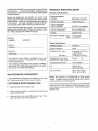
CONGRATULATIONS
on your purchase
of a Sears Craftsman Generator. It has been designed, engineered and
manufactured to give you the best possible dependability
and performance_
Should you experience any probtem you cannot easily
remedy, please contact your nearest Sears Service CentedDepartment or call the 1-800 number listed on the front
Of this rnanual. We have competent, well-trained technicians and the proper tools to service or repair this unit.
Please read and retain this manual The instructions will
enable you to assemble and maintain your generator' properly Always observe the 'SAFETY RULES"
MODEL
NUMBER
PRODUCT
Generator
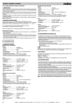
SPECIFICATIONS
Specifications
RATED MAXIMUM
POWER
8000 Watts (8.0 kW) ___
RATED VOLTAGE
!20/240 Volts a-c
RATED MAXIMUM
LOAD CURRENT
66.7/33.3 a-c amperes
RATED FREQUENCY
60 Hz at 3600 rpm
PHASE
Single Phase
BATTERY CHARGE Amps:
Volts:
10 DC amps
12 volts DC
580.327071
Engine Specifications
SERIAL
NUMBER
DATE OF
PURCHASE
ENGINE MODEL
GN-Series
DISPLACEMENT
480cc
SPARK PLUG: Type:
Champion RC12YC or
or equivalent
0.030 inch (0.76ram)
Set Gap to:
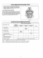
THE MODEL AND SERIAL NUMBERS WiLL BE
FOUND ON A DECAL ATTACHED TO THE GENERATOR STATOR CAN
YOU SHOULD RECORD BOTH SERIAL NUMBER
AND DATE OF PURCHASE AND KEEP IN A SAFE
PLACE FOR FUTURE REFERENCE.
MAINTENANCE
full load
5
1/2
7
GASOLINE CAPACITY
5 U.S. gallons
OIL
SAE 30 Oil
(SAE 10W-30)
OiL CAPACITY
56 oz. with oil filter
46 oz without filter
AGREEMENT
A Sears Maintenance Agreement is available on this prod _
uct Contact your nearest Sears store for details
CUSTOMER
MAXIMUM FULL TANK
OPERATING TIME (hrs)
RESPONSIBILITIES
•
Read and observe the safety rules
e
Follow regular schedule in maintaining, caring for and
using your generator
•
Follow the instructions under "Maintenance" and "Storage" sections of this Owner's Manual
NOTE: This generator is equipped with a spark arrestor
muffler The spark arrestor must be maintained in effective
working order by the owner/operator
in the State of California a spark arrestor is required by law
(Section 4442 of the California Pubiic Resources Code).
Other states may have similar laws Federal laws apply on
federal lands
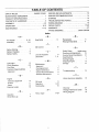
TABLE OF CONTENTS
SERVICE AND ADJUSTMENTS ......................
..............................
13
SAFETY RULES .......................................................
INSIDE COVER
MAINTENANCE
AGREEMENT ...................................................
1
SERVICE RECOMMENDATIONS
PRODUCT SPECIFICATIONS
................................................
14
..................................................
1
STORAGE ...............................................................................................
14
CONTENTS OF HARDWARE .....................................................
3
TROUBLESHOOTING
ASSEMBLY ................................................................................
4-5
POINTS .............................................
15
WIRING DIAGRAM ........................................................................
16
OPERATION .................................................................................
6-10
REPAIR PARTS .............................................................................
17-26
MAINTENANCE .........................................................................
1 I-12
WARRANTY
27
.....................................................................................
PARTS ORDERING ...............................................
BACK COVER
Index
A
-H-
Air Cleaner ...........
Assembly ..................
6, 12
4-5
-BBefore Starting ...............
Battery Charging .............
Battery Safety .................
7
9
8
Head bolts ..................
11
Idle Control ..................
8
L
Low Oil Shutdown ........
Lubrication
....
-C-
9
7, 11
M
Carburetor .............
Circuit Breakers ...........
Cord Sets ..............
Customer Responsibilites
Agreement ...............
13
4,6
4
1
Maintenance
Agreement
...............
General
Engine
Carburetor adjustment
Oil level
.
Recommendations
....
....
11
11
11
11
-O........
.........
13
!1
13
10
Oil Level
11
Operation ............
Overloading
..........
6-10
10
P
Gasoline ................
7
Grounding Lug .........
4
Parts, repair
4
11
-SSafety Rules .......... inside cover
Service and Adjustments
. 13
Service Recommendations
, 14
Specifications ....................
1
Starting Engine ...............
7
Stopping Engine .................
8
Storage .................
14
-TTroubleshooting
..............
....
17-24
15
V
Valve clearance, adjusting
.................
-G-
Receptacles .....................
Retorque head bolts ..........
I
Cleaning generator
Engine maintenance.......
Generator Maintenance
-E-
Speed .................
Electrical Loads
-R-
13
_W_
Warranty ......................
Wattage Reference Guide ,
Wiring Diagram ...........
27
10
t6
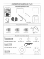
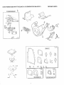
CONTENTS OF HARDWARE PACK
Parts packed
separately
in carton
IL
Accessories Carton
t_
Wheel Kit Bag
Main Unit
%Z
Support Leg
Handle
Wheels
Owner's Manual
Parts
packed
in Parts
Carton
,
Twistlock Plug
Twistlock Plug
Wheel
_,!'[
....IIllmi_
(4) Hex Head Capscrews - M8 - 45ram
(1) Hex Head Capscrews
Twistiock Plug
Kit contents
shown
Battery Charge
Cable
size
O
©
©
(8) Lock Nut - M8
Vibration Mount
(2) Washers - M8
(2) Retainer Pins
- M8 x 30mm
(2) Hex Head Capscrews - M8 x 20mm
full
%_
(2) Spacers
(2) Washers - 5/8"
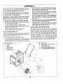
ASSEMBLY
Stand at engine end of generator and gently tilt generator forward high enough to prop up front of the cradle..
This will allow you to add the wheels,
Slide on the wheels (Item 2) on each end of the axle
and retain each with 5/8" washer (Item 10) and retaining pin (Item 4)_ Lower the generator.
Attach the vibration mount (Item '7) to the support leg
ltem 6) with M8 x 30ram capscrew (Item 8), M8 washer
Item 12) and M8 lock nut (Item 9) using the combination wrench.
With the wheels on, you can now tilt the generator end
forward and attach the support teg with two M8 x 20ram
capscrews (Item 11) and two lock nuts.
Set the generator down so it is level and, using the
combination wrench, attach the handle with four M8 x
45ram capscrews and four lock nuts
tl
Your AC generator was completely assembled at the factory tt is ready for use after it has been properly serviced
with the recommended lubricating oil and fuel.
,,
IF YOU HAVE ANY PROBLEMS WITH THE ASSEMBLY
OF YOUR GENERATOR, PLEASE CALL THE GENERATOR HELPLINE AT 1-800-222-3'136.
,,
IMPORTANT:
ANY ATTEMPT TO RUN THE ENGINE
BEFORE IT HAS BEEN SERVICED WITH THE RECOMMENDED OIL WILL RESULT IN AN ENGINE FAILURE,.
•
TO REMOVE
°
,,
°
.
=
GENERATOR
FROM CARTON
Set the carton on a fiat rigid surface with "THIS SIDE
UP" arrows pointing upward.
Carefully open the top flaps of shipping carton
Cut down comers at one end of shipping carton and lay
that side of carton down flat..
Remove packing material, carton fillers, etc
Remove generator from shipping carton
INSTALLING
WHEEL
KIT
The Sears Wheel kit was designed to greatly improve the
portability of the 8000 watt Sears Craftsman Detuxe Generator Install the Wheel Kit as follows:
=
.
Place the generator on a flat hard surface.
Slide axle (Item 3) through holes in the brackets provided on the generator cradle (Fig 1) and then add the
two spacers (item 5) on each protruding end of the axle
ITEM
1
2
3
4
5
6
7
o
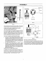
GROUNDING
THE GENERATOR
The National Electrical Code requires that the frame and
external electrically conductive pads of this generator be
properly connected to an approved earth ground. Local
electrical codes may also require proper grounding of the
unit For that purpose, a GROUNDING WING SCREW is
provided on the base of the cradle (Fig. 2 on Page 5).
Generally, connecting a No 12 AWG (American Wire
Gauge) stranded copper wire to the grounding screw and
to an earth-driven copper or brass grounding rod (electrode) provides adequate protection against electrical
DESCRIPTION
ITEM
HANDLE
WHEEL
AXLE
RETAINING PIN
WHEEL SPACER
SUPPORT LEG
VIBRAT!ON MOUNT
8
9
10
11
12
13
"l
_\_.,/
/./2
DESCRIPTION
HEX HEAD CAPSCREW, M8
LOCK NUT, M8
FLAT WASHER (WHEEL)
HEX HEAD CAPSCREW, M8
FLAT WASHER (VIBRATION
HEX HEAD CAPSCREW, M8
6
9
3
7_
_0
5
FIG. t
_.._--t2
x 30rnrn
x 20ram
MOUNT)
x 45rnm
ASSEMBLY
NEUTRAL (N)
PURCHASED
3-WtRE CORD
i_--
11A
120 VAC
HOT (H)
i
\
/--/-7/
GROUND
FIG.
FIGo 2
(G)
3
4-Wire Cord Set
shock, However, local codes may vary widely Consult with
a local electrician for grounding requirements in your area
CORD SETS AND CONNECTOR
12o VOLTS DUPLEX RECEPTACLE
PLUGS
Use only high quality, well-insulated, extension cords with
the 120-vott "duplex" type electrical receptacles,, All cord
sets used should be rated 125 volts at 20 AC amps or
greater for most electrical devices Keep extension cords
as short as possible, preferably less than I5 feet long to
prevent voltage drop and wires from overheating
t20 VOLTS, 20 AND 30 AMP RECEPTACLES:
•
For the 120 volts, 20 amp locking type NEMA L5-20R
receptacle, a well-insulated cord set wilh a NEMA
L5-20P locking type connector plug must be properly
connected to the receptacle and to the desired 120
volts, single phase, 60 Hz, AC load Cord sets should
be rated 20 AC amperes at 125 votts (or greater) for
most electrical devices (Fig 3)
°
For 120 volts, 30 amp locking type NEMA L5-30R
receptacle, a well-insulated cord set with a NEMA
L5-30P locking type connector plug must be properly
connected to the receptacle and the desired 120 volts,
single phase, 60 Hz, AC load The cord set should be
rated 30 AC amperes at 125 volts (or greater) for most
electrical devices (Fig 3)
120/240 VOLTS, 30 AMP RECEPTACLE:
A t20/240 volts, 30 amp, locking type type mating connector plug (Fig 4) is required when using this receptacle A
4-wire cord set, rated 30 AC amperes at 250 voJts (or
greater), is required and must be connected to the plug and
to the desired loads Order NEMA type L14-30P
(Hot)
Y (Hot)
/,_-/Grour}d
(Green)
FIGo 4
240 VOLTS, 50 AMP RECEPTACLE
This receptacle is rated 50 AC amperes at 250 volts You
need a 3-prong grounded connector plug with same rating
to use with this outlet Although current capacity of outlet
is rated at 50 amps, loads applied through this outlet should
not exceed 333 amps or you will overload the generator,
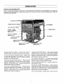
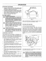
OPERATION
KNOW YOUR GENERATOR
READ THIS OWNER'S MANUAL AND SAFETY RULES BEFORE OPERATING YOUR GENERATOR, Compare the
illustrations with your generator, to familiarize yourself with the locations of various controls and adjustments, Save this
manual for future reference
AC CIRCUIT BREAKERS
ENGINE
RUN/STOP
SWITCH
CLEANER
IDLE CONTROL SWITCH
V-TWIN ENGINE
12VOLT, t0AMP
BATTERY CHARGE
RECEPTACLE
120VOLTS"DUPLEX"
RECEPTACLES
RLTER
120VOLTS, 20
RECEPTACLE
120VOLTS, 30AMi
RECEPTACLE
12(_240VOLTS,
RECEPTACLE
30AMP
ENGINE RUN/STOP SWITCH -- Must be set to RUN to
start the engine Set switch to STOP to stop the engine
120 VOLTS "DUPLEX" RECEPTACLES -- May be used
to suppIy electrical power for the operation of 120 voits at
20 amps AC, single phase, 60 Hz, AC electrical lighting,
appliance, tool and motor loads
120 VOLTS, 30 AMP RECEPTACLE -- May be used to
supply electrical power for the operation of 120 volts at 30
amps AC, single phase, 60 Hz, AC electrical lighting,
appliance, tooi and motor ioads Twistlock connectors are
required when using this receptacle
120 VOLTS, 20 AMP RECEPTACLE -- May be used to
supply electrical power for the operation of 120 volts at 20
amps AC, single phase, 60 Hz, AC electrical lighting,
appliance, tool and motor loads Twistlock connectors are
required when using this receptacle
240VOLTS, 50 AMP
RECEPTACLE
120/240 VOLTS RECEPTACLE -- May be used to supply
electrical power for the operation of up to 240 volts at 30
amps AC, single phase, 60 Hz, AC electrical lighting,
appliance, tool and motor loads Twist]ock connectors are
required when using this receptacle
AC CIRCUIT BREAKERS -- Protects the generator
against electrical ovedoad
Breakers are "push to reset"
type for 15-amp, 20-amp and 30-amp loads.
SPARK ARRESTOR MUFFLER -- Exhaust muffter has a
spark arrestor screen
240 VOLTS, 50 AMP RECEPTACLE -- May be used to
supply electrical power for the operation of up to 240 volts
at 50 amps AC, single phase, 60 Hz, AC electrical lighting,
appliance, tool and motor loads Range connectors are
required when using this receptacle
FUEL LEVEL GAUGE - Indicates level of fuel in fuel tank
OPERATION
BEFORE
STARTING
ENGINE
IF YOU HAVE ANY PROBLEMS OPERATING YOUR
GENERATOR,
PLEASE CALL THE GENERATOR
H ELPLINE AT 1-800-222"3136.
•
=
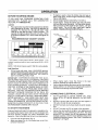
Add Oil:
=
Place generator on a level surface and remove dipstick
from extended oil fill tube. Use SAE 30 detergent oil
classified "For Service SC, SD, SE, SF, SG." SAE
!0W-30 oil may also be used. POUR SLOWLY. Oil
capacity of engine is about three (3) U.S.. pints.. When
oil is filled to dipstick FULL mark, install and tighten oil
fill plug
RECOMMENDED SAE VISCOSITY GRADES
if engine is warm, close the choke only part way or
leave it fully open° A warm engine needs less choking
than a cold engine.
Set the engine ignition switch (Fig. 7) to ON (-).
Crank engine. Grasp the starter grip and pull slowly
until you feel some resistance. Let rope return slowly,
then pull cord out with rapid full arm stroke. Let rope
return slowly
Do not let rope "snap back" against
starter. Repeat until engine starts (Fig. 8).
m
r
..........
I
_F -20
'C.30
0
-20
synthetic
-10
RANGE
TEMPERATURE
"_ Use
20
oil
having
40
0
10
ANnCIPA"fED
5W-20,
60
80
20
BEFORE
5W-30
FIGo 5
100
30
FIG. 6
40
NEXT OIL CH.ANGE
or 5W-40
viscosity
I[ not
RUN
available, a petroleum based oil may be used having 5W-20 ot 5W-30
viscosity
NOTE: 10W-40 oil may be used if 10W-30 is not available
Add Gasoline:
.
Fill fuel tank with clean, fresh, UNLEADED gasoline
Leaded REGULAR grade gasoline may also be used
DO NOT USE PREMIUM GASOLINE BE CAREFUL
NOT TO OVERFILL FUEL TANK
IMPORTANT: EXPERIENCE INDICATES THAT ALCOHOL-BLENDED FUELS (CALLED GASOHOL OR USING
ETHANOL OR METHANOL) CAN ATTRACT MOISTURE
WHICH LEADS TO SEPARATION AND FORMATION OF
ACIDS DURING STORAGE ACIDIC GAS CAN DAMAGE
THE FUEL SYSTEM OF AN ENGINE WHILE IN STORAGE TO AVOID ENGINE PROBLEMS WHEN USING
GASOHOL, THE FUEL SYSTEM SHOULD BE EMPTIED
BEFORE
STORAGE
PERIODS OF 30 DAYS OR
LONGER. DRAIN THE GAS TANK, START THE ENGINE
AND LET IT RUN UNTIL THE FUEL LINES AND CARBURETOR ARE EMPTY
USE FRESH FUEL NEXT SEASON
SEE STORAGE INSTRUCTIONS
FOR ADDITIONAL INFORMATION NEVER USE ENGINE OR CARBURETOR CLEANER PRODUCTS IN THE FUEL TANK
OR PERMANENT DAMAGE MAY OCCUR
TO START
THE
ENGINE
- Unplug all electrical loads from generator receptacles before starting the engine Never start or stop the engine with
electrical devices plugged into panel receptacles and
turned on Start, store and fuel the unit in a level position
°
°
STOP
Open the fuel shutoff valve (Fig 5)
Apply the choke (Fig 6) Pull choke lever to its FULL
CHOKE POSITION
FIG. 7
•
°
When engine starts, move the choke to the open
position gradually as engine warms up
Let the engine stabilize and warm up for a few minutes
Check that the AC ON lamp on the generator panel is
ON before connecting any electrical loads.
CONNECTING
•
°
•
,.
,,
FIG. 8
ELECTRICAL
LOADS
Use this generator to operate 120',240 volts, single
phase, 60 Hz, AC lighting, appliance, tool and motor
loads
DO NOT connect 240 volts to the 120 volts duplex or
120 volts, 20 and 30-amp receptacles
DO NOT connect any 3-phase loads to panel receptacles
DO NOT connect any 50 Hz loads to the generator
Add up the rated watts of all lights, tool, appliance and
motor loads you are powering at one time This total
should NOT be greater than (a) the generator's rated
wattage capacity, or (b) the circuit breaker rating of the
receptacle supplying power See "Don't Overload the
Generator" on Page 8
OPERATION
STOPPING
,
THE ENGINE
"12 VOLT D.C.
RECEPTACLE
Unplug all electrical loads from the generator panel
receptacles, Never start or stop the engine with elec_
trical devices plugged in and turned one
Let engine run at no-load for several minutes to stabilize the internal temperatures of engine and generator°
Set the Engine Run\Stop Switch to STOP Wait for
engine to come to a complete stop (Fig 7)
Close the Fuel Shutoff Valve (Fig 5),
°
,,
°
BATTERY
SAFETY
NEG
POS
,_
EXPLOSIVE
HYDROGEN
GAS give off EXPLOSIVE
CAUTION: Storage
batteries
hydrogen gas while charging. An exploslve mixture will remain around the battery for a long time
after It has been charged° The slightest spark can
Ignite the gas and cause an explosion. Such an
explosion can shatter the battery and cause blindness or other serious injury.
,i_
CAUTION:
DOsource
NOT permit
sparks or any
of heat smoking,
around a open
battery.flame,
DO
NOT use any lighter or other flame to provide
lighting for checking battery fluid levels. Wear
protective goggles, rubber apron and rubber
gloves when working around a battery.
CAUSTIC SULFURIC ACID
CAUTION: Battery electrolyte fluid is an extremely
caustic sulfuric acid solution that can cause severe
burns.. DO NOT permit fluid contact with eyes,
skin clothing,, etc. If spillage occurs,flush with
clear water immediately.
CHARGING
A BATTERY
12 VOLTS
BATTERY
FIG. 9
ered to be at 100% state of charge when specific gravity of
its fluid (as measured by hydrometer) is 1260
PROTECTIVE
DEVICES
LOW OIL PRESSL1RE
SHUTDOWN
A Low Oil Pressure Shutdown switch (Fig t0) on the
engine monitors low oil pressure The switch is normally
ciosed (NC), and is held open by engine oil pressure
during startup and operation Should engine oil pressure
drop below a safe value during operation, an automatic
shutdown occurs This feature protects the engine against
damaging low oil pressure conditions and possible engine
failure
Your generator has the capability of recharging a discharged, 12-volt automotive or utility style storage battery
Do not use the unit to charge any 6-volt batteries Do not
use the unit to crank an engine having a discharged battery
To recharge 12-volt batteries, proceed as follows:
,,
Check fluid level in all battery cells If necessary, add
ONLY distilled water to cover separators in battery
cells DO NOT USE TAP WATER
-
If the battery is equipped with vent caps, make sure
they are installed and are tight,
if necessary, clean battery posts or terminals
Connect battery charge cable connector plug to panel
receptacle (Fig 9) identified by the words "12-VOLT
DC"
\
Connect battery charge cable clamp with red handle to
battery post or terminal indicated by a POSITIVE, POS
FIG_ I0
•
°
,,
or (+)
-
,,
Connect battery charge cable clamp with black handle
to battery post or terminal indicated by a NEGATIVE,
NEG, or (--)
Start engine (see "Starting the Engine" on Page 5) Let
the engine run while battery recharges
When battery has charged, shut down engine (see
"Stopping the Engine" on this page)
NOTE: Use an automotive hydrometer to test battery state
of charge and condition Follow the hydrometer manulacturer's instructions carefully Generally, a battery is consid-
If the engine shuts down unexpectedly,
level before attempting a restart,
check engine oil
CAUTION!;
DO NOT ATTEMPT TO OPERATE AN
ENGINE WITH LOW OIL PRESSURE BY UNPLUGGING THE LEAD FROM THE LOW OIL PRESSURE
SWITCH OR BY BYPASSING THE SWITCH IN ANY
MANNER..
OPERATING WITH LOW OIL PRESSURE COULD DAMAGE THE ENGINE OR CAUSE
FAILURE.
OPERATION
DON'T
OVERLOAD
THE
GENERATOR
•
Some electric motors, such as inductiontypes, require
about two and a half times more watts of power for
starting than for running_ This surge of power lasts only
a few seconds when starting such motors. Make sure
you allow for this high starting wattage when selecting
electrical devies to connect to your generator. First,
figure the watts needed to start the largest motor. Add
to that figure the running watts of all other connected
loads
•
The GUIDE below is provided to assist you in determining how many items your generator' can operate at
one time..
This generator is equipped with two 20-amp, one 20-amp
and one 30-amp circuit breakers, which protect the unit
against electrical overload. Overloading a generator in
excess of its rated wattage capacity can result in damage
to the generator to connected electrical devices Observe
the following, to prevent overloading the unit:
•
=
Add up the total wattage of all electrical devices to be
connected at one time_ This total should NOT be
greater than the generator's wattage capacity.
The rated wattage of lights can be taken from light
bulbs
The rated wattage of tools, appliances and
motors can usually be found on a data plate or decal
affixed to the devicelf the appliance, toot or motor does
not give wattage, mufitpty 120 volts times ampere rating
to determine watts (volts x amps = watts).
WATTAGE
REFERENCE
GUIDE
RUNNING
RUNNING
WATTS
*Air Conditioner (12,000 Btu) ............................
Battery Charger (20 amp) .....................
Belt Sander (3") ...................................
Chain Saw ............................................
1700
500
t000
1200
Circular Saw (6-12J") ..................................... 800 to 1000
Coffee Maker'. .............................................................
1000
*Compressor (1 HP) ........................................
*Compressor (3/4 HP) ...................................
*Compressor (1/2 HP) ...............................
Curling Iron
*Deep Freeze ..........................................
Disc Sander (9") ...............................
2000
1800
1400
700
500
1200
Edge Trimmer ................................
Electric Nail Gun ..............
500
t200
Electric Range (one element) .....................
Electric Skillet ..................................
1500
1250
.................................................................
*Furnace Fan (1/3 HP) ..................................... t200
Hair Dryer ........................................................
Hand Drill (1") ................
Hedge Trimmer ...........................
t200
1100
450
WATI'S
Lawn Mower ...................................................
1200
Light Bulb ........................................................................
100
Microwave Oven .................................
700
"Milk Cooler ....................................................................
1!00
Oil Burner on Furnace .......................................
300
Oil Fired Space Heater (140,000 Btu) ................
Oil Fired Space Heater (85,000 Btu) .................
"Paint Sprayer, Airless (1/3 HP) .........................
Paint Sprayer, Airless (handheld) ..................
Radio ............................................
50 to
400
225
600
150
200
*Refrigerator ...........................................
Slow Cooker ...................................................
600
200
*Submersible Pun'lp (1-1/2 HP) ......................... 2800
*Submersible Pump (1 HP)
...........
2000
Sump Pump ....................................................
600
"Table Saw (10") ...............................
1750 to 2000
Television ...................
200 to 500
Weed Trimmer .................................................
500
* Allow 2-1/2 times the listed watts for starting these devices
CUSTOMER RESPONSIBILITIES
GENERAL
CHANGING OIL
RECOMMENDATIONS
Change oil after first 8 hours of operation. Change oi! every
50 hours thereafter. If you are using your generator under
dirty or dusty conditions, or in extremely hot weather,
change oil more often..
The Owner/Operator is responsible for making sure that all
periodic maintenance tasks are completed on a timely
basis; that all discrepancies are corrected; and that the unit
is kept clean and properly stored. Never operate a damaged or defective generator. Fo}low the recommendations
in the SERVICE RECOMMENDATIONS chart on page 9.
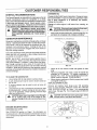
Change oil while engine is still warm from running, as
follows:
[ _k
I
CAUTION:
DISCONNECT
SPARK
PLUG
WIRE
FROM SPARK
PLUG AND PLACE
WIRE
WHERE
IT
CANNOT COME IN CONTACT WITH YOUR SPARK
PLUG BEFORE WORKING ON YOUR GENER_
ATOR,
GENERATOR
•
MAINTENANCE
CAUTION: Disconnect spark plug wire from spark 1
plug and keep It away from spark J_lU_l., .....
Clean area around oil drain plug, remove plug (Fig_ 14)
and drain oil completely into a suitable container.
EXTENDED
OIL FILL AND DIPSTICK
Generator maintenance constists of keeping the unit clean
and dry Operate and store the unit in a clean dry environment where it will not be exposed to excessive dust, dirt,
moisture or any corrosive vapors Cooling air SlotS in the
generator must not become clogged with snow, leaves,or
any other foreign material
Check the cleanliness of the generator frequently and clean
when dust, dirt, oil, moisture or other foreign substances
are visible on its exterior surface
NOTE: We DO NOT recommend using a garden hose to
clean generator Water can enter the engine fuel system
and cause problems tn additon, if water enters the generator through cooiing air slots, some of the water witt be
retained in voids and cracks of the rotor and stator winding
insulation. Water and dirt buildup on the generator internal
windings will eventually decrease the insulation resistance
of these windings
FIG. 14
,,
When all oil has drained, install and tighten oil drain
plug
o Remove oil dipstick and insert a clean fill funnel into
extended oil fill opening
Fill engine crankcase to
dipstick FULL markr Do not overfill above that mark.
About 3 pints is required POUR SLOWLY.
,, When engine crankcase is filled to proper level, install
and tighten oil fill plug
REPLACE SPARK PLUGS
TO CLEAN THE GENERATOR:
,,
=
,_
•
Use a damp cloth to wipe exterior surfaces clean
A soft, bristle brush may be used to loosen caked on
dirt, oil, etc
A vacuum cleaner may be used to pick up loose dirt
and debris
Low pressure air (not to exceed 25 psi) may be used
to blow away dirt Inspect cooling air stots and openings on the generator These openings must be kept
dean and unobstructed.
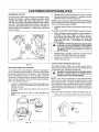
Remove and replace spark plugs every 100 operating
hours or once annually, whichever comes first See ENGINE SPECIFICATIONS on Page 1 for recommended
spark plugs Set gap (Fig 15) on spark plug to 0030 inch
(0 76ram)
CAUTION: Never insert any object or tool through
the air cooling slots, even if the engine is not
I_IL
CAUTION!
with
pen knife
DO or
NOTblast
wire brush
clean
and
spark
solvenL
plugs. Clean
result.running"
Damage to the unit or persona njury may
ENGINE
MAINTENANCE
CHECKING OIL LEVEL
See OPERATION section on Page 7 for informalion on
checking oil level Oil level should be checked prior toeach
use or at least every eight hours of operation Keep oil level
maintained
FIG. 15
I0
CUSTOMER RESPONSIBILITIES
CHANGE OIL FILTER
,,
,,
Change engine ell filter every 100 hours ef operation (every
second oil change)_ Before installing new filter, lightly
lubricate filter gasket with fresh, clean engine oil Screw
new filter on by hand until gasket contacts the filter adapter
(Fig. 16). Then tighten about 3/4 turn further. Start and run
engine for about 30 seconds, then shut down. Recheck oil
level and add oil as necessary. Finally, start engine and
,heck for leaks
Squeeze (don't twist) pre-cleaner in a clean, dry cloth
Saturate pre-cleaner in engine oil. Squeeze in a clean
absorbent cloth to remove excess oil..
NOTE: If you are going to clean the PAPER CARTRIDGE,
do not install the foam pro-cleaner and proceed to instructions for serving the paper cartridge.
•
Carefully install the foam pre-cleaner around the cartridge
To service the PAPER CARTRIDGE,
•
Clean cartridge by tapping gently on a flat surface, if
cartridge is very dirty, replace or wash in a low or
non-sudsing detergent and warm water solution.
Rinse thoroughly with flowing water from mesh side
until water runs dear.
Let cartridge dry thorougi_ly
before using.
A
=
SERVICE
ENGINE
CLEAN
=
The cover is attached to the air cleaner housing by two
latches
Lift up on the latches to unlock them, then
remove the cover.
o
Carefully remove foam pre-cleaner flora around the
cartridge
Replace pro-cleaner or wash in liquid detergent and
water.
SPARK
ARRESTER
MUFFLER
The engine exhaust muffler has a spark arrester screen
The screen should be inspected every t 00 operating hours
or once each year, whichever comes first.
AIR CLEANER
Your engine will not run properly and may be damaged if
you run it using a dirty air cleaner Clean or replace foam
pre-cleaner every 25 hours of operation Service cartridge
every 100 operating hours or once annually, whichever
comes first Clean or replace mere often if operating under
dusty er didy conditions To service the foam pre-cteaner
(Fig 17), proceed as follows:
-
CAUTIONh
NOT use
solvents
such
as kerosene DO
to clean
the petroleum
elemenL Such
solvents
will cause deterioration of the etemenL DO NOT oil
the element. DO NOT use pressure air to clean or
dry the element.
Reinstall paper cartridge, retain with cartridge retainer
and knob. Carefully install foam pre-cleaner.
Install cover assembly onto air cleaner body
Tighten latch securely
•
-
FIG. 16
proceed as follows:
A
DANGER: LET MUFFLER COOL BEFORE WORK- ]
ING ON ITo CONTACT WITH A i_OT MUFFLER OR
ENGINE CAN CAUSE SEVERE BURNS.
NOTE If you use your generator on any forest-covered,
brush covered or grass-coveted unimproved land, it must
have a spark arrester The spark arrestor must be cleaned
and maintained in good condition by the owner or operator
The preceding is required by law in the State of California
Other states may have similar taws Federal taws apply on
federal lands
Clean and inspect the spark arrestor as follows (Fig. 18):
= Remove four screws that retain the screen to muffler
LATCHES
c
KNO0 _L
'
:-_T\
SPARK__ARRESTER
_
PR_.,,CLEAN
ER
MUFFLER
FIG°17
FIGoI8
1/
SCREW
CUSTOMER RESPONSIBILmES
o
o
,,
Clean the screen with a commercial cleaning solvent.
Inspect the screen and replace if torn, perforated or
otherwise damaged. DO NOT use defective screen.
Reattach screen with four screws..
CLEAN ENGINE COOLING SYSTEM
Continued operation with a clogged engine cooling system
can cause severe overheating and possible engine damage. Fig 19 shows the blower housing removed and areas
to be cleaned. Clean these areas every 100 hours of
operation or once annually, whichever comes first.
F1G_ 19
SERVICE
RECOMMENDATIONS
HOURLY
EVERY8
HOURS OR
BEFORE USE
MAINTENANCETASK
1 Check oil bevel
OPERATING
25 HOURS OR'
YEARLY
INTERVAL
50 HOURS OR 'I100 HOURS OR
i
YEARLY
I
YEARLY
YEARLY
X
2 Change engineoil
NOTE1
i
1
NOTE2
1
NOTE2
1
NOTE3
f
3 Change oil filter
4 Service aircleaner
t
J
I
5. Cfean cooling system
6 Inspect!cleanspark arrestor and
muffler
]
;
9 Prepare for storage __
t
t
........
i
X
NOTE3
X
7 Replace/clean spark plug
8 Replacein-line [ue!filter
×
X
X
Prepare unit for storage if it is to remain idle longer than 30 days
NOTE 1: Change oil after first 8 hours, then after every 50 hours or yearly
NOTE 2: Change sooner when operating under heavy toad or high ambient temperature
NOTE 3: Ciean more often under dusty conditions or when airborne debris is present
12
X
,.................
SERVICE AND ADJUSTMENTS
ENGINE SPEED
CAUTION:
speed
was properly
adjusted at
the factory Engine
and should
require
no addittona!adjustmenL Do not attempt to change engine speed. If
you believe the engine Is running too fast or too
slow, take your generator to an authorized Sears
Service Center for repair and adjustment. CHANG_
ING ENGINE GOVERNED SPEED WILL VOID ENGINE WARRANTY.
•
tf further adjustment is needed, the main adjustment should
be made under a load condition as outlined under LOAD
ADJUSTMENT
LOAD ADJUSTMENT
•
•
•
Th speed of the generator is maintained by an electronically
controlled governor. DO NOT try to adjust the governed
speed setting for the following reasons:
•
°
°
High engine speeds are dangerous and increase the
risk of personal injury or damage to equipment.
Low engine speeds impose a heavy load on the engine
when sufficient engine power is not available and may
shorten engine life
The generator will supply correct rated AC frequency
and voltage only at the proper speed Some connected
electrical devices could be damaged by incorrect frequency and/or voltage
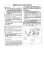
CARBURETOR
You may need to adjust the carburetor to compensate for'
differences in fuel, temperature, altitude or load
Air
cleaner and air cleaner cover must be assembled to carburetor when you run the engine
Turn the valve to mid point between rich and lean
=
•
Let engine accelerate to normal governed speed.
Apply electrical loads to the generator at or near the
unit's full rated wattage/amperage capacity.
If the engine stops or hesitates under load, open the
IDLE MIXTURE screw 1/8 turn at a time. Test each
setting with the engine under load until engine runs
smoothly.
If engine smokes excessively, turn the IDLE MIXTURE
SCREW clockwise 1/8 turn at a time until condition is
corrected
After IDLE MIXTURE SCREW is properly set, move
throttle to idle speed position. If engine does not idle
smoothly turn IDLE SPEED SCREW 1/8 turn at a time
(either direction) until engine runs smoothly
NOTE: Engines operated at altitudes at about 5000 feet or
higher may require that you install a high altitude carburetor
main jet (Part No 80883) to achieve best engine performance If engine performs erratically, contact your Sears
Service Center to install the high altitude jet
NOTE: DO NOT remove the air cleaner when running the
engine Operation without the air cleaner fully assembled
and the air filter installed may cause engine damage
INITIAL ADJUSTMENT
°
,,
=
Gently turn IDLE MIXTURE valve (Fig 20) clockwise
until it just closes DO NOT FORCE Valve may be
damaged by turning it inward too far
Next open IDLE MIXTURE valve 1-3/4 turns counterclock,vise
This initial adjustment will permit the engine to be
started and warmed up
SPEED
SCREW
FINAL ADJUSTMENT
IDLE
MIXTURE
,,
,
SCREW
Start engine and let it warm up for at least five minutes
Hold the throttle against its idle stop (idle speed) and
then turn the IDLE MIXTURE vaive slowly clockwise
1/8 turn at a time until the lean dropoff point is reached
(engine starts to miss and run erratically) Now turn the
IDLE MIXTURE valve counterc!ockwise until engine
speed begins to s!ow again (rich dropoff point)
FIG. 20
SERVICE AND ADJUSTMENTS
ENGINE
PERFORMANCE
PROBLEMS
If your engine is running below its normal performance
level, you could check for the following problems:
Check Compression:
Remove spark plug and hold thumb
over spark p_ug hole while cranking engine. Compression
should be sufficient to push thumb off the opening If
compression appears low, check for the following:
o
,,
o
Overchoking
Rich fuel mixture
Water in fuel
•
Intake valve stuck open
If plug is dry, look for the following:
,,
°
•
•
Loose cylinder head bolts.
= Blown headgasket
= Worn or damaged engine
Contact Sears Service Center to repair these problems.
Leaking carburetor gaskets
Gummy or dirty carburetor
Intake valve stuck closed
If you find any of these problems, contact your nearest
Sears Service Center
Check Ignition:
Remove spark plug wire from plug and
hold metal terminal end of wire near engine metal part.
Crank engine. If spark occurs, try a new spark plug If no
spark occurs, contact Sears Service Center.
Check Carburetion:
Make sure gas tank is filled with
clean, fresh gasoline. Make sure fuel shutoff valve is open_
Make sure fuel flows freely through fuel line between tank
and carburetor Crank engine several times, then remove
spark plug. if plug is wet, look for the following:
STORAGE
NOTE: Using a fuel additive such as Sears Craftsman ®
Fuel Stabilizer, or an equivalent, will prevent gum deposits
from forming in the generator's fuel system
GENERAL
The generator should be started at least once every seven
days and aIIowed to run at least 30 minutes If this cannot
be done and you must store the unit for more than 30 days,
use this information as a guide to prepare it for storage
STORAGE
._
o
°
INSTRUCTIONS
WARNING!
STORE
WITHPOORLY
FUEL 1N
THE
TANK NEVER
INDOORS
OR ENGINE
ENCLOSED,
VENTILATED AREAS, WHERE FUMES CAN
REACH AN OPEN FLAME_ SPARK, OR PILOT
LIGHT AS ON A FURNACE, WATER HEATER,
CLOTHES DRYER OR OTHER GAS FURNACE.
i
•
o
ENGINE:
,,
o
i,_
Run the engine for about five minutes to warm it
NOTE: If you did use "gasohol," drain fuel tank, then
run engine until engine stops from lack of fuel.
=
While engine is stil! warm, drain oil from crankcase,
Refill with fresh oil
See SPECIFICATIONS
for oil
recommendations on Page I
Remove spark plug and pour about t/2 ounce (15ml)
of engine oil into the cylinder Replace spark plug but
do not connect spark plug wire Crank slowly to distribute oil.
cranking engine slowly.
1
Install spark plug Do not connect spark plug wire.
Clean dirt, oil, and grease from cylinder, cylinder head,
fins, blower housing, rotating screen and muffler area.
Store generator in clean, dry area
GENERATOR:
TAINER OUTDOORS,
AWAY FROM OPEN FLAME,
WARNING!
DRAINISFUEL
BE
SURE ENGINE
COOLINTO APPROVED CON-
°
IMPORTANT:
EXPERIENCE INDICATES THAT ALCOHOL-BLENDED FUELS (CALLED GASOHOL OR USING
ETHANOL OR METHANOL) CAN ATTRACT MOISTURE
WHICH LEADS TO SEPARATION AND FORMATION OF
ACIDS DURING STORAGE ACIDIC GAS CAN DAMAGE
THE FUEL SYSTEM OF AN ENGINE WHILE IN STORAGE TO AVOID ENGINE PROBLEMS WHEN USING
GASOHOL, THE FUEL SYSTEM SHOULD BE EMPTIED
BEFORE
STORAGE
PERIODS
OF 30 DAYS OR
LONGER DRAIN THE GAS TANK, START THE ENGINE
AND LET IT RUN UNTIL THE FUEL LINES AND CARBURETOR ARE EMPTY
USE FRESH FUEL NEXT SEASON
SEE STORAGE iNSTRUCTIONS
FOR ADDITIONAL INFORMATION NEVER USE ENGINE OR CARBURETOR CLEANER PRODUCTS IN THE FUEL TANK
OR PERMANENT DAMAGE MAY OCCUR
o
Clean the generator as outlined on Page 9 ('q'o Clean
the Generator")
Check that cooling air slots and openings on generator
are open and unobstructed
OTHER STORAGE TIPS:
=
,,
=
I4
Do not store gasoline from one season to another.
Replace your gaso3ine can if it starts to rust Rust
and/or dirt in your gasoline can cause problems when
you use it with this unit
Do not store the generator under any plastic cover
Plastic cannot breathe, allowing moisture to form This
condensation can cause your generator to rust
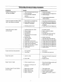
TROUBLESHOOTING
PROBLEM
Engine is running, but no
AC output is available.
POINTS
CORRECTION
CAUSE
1. One of the circuit breakers is open,
1. Reset circuit breaker.
2, Fault in generator,.
3, Poor connection or defective
2,. Contact Sears Service Department.
cord set
4. Connected device is bad.
3
Check and repair
4. Connect another device that is
in good condition.
Engine runs good at no-load but "begs
down" when loads are connected
Engine will not start; or starts
and runs rough
1. Short circuit in a connected load_
1
Disconnect shotted electrical toad
2,, Engine speed is too slow.
3 Generater is overloaded.
2
3
Contact Sears Service Departmenl
See "Don't Overload the Generato_
4
Shorted generator circuit
4
on Page 6
Contact Sears Service Department
1
RuntStop Switch set to STOP
1
Set switch to RUN
2 Dirty air cleaner
3 Out of gasoline
4 Stale gasoline
5
Spark plug wire not connected
to spark plug
6, Bad spark plug
7 Water in gasoline
80verchoking
9 Excessively rich fuel mixture
10 Intake valve stuck open or closed.
11 Engine has lost compression
12 Intake valve stuck open or closed
13 Engine compression lost
14 Failed battery
Engine shuls down during operation
Engine lacks power
1
2
Oul of gasoline
Low o11lever
4
5
Drain gas tank; fillwith fresh luel
Connect wire to spark plug
6
7
8
9
10
11.
t2
13
Replace spark plug
Drain gas tank; fill with fresh fuel
Open choke fully and crank engine
Contact Sears Service Depattment
Contact Sears Service Department
Contact Sears Service Department
Contact Sears Service Department
Contaci Sears Service Departmeni
14
Replace batter,/
1
Fill fuel tank
2
Fill crankcase to prope{ level
Load is too high
1 See "Don't Overload the Generator"
Dirtyair filter,
2
on Page 6
Reptace air fitter
1 Choke is opened too soon
1
Move choke to halfway position until
2
2
engine runs smoothly
Adjust carburetor
1
2
Engine "hunts" or fatlers
2. Clean or replace air cleanetr,
3 Fill fueltank
Carburetor
is nJnning too dch
or too _ean
No battery charge DC output [battery
will not charge)
1 Battery posts corroded
2
3
4
Battery fluid _evel tow
Battery cables are bad
Battery is defective
1 Clean battery posts
2 Add distilled water to battery
3
4
Repair or replace cable(s}.
Check battery condition, replace if
defective
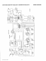
CRAFTSMAN
8000 WATT
DELUXE A-C GENERATOR
-+:+
Dt+:wmu No 925tt
16
580.327071
WIRING
DIAGRAM
CRAFTSMAN
8000 WATT DELUXE
AC GENERATOR
580.327071
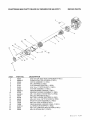
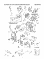
REPAIR
PARTS
22
lo
12
25
14
13
15
16
iTEM
2
3
4
5
6
7
8
9
10
11
12
13
14
15
16
!9
22
23
24
PART NO.
86307
66365-G
92553
65791
67451
51810
92350
66825-B
67022
66449-K
22097
65795
66849
66386
74908
78388
8t887-D
52618
52856
DESCRIPTION
5/16"-24 x 3/4" HEX HEAD CAPSCREW (4 REQ )
ENGINE ADAPTOR HOUSING (1 REQ )
ROTOR ASSEMBLY (1 REQ )
BALL BEARING (1 REQ)
FLAT WASHER [SPECIAL] (1 REQ)
5/16"-24 x 11" ROTOR BOLT (1 REQ)
STATOR ASSEMBLY (1 REQ)
REAR BEARING CARRIER (1 REQ )
BEARING CARRIER GROMMET (1 REQ )
M6-1 0 X 200ram STATOR BOLT (4 REQ )
M6 LOCK WASHER (4 REQ.)
BATFERY CHARGE RECTIFIER (1 REQ)
M5°0B X 16mm TAPTITE SCREW (2 REQ)
BRUSH HOLDER ASSEMBLY (1 REQ )
M5-08 X 10rnm SCREW (4 REQ.)
REAR BEARING CARRIER PANEL (1 REQ)
ALTERNATOR WRAPPER (1 REQ,,)
M5-0 8 X 12MM HEX HEAD SCREW (2 REQ )
M5-0 8 LOCKING NUT (2 REQ )
t7
D_m_l'!L' _/:" 923-N
CRAFTSMAN
8000 WATT DELUXE
A-C GENERATOR
580.328391
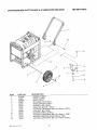
REPAIR
13
ITEM
1
2
3
4
5
6
7
8
9
10
11
12
13
Drawing
PART NO.
93393B
93682
93693B
87005
93685
93394
27007
42909
52858
22247
39253
22145
39287
Na 93_7...1
DESCRIPTION
HANDLE (1 REQ )
WHEEL (2 REQ)
AXLE (1 REQ)
RETAINING PIN (2 REQ.)
WHEEL SPACER (2 REQ )
SUPPORT LEG (! REQ.)
VIBRATION MOUNT (1 REQ)
HEX HEAD CAPSCREW, M8-1 25 X 30ram (2 REQ.)
LOCK NUT, M8 (7 REQ.)
WASHER [WHEEL] (2 REQ)
HEX HEAD CAPSCREW, M8-1 25 x 20mm (1 REQ )
WASHER [VIBRATION MOUNTING] (1 REQ.)
HEX HEAD CAPSCREW, M8-1 25 X 45ram (4 REQ )
18
PARTS
CRAFTSMAN
8000 WATT DELEUXE
A-C GENERATOR
580.327071
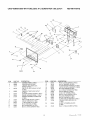
REPAIR
PARTS
20,26
ITEM
PART
I
2
3
92354
4
68759
92355
43437
68868
6
7
8
83970
93043
81434
9
10
1l
I2
I3
14
74191
87962
68337
51715
22264
43181
NO-
DESCRIPTION
DESCRIPTION
ITEM
PART NO.
CONTROL PANEL (1 REQ )
CONTROL BOX (1 REQ )
120/240V. 30 A TVVlSTLOCK
OUTLET (t RED )
120 VOLTS. 20 A DUPLEX OUTLET
15
16
17
18
19
75475
38150
23365
6682.2
43182
(1 RED )
! 20v. 30 A TWISTLOCK OUTLET
(1 REQ)
SYSTEM CONTROL BOARD (t REQ )
ENGINE HARNESS ASSM (1 REQ)
RUBBER GROMMET CONNECTOR
(1 REQ )
250V, 50 AMP OUTLET (1 REQ )
CIRCUIT BREAKER (i REQ)
20
21
22
23
24
25
26
27
75207 ÷A
78653
64526
52749
49226
23897
75207
74t 9{)
M4-0 7 x 10ram SCREW (12 REQ )
lib FLAT WASHER (12 REQ }
#8 SHAKEPROOF WASHER (12 REQ )
12V OC OUTLET & BRACKET (1 RED )
M3 LOCK WASHER (4 RED )
3Q A, CIRCUIT BREAKER (2 REQ )
ON-OFF SWITCH (1 REQ.)
#6-32 x 3/8" SCREW (8 REQ )
MS-0 8 x 12mm SCREW (4 REQ )
M5 LOCK WASHER (4 REQ )
M5 FLAT WASHER (4 REQ)
20 AMP CIRCUIT BREAKER (3 REQ )
t 20Vi20A TWtSTLOCK OUTLET
1" HEX STAND-OFF (,I REQ )
M4-0,7 HEX NUT (t2 REQ )
28
92953
_t RED.)
50-AMP, 3-TERMINAL
#8 LOCKWASHER (16 RED )
M3-0 5 x t0mm SCREW (4 RED )
29
75476
(1 REQ )
M4-O 7 x t56mm SCREW (4 REQ )
19
BLOCK
Dl,.m my N,'_ u25_'73
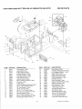
CRAFTSMAN
8000 WATT
DELUXE
AC GENERATOR
4
36
ITEM
i
2
3
4
5
6
7
8
9
1o
11
12
14
15
16
17
18
19
2o
21
22
580.32707I
REPAIR
PARTS
7
86_
31
DESCRIPTION
85_09
98216
77304
78512
80270
78299
84582
35097
7883tb
93615
92558
83465
23152
22237
22241
75246
39253
22129
92555a
86494
26850
V4win Engine (t Req )
Heat Shield (t Req )
Engine Support (2 Req,)
Alternator Support (1 Req )
Fuel Shut-off Valve (t Req )
Fuel Valve Bushing (I Req )
Fuel Tank Cap (1 Req )
Vibration Mounts (6 Req )
M6-1 0 X 60mm Capscrew
(4 Req )
Fuel Tank (1 Req )
Cradle (lreq)
Fuel Tank Mounting Grommet (4 P,eq )
3/8-16" X 3/4" Capscrew (6 Req )
3/8" Lock Washer (12 Req )
3/8-16" Hex Nu! (6 Req)
3/8-16" X lq14" Screw (4 Req )
M8-1 25 X 16ram Capscrew (2 Req )
M8 Lock Washer (2 Req)
Conlrol Panel Assembly (1 Req )
M6-I 0 X 16ram Wing Screw (1 Req)
M6 Shakeproof
PART NO.
DESCRIPTION
23
24
25
26
27
28
29
3D
31
32
143-53621
86292
23762
79661g
77581
92982
92519
92668
78837
778t 6
Ground Wire (1 Req)
#10 Self Drilling Capscrew (5 Req )
#10 Shakeproof Washer {1 Req )
35
36
37
38
39
40
41
42
43
44
45
62265
84132
93826
96409
73054
93074
98214
56892
26359
22250
86495
ITEM
PART NO.
Washer
(2 Req )
20
Engine Decal (1 Req )
Airbox V.twin Decal (1 Req )
Danger Stop Decor {1 Req )
Control Panel Decal (t Req )
Unit Decal {1 Req )
Data Plate Decal (1 Req )
Caution Hot Muffler Decal (I Req )
Rubber Grommet (1 Req )
Power Module (1 Req)
Start inslruclions
(1 Req )
-1-800" Decaf (1 Req )
Fuel Shul-off Decal (1 Req )
Heat Shield (1 Req )
Heat Shield Bracket (1 Req )
#10o24 X 3/8" Screw (5 Req )
7/16-14 X 3/4" Bolt (2 Req.,)
7/t6" Flat Washer (2 Req )
Loctite 272 Thread Locker (a/r)
Drml,ir_
No 98414
CRAFTSMAN
8000 WATT DELUXE
A-C GENERATOR
580.327071
REPAIR
PARTS
*REQUIRESSPECIALTOOLS TO INSTALL.
SEE REPAIRINSTRUCTION
MANUAL
_\
635
24
15
819
166A
',,_
__
355
///"/
_
207
(_
688
216A
2/
_
" ""+..
F,?_"
CRAFTSMAN
8000 WATT DELUXE
KZr]
_VEBHAU_.
A-C GENERATOR
580.327071
REPAIR
PARTS
_s3
851
J
GASKET SE)"]
_3
:,
_ut
i._
I014A
@
t22A
_,.
72Z
_tB7
]I6B
,,!,!_
,,,)_'_
"
!t
"
722
_171
@
537
t022
I VALVZOVERHAULHIT )
27
BREATHEB
GASKET SET
CRAFTSMAN
8000 WATT
DELUXE A-C GENERATOR
580.327071
REPAIR
PARTS
_54
S20 351
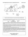
TWO-YEAR
LIMITED
WARRANTY
FOR
DELUXE
PORTABLE
GENERA
TORS
SEARS warrants to the original purchaser that the alternator and engine for its portable generator wilt be free from defects in materials or
workmanship tar the items and period set forth betow from the date o! original purchase This warranty is not transferable and applies only
to portable generators driven by the GN-Series Sears warranled engine
CONSUMER*
Alternator
Engine
COMMERCIAL*
2 years (2nd year parts only)
2 years (2nd year I:_rts only)
1 year
1 year
* NOTE: For the purpose of this warranty "'consumer use" means personal residential household use by original purchaser
"Commercial
Use" means all other uses, Including rental, construction, commercial and income producing purposes.
Once a
generator has experienced commercial use, It shall thereafter be considered a commercial use generator for the purposes of this
watt'aRty,
During said warranty period, SEARS wiff at its option_ repair or replace any part which upon examination by SEARS_ is found lo be deteclive
under normal use and service"
Slarting batteries are not warranted by SEARS All transportation costs under warranty, including return
to the lactory if necessary, are to be borne by the purchaser and prepaid by him This warranty does no! cover normal mainlenance and
service and does not apply to a generalor sol alternator or engine, or parts which have been subjected to improper or unauthorized installation
or alteration misuse, negligence accident, overloading overspeeding improper maintenance repair or storage so as in SEARS's judgment.
|o adversely affect its performance and reliability
""NORMAL WEAR: As with all mechanical devices, engines need pedodic parts service and replacement
warranty will not cover repair when normal use has exhausted the life of a part or an engine
to peform
well.
3"his
THERE IS NO OTHER EXPRESS WARRANTY. SEARS HEREBY D]SCLAfMS ANY AND ALL IMPLIED WARRANTIES, INCLUDING BUT
NOT L!MiTED TO THOSE OF MERCHANTABtUTY
AND FITNESS FOR A PARTICULAR PURPOSE TO THE EXTENT PERMITTED BY
LAW. THE DURATION OF ANY IMPLIED WARRANTIES WHICH CANNOT BE DISCLAIMED IS LIMITED TO THE TiME PERIOD AS
SPECIFIED IN THE EXPRESS WARRANTY
LIABILITY FOR CONSEQUENTIAL
INCIDENTAL OR SPECIAL DAMAGES UNDER ANY
AND ALL WARRANTIES IS EXCLUDED.
Some stales do nat allow limitalions on how long an implied warranty lasts, or the exclusion or
limitation of incidental or consequential damages, so the above limitations, or exclusions may not apply to you This warranty gives you
specific tegal rights and you may also have olher rights, which vary tram state to slate
For se_vice, see your nearesl SEARS aulhorized warranty service lacility Warranty service can be pertormed only by a SEARS authorized
service lacility
This warranty will not apply to service al any other facility At lhe time of requesling warranty service evidence of original
purchase date musl be presented
SEARS, ROEBUCK
AND CO.
Department
817 WA
23
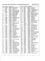
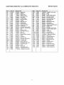
CRAFTSMAN
°EM
1
2
3
51
52
6
7
8
_A
9
10
[0A
!1
12
13
15
16A
17
t8
__0
__2
PART
DELUXE
NO.
69376
69333
67805
69311
69312
70169
69332
72301
72315
70190
70596
69336
69325
67888
80027
69315
70540
67924
67878
70166
__4
__5
26
_7
->8
_>9
32
33
34
35
39
4O
42
45
46
5O
50A
5t
67877
75248
75249
69327
75250
75251
72346
69316
69317
67816
70523
69320
70513
70584
80016
72358
69370
67290
52
53
54
55
56
57
58
59
50
B9
69A
75
87
91
95
98
t02
103
104
67895
79251
67158
79252
79253
79254
79255
79256
79257
79258
79259
67198-N
68554
7926O
79261
79262
79263
79264
79265
8000 WATT
A-C
GENERATOR
ITEM
105
108
116
116A
116B
116C
117
118
119
121
i22
125
127
130
!31
141
147
161
166
166A
167
171
t87
192
201
206
207
2O8
209
209A
216
216A
222
227
232
239
240
243
271
277
28O
3OO
300A
304
305
307
308 t
308 2
332
333
334
337
351
354
356
356A
358
363
370
423
445
DESCRIPTION
807521 -- Cylinder assembly
805107 -- Cylinder bearing
805101 -- Oil seal
807508 -- Cylinder head (cyl, #1)
807510 -- Cylinder head (cyl. #2)
+805193 -- Cylinder head washer
+805111 -- Cylinder head gasket
807553 -- Breather assembly
807795 -- Breather assembly
1"'805379 -- Breather gasket
805194 -- Breather screw
805751 -- Breather screw
805362 -- Breather tube
"805112 --Crankcase
cover gasket
805097 -- Cylinder head screw
805048 -- Oil drain plug
807625 -- Thrust washers
805213 -- Ball beating
807628 -- Crankcase cover assm
805049 -- Oil seat
805017 -- Crankase cover screw
807531 -- Magneto flywheel &
ring gear assembly
805016 -- Flywheel key
807619 -- Piston assembly
807620 -- Piston ring set
805099 -- Piston pin lock
807621 -- Piston pin assembly
807622 -- Connecting rod assembly
805395 -- Connecting rod screw
805089 -- Exhaust valve
805090 -- Intake valve
805078 -- Valve spdng
805300 -- Windage plate
805092 -- Vafve spring retainer
805161 -- Valve retainer
805354 -- Valve tappet
807764 -- Cam gear -- 2WT
805409 -- Manifold assembly --intak
805142 -- Exhaust Manifold
*805264 -- Carburetor mounting
gasket
"805023 -- Intake maniold gasket
805466 -- Screw
805006 -- Screw
492193 -- Starter housing
280918 -- Rewind starter pulley
492194 -- Rewind starter spdng
66894 -- Rope starter - cut to 69-1/2"
490653 -- Starter handle insert
490652 -- Rewind staffer handle
94464 -- Pulley washer
94462 -- Washer retainer
805007 -- Spring washer
805054 -- Governor shaft seal
807721 -- Upper carburetor body
805538 -- Valve mounting screw
807718 -- ThrottIe adjusting screw
$805541 -- intake elbow gasket
805546 -- Float assembly
$805545 -- Floating hinge pin
2-/
580.327075
_ARTNO,
79266
79267
68573
70506
70541
79268
79269
79270
79271
79272
70553
67173
79273
79274
79275
79276
79277
86443
70567
70131
75253
67885
47662-AA
75254
74946
79278
79279
79280
77348
79282
79283
79284
79285
72320
70125
60108
75213
70531
79286
67884
79288
78838
81958
69369
66886
67898
69363
69364
67890
67891
72356
72347
70116
79289
79290
79291
75258
79292
75259
66484
86444
REPAIR
PARTS
DESCRIPTION
805620Fuel inlet valve
805539 -- Choke valve
"805058 -- O-dng (oil pump)
"805198 -- O-dng (crankcase cover)
"805316O_dng (pick-up tube)
$805549 -- Main jet gasket
:1:805548 -- Main jet
$807719 -- Idle Adj Needle Valve
805540 -- Upper body mtg screw
807726 -- Carburetor overhaul kit
805328 1 Carburetor spacer
807801 -- Carburetor assembly
805559 -- Welch plug
805554 1 Throttle valve
807720 -- Throttle shaft
807722 -- Choke shaft
805553 -- Slow speed jet
807857 -- Air cleaner base assembt
805342 -- Rocker arm stud
805073 -- Oil filter adapter stud
*+805420 -- Valve cover washer
+805019 -- Nut
393815 -- Fuel hose
807623 -- Valve adjusting screw
805480 -- Choke Control Rod
805470 -- Nut tor speed control
805473 -- Speed control screw
805471 -- Speed control rod
805630 -- Governor spring - 2WT
805450 1 Governor idle spring
805439 -- Choke link
805509 -- Manual rod
807610 -- Governor control bracket
807528 -- Governor lever assembly
805465 -- Governor link spring
491657 -- OI1 pressure switch
394358 -- Fuei filter
807598 -- Oil pump pick-up screen
807609 -- Choke control bracket
805018 -- Washer
805472 -- Speed control bracket
807559 -- Exhaust Muffler
807742 -- Exhaust Muffler
807654 1 Blower housing
805406 -- Screw
805025 -- Screw
807648 -- Air guide cover (cyl #1 )
807649 -- Air guide cover (cyi #1)
805021 -- Hex nut
492341 -- Magneto armature
805407-- Mtg Screw
491055 -- Spark plug
805169 -- Hex head screw
805496 -- Nytock nut
807594 -- Ground wire (cyt #1)
807593 -- Ground wire (cyl #2)
807640 -- Gasket set
19203 -- Flywhee! puller
805484 -- Breather screw -- washe_
805260 -- Screw
394018 -- Air cleaner cartridge
CRAFTSMAN
EM
55
56
59
31
37
t5
t 5A
2O
->3
24
->5
35
37
39
52
52A
32
72
73
31
38
I3
t4
t6
34
_4A
34B
35
-'12
43
57
38
t8
t8A
22
PARTNO.
70t98-A
79293
79294
79295
86445
79298
79299
70520
70158
67181
70151
86446
66480
80002
72361
72362
80003
70199
69368
72321
70162
70197
69397
72366
72367
72365
80004
80005
70562
86447
86448
67820
80006
68555
67806
75262
8000 WATT A-C GENERATOR
580.327074
DESCRIPTION
805153 -- Starter hub
224228 -- Retainer
492341 -- Starter dog
94463 -- Retainer SCrew
491875 -- Air Cleaner Knob
262565 -- Dog spring
262564 -- Torsion spnng
807527 -- Ground terminal
807585 -- Dipstick
805259 -- Filler tube seal
807584 -- Oil filler tube
271271 -- Foam Element
805003 -- Air cleaner gasket
221372 -- Fdction clip
805412 -- Governor shaft bushing
805413 -- Governor shaft bushing
805381 -- Bolt
805197 -- Breather baffle
807655 -- Back plate assembly
805383 -- Hex nut
93053 -- Hose clamp
491017Rewind starter assembly
805158 i Screw
805417 -- Cotter pin
807596 -- Governor fork
805416 -- Governor shaft washer
$805557 -- Throttle collar
$805543 -- Choke collar
805529 -- Spark plug elbow
807862 -- Air cleaner cover assm
805631 -- Air cleaner plate
805009 -- Screw
805485 -- Spring cap
805103 -- Crankcase dowel
805102 -- Cylinder head dowe!
1-'805482 -- Brealher screw seal
ITEM
722A
819
842
851
862A
864
866
868
869
870
871
879
883
884
955
971
978
982
987
1004A
1014A
1022
1023
1024
1025
1026
1026A
1027
1028
1029
103O
1031
1033
1036
25
PART NO.
75263
68572
80007
75272
86449
67195
723O7
70122
67910
67911
67813
72304
67897
74807
8OO08
67156
68548
68527
80010
86450
86451
67920
69328
70539
70536
70577
80009
70185
70514
70599
70567
70566
75271
80012
REPAIR
PARTS
DESCRIPTION
t'805483 -- Breather screw seal
805057 -- Screw
805386 -- O-ring
493880 -- Ignition cable terminal
807796 -- Air cleaner bracket
805083 -- Exhaust port liner
807652 -- Air guide valley cover
805094 -- Vafve guide sea!
805085 -- Intake valve
805086 -- Exhaust valve seat
805084 -- Valve guide
805369 -- Carburetor cover
"805024 -- Exhaust manifold gasket
807595 -- Muffler clamp
807723 -- Jet plug
805405 -- Air cleaner base screw
"805250 -- Oil filter adapter gasket
805030 -- Screw
$805544 -- Shaft seal
805632 -- Air inlet tube
807797 -- Breather deflector
+'805028 -- Valve cover gasket
805100 -- Valve cover
807644 -- Oil pump assembly
805313 -- Governor slider
805352 -- Rod intake push
8056!7Rod exhaust push
491056 -- 011filler
805292 -- Oil filter adapter
807557 -- Rocker arm
805342 -- Rocker arm shaft
805341 -- Rocker arm support
807668 -- Valve overhaul kit
808688 -- Breather gasket set
CRI:IFTSMRN°
OWNER'S
MANUAL
120-240
VOLTS
DELUXE
/ 8000 WATT
PORTABLE
A-C
GENERATOR
Each Generator has its own model number,, Each engine has its own
model number,
MODEL NO.
580_327071
The model number for your generator will be found on a decal attached to
the unit
The model number for the engine will be found on the Blower Housing of
the engine adjacent to the spark plug,
All parts listed herein may be ordered through Sears, Roebuck and Co..
Service Centers and most Retail Stores
IF YOU NEED
REPAIR
SERVICE
OR PARTS
WHEN ORDERING
REPAIR
LOWING INFORMATION:
e
FOR REPAIR SERVICE CALL
THIS TOLL FREE NUMBER
1-800-44:_ E PAl R
PRODUCT--
PARTS,
DELUXE
•
MODEL
NUMBER
®
PART NUMBER
®
PART DESCRIPTION
ALWAYS
PORTABLE
GIVE
THE
FOL-
GENERATOR
-- 580.327071
(1-800-473-7247)
FOR REPLACEMENT PARTS
INFORMATION AND ORDER _
ING, CALL THIS TOLL FREE
NUMBER:
1-800-FON-PART
(I -800-366-7278)
SEARS,
Pat1 No
91,;J]]
R_
ROEBUCK
i_iol!
i) f I _Jbi95}
Your Sears merchandise has added value when you consider that Sears
has service units nationwide staffed with Sears trained technicians..professional technicians specifically trained on Sears products, having the
parts, tools and the equipment to ensure that we meet our pledge to you,
we service what we sell
and
CO.,
Hoffman
Estates,
IL
60179
U.S.A.
['rit_t .,:,:J i_; U 2, A