1
O P E R A T I N G I N S T R U C T I O N S
BEDIENUNGSANLEITUNG / ISTRUZIONI PER L’USO / INSTRUCCIONES DE USO
MASTER VOLUME
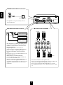
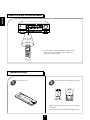
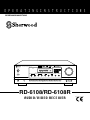
AUDIO/VIDEO RECEIVER RD-6108R
MAIN POWER
REMOTE
SENSOR
RDS EON TA TP PTY ST TUNED
TAPE
M
dB
kHz
MHz
DTS
ON/
DIGITAL
Pro Logic
THEATER
HALL
EON PTY
EON TA
DISPLAY
PTY SELECT
SEARCH
PRESET
MEM
TONE
DIRECT
ms
SLEEP
OFF
INPUT SELECTOR
STANDBY
AUDIO
VIDEO
TAPE MON.
SURROUND MODE
6CH DIRECT
AUTO
DSP MODE
STEREO
DIGITAL
INPUTS
TONE
DIRECT
ON/STANDBY
VIDEO 3
PHONES
SPEAKER
CHANNEL
SELECTOR
ADJUST
TONE MODE
SPEAKER
MODE
DYNAMIC
RANGE
CINEMA EQ
MEMO/ENTER
TUNING/PRESET
T/P MODE
FM MODE
BAND
ON/OFF
VIDEO
L - AUDIO - R
RD-6108/RD-6108R
AUDIO/VIDEO RECEIVER
Introduction
ENGLISH
UNPACKING AND INSTALLATION
Congratulations on Your Purchase!
Your new high fidelity receiver is designed to deliver
maximum enjoyment and years of trouble free service.
Please take a few moments to read this manual
thoroughly. It will explain the features and operation of
your unit and help ensure a trouble free installation.
Please unpack your unit carefully. We recommend that
you save the carton and packing material. They will be
helpful if you ever need to move your unit and may be
required if you ever need to return it for service. Your unit
is designed to be placed in a horizontal position and it is
important to allow at least two inches of space behind
your unit for adequate ventilation and cabling
convenience.
To avoid damage, never place the unit near radiators, in
front of heating vents, in direct sunlight, or in excessively
humid or dusty locations. Connect your complementary
components as illustrated in the following section.
CAUTION
RISK OF ELECTRIC SHOCK
DO NOT OPEN
CAUTION : TO REDUCE THE RISK OF
ELECTRIC SHOCK, DO NOT
REMOVE COVER (OR BACK).
NO USER-SERVICEABLE PARTS
INSIDE. REFER SERVICING TO
QUALIFIED SERVICE PERSONNEL.
This symbol is intended to alert the user to the
presence of uninsulated "dangerous voltage"
within the product's enclosure that may be of
sufficient magnitude to constitute a risk of
electric shock to persons.
This symbol is intended to alert the user to the
presence of important operating and
maintenance (servicing) instructions in the
literature accompanying the appliance.
WARNING
To reduce the risk of fire or electric shock, do not expose
this appliance to rain or moisture.
FOR U.S.A
Note to CATV System Installer: This reminder is
provided to call the CATV system installer's attention
to Article 820-40 of the NEC that provides guidelines
for proper grounding and, in particular, specifies that
the cable ground shall be connected to the
grounding system of the building, as close to the
point of cable entry as practical.
FCC INFORMATION
This equipment has been tested and found to
comply with the limits for a Class B digital device,
pursuant to Part 15 of the FCC Rules. These limits
are designed to provide reasonable protection
against harmful interference in a residential
installation. This equipment generates, uses and can
radiate radio frequency energy and, if not installed
and used in accordance with the instructions, may
cause harmful interference to radio communications.
However, there is no guarantee that interference will
not occur in a particular installation. If this equipment
does cause harmful interference to radio or
television reception, which can be determined by
turning the equipment off and on, the user is
encouraged to try to correct the interference by one
or more of the following measures:
Reorient or relocate the receiving antenna.
Increase the separation between the equipment
and receiver.
Connect the equipment into an outlet on a circuit
different from that to which the receiver is
connected.
Consult the dealer or an experienced radio/TV
technician for help.
CAUTION: Any changes or modifications in
construction of this device which are not expressly
approved by the party responsible for compliance
could void the user's authority to operate the
equipment.
Caution regarding placement
(Except for U.S.A and Canada)
To maintain proper ventilation, be sure
to leave a space around the unit (from
the largest outer dimensions including projections)
equal to, or greater than, shown below.
Left and right panels: 5 cm
Rear panel: 10 cm
Top panel: 20 cm
Caution : Do not block ventilation openings or stack
other equipment on the top.
2
FOR U.S.A AND CANADA ..............................120 V
FOR OTHER COUNTRIES ................... 115 V/230 V
FOR YOUR SAFETY
FOR YOUR SAFETY
Units shipped to the U.S.A and Canada are designed
for operation on 120 V AC only.
Units shipped to countries other than the above
countries are equipped with an AC voltage selector
switch on the rear panel. Refer to the following
paragraph for the proper setting of this switch.
Safety precaution with use of a polarized AC plug.
However, some products may be supplied with a
nonpolarized plug.
AC VOLTAGE SELECTION
This unit operates on 115/230 V AC. The AC voltage
selector switch on the rear panel is set to the voltage
that prevails in the area to which the unit is shipped.
Before connecting the power cord to your AC outlet,
make sure that the setting position of this switch
matches your line voltage. If not, it must be set to
your voltage in accordance with the following
direction.
CAUTION : To prevent electric shock, match wide
blade of plug to wide slot, fully insert.
FOR EUROPE AND AUSTRALIA .........230 V/240 V
FOR YOUR SAFETY
Units shipped to Australia are designed for operation
on 240 V AC only.
To ensure safe operation, the three-pin plug supplied
must be inserted only into a standard three-pin
power point which is effectively earthed through the
normal household wiring. Extension cords used with
the equipment must be three-core and be correctly
wired to provide connection to earth.
Improper extension cords are a major cause of
fatalities. The fact that the equipment operates
satisfactorily does not imply that the power point is
earthed and that the installation is completely safe.
For your safety, if in any doubt about the effective
earthing of the power point, consult a qualified
electrician.
PAN-EUROPEAN UNIFIED VOLTAGE
All units are suitable for use on supplies 230~240 V
AC.
AC voltage selector switch
AC 230 V
AC 115 V
Move switch lever to match your line voltage with a
small screwdriver or other pointed tool.
3
ENGLISH
READ THIS BEFORE OPERATING YOUR UNIT
ENGLISH
CONTENTS
Introduction
UNPACKING AND INSTALLATION ....................................................................................................... 2
READ THIS BEFORE OPERATING YOUR UNIT................................................................................... 3
System Connections ........................................................................................................................................ 5
Front Panel Controls ...................................................................................................................................... 8
DIGI LINK III System Remote Controls.................................................................................................. 9
REMOTE CONTROL OPERATION RANGE.......................................................................................... 10
LOADING BATTERIES............................................................................................................................ 10
Operations
LISTENING TO A PROGRAM SOURCE................................................................................................ 11
SURROUND SOUND................................................................................................................................ 14
ENJOYING SURROUND SOUND........................................................................................................... 16
LISTENING TO RADIO BROADCASTS ................................................................................................ 20
LISTENING TO RDS BROADCASTS(FM only)
(Additional Function for RD-6108R RDS Tuner Only)............................................................................. 22
RECORDING ............................................................................................................................................. 24
OTHER FUNCTIONS................................................................................................................................ 25
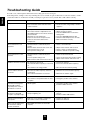
Troubleshooting Guide ................................................................................................................................ 26
Specifications .................................................................................................................................................. 27
4
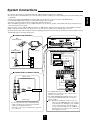
Do not plug the AC input cord into the wall AC outlet until all connections are completed.
Be sure to connect the white RCA pin cord to the L(left) and the red RCA pin cord to the R(right) jacks when making audio
connections.
Change the position of the FM indoor antenna until you get the best reception of your favorite FM stations.
A 75 Ω outdoor FM antenna may be used to further improve the reception.
Disconnect the indoor antenna before replacing it with the outdoor one.
Place the AM loop antenna as far as possible from the receiver, TV set, speaker cords and the AC input cord and set it to a
direction for the best reception.
If the reception is poor with the AM loop antenna, an AM outdoor antenna can be used in place of the AM loop antenna.
Make connections firmly and correctly. If not, it can cause loss of sound, noise or damage to the receiver.
If the electricity fails or the AC input cord is left unplugged for more than 2 weeks, the memorized contents will be cleared.
Should this happen, memorize them again.
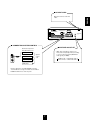
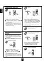
■ CONNECTING ANTENNAS
FM
MANUFACTURED UNDER LICENSE FROM DIGITAL THEATER SYSTEMS,INC.
US PAT. NO. 5,451,942, 5,956,674, 5,974,380, 5,978,762 AND OTHER WORLD-WIDE
PATENTS ISSUED AND PENDING. "DTS" AND "DTS DIGITAL SURROUND" ARE
REGISTERED TRADEMARKS OF DIGITAL THEATER SYSTEMS, INC.
COPYRIGHT 1996, 2000 DIGITAL THEATER SYSTEMS, INC. ALL RIGHTS RESERVED.
AVIS : RISQUE DE CHOC ELECTRIQUE-NE PAS OUVRIR.
WARNING : SHOCK HAZARD-DO NOT OPEN.
WARNING : TO REDUCE THE RISK OF FIRE OR ELECTRIC SHOCK,
DO NOT EXPOSE THIS APPLIANCE TO RAIN OR MOISTURE.
(OUTDOOR ANTENNA)
AM
LOOP
6-CH DIRECT INPUT
CENTER
SUB
WOOFER
SER. NO
AC INPUT
230V~50Hz
200W
MODEL NO. RD-6108R
AUDIO/VIDEO RECEIVER
DESIGNED IN USA
ASSEMBLED IN CHINA
DIGITAL IN
PRE OUT
OPTICAL
COAX 1
COAX 2
AC OUTLET
SUB
WOOFER
CD
FM
75Ω
TAPE MON.
VIDEO 1
VIDEO 2
VIDEO
IN
VIDEO
OUT
VIDEO 2
MONITOR
MANUFACTURED UNDER LICENSE FROM DOLBY
LABORATORIES. “DOLBY”, “PRO LOGIC”, AND
THE DOUBLE-D SYMBOL ARE TRADEMARKS OF
DOLBY LABORATORIES.
L
DIGI
-LINK
L
R
ANTENNA
R
FRONT
FM
AUX
PLAY
REC
PLAY
REC
PLAY
SWITCHED
230V~50Hz
100W MAX
VIDEO 1
VIDEO 1
■ CONNECTING AUDIO/VIDEO COMPONENTS
AM loop antenna
(INDOOR ANTENNA)
REAR
VIDEO OUT
VIDEO IN
Monitor TV
VIDEO IN
300 ohm
feeder
DVD player or additional video component
AM
LOOP
VIDEO OUT
AUDIO OUT
MULTIPLE COMPACT DISC PLAYER CDC-5080R
POWER
ON/OFF
Video deck 1
POWER
MULTIPLE COMPACT DISC PLAYER CDC-5080R
ON/OFF
V-CD
PBC
GRAPHICS
OPEN/CLOSE
1
2
REVERT
PEAK
3
4
PROG
AUTO
DELETE
EDIT
A
B
RANDOM
SCENE TRACK
INDEX
5
REPEAT ALL 1 DISC S
A< >B MPX INTRO
STEP
1
4
7
10
13
2
3
5
6
8
9
11 12
14 15
PHONES LEVEL
PHONES
MIN
MAX
AUDIO IN
AUDIO OUT
SUPPLIED ADAPTOR
CD
■ CONNECTING 6 CH DIRECT INPUTS
AUX
TAPE MON.
PLAY
VIDEO 1
REC
PLAY
VIDEO
IN
VIDEO
OUT
VIDEO 2
VIDEO 2
MONITOR
PLAY
VIDEO 1
VIDEO 1
REC
CENTER CH OUT
REC(LINE IN)
SUBWOOFER CH OUT
*Tape deck or graphic equalizer
DIGI-LINK STEREO DOUBLE CASSETTE DECK DD-5080C
COUNTER
RESET
A/B
MODE
BC
HIGH NORM
CD SYN
M
MPX
MIN
RELAY P
T SIZE
SEC
MEMORY
B/C/OFF
REC
REC
REVERSE
R PLAY
L
dB
-00
-20
-10
-6
-3
0
+3
+6
R
AUTO REVERSE
DUBBING
EJECT
NORMAL
PLAY/AUTO TAPE SELECTOR
O/O
POWER
6-CH DIRECT INPUT
AUTO REVERSE
CD SUN REC
HIGH
AMS
B
AMS
PHONES
REC LEVEL
PLAY(LINE OUT)
0
L
HX-PRO
A
REC BALAMCE
10
MIC MIX
R SOURCE
RECORD & PLAY/AUTO TAPE SELECTOR
MIC
MIC
CD player
MULTIPLE COMPACT DISC PLAYER CDC-5080R
CENTER
SUB
WOOFER
OPEN/CLOSE
V-CD
PBC REVERT PROG
GRAPHICS
POWER
PEAK
DELETE
ON/OFF
1
2
3
4
AUTO
EDIT
A
B
RANDOM REPEAT ALL 1 DISC S
A< >B MPX INTRO
SCENE TRACK
INDEX STEP
5
1 2 3
4 5 6
7 8 9
10 11 12
13 14 15
PHONES LEVEL
REMOTE SENSOR
PROGRAM/REVIEW RANDOM
REPEAT
MIN
MAX
PHONES
Tape deck or additional audio component
REAR
CH OUT
L
DIGI-LINK STEREO DOUBLE CASSETTE DECK DD-5080C
RESET
PLAY(LINE OUT)
MIN
RELAY P
T SIZE
SEC
A/B
MEMORY
MODE
B/C/OFF
REC
REVERSE
R PLAY
-00
-20
-10
-6
-3
0
+3
+6
DUBBING
O/O
AUTO REVERSE
CD SUN REC
HIGH
AMS
B
POWER
AMS
PHONES
REC LEVEL
0
10
REC BALAMCE
L
A
MIC MIX
R SOURCE
HX-PRO
RECORD & PLAY/AUTO TAPE SELECTOR
MIC
MIC
• The VIDEO 2 jacks may also be connected to an
additional video component such as a cable TV tuner, a
LD player or satellite system.
• The TAPE MONITOR PLAY/REC jacks may also be
connected to the LINE OUT/IN jacks of an optional
graphic equalizer.
Note : When Sherwood DVD player such as V-756, etc. is
connected to the DIGI LINK jack for system control,
you should connect the DVD player to the "VIDEO
2" jacks of this unit. Because, if the PLAY button,
etc. is pressed on the DVD player, the "VIDEO 2" is
automatically selected as an input source on this unit
and the playback, etc. starts.
R
FRONT
M
MPX
REC
L
R
EJECT
NORMAL
6 CH decoder
COUNTER
BC
HIGH NORM
CD SYN
dB
AUTO REVERSE
PLAY/AUTO TAPE SELECTOR
REAR
FRONT CH OUT
•Use these jacks to connect the corresponding analog
outputs of 6 CH decoder or DVD player with 6 CH
output for Dolby Digital or DTS, etc.
(For details, see the operator's manual of the component
to be connected.)
5
ENGLISH
System Connections
ENGLISH
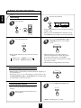
■ SUBWOOFER PRE OUT connection
PRE OUT
SUB
WOOFER
MANUFACTURED UNDER LICENSE FROM DIGITAL THEATER SYSTEMS,INC.
US PAT. NO. 5,451,942, 5,956,674, 5,974,380, 5,978,762 AND OTHER WORLD-WIDE
PATENTS ISSUED AND PENDING. "DTS" AND "DTS DIGITAL SURROUND" ARE
REGISTERED TRADEMARKS OF DIGITAL THEATER SYSTEMS, INC.
COPYRIGHT 1996, 2000 DIGITAL THEATER SYSTEMS, INC. ALL RIGHTS RESERVED.
AVIS : RISQUE DE CHOC ELECTRIQUE-NE PAS OUVRIR.
WARNING : SHOCK HAZARD-DO NOT OPEN.
WARNING : TO REDUCE THE RISK OF FIRE OR ELECTRIC SHOCK,
DO NOT EXPOSE THIS APPLIANCE TO RAIN OR MOISTURE.
Powered subwoofer
AM
LOOP
6-CH DIRECT INPUT
CENTER
SUB
WOOFER
SER. NO
AC INPUT
230V~50Hz
200W
MODEL NO. RD-6108R
AUDIO/VIDEO RECEIVER
DESIGNED IN USA
ASSEMBLED IN CHINA
DIGITAL IN
PRE OUT
OPTICAL
COAX 1
COAX 2
AC OUTLET
SUB
WOOFER
CD
FM
75Ω
TAPE MON.
VIDEO 1
VIDEO 2
VIDEO
IN
VIDEO
OUT
VIDEO 2
MONITOR
DIGI
-LINK
MANUFACTURED UNDER LICENSE FROM DOLBY
LABORATORIES. “DOLBY”, “PRO LOGIC”, AND
THE DOUBLE-D SYMBOL ARE TRADEMARKS OF
DOLBY LABORATORIES.
L
L
R
• To emphasize the deep bass sounds, connect a
powered subwoofer.
ANTENNA
R
FRONT
REAR
AUX
PLAY
REC
PLAY
REC
PLAY
VIDEO 1
VIDEO 1
SWITCHED
230V~50Hz
100W MAX
■ CONNECTING SPEAKERS
■ CONNECTING DIGITAL INPUTS
DIGITAL IN
Front left
Rear left
Front right
Rear right
Component with
COAXIAL DIGITAL OUT
OPTICAL
COAX 1
COAX 2
Component with
COAXIAL DIGITAL OUT
Component with
OPTICAL DIGITAL OUT
• The COAXIAL or the OPTICAL DIGITAL OUTs
of the components that are connected to CD and
VIDEO 1~3 of this unit can be connected to these
DIGITAL INPUTS.
• A digital input should be connected to the
components such as a CD player, LD player, DVD
player, etc. capable of outputting DTS Digital
Surround, Dolby Digital or PCM format digital
signals.
• For details, refer to the operating instructions of the
component connected.
• When making the COAXIAL DIGITAL
connection, be sure to use a 75Ω COAXIAL cord,
not a conventional AUDIO cord.
• All of the commercially available optical fiber cords
cannot be used for the equipment. If there is an
optical fiber cord which cannot be connected to your
equipment, consult your dealer or nearest service
organization.
L
R
Center
• Never short-circuit the + and - speaker cords.
• Be sure to connect speakers firmly and correctly according to the
channel (left and right) and the polarity (+ and -).
• Be sure to use the speakers with the impedance of over 6Ω.
• For installing the speakers, refer to "Speaker placement" on page
15.
6
■ AC INPUT CORD
MANUFACTURED UNDER LICENSE FROM DIGITAL THEATER SYSTEMS,INC.
US PAT. NO. 5,451,942, 5,956,674, 5,974,380, 5,978,762 AND OTHER WORLD-WIDE
PATENTS ISSUED AND PENDING. "DTS" AND "DTS DIGITAL SURROUND" ARE
REGISTERED TRADEMARKS OF DIGITAL THEATER SYSTEMS, INC.
COPYRIGHT 1996, 2000 DIGITAL THEATER SYSTEMS, INC. ALL RIGHTS RESERVED.
AVIS : RISQUE DE CHOC ELECTRIQUE-NE PAS OUVRIR.
WARNING : SHOCK HAZARD-DO NOT OPEN.
WARNING : TO REDUCE THE RISK OF FIRE OR ELECTRIC SHOCK,
DO NOT EXPOSE THIS APPLIANCE TO RAIN OR MOISTURE.
AM
LOOP
6-CH DIRECT INPUT
CENTER
SUB
WOOFER
ENGLISH
Plug this cord into a wall AC
outlet.
SER. NO
AC INPUT
230V~50Hz
200W
MODEL NO. RD-6108R
AUDIO/VIDEO RECEIVER
DESIGNED IN USA
ASSEMBLED IN CHINA
DIGITAL IN
PRE OUT
OPTICAL
COAX 1
COAX 2
AC OUTLET
SUB
WOOFER
CD
FM
75Ω
TAPE MON.
VIDEO 1
VIDEO 2
VIDEO
IN
VIDEO
OUT
VIDEO 2
MONITOR
DIGI
-LINK
MANUFACTURED UNDER LICENSE FROM DOLBY
LABORATORIES. “DOLBY”, “PRO LOGIC”, AND
THE DOUBLE-D SYMBOL ARE TRADEMARKS OF
DOLBY LABORATORIES.
L
L
R
ANTENNA
R
FRONT
REAR
AUX
PLAY
REC
PLAY
REC
PLAY
VIDEO 1
VIDEO 1
SWITCHED
230V~50Hz
100W MAX
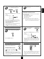
■ CONNECTING SYSTEM CONTROL
■ SWITCHED AC OUTLET
Sherwood component
with DIGI LINK II or III
• This outlet is switched on(power-on
mode) and off(standby mode) according
to power control as follows(Maximum
total capacity is 100W):
CD player
DIGI
-LINK
Tape deck
System
control
cord
Standby mode — switched AC outlet off
Power-on mode — switched AC outlet on
Graphic equalizer
DVD player
• Connect this jack to the DIGI LINK jack of the
external Sherwood component that uses the DIGI
LINK II or III remote control system.
7
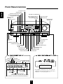
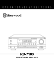
Front Panel Controls
ENGLISH
6 CH DIRECT BUTTON
REMOTE SENSOR
AUDIO INPUT SELECTOR BUTTON
TONE DIRECT BUTTON/INDICATOR
VIDEO INPUT SELECTOR BUTTON
TAPE MONITOR BUTTON
DIGITAL INPUT BUTTON
RDS BUTTONS(RD-6108R only)
Refer to "Additional Function for
RD-6108R RDS Tuner Only"
on page 22.
STANDBY BUTTON/
INDICATOR
POWER SWITCH
STEREO BUTTON
MASTER VOLUME
CONTROL KNOB
MASTER VOLUME
AUDIO/VIDEO RECEIVER RD-6108R
MAIN POWER
RDS EON TA TP PTY ST TUNED
REMOTE
SENSOR
TAPE
M
dB
kHz
MHz
DTS
ON/
DIGITAL
Pro Logic
THEATER
HALL
EON PTY
EON TA
DISPLAY
PTY SELECT
SEARCH
PRESET
MEM
TONE
DIRECT
ms
SLEEP
OFF
INPUT SELECTOR
STANDBY
VIDEO
AUDIO
SURROUND MODE
TAPE MON.
6CH DIRECT
AUTO
DSP MODE
STEREO
DIGITAL
INPUTS
TONE
DIRECT
ON/STANDBY
VIDEO 3
PHONES
CHANNEL
SELECTOR
SPEAKER
ADJUST
TONE MODE
SPEAKER
MODE
DYNAMIC
RANGE
CINEMA EQ
MEMO/ENTER
TUNING/PRESET
T/P MODE
FM MODE
BAND
ON/OFF
VIDEO
L - AUDIO - R
DSP MODE BUTTON
HEADPHONE
JACK
AUTO BUTTON
SPEAKER BUTTON/INDICATOR
BAND BUTTON
FM MODE BUTTON
CHANNEL SELECTOR BUTTON
TUNING/PRESET MODE BUTTON
ADJUST UP/DOWN
( / ) BUTTONS
TUNING/PRESET UP/DOWN
( / ) BUTTONS
TONE MODE BUTTON
SPEAKER MODE BUTTON
DYNAMIC RANGE BUTTON
MEMORY/ENTER BUTTON
CINEMA EQ BUTTON
TA INDICATOR
TP INDICATOR
EON INDICATOR
RDS
INDICATOR
PTY INDICATOR
VIDEO 3
STEREO INDICATOR
TAPE MONITOR INDICATOR
TUNED INDICATOR
MEMORY INDICATOR
VIDEO
RDS EON TP TA PTY ST TUNED
TAPE
M
dB
kHz
MHz
DTS
DIGITAL
Pro Logic
THEATER
HALL
PRESET
L - AUDIO - R
Additional video component
MEM
OUT
OUT
ms
SLEEP
• The VIDEO 3 jacks may be also connected to an
additional video component such as a camcorder, a
LD player or a video game player, etc.
THEATER INDICATOR
DTS INDICATOR
DOLBY( ) DIGITAL
HALL INDICATOR
INDICATOR
DOLBY( ) PRO LOGIC INDICATOR
PRESET NUMBER, SLEEP TIME, DELAY TIME DISPLAY
INPUT, FREQUENCY, VOLUME LEVEL, OPERATING INFORMATION, etc.
8
You can remotely control not only this receiver but also Sherwood compatible components bearing the DIGI LINK II or
III logo.
For system remote control operation, first make the DIGI LINK connections.
PRESET SCAN BUTTON
POWER BUTTON
■ CD PLAYER SECTION
DISC(CD changer only)-for disc selection
- to begin play.
- for pausing play.
,
- for skipping backward or forward.
- to stop play or to clear a program.
REPEAT A< >B - to play a specific passage
repeatedly.
INTRO SCAN - to preview each track only
for 10 sec.
POWER
NUMERIC(1~0) BUTTONS
P.SCAN
1
2
3
4
5
6
7
8
9
0
DISC
CD
REPEAT
INTRO
A< <B
■ TAPE DECK SECTION
DECK SELECTOR A, B - for selecting deck A or B
, - to begin reverse or forward side playback.
,
- to wind tape reverse or forward.
- for pausing playback or recording.
- to stop playback or recording.
- for recording.
A
■ EQUALIZER SECTION
DECK SEL.
B
DECK
PRESET
USER
FILE
T.MON
DISPLAY
CD
TUNER
VIDEO1
EQUALIZER
TAPE MON. VIDEO2
STEREO
INPUT SELECTOR BUTTONS
In the standby mode, when pressing an input
selector button, the unit is turned on automatically
and the desired input source is selected.
For selecting preset stations in tuner mode.
For selecting a track or a disc in CD mode.
When selecting a disc, select disc No.(1~5) within 2
sec. after pressing the DISC button.
AUX
6CH DIRECT
VIDEO3
AUTO
DSP MODE
PRESET - for selecting equalizer pattern.
USER - for adjusting equalizer pattern as desired.
FILE - for selecting desired equalizer pattern in the
preset or in the user mode.
T.MON - for monitoring the sound of recording or
playback on tape deck.
DISPLAY - for selecting equalizer display.
STEREO BUTTON
DSP MODE BUTTON
INPUT
SELECTOR
D.TIME
ADJUST
DISPLAY
SLEEP
CH LEVEL
DELAY ADJUST BUTTON
DISPLAY BUTTON
SLEEP BUTTON
CHANNEL LEVEL UP/DOWN
( / ) BUTTONS
AUTO BUTTON
CHANNEL SELECTOR BUTTON
CH SEL.
T.TONE
TEST TONE BUTTON
DELAY TIME BUTTON
MASTER
MUTE
MASTER VOLUME UP/DOWN
( / ) BUTTONS
SYS
MUTE BUTTON
In the DIGI LINK III remote control system, if pressing PLAY, etc. on CD player or tape deck, CD or TAPE MONITOR
is selected automatically without selecting the input source and then PLAY, etc. starts.
Notes:
Some functions for a CD player, tape deck or equalizer may not be available.
For details about functions, refer to the operating instructions of each component.
9
ENGLISH
DIGI LINK III System Remote Controls
ENGLISH
REMOTE CONTROL OPERATION RANGE
AUDIO/VIDEO RECEIVER RD-6108R
MASTER VOLUME
MAIN POWER
RDS EON TA TP PTY ST TUNED
REMOTE
SENSOR
TAPE
M
dB
kHz
MHz
DTS
ON/
DIGITAL
Pro Logic
THEATER
HALL
EON PTY
EON TA
DISPLAY
PTY SELECT
SEARCH
PRESET
MEM
ms
SLEEP
TONE
DIRECT
OFF
INPUT SELECTOR
STANDBY
VIDEO
AUDIO
TAPE MON.
SURROUND MODE
6CH DIRECT
AUTO
DSP MODE
STEREO
DIGITAL
INPUTS
TONE
DIRECT
ON/STANDBY
VIDEO 3
PHONES
SPEAKER
CHANNEL
SELECTOR
TONE MODE
ADJUST
SPEAKER
MODE
DYNAMIC
RANGE
CINEMA EQ
MEMO/ENTER
TUNING/PRESET
T/P MODE
FM MODE
BAND
ON/OFF
VIDEO
L - AUDIO - R
7m
30
30
POWER
P.SCAN
1
2
3
6
7
8
4
5
9
0
REPEAT
INTRO
DISC
CD
A< <B
A
DECK SEL.
B
DECK
PRESET
CD
AUX
USER
FILE
TUNER
VIDEO1
T.MON
6CH DIRECT
VIDEO3
DISPLAY
EQUALIZER
TAPE MON. VIDEO2
STEREO
AUTO
DSP MODE
INPUT
SELECTOR
CH SEL.
T.TONE
D.TIME
ADJUST
DISPLAY
SLEEP
CH LEVEL
MASTER
MUTE
Use the remote control unit within a range of about
7 meters (23 feet) and angles of up to 30 degrees
aiming at the remote sensor.
SYS
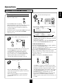
LOADING BATTERIES
1
Remove the cover.
2
Load two batteries matching the polarity.
("AAA" size)
Remove the batteries when they are not used for a
long time.
Do not use the rechargeable batteries(Ni-Cd type).
10
Operations
Before operation
Enter the standby mode.
3
MAIN POWER
ENGLISH
LISTENING TO A PROGRAM SOURCE
Select the desired input source.
POWER
INPUT SELECTOR
AUDIO
VIDEO
CD
TAPE MON.
TUNER
VIDEO1
P.SCAN
1
2
3
6
7
8
4
5
9
0
REPEAT
INTRO
DISC
CD
A< <B
ON/
OFF
A
DECK SEL.
B
AUX
TAPE MON. VIDEO2
DECK
PRESET
CD
USER
TUNER
AUX
or
FILE
VIDEO1
T.MON
VIDEO3
DISPLAY
EQUALIZER
TAPE MON. VIDEO2
6CH DIRECT
STEREO
AUTO
DSP MODE
INPUT
SELECTOR
VIDEO3
CH SEL.
T.TONE
D.TIME
ADJUST
CH LEVEL
DISPLAY
SLEEP
MASTER
MUTE
SYS
The STANDBY indicator lights up.
This means that the receiver is not disconnected from
the AC mains and a small amount of current is
retained to support the memorized contents and
operation readiness.
To switch the power off, push the POWER switch again.
Then the power is cut off and the STANDBY
indicator goes off.
1
In the standby mode, turn the power on.
POWER
POWER
P.SCAN
1
2
3
6
7
8
4
5
9
0
REPEAT
INTRO
CD
A< <B
A
DECK SEL.
B
DECK
PRESET
ON/STANDBY
CD
AUX
or
USER
FILE
TUNER
VIDEO1
T.MON
VIDEO3
DISPLAY
STEREO
AUTO
TAPE MONITOR function
You can connect either a tape deck or a graphic equalizer to
the receiver’s TAPE MONITOR jacks.
Only when you listen to the component connected to these
jacks, set the TAPE MONITOR button to on.
If you connect a 3-head tape deck, you can listen to the sound
being recorded during recording, not the source sound.
For further details, refer to the operating instructions of the
component connected.
When selecting the 6 CH DIRECT as desired,
DSP MODE
INPUT
SELECTOR
CH SEL.
T.TONE
D.TIME
ADJUST
DISPLAY
SLEEP
Each time the “VIDEO” button is pressed, the input
source changes as follows;
→ VIDEO 1 → VIDEO 2 → VIDEO 3
EQUALIZER
TAPE MON. VIDEO2
6CH DIRECT
(frequency display)
When the TAPE MONITOR button is set to on so that
“TAPE M” indicator lights up, other inputs can not be
heard from the speakers.
To listen to an input source other than TAPE MONITOR,
be sure to set the TAPE MONITOR button to off.
DISC
STANDBY
Each time the “AUDIO” button is pressed, the input
source changes as follows;
→ TUNER → CD → AUX
CH LEVEL
MASTER
MUTE
SYS
Each time the STANDBY button on the front panel
or the POWER button on the remote control is
pressed, the receiver is turned on to enter the
operating mode or off to enter the standby mode.
In the standby mode, if the INPUT SELECTOR
button is pressed, the receiver is turned on
automatically and the desired input is selected.
POWER
6CH DIRECT
P.SCAN
1
2
3
6
7
8
4
5
9
0
REPEAT
INTRO
DISC
CD
A< <B
A
DECK SEL.
B
PRESET
2
or
Switch the speakers on.
CD
AUX
DECK
USER
FILE
TUNER
VCR 1
T.MON
DISPLAY
EQUALIZER
TAPE MON. VCR 2
6CH DIRECT
STEREO
DVD/TV
DSP MODE
INPUT
SELECTOR
CH SEL.
T.TONE
6CH DIRECT
D.TIME
ADJUST
CH LEVEL
DISPLAY
SLEEP
MASTER
MUTE
SYS
SPEAKER
ON/OFF
“6-DIRECT” is displayed and the 6 separate analog
signals from 6 CH decoder connected to this unit pass
through the tone (bass, treble) and volume circuits
only and directly transfer to the speakers. (In case that
the TAPE MONITOR button is set to on, the TAPE
MONITOR button is automatically set to off.)
Press the 6 CH DIRECT button or select the desired
input source to cancel the 6 CH direct function.
These 6 separate analog signals can be heard only, not
recorded.
Then the SPEAKER indicator lights up and the
sound can be heard from the speakers connected to
the speaker terminals.
When using the headphone for private listening,
press the SPEAKER button again to switch the
speakers off.
11
ENGLISH
When CD, VIDEO 1~3 is selected as an
input source
4
7
To compensate for edgy or shrill movie
sound tracks.
Select the digital or analog input
connected as desired.
CINEMA EQ
DIGITAL
INPUTS
Then “C- EQ ON” is displayed.
Press it again to cancel, the “C- EQ OFF” is
displayed.
When the 6 CH DIRECT is selected as an input
source, the cinema EQ function does not work.
Each time this button is pressed, the corresponding
input is selected as follows ;
o(ptical) 1
c(oaxial) 1
c(oaxial) 2
A(nalog)
To listen to a DTS or Dolby Digital program source
in the 2-CH downmix mode, in the stereo mode, the
corresponding digital input should be selected. (For
details, refer to “Downmixing into 2 front channels”
on page 19.)
8
To mute the sound.
POWER
P.SCAN
1
2
3
6
7
8
4
5
9
0
REPEAT
INTRO
DISC
CD
A< <B
Notes :
When the selected optical or coaxial digital input is
not connected, the selected digital input display is
flickering, meaning no sound. (Refer to
“ENJOYING SURROUND SOUND” on page 16.)
The sound from the component connected to the
selected digital input can be heard regardless of the
selected input source.
5
A
DECK SEL.
B
DECK
PRESET
CD
USER
TUNER
AUX
FILE
VIDEO1
T.MON
VIDEO3
DISPLAY
EQUALIZER
TAPE MON. VIDEO2
6CH DIRECT
STEREO
AUTO
DSP MODE
INPUT
SELECTOR
CH SEL.
T.TONE
D.TIME
ADJUST
DISPLAY
SLEEP
CH LEVEL
MASTER
MUTE
MUTE
SYS
“MUTE” will flicker.
To resume the previous sound level, press it again.
Operate the selected component for
playback.
9
To listen with the headphones.
PHONES
When playing back the program sources with
surround sound, refer to “ENJOYING SURROUND
SOUND” on page 16.
6
Adjust the (overall) volume.
POWER
MASTER VOLUME
Ensure that the SPEAKER button is set to off.
When listening to a DTS or Dolby Digital program
source, if the headphones are plugged in and the
SPEAKER button is set to off, it enters the 2-CH
downmix mode automatically. (For details, refer to
“Downmixing into 2 front channels”on page 19.)
P.SCAN
1
2
3
6
7
8
4
5
9
0
REPEAT
INTRO
DISC
CD
A< <B
A
DECK SEL.
B
DECK
PRESET
CD
or
USER
TUNER
AUX
FILE
VIDEO1
T.MON
VIDEO3
STEREO
AUTO
CH SEL.
T.TONE
DISPLAY
MASTER
ADJUST
CH LEVEL
UP
DSP MODE
INPUT
SELECTOR
D.TIME
DOWN
DISPLAY
EQUALIZER
TAPE MON. VIDEO2
6CH DIRECT
SLEEP
MASTER
MUTE
SYS
12
10
11
Enter the tone mode.
At the desired tone mode, adjust the tone
as desired.
ADJUST
TONE MODE
If the tone display disappears, start from the step 10
again.
Notes:
Extreme settings at high volume may damage your
speakers.
When the digital signals from DTS or Dolby
Digital program sources are input in available
surround mode, the tone cannot be adjusted and the
tone direct function is automatically switched to
ON.
Each time this button is pressed, the corresponding
tone mode is selected and shown for 3 seconds as
follows:
BASS TRBL(treble)
Note: When the TONE DIRECT indicator is
lighting up, the tone mode cannot be
entered.
12
To listen to a program source without the
tone effect.
TONE
DIRECT
The TONE DIRECT indicator lights up and the
sound that bypasses the tone circuitry will be
heard.
To cancel the tone direct function, press this
button again.
13
ENGLISH
Adjusting the tone(bass and treble)
ENGLISH
SURROUND SOUND
This receiver incorporates a sophisticated Digital Signal Processor that allows you to create optimum sound
quality and sound atmosphere in your personal Home Theater.
Surround modes
DTS Digital Surround
DTS Digital Surround(also called simply DTS) is a multichannel digital signal format which can handle more
amount of data than Dolby Digital, providing better audio
quality. Though the number of audio channels is 5.1(front
left, front right, center, rear(surround) left, rear(surround)
right and Low Frequency Effects) which is same as Dolby
Digital, discs bearing the “
” provides fat sound
Dolby Pro Logic
Dolby Pro Logic is a specially encoded two channel
surround format which consists of four channels (front
left, center, front right and surround). Sources bearing the
“
DOLBY SURROUND ” provide the theater-like surround
sound.
The surround channel is monaural, but is played through
two surround speakers.
and better signal - to - noise ratio, thanks to the lower audio
compression ratio format.
It also provides wide dynamic range and better separation,
resulting in magnificent sound.
“DTS” and “DTS Digital Surround” are registered
trademarks of Digital Theater Systems,Inc.
Dolby Virtual
This mode employs sophisticated digital processing to
create the illusion of “phantom” speakers, this mode
allows you to experience surround sound effects from the
Dolby Digital, Dolby Surround or 2-channel(recorded in
digital PCM or analog stereo) sources, through just a
single pair of front speakers.
Dolby Digital
Dolby Digital is the multi-channel digital signal format
developed by Dolby Laboratories. Discs bearing the
“
DOLBY ” includes the recording of up to 5. 1 channels
Manufactured under license from Dolby Laboratories.
“Dolby”, “Pro Logic”, and the double-D symbol are
trademarks of Dolby Laboratories.
D I G I T A L
of digital signals, which can reproduce much better sound
quality, spatial expansion and dynamic range characteristics
than the previous Dolby Surround effect.
Dolby Pro Logic II surround
This mode applies conventional 2- channel signals such as
digital PCM or analog stereo signals as well as Dolby
Surround signals, etc. to surround processing to offer
improvements over conventional Dolby Pro Logic circuits.
Dolby Pro Logic ll surround includes 4 modes as follows:
• Dolby Pro Logic ll MOVIE
When enjoying movies, this mode allows you to further
enhance the cinematic quality by adding processing that
emphasizes the sounds of the action special effects.
• Dolby Pro Logic ll MUSIC
When listening to music, this mode allows you to further
enhance the sound quality by adding processing that
emphasizes the musical effects.
• Dolby Pro Logic ll MATRIX
When listening to poor FM broadcasts, this mode allows
you to further enhance the sound quality by the ultimate
cure for poor FM stereo signals.
• Dolby Pro Logic ll CUSTOM
This mode reproduces a delayed signals from the surround
channels to emphasize the sense of expansion.
• The following modes apply conventional 2-channel
signals such as digital PCM or analog stereo signals to
high performance Digital Processor to recreate sound
fields artificially.
THEATER
This mode provides the effect of being in a movie theater
when watching a movie source.
HALL
This mode provides the ambience of a concert hall for
classical music sources such as orchestral, chamber music,
or an instrumental solo.
STADIUM
This mode provides the expansive sound field to achieve
the true stadium effect when watching baseball or soccer
games.
CHURCH
This mode provides the ambience of a church for baroque,
string orchestral or choral group music.
• When the 6 CH DIRECT INPUTs are connected to the 6 CH decoder for a surround sound such as Dolby Digital or
DTS, etc., you can enjoy the corresponding surround sound, too. (For details, see the operator’s manual of the
component to be connected.)
14
When the center speaker or the rear speakers is(are) closer to the listener than the front speakers, the sound from
the center speaker or the rear speakers can arrive at the listener’s ears earlier than the sound from the front
speakers.
In this case, the imaging is not as sharp and stable as it could be.
For audible improvement, the sound from center speaker can be delayed with the center delay time setting so that
the sound from the front and the center speakers will be heard at the same time and the sound from the rear
speakers can be also delayed with the rear delay time setting so that the sound from the front and the rear speakers
will be heard at the same time.
The optimum delay time will be different according to the room size and the acoustic properties. It is
recommended that you try several times to obtain the best effect.
It is adjustable in Dolby Digital, Dolby Pro Logic II, Dolby Pro Logic or Dolby Virtual modes. (For details,
refer to “In Dolby Digital, Dolby Pro Logic II, Dolby Pro Logic or Dolby Virtual mode, adjusting delay times of
the speakers” on page 19)
Speaker placement
To obtain the best surround sound effect in your home, place the speakers as
follows;
Front speakers: Place each front speaker about 1m (40″) from the TV set.
Center speaker: Place the center speaker either above or below the TV set to
assure good visualization of center channel program.
Rear speakers: Place the rear speakers approximately 1m above the ear level
of a seated listener on the direct left and right of them or
slightly behind.
Subwoofer: Reproduces powerful deep bass sounds. Place a powered
subwoofer anywhere in the front as desired.
The ideal surround system needs all the speakers listed above.
To obtain the best surround effects, the speakers except the subwoofer should
be full range speakers.
Note: To avoid interference with the TV picture, use only magnetically
shielded center and front speakers.
For your reference, the sound from each channel can be reproduced according
to the surround modes as follows:
Modes DTS
TV set
FRONT
LEFT
FRONT
RIGHT
CENTER
SPEAKER
SUB
WOOFER
REAR
LEFT
REAR
RIGHT
Dolby Digital
Dolby Pro Logic II
Dolby Pro Logic
Dolby Virtual
Other Surround
Stereo
6 CH DIRECT
Front L/R
○
○
○
○
○
○
○
○
Center
○
○
○
○
-
○
-
○
Rear L/R
○
○
○
○
-
○
-
○
Subwoofer
○
○
○
○
○
○
○
○
Channels
• Depending on the speaker settings, the sound from the corresponding channels cannot be reproduced.
(For details, refer to “Adjusting the speaker settings” on page 17.)
15
ENGLISH
Delay time
ENGLISH
ENJOYING SURROUND SOUND
Surround sound effect will not work properly if the signal passes through a graphic equalizer.
Please refer to your equalizer operating instructions for guidance on switching off (or defeating) the equalizer.
1
Depending on the input digital signal format, select the
desired decoding mode.
When canceling the surround mode for stereo operation.
POWER
POWER
AUTO
P.SCAN
1
2
3
4
6
7
8
9
STEREO
5
P.SCAN
1
2
3
6
7
8
4
5
9
0
REPEAT
INTRO
0
DISC
CD
DISC
CD
REPEAT
A< <B
INTRO
A< <B
A
DECK SEL.
A
B
DECK SEL.
B
PRESET
CD
or
AUX
USER
FILE
TUNER
VIDEO1
T.MON
VIDEO3
DISPLAY
or
EQUALIZER
TAPE MON. VIDEO2
6CH DIRECT
STEREO
AUTO
DECK
PRESET
DECK
AUTO
DSP MODE
INPUT
SELECTOR
CD
USER
TUNER
AUX
FILE
VIDEO1
T.MON
EQUALIZER
TAPE MON. VIDEO2
6CH DIRECT
VIDEO3
DISPLAY
STEREO
AUTO
DSP MODE
STEREO
INPUT
SELECTOR
CH SEL.
T.TONE
CH SEL.
T.TONE
D.TIME
ADJUST
CH LEVEL
D.TIME
ADJUST
DISPLAY
SLEEP
CH LEVEL
DISPLAY
MASTER
SLEEP
MASTER
MUTE
SYS
MUTE
SYS
• Each time the AUTO button is pressed, the decoding mode changes as
follows:
• Then the stereo mode is selected.
• To cancel the stereo mode, select the desired surround mode with
using the DSP MODE button.
IN-AUTO : The input digital signal format(DTS, Dolby Digital or
PCM(2 channel stereo), etc.) used by the selected digital input
source is detected automatically to perform the necessary
decoding process for optimum surround modes.
IN-DTS : The DTS signal processing is performed only when DTS
signals are input.
IN-PCM : The PCM signal processing is performed only when PCM
signals are input.
Notes:
• Only when the digital input is selected as signal input for the input
sources except TUNER, AUX and TAPE MONITOR, the decoding
mode can be selected.
• Noise may be generated at the beginning of playback and while
searching during DTS playback in the IN-AUTO mode. In this case,
try playing in the IN-DTS mode.
Adjusting the Dolby Pro Logic II parameters
• When selecting the Dolby Pro Logic II Music and Custom modes,
you can adjust the various surround parameters for optimum
surround effect.
3
While scrolling “PL II MUSIC”(for Dolby Pro Logic II
Music mode) or “PL II CUSTOM”(for Dolby Pro
Logic II Custom mode), press the MEMORY/ENTER
button to select the desired parameter.
MEMO/ENTER
Select the desired surround mode.
2
POWER
DSP MODE
P.SCAN
1
2
3
6
7
8
4
5
9
0
REPEAT
INTRO
DISC
CD
A< <B
A
DECK SEL.
B
DECK
PRESET
CD
or
AUX
USER
FILE
TUNER
VIDEO1
T.MON
VIDEO3
DISPLAY
EQUALIZER
TAPE MON. VIDEO2
6CH DIRECT
• Each time this button is pressed, the parameter changes and is
displayed for 5 seconds as follows:
※ Panorama mode(“PANO”) : This mode extends the front stereo image
to include the surround speakers for an exciting “wraparound”effect
with side wall imaging. Select “OFF” or “ON”.
※ Center width control(“C-WID”) : This control adjusts the center image
so it may be heard only from the center speaker, only from the
left/right speakers as a phantom image, or from all three front speakers
to varying degrees. The control can be set in 8 steps from 0 to 7.
※ Dimension control(“DIMEN”) : This control gradually adjusts the
soundfield either towards the front or towards the rear. The control can
be set in 7 steps from - 4 to +2.
※ 7 kHz Low Pass Filter(“ LPF”) : Select “OFF” or “ON” to turn off or
on the pass filter on the surround channels.
※ Shelf Filter(“SH - F”) : Select “OFF” or “ON” to turn off or on the
shelf filter on the surround channels.
※ Right Surround Channel Polarity Inversion(“PO - I”) : Select “OFF” or
“ON” to turn off or on the polarity inversion.
※ Automatic Balancing(“BAL”) : Select “ OFF” or “ON” to turn off or
on the automatic balancing
• If the Dolby Pro Logic II Music or Custom display disappears, you
cannot select the parameter. In this case, select the desired surround
mode again by pressing the DSP MODE button.
• In the Dolby Pro Logic II Music mode, you cannot select the 7 kHz Low
Pass Filter, Shelf Filter, Right Surround Channel Polarity Inversion and
Automatic Balancing.
• For your reference, the initial settings for parameters are as follows:
“PANO” : “OFF”, “C-WID” : “0”, “DIMEN” : “0”, “LPF” : “OFF”,
“SH-F” : “OFF”, “PO-I” : “ON”, “BAL” : “OFF”.
STEREO
AUTO
DSP MODE
DSP MODE
INPUT
SELECTOR
CH SEL.
T.TONE
D.TIME
ADJUST
DISPLAY
SLEEP
CH LEVEL
MASTER
MUTE
SYS
• Each time the DSP MODE button is pressed, the surround mode changes
depending on the input signal format and the selected decoding mode as
follows:
※ When Dolby Digital signals are input in the IN-AUTO mode, one of the
following modes can be selected depending on the number of the recorded
channels.
• Dolby Digital 5.1-channel sources: DOLBY DIGITAL and DOLBY VIRTUAL.
• Dolby Digital 2-channel sources: DOLBY PRO LOGIC II MOVIE, DOLBY PRO
LOGIC, DOLBY PRO LOGIC II MUSIC, DOLBY PRO LOGIC II MATRIX,
DOLBY PRO LOGIC II CUSTOM and DOLBY VIRTUAL.
※ When PCM(2 channel stereo) signals are input in the IN-AUTO or IN-PCM
mode, one of the following modes can be selected :
DOLBY PRO LOGIC II MOVIE, DOLBY PRO LOGIC, DOLBY PRO LOGIC II MUSIC,
DOLBY PRO LOGIC II MATRIX, DOLBY PRO LOGIC II CUSTOM, DOLBY VIRTUAL,
CHURCH, THEATER,HALL and STADIUM.
• When the analog input is selected as signal input and analog stereo signals
are input, you can select the desired of these above surround modes, too.
• However, when DTS signals are input in the IN-AUTO or IN-DTS mode,
the DTS mode will be selected regardless of using the DSP MODE button.
Notes:
• When the selected decoding mode is not matched to the input signal format,
no sound is heard. Therefore, be sure to select the required decoding mode
and the available surround mode according to the input signal format.
• When the 6 CH DIRECT is selected as an input source, the decoding and
surround modes cannot be selected.
16
ADJUST
5
Note:
In the Dolby Pro Logic II Customer mode, you cannot set both of
the 7 kHz Low Pass Filter and Shelf Filter to ON simultaneously.
If so, the filter set previously is automatically changed to OFF.
If the parameter display disappears, start from the
step 3 again.
Adjusting the speaker settings
7
Adjust the settings of front, center ,rear speakers and
subwoofer connected.
If the speaker setting is adjusted to “S”, the low range
bass sound of the channel(s) is redirected to the
subwoofer or the front channels and if the speaker
setting is adjusted to “N”, the sound of the channel(s)
is redirected to other channels.
6
Press the SPEAKER
MODE button for more
than 2 seconds to enter the
front-center-rear speaker
mode.
8
Select the desired speaker
setting.
ADJUST
Each time this button is pressed, one of 11 different
speaker settings is selected and displayed for 8
seconds as follows;
FL-CS-RS, FL-CL-RS, FL-CL-RL,
FL-CL-RN, FL-CS-RL, FL-CN-RL,
FL-CS-RN, FL-CN-RS, FS-CS-RS,
FS-CS-RN and FS-CN-RS
SPEAKER
MODE
In the displays, F stands for Front, C for Center, R
for Rear, L for Large, S for Small and N for None.
When judging whether a speaker is Large or Small,
please note that a standard large speaker can fully
reproduce sounds below 80 Hz.
The following speaker settings cannot be selected.
Front :Small, Center : Large and Rear : Large(FSCL-RL) or Center : None and Rear : None(CN-RN)
setting.
The front-center-rear speaker setting is displayed.
When the SPEAKER button is set to off or the 6 CH
DIRECT is selected as an input source, the speaker
mode function cannot be available.
When it is in the stereo or Dolby Virtual mode, only
the subwoofer setting can be adjusted.
Memorize the desired
speaker setting
while it is displayed.
Repeat the above steps 3 and 4 to adjust
other parameters.
MEMO/ENTER
9
Select the desired
subwoofer setting.
ADJUST
Each time this button is pressed, the subwoofer setting
changes and is displayed for 8 seconds as follows;
The desired speaker setting is memorized and then
it enters the subwoofer mode.
If the speaker setting display disappears, start from
the above step 6 again.
↓
SUB W(oofer) - Y(es): When using a subwoofer.
↓
SUB W(oofer) - N(o) : When not using a subwoofer.
In case that the front speaker is set to “S”, the
subwoofer is automatically set to “Y”.
10
Memorize the subwoofer
setting while it is
displayed.
Checking the speaker setting
MEMO/ENTER
SPEAKER
MODE
If the subwoofer setting display disappears, start
from the above step 6 again.
Each time this button is pressed briefly, the frontcenter-rear speaker or subwoofer setting is displayed.
17
ENGLISH
4
At the desired parameter,
adjust it as desired.
ENGLISH
Adjusting each channel level
11
12
Select the desired channel.
Adjust the level of the selected channel
as desired.
POWER
POWER
P.SCAN
1
2
3
6
7
8
4
5
9
0
REPEAT
INTRO
DISC
P.SCAN
CD
1
2
3
4
5
6
7
8
9
0
ADJUST
A< <B
A
CHANNEL
SELECTOR
DISC
DECK SEL.
CD
REPEAT
B
INTRO
DECK
PRESET
A< <B
USER
CD
TUNER
FILE
VIDEO1
T.MON
DISPLAY
EQUALIZER
A
DECK SEL.
AUX
B
or
TAPE MON. VIDEO2
STEREO
DECK
PRESET
USER
FILE
CD
TUNER
VIDEO1
AUX
T.MON
TAPE MON. VIDEO2
6CH DIRECT
or
DISPLAY
EQUALIZER
STEREO
VIDEO3
AUTO
DSP MODE
INPUT
SELECTOR
6CH DIRECT
VIDEO3
AUTO
DSP MODE
INPUT
SELECTOR
CH SEL.
T.TONE
CH LEVEL
CH SEL.
D.TIME
ADJUST
DISPLAY
SLEEP
CH LEVEL
MASTER
MUTE
SYS
CH SEL.
T.TONE
D.TIME
ADJUST
DISPLAY
SLEEP
CH LEVEL
MASTER
MUTE
SYS
The LFE level can be adjusted within the range of
-10~0 dB and other channel levels within the range
of -15~+15 dB.
In general, we recommend the LFE level to be
adjusted to 0 dB. (However, the recommend LFE
level for some early DTS software is -10 dB.) If the
recommended levels seems too high, lower the
setting as necessary.
If the channel display disappears, start from the
above step 11 again.
Each time this button is pressed, the corresponding
channel is selected and displayed for 3 seconds as
follows;
Front Left Center Front Right Rear Right
(Dolby Digital or DTS L(FE) )SubWoofer Rear Left
( ): Adjustable only when the digital signals from Dolby Digital or
DTS program source that includes LFE signal are input in the
available surround mode.
When it is in the stereo or Dolby Virtual mode, or
the speaker setting is “N”, center, rear or subwoofer
channel will not be selected.
13
Adjusting each channel level with
test tone
15
Only when it is in available surround modes except
the Dolby Virtual and stereo modes, the volume
level of each channel can be adjusted easily with the
test tone function.
Note: When the 6 CH DIRECT is selected as an input
source, the test tone function does not work.
14
Repeat the above steps 11 and 12 to
adjust other channel levels.
At each channel, adjust the level as desired
until the sound level of each speaker is
heard to be equally loud.
POWER
P.SCAN
1
2
3
6
7
8
4
5
9
0
REPEAT
INTRO
DISC
CD
ADJUST
A< <B
A
DECK SEL.
B
DECK
PRESET
CD
or
USER
TUNER
AUX
FILE
VIDEO1
T.MON
VIDEO3
DISPLAY
EQUALIZER
TAPE MON. VIDEO2
6CH DIRECT
STEREO
AUTO
DSP MODE
INPUT
SELECTOR
CH SEL.
T.TONE
CH LEVEL
D.TIME
ADJUST
CH LEVEL
DISPLAY
SLEEP
MASTER
MUTE
SYS
Enter the test tone mode.
POWER
P.SCAN
1
2
3
6
7
8
4
5
9
0
REPEAT
INTRO
You can select the desired channel and adjust its
level with repeating the steps 11 and 12 in
“Adjusting each channel level” procedure.
DISC
CD
A< <B
A
DECK SEL.
B
DECK
PRESET
CD
T.TONE
USER
TUNER
AUX
FILE
VIDEO1
T.MON
EQUALIZER
TAPE MON. VIDEO2
6CH DIRECT
VIDEO3
DISPLAY
STEREO
AUTO
DSP MODE
INPUT
SELECTOR
CH SEL.
T.TONE
D.TIME
ADJUST
CH LEVEL
DISPLAY
SLEEP
MASTER
MUTE
SYS
16
The test tone will be heard from the speaker of each
channel for 2 seconds as follows;
Front Left
Center
Front Right
SUBwoofer
Rear Left Rear Right
Cancel the test tone function.
POWER
P.SCAN
1
2
3
6
7
8
4
5
9
0
REPEAT
INTRO
DISC
CD
A< <B
A
DECK SEL.
B
DECK
PRESET
CD
T.TONE
USER
TUNER
AUX
When the speaker setting is “N”, the test tone of the
corresponding channel is not available.
When the selected decoding mode is not matched to
the input signal format, the test tone function cannot
work.
FILE
VIDEO1
T.MON
VIDEO3
DISPLAY
EQUALIZER
TAPE MON. VIDEO2
6CH DIRECT
STEREO
AUTO
DSP MODE
INPUT
SELECTOR
CH SEL.
T.TONE
D.TIME
ADJUST
CH LEVEL
DISPLAY
SYS
18
SLEEP
MASTER
MUTE
18
Adjust the delay time.
POWER
In case of Dolby Digital, Dolby Pro Logic II or Dolby
Pro Logic mode, when the distances from the prime
listening position to front left, center, front right, rear
left and rear right speakers are same, the basic settings
are as follows according to the surround modes;
17
3
7
8
4
5
9
0
REPEAT
INTRO
CD
A
DECK SEL.
B
DECK
PRESET
CD
AUX
ADJUST
USER
FILE
TUNER
VIDEO1
T.MON
VIDEO3
DISPLAY
EQUALIZER
TAPE MON. VIDEO2
6CH DIRECT
STEREO
AUTO
DSP MODE
INPUT
SELECTOR
CH SEL.
T.TONE
D.TIME
ADJUST
DISPLAY
SLEEP
CH LEVEL
MASTER
MUTE
SYS
Each time this button is pressed in the Dolby
Digital, Dolby Pro Logic II or Dolby Pro Logic
mode, the delay time changes in regular intervals.
Each time this button is pressed in the Dolby Virtual
mode, the delay mode changes as follows:
If the center or the rear speaker(s) is(are) not at the
same distance from the prime listening position as the
front speakers, increase or decrease the center delay
time by 1 ms for every about 30 cm(1 foot) it is closer
or farther away and increase or decrease the rear delay
time by 5 ms for every about 1~1.5 m(3~5 feet) it is
closer or farther away.
POWER
2
6
A< <B
- In the Dolby Digital mode,
Center delay time : 0 ms, Rear delay time : 0 ms
- In the Dolby Pro Logic II Music, Matrix or Custom mode,
Rear delay time : 0 ms
- In the Dolby Pro Logic II Movie, Dolby Pro Logic mode,
Rear delay time : 10 ms
Check the delay time
to be adjusted.
P.SCAN
1
DISC
NARROW: Relatively long distance from the
prime listening position to front
speakers.
WIDE: Relatively short distance.
P.SCAN
1
2
3
6
7
8
4
5
9
0
REPEAT
INTRO
DISC
CD
A< <B
If the delay time disappears, start from the step 17
again.
A
DECK SEL.
B
DECK
PRESET
CD
D.TIME
AUX
USER
FILE
TUNER
VIDEO1
T.MON
VIDEO3
DISPLAY
EQUALIZER
TAPE MON. VIDEO2
6CH DIRECT
STEREO
AUTO
DSP MODE
INPUT
SELECTOR
CH SEL.
T.TONE
D.TIME
ADJUST
DISPLAY
SLEEP
CH LEVEL
MASTER
MUTE
SYS
The delay time will be displayed for 5 seconds.
The corresponding delay time is displayed. The
center delay time can be adjusted in the Dolby
Digital mode only.
In the Dolby Virtual mode, “NARROW” or
“WIDE” is displayed.
19
In Dolby Digital mode, repeat the above
steps 17 and 18 to adjust the rear delay
time.
Downmixing into 2 front channels
Allows the multi-channel DTS or Dolby Digital signals
to be reproduced through only two speakers or through
headphones.
When the digital signals from the DTS or Dolby Digital
program sources are input in available surround mode,
press the STEREO button.
POWER
STEREO
P.SCAN
1
2
3
6
7
8
4
5
9
0
REPEAT
INTRO
DISC
CD
A< <B
A
DECK SEL.
B
DECK
PRESET
or
CD
USER
TUNER
AUX
FILE
VIDEO1
T.MON
VIDEO3
DISPLAY
EQUALIZER
TAPE MON. VIDEO2
6CH DIRECT
STEREO
AUTO
DSP MODE
STEREO
INPUT
SELECTOR
CH SEL.
T.TONE
D.TIME
ADJUST
DISPLAY
SLEEP
CH LEVEL
MASTER
MUTE
SYS
“ST” and the DTS or Dolby Digital indicators light up,
meaning it enters the 2-CH downmix mode, and then
the discrete multi-channels(except LFE) are mixed
down into 2 front channels.
19
To cancel the 2-CH downmix mode, select the
desired surround mode with using the DSP MODE
button.
When the playback of the source on the player is
stopped or interrupted, etc., the 2-CH downmix
mode is not canceled even though “ST” and the
DTS or Dolby Digital indicators go off.
If the headphones are plugged and the SPEAKER
button is set to off while the digital signals from the
DTS and Dolby Digital program sources are being
input, it will enter the 2-CH downmix mode
automatically(but only the DTS or Dolby Digital
indicator lights up still) and if the headphones are
unplugged and the SPEAKER button is set to on in
the 2-CH downmix mode, it will return to the
previous mode.
ENGLISH
In Dolby Digital, Dolby Pro Logic II, Dolby
Pro Logic or Dolby Virtual mode, adjusting
delay times of the speakers
ENGLISH
LISTENING TO RADIO BROADCASTS
Auto tuning
1
2
Select the tuner.
Select the desired band.
BAND
MHz
POWER
AUDIO
P.SCAN
1
2
3
4
6
7
8
9
5
0
DISC
CD
REPEAT
INTRO
A< <B
BAND
A
DECK SEL.
B
or
TUNER
DECK
PRESET
USER
FILE
CD
TUNER
VIDEO1
EQUALIZER
TAPE MON. VIDEO2
STEREO
AUX
6CH DIRECT
VIDEO3
T.MON
AUTO
Each time this button is pressed, the band is changed
to FM or AM.
When pressing the BAND button without selecting
the TUNER, the tuner will be selected automatically.
DSP MODE
INPUT
SELECTOR
CH SEL.
T.TONE
D.TIME
ADJUST
DISPLAY
SLEEP
CH LEVEL
MASTER
MUTE
SYS
3
FREQUENCY
DISPLAY
Select the tuning mode.
4
Press the TUNING/PRESET UP(▲) or
DOWN(▼) button for more than 0.5
second.
T/P MODE
TUNING/PRESET
Each time this button is pressed, the mode changes
as follows;
The tuner will now search until a station of
sufficient strength has been found. The display
shows the tuned frequency and “TUNED”.
If the station found is not the desired one, simply
repeat this operation.
Weak stations are skipped during auto tuning.
Tuning mode : “PRESET” goes off.
Preset mode : “PRESET” lights up.
Manual tuning
Manual tuning is useful when you already know the frequency of
the desired station.
Perform the steps 1 to 3 in “Auto tuning” procedure and press the
TUNING/PRESET UP(▲) or DOWN(▼) button repeatedly until
the right frequency has been reached.
Presetting radio stations
2
You can store up to 30 preferred stations in the
memory.
1
TUNING/PRESET
Press the MEMORY/ENTER button.
MEMO/ENTER
Tune in the desired station with auto or
manual tuning.
“MEM” is flickering for 5 seconds.
20
4
MEMO/ENTER
TUNING/PRESET
Repeat the above steps 1 to 3 to memorize
other stations.
ENGLISH
3
Select the desired preset number (1~30) and
press the MEMORY/ENTER button.
MEMORY BACKUP FUNCTION
When using the NUMERIC buttons on the remote
control.
Examples) For “3” :
The following items, set before the receiver is turned
off, are memorized.
INPUT SELECTOR settings
Surround mode settings
Preset stations,etc.
3
1
For “15” :
within 2 seconds
5
0
For “30” :
Note : If the electricity fails or the AC input cord is
disconnected for more than 2 weeks, they are all
cleared. So you should memorize them again.
The station has now been stored in the memory.
When using the NUMERIC buttons, the station is
stored automatically without pressing the
MEMORY/ENTER button.
A stored frequency is erased from the memory by
storing another frequency in its place.
If “MEM” goes off, start again from the above step 2.
Tuning to preset stations
1
2
After selecting the tuner as an input
source, select the preset tuning mode.
TUNING/PRESET
Select the desired
preset number.
When using the NUMERIC buttons on the remote
control.
Examples) For “3”:
T/P MODE
3
1
within 2 seconds
5
For “15”:
3
0
Then “PRESET” lights up.
0
)
When selecting the desired preset number with the
NUMERIC buttons, the desired preset station will be
tuned to automatically without selecting the preset
tuning mode.
Listening to FM stereo broadcasts
While listening to FM broadcasts.
within 2 seconds
(or
For “30”:
Scanning preset stations in sequence
FM MODE
POWER
P.SCAN
1
2
3
6
7
8
4
5
9
0
REPEAT
INTRO
P.SCAN
DISC
CD
A< <B
A
Each time this button is pressed,
the FM mode changes as follows;
DECK SEL.
B
DECK
PRESET
CD
USER
TUNER
AUX
FILE
VIDEO1
T.MON
VIDEO3
DISPLAY
EQUALIZER
TAPE MON. VIDEO2
6CH DIRECT
STEREO
AUTO
DSP MODE
INPUT
SELECTOR
CH SEL.
T.TONE
D.TIME
ADJUST
DISPLAY
SLEEP
CH LEVEL
Stereo mode : “ST” lights up.
Mono mode : “ST” goes off.
MASTER
MUTE
SYS
The receiver will start scanning the stations in the preset
sequence and each station is received for 5 seconds.
At the desired station, press this button again to stop
scanning.
When FM stereo broadcasts are poor because of
weak broadcast signals, select the FM mono mode to
reduce the noise, then FM broadcasts are reproduced
in monaural sound.
21
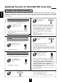
Additional Function for RD-6108R RDS Tuner Only
ENGLISH
LISTENING TO RDS BROADCASTS(FM only)
RDS(Radio Data System) is a method for sending information signals together with the transmitter signals. Your tuner is
capable of translating these signals and putting the information on the display. These codes contain the following
informations. Program Service name(PS), A list of Program Types(PTY), Traffic Announcement(TA), Clock Time(CT),
Radio Text(RT).
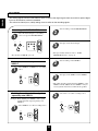
RDS search
2
Use this function to automatically search and
receive the stations offering RDS services.
1
In the FM mode, select
the RDS search mode.
TP search
2
Use this function to automatically search and receive
the stations broadcasting the traffic program.
1
PTY search
2
Use this function to automatically search and receive
the stations broadcasting the desired program type.
1
While displaying “TP
SRCH”.
TUNING/PRESET
The tuner automatically searches for stations
broadcasting the traffic program.
“NO TRAFF”is displayed if the signal is too weak or
there are no stations broadcasting the traffic program.
When “TP SRCH” is not displayed, repeat again from
the above step 1.
SEARCH
“TP SRCH” is displayed.
In the FM mode,
select the PTY search
mode.
TUNING/PRESET
The tuner automatically searches stations offering
RDS services and the station name is displayed.
If the station found is not the desired one, press the
TUNING/PRESET UP(▲) or DOWN(▼) button
again while the RDS indicator is flickering.
If no other RDS station is found, “NO RDS” is
displayed.
When “RDS SRCH” is not displayed, repeat again
from the above step 1.
SEARCH
Each time this button is pressed, the search mode
changes as follows;
RDS SRCH TP SRCH PTY SRCH OFF
In the FM mode, select
the TP search mode.
While displaying
“RDS SRCH”
While displaying “PTY
SRCH”, select the
desired program type.
PTY SELECT
Each time this button is pressed, one of 32 different
types of programs is selected.(NEWS, AFFAIRS, INFO,
SEARCH
SPORT, EDUCATE, DRAMA, CULTURE, SCIENCE,
VARIED, POP M, ROCK M, EASY M, LIGHT M, CLASSICS,
OTHER M, WEATHER, FINANCE, CHILDREN, SOCIAL,
RELIGION, PHONE IN, TRAVEL, LEISURE, JAZZ,
COUNTRY, NATION M, OLDIES, FOLK M, DOCUMENT,
TEST, ALARM, NONE)
“PTY SRCH” is displayed.
When “PTY SRCH” is not displayed, repeat again
from the above step 1.
TUNING/PRESET
The tuner automatically searches a
station offering PTY services.
If no station is found, “NO PROG” is displayed.
3
22
2
While the PTY indicator is flickering,
select the desired program type.
PTY SELECT
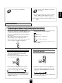
Use this function to automatically search and receive
the desired program type while listening to a RDS
station.
1
In the RDS mode.
If one of the preset stations is broadcasting the
selected program type, it will be tuned in while
listening to a RDS station.
If the station stops broadcasting the selected program
type, the tuner will find other stations repeatedly.
If no station is found, the previous RDS station will
be tuned in.
When the PTY indicator goes off, repeat again from
the above step 1.
press the EON PTY button to cancel the EON PTY
mode.
EON PTY
Program type is displayed and the PTY indicator is
flickering.
EON TA
DISPLAY
In the FM mode.
Use this function to automatically search and receive
the traffic announcement while listening to traffic
program.
DISPLAY
In the TP mode.
EON TA
Each time this button is pressed, the display mode
changes as follows;
Traffic program is displayed and the TA indicator
lights up.
If the preset station broadcasting traffic announcement
is found, it will be tuned in while listening to the traffic
program.
If the station stops broadcasting traffic announcement,
the tuner will find other stations repeatedly.
If no station is found, the previous traffic program
station will be tuned in.
Press the EON TA button to cancel the EON TA mode.
Program
→ Frequency → Service name →
(PS)
Program
Clock
Radio
Type → Time → Text
(PTY)
(CT)
(RT)
If the signals are too weak or no RDS service is
available, “NO NAME”, “NO PTY”, “NO TIME”
or “NO TEXT” will be displayed.
23
ENGLISH
EON PTY (EON: Enhanced Other Networks
information)
ENGLISH
RECORDING
The analog signals from the 6 CH DIRECT inputs as well as the digital signals from the coaxial or optical digital
input can be heard but cannot be recorded.
The volume and tone (bass, treble) settings have no effect on the recording signals.
Recording with TAPE MONITOR
1
POWER
AUDIO
2
Select the desired input as a recording
source except for TAPE MONITOR.
VIDEO
CD
TUNER
VIDEO1
P.SCAN
1
2
3
6
7
8
4
5
9
0
REPEAT
INTRO
DISC
CD
A< <B
3
A
DECK SEL.
B
AUX
VIDEO2
or
DECK
PRESET
USER
FILE
CD
TUNER
VIDEO1
AUX
T.MON
VIDEO3
DISPLAY
EQUALIZER
TAPE MON. VIDEO2
6CH DIRECT
STEREO
AUTO
DSP MODE
INPUT
SELECTOR
CH SEL.
T.TONE
VIDEO3
D.TIME
ADJUST
DISPLAY
SLEEP
Start recording on the TAPE MONITOR.
CH LEVEL
MASTER
Start play on the desired input.
MUTE
SYS
For tape monitor function, refer to “TAPE
MONITOR function” on page 11.
Be sure that “TAPE M” goes off.
Dubbing from video components onto
VIDEO 1
1
2
Start recording on the VIDEO 1.
Select VIDEO 2 or VIDEO 3 as a recording
source.
POWER
VIDEO
P.SCAN
1
2
3
6
7
8
4
5
9
0
REPEAT
INTRO
DISC
3
CD
A< <B
A
DECK SEL.
B
VIDEO2
or
DECK
PRESET
USER
CD
FILE
TUNER
AUX
T.MON
VIDEO1
DISPLAY
EQUALIZER
TAPE MON. VIDEO2
6CH DIRECT
STEREO
VIDEO3
AUTO
DSP MODE
INPUT
SELECTOR
CH SEL.
T.TONE
VIDEO3
Start play on the VIDEO 2 or the VIDEO 3.
D.TIME
ADJUST
DISPLAY
SLEEP
CH LEVEL
MASTER
MUTE
SYS
The audio and video signals from the VIDEO 2 or the
VIDEO 3 will be dubbed onto the VIDEO 1 and you
can enjoy them on the TV set and from the speakers.
Dubbing the audio and video signals
separately onto VIDEO 1
2
Example) When dubbing the VIDEO 2 video signal
and the CD audio signal separately onto
VIDEO 1.
Select CD as an audio recording source.
POWER
AUDIO
P.SCAN
1
2
3
6
7
8
4
5
9
0
REPEAT
INTRO
DISC
CD
A< <B
1
A
Select VIDEO 2 as a video recording source.
DECK SEL.
B
CD
DECK
PRESET
CD
or
AUX
USER
FILE
TUNER
VIDEO1
T.MON
VIDEO3
STEREO
AUTO
D.TIME
CH SEL.
ADJUST
CH LEVEL
DISPLAY
POWER
SYS
P.SCAN
1
2
3
6
7
8
4
5
9
0
REPEAT
INTRO
DISC
CD
A< <B
A
DECK SEL.
VIDEO2
B
DECK
PRESET
CD
or
AUX
USER
FILE
TUNER
VIDEO1
T.MON
6CH DIRECT
VIDEO3
DISPLAY
EQUALIZER
TAPE MON. VIDEO2
STEREO
AUTO
DSP MODE
INPUT
SELECTOR
CH SEL.
T.TONE
D.TIME
ADJUST
CH LEVEL
DISPLAY
SLEEP
MASTER
MUTE
SYS
24
DSP MODE
INPUT
SELECTOR
T.TONE
VIDEO
DISPLAY
EQUALIZER
TAPE MON. VIDEO2
6CH DIRECT
SLEEP
MASTER
MUTE
4
Start play on the VIDEO 2 and the CD
respectively.
The audio signal from the CD and the video signal
from the VIDEO 2 will be dubbed and you can
enjoy them on the TV set and from the speakers.
Note : Be sure to observe the order of the above steps
1 and 2.
OTHER FUNCTIONS
Compressing the dynamic range (Dolby Digital sources only)
Each time this button is pressed, the mode changes
and disappears in 3 seconds as follows:
This function compresses the dynamic range of
previously specified parts of the Dolby Digital sound
track(with extremely high volume) to minimize the
difference in volume between the specified and nonspecified parts.
This makes it easier to hear all of the sound track
when watching movies at night at low levels.
When the digital signals from Dolby Digital program
source are input in available surround mode.
DYNR 0.0 : Off
DYNR 0.5 : Low compression
DYNR 1.0 : High compression
In some Dolby Digital software, this function may
not be available.
DYNAMIC
RANGE
Operating the sleep timer
Adjusting the brightness of the
fluorescent displays
The sleep timer allows the system to continue to
operate for a specified period of time before
automatically shutting off.
To set the receiver to automatically turn off after
the specified period of time.
POWER
P.SCAN
1
2
3
6
7
8
4
5
9
0
REPEAT
INTRO
DISC
CD
A< <B
A
DECK SEL.
B
DECK
PRESET
POWER
USER
CD
2
3
4
5
6
7
8
9
0
TUNER
AUX
VIDEO3
T.MON
INTRO
DISPLAY
A< <B
STEREO
AUTO
DECK SEL.
B
SYS
DECK
PRESET
CD
USER
TUNER
AUX
FILE
VIDEO1
T.MON
ADJUST
DISPLAY
DISPLAY
SLEEP
MASTER
MUTE
SYS
EQUALIZER
TAPE MON. VIDEO2
VIDEO3
DSP MODE
CH SEL.
T.TONE
D.TIME
CH LEVEL
6CH DIRECT
DISPLAY
EQUALIZER
INPUT
SELECTOR
CD
REPEAT
VIDEO1
TAPE MON. VIDEO2
6CH DIRECT
A
SLEEP
FILE
P.SCAN
1
DISC
STEREO
AUTO
DSP MODE
INPUT
SELECTOR
CH SEL.
T.TONE
D.TIME
ADJUST
DISPLAY
SLEEP
CH LEVEL
MASTER
MUTE
SYS
Each time this button is pressed, the brightness of
all fluorescent displays of Sherwood components
connected by the DIGI LINK III changes together
as follows;
→ ON → dim → OFF
Each time this button is pressed, the sleep time
changes and disappears in 3 seconds as follows;
→ 10 → 20 → 30 → 60 → 90 → OFF
Unit : minutes
While operating the sleep timer, “SLEEP” lights up.
When the sleep time is selected, all display panels
of Sherwood components connected by the DIGI
LINK III are dimly lit.
In the display OFF mode, pressing any button will
restore the display ON mode.
25
ENGLISH
3
Start recording on the VIDEO 1.
ENGLISH
Troubleshooting Guide
If a fault occurs, run through the table below before taking your receiver for repair.
If the fault persists, attempt to solve it by switching the receiver off and on again. If this fails to resolve the situation, consult
your dealer. Under no circumstances should you attempt to repair the receiver yourself. This could void the warranty.
PROBLEM
POSSIBLE CAUSE
REMEDY
No power
• The AC input cord is disconnected.
• Poor connection at AC wall outlet or the
outlet is inactive.
• Connect the cord securely.
• Check the outlet using a lamp or another
appliance.
No sound
• The speaker cords are disconnected.
• The master volume is adjusted too low.
• The MUTE button on the remote control is
pressed to ON.
• Speakers are not switched on.
• Incorrect selection of the input source.
• Incorrect connections between the
components.
• Check the speaker connections.
• Adjust the master volume.
• Press the MUTE button to cancel the
muting effect.
• Press the SPEAKER button to ON.
• Select the desired input source correctly.
• Make connections correctly.
No sound from the rear
speakers
• Surround mode is switched off(stereo
mode).
• Master volume and rear level are too low.
• A monaural source is used.
• Rear speaker setting is “N”.
• Select a surround mode.
• Surround mode is switched off(stereo
mode).
• Center speaker setting is “N”.
• Master volume and center level are too low.
• Select the desired surround.
• No antenna is connected.
• The desired station frequency is not tuned
in.
• The antenna is in wrong position.
• Connect an antenna.
• Tune in the desired station frequency.
• An incorrect station frequency has been
memorized.
• The memorized stations are cleared.
• Memorize the correct station frequency.
Poor FM reception
• No antenna is connected.
• The antenna is not positioned for the best
reception.
• Connect an antenna.
• Change the position of the antenna.
Continuous hissing noise
during FM reception,
especially when a stereo
broadcast is received.
• Weak signals.
• Change the position of the antenna.
• Install an outdoor antenna.
Continuous or intermittent
hissing noise during AM
reception, especially at night.
• Noise is caused by motors, fluorescent
lamps or lightning, etc.
• Keep the receiver away from noise
sources.
• Install an outdoor AM antenna.
Remote control unit does
not operate.
• Batteries are not loaded or exhausted.
• The remote sensor is obstructed.
• Replace the batteries.
• Remove the obstacle.
Other system components
do not react to remote
control commands.
• DIGI LINK connections are not made
properly.
• Make proper DIGI LINK connections.
No sound from the center
speaker
Stations cannot be received
Preset stations cannot be
received
26
• Adjust master volume and rear level.
• Select a stereo or surround source.
• Select the desired rear speaker setting.
• Select the desired center speaker setting.
• Adjust master volume and center level.
• Move the antenna and retry tuning.
• Memorize the stations again.
Specifications
DIGITAL AUDIO SECTION
Sampling frequency ................................................................................................................................. 32, 44.1, 48, 96 kHz
Digital input level
Coaxial, 75 Ω ........................................................................................................................................................... 0.5 Vp-p
Optical, 660 nm ................................................................................................................................................. -15~-21 dBm
FM TUNER SECTION
Tuning frequency range .................................................................................................................................... 87.5~108 MHz
Usable sensitivity, THD 3%, S/N 26 dB .................................................................................................................... 12.8 dBf
46 dB quieting sensitivity, mono/stereo ............................................................................................................. 20.2/45.3 dBf
Signal to noise ratio, 65 dBf, mono/stereo ................................................................................................................. 70/65 dB
Total harmonic distortion, 65 dBf,1 kHz, mono/stereo .............................................................................................. 0.5/0.8%
Frequency response, 30 Hz~15 kHz ............................................................................................................................. ±3 dB
Stereo separation, 1 kHz ................................................................................................................................................. 42 dB
Capture ratio ...................................................................................................................................................................... 4 dB
IF rejection ratio .............................................................................................................................................................. 80 dB
AM TUNER SECTION
Tuning frequency range .................................................................................................................................... 522~1611 kHz
Usable sensitivity ...................................................................................................................................................... 500 μV/m
Signal to noise ratio ......................................................................................................................................................... 40 dB
Selectivity ........................................................................................................................................................................ 25 dB
GENERAL
Power supply ................................................................................................................................................ AC 230 V, 50 Hz
Power consumption ........................................................................................................................................................ 200 W
Switched AC outlet ................................................................................................................................. TOTAL 100 W max.
Dimensions (W×H×D) ............................................................................ 440×141×330 mm(17-3/8×5-1/2×13 inches)
Weight (Net) .................................................................................................................................................... 9.9 kg(21.8 lbs)
Note: Design and specifications are subject to change without notice for improvements.
27
ENGLISH
AMPLIFIER SECTION
Power output, stereo mode, 6 Ω, THD 0.7%, 40 Hz~20 kHz .................................................................................. 2×100 W
Total harmonic distortion, 6 Ω, 100 W, 1 kHz ............................................................................................................... 0.09%
Intermodulation distortion
60 Hz : 7 kHz= 4 : 1 SMPTE, 6 Ω, 100 W ...................................................................................................................... 0.1%
Input sensitivity, 47 kΩ
Line (CD, TAPE, VIDEO) .......................................................................................................................................... 200 mV
Signal to noise ratio, IHF “A” weighted
Line (CD, TAPE, VIDEO) ............................................................................................................................................. 92 dB
Frequency response
Line (CD, TAPE, VIDEO), 20 Hz~50 kHz ........................................................................................................ +0 dB, -3 dB
Output level
TAPE REC, 2.2 kΩ ..................................................................................................................................................... 200 mV
PRE OUT(Front, Center, Rear, Subwoofer), 1 kΩ .......................................................................................................... 1.0 V
Bass/Treble control, 100 Hz/10 kHz ........................................................................................................................... ±10 dB
Surround mode, only channel driven
Front power output, 6 Ω, 1 kHz, THD 0.7 % ................................................................................................... 125 W+125 W
Center power output, 6 Ω, 1 kHz, THD 0.7 % .............................................................................................................. 125 W
Rear power output, 6 Ω, 1 kHz, THD 0.7 % .................................................................................................... 125 W+125 W
O P E R A T I N G I N S T R U C T I O N S
RD-6108/RD-6108R
AUDIO/VIDEO RECEIVER
5707-04735-001-0