1
Installation
Instructions
Gas Conversion Kit Natural-to-Propane
For All Condensing Furnaces, 2 Stage 80%
Variable Speed Furnaces, 2-Stage Non-Condensing
Furnaces and Fixed Capacity 80% Furnaces
KGANP2901ALL
NOTE: Read the entire instruction manual before starting the installation.
This symbol --, indicates a change since the last issue.
SAFETY CONSIDERATIONS
Installing and servicing heating equipment can be hazardous due to gas and electrical components. Only trained and
qualified personnel should install, repair, or service heating equipment.
Untrained personnel can perform basic maintenance functions such as cleaning and replacing air filters. Trained
service personnel must perform all other operations. When working on heating equipment, observe precautions in
the literature, on tags, and on labels attached to or shipped with the unit, and other safety precautions that may
apply.
Follow all safety codes. In the United States, follow all safety codes including the National Fuel Gas Code (NFGC)
NFPA No. 54-1999/ANS1 Z223.1-1999. In Canada, refer to the National Standard of Canada, Natural Gas and
Propane InstallationCodes (NSCNGPIC), CAN/CGA-B149.1 and .2-M00.
Wear safety glasses and work gloves. Have a fire extinguisher available during start-up, adjustment Steps, and
service calls.
Recognize safety information. This is the safety-alert symbol.
Z_
When you see this symbol on the furnace
and in instructions or manuals, be alert to the potential for personal injury.
Understand the signal words DANGER, WARNING, CAUTION, and NOTE. The words DANGER, WARNING, and
CAUTION are used with the safety-alert symbol. DANGER identifies the most serious hazards, which will result in
severe personal injury or death. WARNING signifies hazards, which could result in personal injury or death.
CAUTION is used to identify unsafe practices, which would result in minor personal injury, or product and property
damage. NOTE is used to highlight suggestions, which will result in enhanced installation, reliability, or operation.
//_
WARNING: This conversion kit shall be installed by a qualified service agency in accordance with
the manufacturer's instructions and all applicable codes and requirements of the authority having
jurisdiction. If the information in these instructions is not followed exactly, a fire, explosion, or production
of carbon monoxide may result causing property damage, personal injury, or loss of life. The qualified
service agency is responsible for the proper installation of this furnace with this kit. The installation is not
proper and complete until the operation of the converted appliance is checked as specified in the
manufacturer's instructions supplied with the kit.
Form: AG-GANP-29
Cancels: AG-GANP-27
Printed in U.S.A.
07-02
Pg. 1
Catalog NO.63GA-NP9
/_
AVERTISSEMENT:
Cette trousse
de conversion
ne dolt _tre install_e
que par le repr_sentant
d'un
organisme qualifid et conformement
aux instructions du fabricant
et _, tousles codes et exigences
pertinents de I'autoritd competente.
Les instructions
du present guide doivent _tre suivies afin de r_duire
au minimum au risque d'incendie ou d'explosion
de dommange materiels,
de blessure ou de mort,
L'organisme qualifi_ responsable
de I'installation addquate de cette trousse, L'installation
n'est pas
adequate ni complete tant que le bon fonctionnement
de I'appereil converti n'a pas _t_ v_rfid selon
les instructions du fabricant fornies avec la trousse.
INTRODUCTION
This instruction covers the installation of gas conversion kit Part No. KGANP2901ALL to convert the following
furnaces from natural gas usage to propane gas usage. See appropriate section for your furnace type.
--,o Section 1-- (Page 3) Models 58STA, 58STX, 58DLA, 58DLX, 310AAV, 310JAV, 311AAV, 311JAV, PG8MAA,
PG8JAA, 58CTA, 58CTX, 58CVA, 58CVX, 312AAV, 312JAV, 315AAV, 315JAV 33.3-Inch High, InducedCombustion, Hot-Surface Ignition. Single Stage, 2 Stage and Variable Speed Non-Condensing 4-Way Multipoise
Furnaces with 42,000 through !54,000 Btuh gas input rates.
-*o Section 2-- (Page 13) Models 58WAV, 58PAV, 58ZAV, 58RAV, 395CAV, 383KAV, 376CAV, 373LAV,
393AAV, 58YAV, PG8UAA, PG8DAA, 58DXT, 58TMA, 58TUA, 58UHV, 58UXT, 58UXV, 330AAV, 330JAV,
331AAV, 331JAV, 333BAV, and 333JAV 40-inch high, induced-Combustion, Hot-Surface Ignition, Single Stage, 2Stage and Variable-Speed, Non-Condensing Furnaces. This kit is designed for use in furnaces with 40,000 through
154,000 Btuh gas input rates.
-,°Section 3--- (Page 20) Models 58MCA, 58MSA, 58MXA, 340MAV, 345MAV, 350MAV, 490AAV, and PG9MAA,
58MVP, 58MTA, 355MAV, and 352MAV, 4-Way Multipoise, Hot Surface Ignition, Condensing Furnaces. This kit is
designed for use in furnaces with 40,000 through 140,000 Btuh gas input rates.
--,This kit is designed for use in the furnaces listed above. The gas valve will be a White-Rodgers 36E or 36F
series gas valve with either an electric control switch or a manual control knob.
--,IMPORTANT: This kit can replace conversion kit KGANP25012SP for furnaces listed in Sections 2 and 3, as
specified on unit rating plate, when gas valve is replaced with Two-Stage Gas Valve PIN EF33CW198 (WhiteRodgers 36E55). Replacement gas valve is available through RCD.
/_
-,WARNING: Improper installation, adjustment, alteration, service, maintenance, or use can cause
carbon monoxide poisoning, explosion, fire, electrical shock, or other conditions, which could result in
personal injury or death. Consult your distributor or branch for information or assistance. The qualified
installer or agency must use only factory-authorized kits or accessories when servicing this product.
Failure to follow instructions could result in serious injury, death or property damage.
Z_
WARNING: Gas supply MUST be shut off before disconnecting electrical power and proceeding with
conversion.
-2-
DESCRIPTION
AND
USAGE
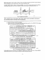
This kit is designed for use in the furnaces listed above. See Table 1 for kit contents. To accommodate many
different furnace models, more parts are shipped in kit than will be needed to complete conversion. When
installation is complete, discard extra parts.
Table 1-Kit Contents
DESCRIPTION
Main Burner Orifice (Drill Size 1.30mm)
Main Burner Orifice (Drill Size 1.25mm)
Main Burner Orifice (Drill Size No. 54)
Main Burner Orifice (Drill Size No. 55)
Main Burner Orifice (Drill Size No. 56)
Screw, Spoiler
Diverter Plate
Low Gas Pressure Switch (Propane) (LGPS)
Nipple
90 ° Street Elbow (1/8 in.)
Male x Female X Female Tee (1/8 in.)
Splice Connector (1/4 in. Male, Both Ends)
Splice Connector (3/16 in. Male, Both Ends)
Orange Wire Assembly (18 in.)
Orange Wire Assembly (12 in.)
Yellow Wire Assembly (6 in.)
Yellow Wire Assembly (14 in.)
Yellow Wire Assembly (16 in.)
Wire Tie
Conversion Rating Plate Label--Condensing Furnaces
Conversion Rating Plate Label--Non-Condensing Furnaces
Conversion Rating Plate Label--Non-Condensing Furnaces
Conversion Rating Plate Label--Non-Condensing Furnaces
Conversion Responsibility Label
Gas Control Conversion Label (adjusted)
Gas Control Conversion Label (converted)
Installation Instructions
Regulator Spring Kit (White---Propane-EF39ZW023) for WhiteRodgers 36C,36E and 36F Valve
PART NO.
LH32DB210
LH32DB209
LH32DB203
LH32DB201
LH32DB206
327593401
323184-301
HK02LB008
CA52JZ103
CA15RAO01
CA21JZO01
66175D55
HY89SC047
W182X23--04--018
W182X66--04--012
W182Y66--11--006
W182Y66--11--014
W182Y66--23--016
HY76TB125
327697-201
327697-204
327697-206
327697-207
327697-205
327697-202
327697-203
AG-GANP-29
QUANTITY
7
7
7
7
7
7
1
1
1
1
1
1
1
2
1
1
1
1
1
1
1
1
1
1
1
1
1
92-0659
INSTALLATION
---,SECTION 1-- INDUCED-COMBUSTION, HOT-SURFACE IGNITION, SINGLE-STAGE, TWO-STAGE AND
VARIABLE-SPEED, 33.3-INCH HIGH, NON-CONDENSING FURNACES
Single Stage Models
58STA
310AAV
58DLA
311AAV
58STX
310JAV
58DLX
311JAV
PG8MAA
PGSJAA
2--Stage Models
580TS
312AAV
580TX
312JAV
Variable Speed Models
58CVA
315AAV
58CVX
315JAV
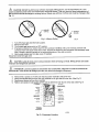
STEP 1--1NSTALL MAIN BURNER ORIFICES AND BURNER SPOILER SCREWS
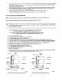
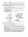
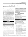
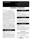
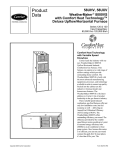
NOTE: Se_ Fig. 2 for component locationin UPFLOW orientation. Reorient component arrangement when furnace
is installed in other positions.
-3-
/'_
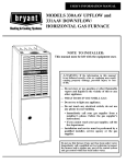
CAUTION: DO NOT re-drill burner orifices. Improper drilling (burrs, out-of round holes, etc.) can
cause excessive burner noise and misdirection of burner flames. This can result in flame impingement of
the burners and heat exchangers, causing failure. Obtain new orifices if orifice size must be changed. (See
Fig. 1.)
_RNER
ORIFICE
ORIFICE
Fig. 1--Burner Orifice
A96249
1.
2.
3.
4.
Turn off furnace gas and electrical supplies.
Remove outer door.
Turn furnace gas valve switch to OFF position.
If furnace is oriented in a manner that the vent connector interferes with burner removal, remove vent
connector from vent elbow inside the furnace. Support the remaining vent connector with temporary metal
wire or straps to prevent damage to the remaining portions of the vent connector.
5. Remove gas supply pipe from gas valve (If installed).
Disconnect wires from gas valve.
Z_
CAUTION: Label all wires prior to disconnection
improper and dangerous operation.
when servicing controls. Wiring errors can cause
Z_
ATTENTION: Lors des operations d'entretien des commandes, _tiqueter tousles ills avant de les
d6connecter. Toute erreur de c&blage peut _tre une source de danger et de panne.
6.
7.
8.
9.
Remove the 2 screws on the left side that secure the manifold to the burner box.
Swing out manifold from burners then pull manifold out of right side of burner box. (See Fig. 2)
Remove and discard orifices from manifold.
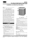
Refer to conversion kit rating plate 327697-204 to determine main burner orifice size. (See Fig. 9)
_NC_JCER MOTOR
,_ _
/
VENTLIMIT
ELBOW
M$4N
_TCH
pRESSURe J_
SWITCH
FLUE _f
C_LLIECTOR
S_EGtI_D
SWlT_I
8OX
_ J
GASMALVE J
i
M_UAL
RES_
PlOT _JRF_E
IGt_TER
CONTRO L
J
;
BLOWE_ DOOR
S,_,_ETY S_1TC,H
_-
-
BLOWER h=ND
MOTOR
\
Rp3Lt,K3 pLt_T E
NOT SHOWN
(LOCATEO ON
6LOWER DOOR}
A02041
Fig. 2--Component
-4-
Location
Gas input rate on furnace rating plate is for installations at altitudes up to 2000 ft. In the USA.,
altitudes above 2000 ft must be reduced by 4 percent for each 1000 ft above sea level.
the input rating for
In Canada, the input rating must be derated by 10 percent for altitudes of 2000 ft to 4500 ft above sea level.
The Conversion Kit Rating Plate accounts for high altitude derate.
10. Install main burner orifices. Do not use Teflon tape. Finger-tighten orifices at least 1 full turn to prevent
cross-threading, then tighten with wrench. There are enough orifices in each kit for largest furnace. Discard
extra orifices.
11. To
a.
b.
c.
d.
e.
f.
g.
h.
install burner spoiler screws, follow the following steps:
Disconnect Hot Surface Ignitor (HSI) wires from HSI
Disconnect Flame Sensor wire from Flame Sensor
Slide one-piece burner assembly out of slots on sides of burner box
Remove the Hot Surface Ignitor (HSI) and bracket from the burner assembly
Remove the flame sensor from the burner assembly
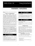
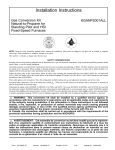
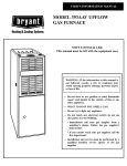
Locate the dimple on each burner venturi tube
Drill a 3/32" hole in each dimple
Install a spoiler screw in each drilled hole as straight as possible
SPOILER SCREW
Drill out
3/32"
drillwith
bit.
==t
BURNER
[
A02196
A85157
Fig. 3--Location of Dimple for Spoiler Screw
NOTE: Models 58CTX, 58CVX, 58DLX, 58STX, 310JAV, 311JAV, 312JAV, 315JAV and PG8JAA are supplied
with NOx emissions-reduction devices necessary for use with Natural Gas in NOx emissions-regulated areas.
/_
CAUTION: Furnace models 58CTX, 58CVX, 58DLX, 58STX, 310JAM, 31t JAM, 312JAM, 315JAV and
PG8JAA MUST have low NOx devices removed prior to operating furnace on propane gas.
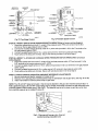
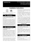
12. For NOx device removal, follow the following additional steps:
a. Remove the screw underneath the heat exchanger inlet that secures the NOX device in the heat
exchanger (see Fig. 4)
b. Use a pair of needle nose pliers to remove the NOx device. Squeeze the sides of the device if
necessary to remove from the heat exchanger.
c. Re-install screw in hole underneath heat exchanger inlet.
Fig. 4--NOx
Device Location
-5-
A02195
NOTE: It is very IMPORTANT to re-install the NOx bracket mounting screw.
d
Repeat steps "a" thru "c" for each heat exchanger
13. Re-install burner assembly by:
a. Attach flame sensor to burner assembly
b. Install HSI and bracket to burner assembly
c. Insert one-piece burner in slot on sides of burner box and slide burner back in place.
d. Re-attach HSI wires to HSI. Verify Ignitor 1o Burner alignment (See Fig. 30)
e. Re-attach Flame sensor wire to Flame Sensor.
15. Reinstall manifold by inserting right end of manifold into opening in right side of burner box.
16. Swing manifold into burner assembly and insert orifices into openings on burners.
17. Verify that orifices are fully inserted into burners and burners are fully seated in burner box.
18. Secure manifold to left side of burner box, verifying that green ground wire is reattached to burner box.
19. Reconnect wires to gas valve per the wiring diagram supplied with the unit.
NOTE: Failure to attach ground wire to gas manifold
no heat condition.
on burner box will result in loss of flame signal resulting
in a
NOTE: Use propane-gas resistant pipe dope to prevent gas leaks. DO NOT use Teflon tape.
STEP 2A--CONVERT
SINGLE STAGE GAS VALVE
NOTE: The following furnaces must have the regulator spring replaced in the gas valve:
58STA
58DLA
58STX
58DLX
1.
2.
3.
4.
5.
PG8MAA
PG8JAA
310AAV
311AAV
310JAV
311JAV
Be sure main gas and electrical supplies are off.
Remove regulator seal cap. (See Fig. 5A.)
Remove adjustment screw and natural gas regulator spring (silver).
Install propane gas regulator spring (white) in gas valve.
Turn regulator adjustment screw in 6 turns. Go to Step 3.
NOTE: DO NOT reinstall regulator seal cap at this time.
STEP 2B--PRE-ADJUST
2--STAGE GAS VALVE
NOTE: The following furnaces DO NOT need to have the regulator spring replaced in the gas valve. BUT the valve
MUST be pre-adjusted for propane applications:
58CTS
58CTX
312AAV
312JAV
58CVA
58CVX
315AAV
315JAM
Z_
CAUTION: The gas valve must be pre-adjusted before operating on propane gas. Failure to follow
this caution could result in excess underfire and flashback. If left this way sooting and corrosion will occur
leading to early heat exchanger failure.
1. Be sure gas and electrical supplies to furnace are off.
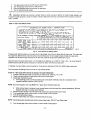
2. Rempve caps that conceal adjustment screws for high- and low-heat stage gas-valve regulators. (See Fig.
5B)
3. Turn low-heat stage adjusting screw (3/32-in. hex allen wrench) clockwise (in) t full turn. This will
increase the manifold pressure closer to the propane low-heat set point.
-6-
4.Turnhigh-heatstageadjusting
screw(3/32-in.
hexalienwrench)clockwise(in}2 full
turns. This will
increase the manifold pressure closer to the propane high-heat set point.
a. Replace caps that conceal gas-valve regulator adjustment screws. Go to Step 3.
- ON/OFF
SWITCH
ADJUSTMENT
ALLEN SCREW
(UNDER CAP}
ADJUSTMENT
ALLEN
SCREW
(UNDER
CAP)
PLUG BUTTON
(2-STAGE AND
VARIABLE-SPE ED,
NON.-_ONDENS)NG
FURNACES ONLY)
"- o'oJ
,o,0,,
i
MANIFOU
PRESSURE
TAP
BURNER ENCLOSURE
REFERENCE PRESSURE TAP(2,STAG_
AND VARJABLE-SPEED, CONDENSING
FURNACE_ ONLY}
A01069
A01073
Fig. 5A--Single
STEP 3--INSTALL
Stage Gas Valve
Fig. 5B-- Two-Stage Gas Valve
LOW GAS PRESSURE SWITCH (LGPS)
NOTE: The inlet gas pipe must be disconnected from valve so pressure switch can be installed.
NOTE: Use propane-gas-resistant pipe dope on all connections to prevent gas leaks. DO NOT use Teflon tape.
1. Be sure main gas and electric supplies to furnace are off.
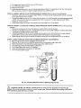
2. Remove 1/8-in. pipe plug from inlet pressure tap on gas valve. (See Fig. 6.) DO NOT DISCARD 1/8" PLUG
3. Apply pipe dope sparingly to one end of 1/8" brass male coupling (provided in kit) and install the doped
end in 1/8-in. tapped opening in gas valve inlet pressure-tap. Tighten fitting with a small open-end wrench.
(See Fig. 6)
I/8" brass coupling
Fig. 6A_as
Valve Inlet Pressure
Tap
Fig. 6B--LGPS
A02198
-7-
Installed
A02211
4.
5.
6.
7.
Apply pipe dope sparingly to opposite end of the 1/8" brass coupling (provided in kit). Install the female end
of the female x female x male tee on the brass coupling. Tighten coupling finger tight. Use a small openend wrench for final tightening.
Apply pipe dope sparingly to male end of brass tee. Install propane low gas pressure switch (provided in
kit) on male end of the female x female x male tee. Tighten switch finger tight. Use a small open-end
wrench on base of pressure switch for final tightening.
Connect a manometer to the open end of the tee installed in the gas valve. (See Fig. 6)
Apply pipe dope sparingly to end of inlet gas pipe and reconnect pipe to gas valve.
STEP 4--CHECK
INLET GAS PRESSURE
NOTE: This kit is to be used only when inlet gas pressure is between 11.0-in. w.c. and 13.6-in. w.c.
Verify manometer is connected to inlet pressure tap on gas valve. (See Fig. 6A)
Z_
CAUTION: DO NOT operate furnace more than 1 minute to check inlet gas pressure, as conversion
is not complete at this time.
For Two-Stage furnaces, perform the following on the control board:
a. Turn LHT switch on furnace control to ON (See. Fig. 7C)
For Variable Speed furnaces, perform the following on the control board:
a. Turn Setup Switch SW1-2 on furnace control ON (See Fig. 7D)
2. Turn on furnace power supply.
3. Turn gas supply manual shutoff valve to ON position.
4. Turn furnace gas valve switch to ON position.
5a. Jumper R-W thermostat connections on the Single Stage furnace control (See Fig. 7A or 78) or
5b. Jumper R-WAN1 and R-W2 thermostat connections on the 2-Stage and Variable Speed furnace control
(See Fig. 7C or 7D.). The two-stage algorithm must be removed to force furnace to high heat operation.
6. When main burners ignite, confirm inlet gas pressure is between 11.0-in. w.c. and 3.6-in. w.c.
7. Remove jumper across thermostat connections to terminate call for heat.
8. Turn furnace gas valve switch to OFF position.
9. Turn gas supply manual shutoff valve to OFF position.
10. Turn off furnace power supply.
11. Remove manometer.
12. Apply pipe dope sparingly to end of inlet gas pipe plug and install in unused end of 1/8" tee. Use a small
back-up wrench on tee when tightening gas inlet pipe plug. (See Fig. 6)
_,_*l_m
O= F _
L_
CO_O_EN_
TEST
i
A02100
A02142
Fig. 7A-_tandard
Single Stage
Control
Fig. 7B-Deluxe Single Stage Control
-g.
.o .....
0,
A02016
A02017
Fig. "/D-Variable
Fig. 7C-Two Stage Control
Speed
Control
STEP 5A--MODIFY SINGLE STAGE PRESSURE SWITCH WIRING (Refer to furnace wiring diagram)
1. Disconnect yellow wire from the N.O. contact of the pressure switch PRS and connect it to the NO.
terminal on the low gas pressure switch, LGPS.
2. Connect the insulated straight terminal of the 16-in. yellow wire (provided in kit) to the C terminal on the
low gas pressure switch, LGPS.
3. Connect insulated flag terminal of 16-in. yellow wire to the N.O, terminal to pressure switch PRS.
4. Route yellow wires along wire harness. Secure with wire tie provided in kit. Go to Step 6
STEP 5B--MODIFY 2--STAGE AND VARIABLE SPEED PRESSURE SWITCH WIRING (Refer to furnace
wiring diagram)
1, Disconnect yellow wire from the N.O. contact of the low-heat pressure switch LPS and connect it to the
N.O. terminal on the low gas pressure switch, LGPS.
2. Connect insulated straight terminal of 16-in, yellow wire (provided in kit) to C terminal on low gas pressure
switch LGPS.
3. Connect insulatedflag terminal of 16-in. yellow wire to N.O. terminal to low pressure switch LPS.
4. Route yellow wires along wire harness• Secure with wire tie provided in kit. Go to Step 6.
STEP 6---CHECK FURNACE OPERATION AND MAKE NECESSARY ADJUSTMENTS
1. Be sure main gas and electric supplies to furnace are off.
2. Remove 1/8-in. pipe plug from manifold pressure tap on downstream side of gas valve. (See Fig. 5A or 5B)
3. Attach manometer to manifold pressure tap on gas valve.
NOTE: The 1/8 inch NPT street ell included in the kit may be attached to the gas valve manifold pressure tap or a
field supplied 90 degree 1/8 inch NPT barbed fitting may be simplify manometer connection to gas valve when vent
connector passes inside furnace casing. (See Fig 8.) The street ell may be left in place on gas valve when plug
from manifold pressure tap in installed in street ell.
A02197
Fig. 8 - Plug removed from gas valve. Street ell
installed and plug reinstalled in ell.
-9-
4.
5.
6.
7.
Turn gas supply manual shutoff valve to ON position.
Turn furnace gas valve switch to ON position.
Check all threaded pipe connections for gas leaks.
Turn on furnace power supply.
WARNING: NEVER use matches, candles, flame, or other sources
a soap-and-water
solution to check for leaks. Failure to follow this warning
injury, or death.
of ignition to check for gas leakage. Use
could result in fire, explosion, personal
STEP 7--SET GAS INPUT RATE
-/
/
CONVERSION KIT RATING PLATE - CARRIER CORE
THrS
APPL!ANCE
PROCEDURES
EXISTING
hOTE
NAS
BEEN
CONVERTED
TO
USE
P_OPANE
USE 74,3T£ SL.PPLIED BY CAR_IER
I:_JNG
pLA_E
Fufr_oB 98S _t_
f_
FOR
on ra_
APPLIANCE
_I_
MODEL
FO_
CORPOR_JON
NO
is i_ ='_1_
GAS
AND
FUEL
REFER
TO
KIT
INSTRUCTIONS
AND INSTALLED BY OUALIF_ED PERSONNEL
INPUT
"_
FOR
CONVERS_Q_
SEE
%_'ING
up to 21)30ft _
In USA
_8
_
b_e tnpuEra_r_ I_
_I_O_S
abo_
2_
n rau_4
=gELUSED P_OPANEGAS
KIT NO KGANP2901ALL
!SUPE_SEO_S
KGANP2701LPS, KGANP2801FS0)
ALTITUDE
APPLIANCE
MODELS
3iS
JAY,
312JA_
580TA,
58OVA.
•
For
Orlf_e NO
_nfld Press
315AAV,
Odfice No
58CTX,
Antld
5_CVX.
Cafladi_l
INLET PRESSURE (rain • max): 110
iNSTALLATION
20_1 3001
4001
Io 3000 to 40C_ to 5000
310AAV, 310JAV, 311AAM
311JAM 58STA, 58STX.
58DLA, 58DLX,
PG8MAA,
PG8JAA
312AAM
OF
from
2000
1 ;30rim
11 0
55
Press
_10
_4igh I LOW
Ins_l_a1_ons
55
11 0
45_
130ram
11 O I
105
5 3
t_
u_e
SEA
500_
t 600_
to 6000 It° 7000
LEVE.)
700_
to 800_
- 136
USA
eco_
o 9000
in wc
*
to
900_
10000
1 25mm
1 25mm
56
56
56
11 0
11 0
10 5
110
I1 0
105
1 25mrn
1 25rnm
1 25ram
11 O /
1! O /
105
5 5
5 2
/
5 0
USA
ABOVE
1 25mm
105
1 30ram
/
5 8
to
1 3Dram
_FT
cot_m_l
20_1
to
3000
/
4 9
It
56
110
5 7
56
/
110
5,_
I
52
327697.204
105
/
4 8
R_MA_
A02192
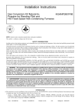
Fig. 9 - Conversion Kit Rating Plate
The gas-input rate for propane is the same as for natural gas. See furnace rating plate for input rate. The input rate
for propane is determined by manifold pressure and orifice size. On two-stage furnace models, the gas-valve
regulator must be set for high heat and set for low heat. (See kit rating plate 327697-204, Fig. 9)
Gas input rate on furnace rating plate is for installations at altitudes up to 2000 ft. In the U.S.A., the input rating for
altitudes above 2000 ft must be reduced by 4 percent for each 1000 ft above sea level.
In Canada, the input rating must be derated by 10 percent for altitudes of 2000 ft to 4500 ft above sea level.
The Conversion Kit Rating Plate accounts for high altitude derate.
STEP 7A--SET GAS INPUT RATE ON SINGLE STAGE FURNACES
1. Jumper R and W thermostat connections to call for heat. (See Fig. 7A or 7B)
2. Check manifold orifices for gas leaks when main burners ignite.
3. Adjust gas manifold pressure.
a. Turn adjusting screw counterclockwise (out) to decrease manifold pressure or clockwise (in) to
increase manifold pressure. (See Fig. 5A)
NOTE: Gas valve regulator seal cap MUST be in place when checking input rate.
b.
4.
5.
6.
7.
NOTE:
8.
When correct input is obtained, main burner flame should be clear blue, almost transparent. Be sure
regulator seal cap is in place when finished.
Remove jumper across R and W thermostat connections to terminate call for heat.
Turn furnace gas valve control switch or control knob to OFF position.
Turn off furnace power supply.
Remove manometer and replace manifold pressure tap plug.
Us_ propane-gas-resistant
pipe dope to prevent gas leaks. DO NOT use Teflon tape.
Turn furnace gas valve control switch or control knob to ON position.
-10-
9. Turnonfurnacepowersupply.
10.Setroomthermostat
tocallforheat.
11.Checkmanifold
pressure
tapplugforgasleakswhenmainburnersignite.
12.Observe
unitoperation
through2complete
heatingcycles.Seesequence
ofoperation
infurnace
Installation,
Start-upand Operating Instructions.
13. Set room thermostat to desired temperature.
STEP 7B--SET TWO-STAGE or VARIABLE SPEED GAS INPUT RATE
For Two-Stage furnaces, perform the following on the control board:
1. Make sure LHT switch on furnace control to ON. (See Fig. 7C)
2. Jumper R and W/W1 thermostat connection on furnace control
3. Check manifold orifices for gas leaks when main burners ignite. Go to Step 4.
For Variable Speed furnaces, perform the following on the control board:
1. Make sure Setup Switch SW1-2 on furnace control ON. (See Fig. 7D)
2. Jumper R and WAN1 thermostat connection on furnace control.
3. Check manifold orifices for gas leaks when main burners ignite. Go to Step 4.
4.
Adjust gas manifold pressure.
a. Remove caps that conceal adjustment screws for gas-valve regulators. (See Fig. 5B)
b. Jumper R, W/W1 thermostat connections on control. (See Fig. 7C or 7D.) Adjust low-heat input
c.
d.
e.
f.
g.
h.
5.
6.
7.
8.
rate manifold pressure for propane gas. (See kit rating plate 327697-204, Fig. 9) (Note: Gas valve
should already have been pre-adjusted, from prior steps for two-stage gas valve) Turn lowheat adjusting screw (5/64 hex allen wrench) counterclockwise (out) to decrease input rate or
clockwise (in) to increase input rate.
Jumper R, WNV1 and W2 thermostat connections on control. This keeps furnace in high-heat.
Adjust high-heat input rate manifold pressure for propane gas. (See kit rating plate 327697-204
Fig. 9) Turn high-heat adjusting screw.
(5/64 hex allen wrench) counterclockwise (out) to decrease input rate or clockwise (in) to increase
input rate.
Main burner flame should be clear blue, almost transparent.
Remove jumper across R, WNV1 and W2 after high-heat adjustment.
Replace caps that conceal gas-valve-regulator adjustment screws.
Turn setup switch LHT (two-stage) or SW-2 (variable speed) switch to OFF position.
Turn furnace gas valve switch to OFF.
Turn off furnace power supply.
Remove manometer and replace manifold pressure tap plug. (See Fig. 5A or 5B)
NOTE: Use propane-gas-resistant pipe dope to prevent gas leaks. DO NOT use Teflon tape.
9.
10.
11.
12.
13.
14.
Turn on furnace power supply.
Turn furnace gas valve switch to ON position.
Set room thermostat to call for heat.
Check pressure tap plug for gas leaks when main burners ignite.
When correct input is obtained, main burner flame should be clear blue, almost transparent. (See Fig. 29)
Observe unit operation through 2 complete heating cycles. See sequence of operation in furnace
Installation, Start-Up, and Operating Instructions.
15. Set room thermostat to desired temperature.
STEP 8---CHECK LOW GAS PRESSURE SWITCH OPERATION
The newly installed low gas pressure switch is a safety device used to guard against adverse burner operating
characteristics that can result from low gas supply pressure. Switch opens at not less than 6.5"w.c. and closes at
not greater, than 10.2"w.c.
This switch also prevents operation when the propane tank level is low which can result in gas with a high
concentration of impurities, additives, and residues that have settled to the bottom of the tank. Operation under
these conditions can cause harm to the heat exchanger system.
-I]-
This normally open switch closes when gas is supplied to gas valve under normal operating pressure. The closed
switch completes control circuit. ShouJd an interruption or reduction in gas supply occur, the gas pressure at switch
drops below low gas pressure switch setting, and switch opens. Any interruption in control circuit (in which low gas
pressure switch is wired) quickly closes gas valve and stops gas flow to burners.
When normal gas pressure is restored, the system must be electrically reset to re-establish normal heating
operation.
Before leaving installation, observe unit operation through 2 complete heating cycles. During this time, turn gas
supply to gas valve off just long enough to completely extinguish burner flame, then instantly restore full gas
supply. To ensure proper low gas pressure switch operation, observe that there is no gas supply to burners until
after hot surface ignitor begins glowing.
STEP 9--LABEL APPLICATION
Outer
_=_ _
0oar
--..
_:== _==
...ooq
t
Factory
Clearance
Label
i
Appiy Con version
ResponsibilityLabel
on exterior of door
_actory lnforrnation
Label
Apply Conversion
Rating Plate on
exteriorof door
ExistingWarning Label
Fig. 10--Label Application
1.
2.
3.
4.
5.
A02203
Fill in Conversion Responsibility Label (327697-205) and apply to Blower Access Door of furnace as
shown. (See Fig. 10) Date, name, and address of organization making this conversion are required.
Attach Conversion Rating Plate Label (327697-204, Fig. 9) to Outer Door of furnace.
Apply Gas Control Conversion Label to gas valve:
a. For single-stage gas valve apply label 327697-203 to gas valve. (Do not use 327697-202, which is
similar)
b. For two-stage gas valve apply label 326752-202 to gas valve, (Do not use 327697-203, which is
similar)
Check for correct normal operating sequence of the ignition system as described in furnace Installation,
Start-Up, and Operating Instructions.
Replace control access door.
-12-
INSTALLATION
SECTION 2-- INDUCED-COMBUSTION, HOT-SURFACE IGNITION, SINGLE STAGE, TWO-STAGE AND
VARIABLE-SPEED, 40-INCH NON-CONDENSING FURNACES MODELS
Single Stage Models
58PAV
383KAV
58WAV
395CAV
58RAV
373LAV
58ZAV
376CAV
STEP I--INSTALL
! PGaUAA
PGaDAA
393AAV
58YAV
Two-Sta_e
58TUA
58TMA
58UXT
58DXT
Models
330AAV
331AAV
330JAV
331JAV
i Variable
i 58UHV
i 58UXV
I
Speed Models
333BAV
333JAV
MAIN BURNER ORIFICES
NOTE: See Fig. 11A or 11B for component location.
1.
2.
3.
4.
Turn off furnace gas and electrical supplies.
Remove control access door.
Turn furnace gas valve switch to OFF position.
Remove gas supply pipe from gas valve (if installed).
L
J_'/_
!L_) pTRTM
C°NV' Sll° -
ENT
I
RATING\Ul
k_._.J_
III--GAS CO'NTROL
PLATE--hiL V
GASVALVE
' P0 R- ERGASVALVE
ll.aRS,ON
# X!WN
PLATE
_-_
_
CONVERNITOFNOL
/
BURNERS--.
zili_--_Z
FURNACE
CLEARANC;.F
_
_
F URRpAN_NCTE
BLOWER
J
u
_8&L
CONVERSION
COMPARTMENT
DOOR
j
CLEARANCE -/
/
_-- MANIFOLD
CONV ERLAs_)_ j
RESPONSIBIUTY
LABEL
RESPONSIBILITY
LABEL
A95459
A95460
Fig. 11A - Downflow and Downflow/Horizontal,
Standing Pilot, Fixed Speed, Non-Condensing
Furnace Component and Conversion Label
Z_
BRAO*ET
J
RATILANT_
MANIFOL
.....
#OL_#WN _NERS
M!lJ
--/'
Fig. 11B - Upflow and UpflowlHorizontal,
Standing Pilot, Fixed Speed, Non-Condensing
Furance Component and Conversion Label
CAUTION: Label all wires prior to disconnection when servicing controls. Wiring errors can cause
improper and dangerous operation.
Ak ATTENTION:
Lors des operations d'entretien des commandes, _tiqueter tousles fils avant de les
deconnecter. Toute erreur de c&blage peut _tre une source de danger et de panne.
5. ' Remove wires from gas valve. Note location for reassembly.
6. Remove wires from flame sensor and flame rollout safety swRch(es).
7. Disconnect harness from hot surface igniter.
8. Remove the 4 screws that secure the gas manifold to the burner assembly. Note the location of the
green ground wire attached to the manifold for reassembly,
9. Remove the manifold.
-13-
NOTE: Models 58DXT, 58UXT, 58UXV. 330JAV, 331JAV and 333JAV are supplied
devices necessary for use with Natural Gas in NOx emissions-regulated
areas.
with NOX emissions-reduction
For 58UXT, 58DXT, 58UHV, 330JAV, 331JAV and 333BAV, remove NOX emissions-reducing device as follows:
Using needle nose pliers, remove coil from bracket on each heat excnanger cell inlet plate. (See Fig. 12)
A9517t
Fig. 12 - Removal
Z_
CAUTION: Furnace models
NOX coils removed
of Low NOx
58DXT, 58UXT, 58UXV, 330JAV, 331JAV, and 333JAV, must have low
prior to operating
furnace on propane gas.
10. Remove and discard orifices from manifold.
11. Refer to convers=on kit rating plate 327697-206 (Single Stage, see Fig. 13) or 327697-207 (Two Stage,
see Fig. 14) to determine main burner orifice size.
f
CONVERStON
KIT RATING
PLATE - CARRIER
CORR
THIS APPLIANCE
HAS SEEN
CONVERTED
TO USE pROI_NE
GAS FOR FUEL
REFER
PROCEOURES
USE _¢*RTS SUPPLIED
BY CARRIER CORFOR_'ION
_,N0 INSTALLED BY
EXISTING
R,_NG
pL_£
FOR APPLIANCE k4ODEL NO
AND INPUT R/_4NG
TO KIT INSTRUCTIONS
QU_JFIE{_
PERSONNEL
NOTE Fuira_ @as =X_
¢_J1 rain@ _
tae o_ =a_,g pe,_ = I_ nstalalOll _
be ¢e(z_
by 4% t_
ea_
KIT NO
KGANP2931ALL
iO00 n aDo=e ,_
e,_
[SUPERSEDES
_ ¢_
b 2000 m aZo_e ,ea e,_
ele mul ramg rr,_
KGANP_701LP_
KGt_NF*2801FS0)
ALTITUDE
APPLIANCE
MODELS
O
2 ooo
373LA_
375CA_
5_RA_
5_ZAV
p_P_
383KAV
5_R=_
O I_Ce No I
Mnfld
pre_=l
393AAV
3_r'SCAV
58WA¥ 58vA_
PG_U,V _
On_ce
,
pfe$_
i
.
_o_ _ana_w_n
2000
10't, _
INSTALLATION
(FT
=¢ia_
ol _00
ABOVE
I
_,c'*_ 20_
I r_sl
_ 4500 _ I_J_e _a
(min
INLET
* ft_lX):
SEA
LEVEL
It'_
PRESSURE
110
. 136
i_
USA
v_
'
_001
to 400(
4001
to 5o0o
_0ol
to 6030
0 O01
_o 7o0(
7001
Io
8000
_1001
to
9O0C
55
110
55
110
55
105
55
100
1 _Smm
110
1 25 rnm
105
125 mm
100
_25mrr
125mn
125mm
56
56
105
IO0
I10
100
3_7597-205
REVA,,_
54
55
55
1ZSmm
10S
100
110
i
I0 45_)
tJ¢_
FUEL b_ED PROPAN£ GAS
100
i
I_Slal.a_ons fTo_
_
CONVERSION
_001
,_
3000
54
I10
NO;
Mn lId
OF
in US,K N
be _
"_
FOR
S£E
it
11 0
9001
_o 100o0
56
tl 0
,
t_e
USA.
cokJmn 2031
to
3000
t_
A02192
Fig. 13 - Conversion Kit Rating Plate - Single Stage Units
CONVERSION
THI_
APPLIANC_
H_
_N
CONVERTED
PROC_DURE_
USE FART_
SUPPUED
_Y
EXISTING RRING
ptJ3"E
FOR _pUAN_E
KIT RATING PLATE - CARRIER
TO USE pROFANE
GAS FOR FU£L
R_ER
C/_RIF_
CORPO_fON
AND INSTAL_D
By
MODEL NO AN_
INPUT R_rlNG
CORP.
TO KIT INSTRUCTIONS
QUA_JFIED PERSONf_L
INLET
KIT NO
KGA,NP2901ALL
AP PLIANC_
(SUPERSEDES
KGANP'2701LPS,
ALTITUDE
o
2001
MOOELS
_o
Onf_e
331AAV
5SDX_
331JAV,
58TM _.
NO
330JAV
58TUA
5BUXT
'
FOr
333SAV.
58UHV,
58UXV
_r_0_n
M_lfld p,_e_
_
to
110/
42
_o
1101
rise
(m_l
IF-"
ABOVE
5001
6001
503(
1 25mrr
4?
P_0F_N_ G,_
6000
to
1 25ram
10¸0/
SEA
70o0
56
tl0/
. max):
LEVEL
7001
Io
CONVERSION
PRESSURE
I1 0
. 136
8000_ k_
56
11¸0/
11
USA
e001
9000
56
_00f
*
_o1
to
10OO_
57
11¸0/
45
42
49
4_
42
$3
_ 25ram
10S!
1.25mrr
100/
5_
110/
56
11¸0/
56
1001
57
110/
57
110/
4 =
4 2
4 5
• 2
• 6
It
4o0_
125mm
125mm
110/
4 3
45_0
30o0
pJB. U_I):
INSTALLATION
3001
4001
IO0/
55
100/
I0
OF
55
47
Onhce NO
MnfldPreaA
Ir°m
to
11¸O/
High i Low
[¢_al_ll°_
2030
55
H_gh / Low
330AAV
333JAV.
KGANP2801F80)
"_
FOR
S_
USA
C01un"q
2001
4 9
T°
3000
II
53
• g
327697"207
REVA'_
A02190
Fig. 14 - Conversion Kit Rating Plate - Two-Stage Units
Furnace gas input rate on rating plate is for installationsat altitudes up to 2000 ft. In the U.S.A., the input rating for
altitudes above 2000 ft must be reduced by 4 percent for each 1000 ft above sea level.
-14-
In Canada, the input rating must be derated by 10 percent for altitudes of 2000 ft to 4500 ft above sea level.
The Conversion Kit Rating Plate accounts for high altitude derate.
12. Install main burner orifices. Do not use Teflon tape. Finger-tighten
orifices at least 1 full turn to prevent
cross threading and then tighten with wrench. There are enough orifices in each kit for largest furnace.
Discard extra orifices. Orifices of other sizes must be field supplied and are available through your
local distributor.
13. For units equipped with NOx devices, NOx coil must be removed. (See Fig. 12)
z_
CAUTION: DO NOT re-drill burner orifices. Improper drilling (burrs, out-of round holes, etc.) can
cause excessive burner noise and misdirection of burner flames. This can result in flame impingement of
the burners and heat exchangers, causing failure. Obtain new orifices if orifice size must be changed. (See
Fig. 1)
14. Reinstall manifold with 4 screws removed in Step 8. Burners should be checked for proper alignment
of the burner crossover slot. Verify green ground wire is attached to burner manifold
Note: Failure to attach ground wire to gas manifold on burner box will result in loss of flame signal resulting in a no
heat condition.
15. Reconnect wires to flame sensor and flame rallout safety switch(es). See the furnace wiring label to
ensure proper location of wires.
16. Reconnect ignitor wire connector. Verify Ignitor to Burner alignment, (See Fig. 31)
17. Reconnect wires to gas valve. See wiring label on furnace to ensure proper location of wires.
18. Reconnect gas supply pipe to gas valve using backup wrench on gas valve to prevent rotation and
improper orientation.
NOTE: Use propane-gas resistant pipe dope to prevent gas leaks. DO NOT use Teflon tape.
STEP 2A---CONVERT SINGLE STAGE GAS VALVE
NOTE: The following furnaces must have the regulator springreplaced in the gas valve:
58PAV
58WAV
58RAV
58ZAV
383KAV
395CAV
373LAV
376CAV
PG8UAA
PG8DAA
393AAV
58YAV
1. Be sure main gas and electrical supplies are off.
2. Remove regulator seal cap. (See Fig. 15A)
3. Remove adjustment screw and natural gas regulator spring (silver).
4. Install propane gas regulator spring (white) in gas valve.
5. Turn regulator adjustment screw in 6 turns.
NOTE: DO NOT reinstall regulator seal cap at this time.
STEP 2B--PRE-ADJUST
2 STAGE GAS VALVE
NOTE: The following furnaces DO NOT need have the regulator spring replaced in the gas valve. The valve MUST
be pre-adjUsted for propane applications:
58TUA
58TMA
330AAV
331AAV
58UHV
58UXV
-15-
333BAV
333JAV
58UXT
330JAV
58DXT
331JAV
!
CAUTION: The gas valve must be pre-adjusted before operating on propane gas. Failure to follow
this caution could result in excess underfire and flashback. If left this way, sooting and corrosion will
occur leading to early heat exchanger failure.
1,
2.
Be sure gas and electrical supplies to furnace are off,
Remove caps that conceal adjustment screws for high-and low-heat stage gas valve regulators. (See Fig.
15B)
3. Turn low-heat stage adjusting screw (3/32-in. hex allen wrench) clockwise (in) 1 full turn. This will
increase the manifold pressure closer
4. to the propane low-heat set point.
5. Turn high-heat stage adjusting screw (3/32-in. hex allen wrench) clockwise (in) 2 full turns. This will
increase the manifold pressure closer
6. to the propane high-heat set point.
7. Replace caps that conceal gas valve regulator adjustment screws.
ON/OFF
SWITCH
PRESSURE
TAP
LOW-HEAT
ADJUSTMENT
ALLEN SCREW
{UNDER CAP)
ADJUSTMENT
ALLEN SCREW
_ER
CAP}
(2-STAGE AND
VARIABLE-SPEED,
NON-CONDENSING
FURNACES
ONLY)
MANIFOLD
PRESSURE
_;
UG BU_ON
B
REFERENCE
PRESSURE TAP (2-ST.aG E
AND VARIABLE-SPEE
D, CONDENSING
FURNACES ONLY)
Fig. 15A - Single Stage Gas
STEP 3--INSTALL
Fig. 15B - 2-Stage Gas Valve
A0)069
LOW GAS PRESSURE SWITCH (LGPS)
NOTE: Use propane-gas-resistant
1.
2.
A010?3
pipe dope on all connections to prevent gas leaks. DO NOT use Teflon tape.
Be sure main gas and electric supplies to furnace are off.
Remove 1/8-in. pipe plug from inlet pressure tap on gas valve. (See Fig. 16) DO NOT DISCARD 1/8"
PLUG.
3. Apply pipe dope sparinglyto one end of 1/8" brass male coupling (provided in kit) and install the doped
end in 1/8-in. tapped opening in gas valve inlet pressure-tap. Tighten fittingwith a small open-end wrench.
(See Fig. 6A)
4. Apply pipe dope sparingly to opposite end of the 1/8" brass coupling (provided in kit). Install the female end
of the female x female x male tee on the brass coupling. Tighten couplingfinger tight. Use a small openend wrench for final tightening.
5. Apply pipe dope sparingly to male end of brass tee. Install propane low gas pressure switch (provided in
kit) on male end of the female x female x male tee. Tighten switch finger tight. Use a small open-end
wrench on base of pressure switch for final tightening. When pressure switch is tight, switch terminals
should point as shown in Fig. 6B relative to gas valve and clear controlcompartment access door.
6. Connect a manometer to the open end of the tee installed in the gas valve. (See Fig. 6A)
-]6-
STEP 4---CHECK INLET GAS PRESSURE
NOTE: This kit is to be used only when inlet gas pressure is between 1 1.0-in. w.c. and 13.6-in. wc..
1.
Z_
Verify manometer is connected to inlet pressure tap on gas valve. (See Fig. 6A)
CAUTION:
is not complete
2.
3.
4.
5a.
5b.
6.
7.
8.
9.
10.
11.
12.
DO NOT operate
furnace
more than
1 minute
to check
inlet
gas pressure,
as conversion
at this time.
Turn on furnace power supply.
Turn gas supply manual shutoff valve tO ON position.
Turn furnace gas valve switch to ON position.
Jumper R-W thermostat connections on the Single Stage furnace control
Jumper R-W/W1 and R-W2 thermostat connections on the 2-Stage and Variable Speed furnace control,
When main burners ignite, confirm inlet gas pressure is between 11.0-in. w.c. and 13.6-in. w.c..
Remove jumper across R to W or R-WNV1 and R-W2 thermostat connections to terminate call for heat.
Turn furnace gas valve switch to OFF position.
Turn gas supply manual shutoff valve to OFF position.
Turn off furnace power supply.
Remove manometer.
Apply pipe dope sparingly to end of inlet gas pipe plug and install in unused end of 1/8" tee. Use a small
back-up wrench on tee when tightening gas inlet pipe plug. (See Fig. 6A)
STEP 5A--MODIFY SINGLE STAGE PRESSURE SWITCH WIRING
1. Disconnect yellow wire from the NO. contact of the pressure switch PRS on the inducer housing and
connect it to the N.O. terminal on the low gas pressure switch, LGPS.
2. Connect the insulated straight terminal of the 16-in. yellow wire (provided in kit) to the C terminal on the
low gas pressure switch, LGPS.
3. Connect insulatedflag terminal of 16-in. yellow wire to the N.O. terminal to pressure switch PRS located on
inducer housing.
4. Route yellow wires along wire harness.
5. Secure with wire tie provided in kit. Go to Step 6.
STEP 5B--MODIFY TWO-STAGE AND VARIABLE SPEED PRESSURE SWITCH WIRING
1. Disconnect yellow wire from low-heat pressure switch LPS on inducer housing. Add 3/16-in. splice
connector to this wire.
2. Connect uninsulated terminal of 6-in. yellow wire (provided in kit) to splice connector. Connect other end to
C terminal on low gas pressure switch LGPS.
3. Connect insulated terminal of 14-in. yellow wire (provided in kit) to NO terminal on low gas pressure switch
LGPS. Connect other end to pressure switch LPS located on inducer housing.
4. Route yellow wires along wire harness, Secure with wire tie provided in kit. Go to Step 6.
STEP 6--CHECK FURNACE OPERATION AND MAKE NECESSARY ADJUSTMENTS
1. Be sure main gas and electric supplies to furnace are off.
2. Remove 1/8-in. pipe plug from manifold pressure tap on downstream side of gas valve. (Fig. 15A or 15B)
3. Attach manometer to manifold pressure tap on gas valve. (See Fig. 15A)
4. Turn gas supply manual shutoff valve to ON position.
5. Turn furnace gas valve switch to ON position.
6. Check all threaded pipe connections for gas leaks.
7. Turn on furnace power supply.
Z_
WARNING: NEVER use matches, candles, flame, or other sources of ignition to check for gas
leakage. Use a soap-and-water solution to check for leaks. Failure to follow this warning could result in
fire, explosion, personal injury, or death.
-I?-
STEP 7--SET GAS INPUT RATE
The gas-input rate for propane is the same as for natural gas. See furnace rating plate for input rate. The input rate
for propane is determined by manifold pressure and orifice size. Refer to the appropriate Conversion Kit Rating
Plate.
Gas input rate on furnace rating plate is for installations at altitudes up to 2000 ft. In the USA,
altitudes above 2000 ft must be reduced by 4 percent for each 1000 ft above sea level.
the input rating for
In Canada, the input rating must be derated by 10 percent for altitudes of 2000 ft to 4500 ft above sea level.
The Conversion
Kit Rating Plate accounts
for the high altitude
derate,
STEP 7A--SET GAS INPUT RATE ON SINGLE STAGE FURNACES
1. Jumper R and W thermostat connections to call for heat.
2. Check manifold orifices for gas leaks when main burners ignite.
3. Adjust gas manifold pressure. Turn adjusting screw counterclockwise(out) to decrease manifold pressure
or clockwise(in) to increase manifold pressure. Refer to Conversion Kit Rating Plate #327697-206.
(Single-Stage)
NOTE: Gas valve regulator seal cap MUST be in place when checking input rate.
4.
5.
6.
7.
8.
When correct input is obtained, main burner flame should be clear blue, almost transparent (See Fig. 29).
Be sure regulator seal cap is in place when finished.
Remove jumper across R and W thermostat connections to terminate call for heat.
Turn furnace gas valve control switch or control knob to OFF position.
Turn off furnace power supply.
Remove manometer and replace manifold pressure tap plug.
NOTE: Use propane-gas-resistant pipe dope to prevent gas leaks. DO NOT use Teflon tape.
9.
10.
11.
12.
13.
Turn furnace gas valve control switch or control knob to ON position.
Turn on furnace power supply.
Set room thermostat to call for heat.
Check manifold pressure tap plug for gas leaks when main burners ignite.
Observe unit operation through 2 complete heating cycles. See sequence of operation in furnace
Installation, Start-up and Operating Instructions.
14. Set room thermostat to desired temperature. Go to STEP 8.
For Two-Stage and variable speed furnaces, perform the following:
a) Turn switch#2 (low heat) on furnace control to ON (See. Fig. 17)
b) Jumper R and W/W1 thermostat connection on furnace control
c) Check manifold orifices for gas leaks when main burners ignite.
d) Proceed to STEP 7B.
. ELi=CTRONIC
AtR G'LE_.NER
i
LIGH
i
T
•
TWIN I TEST
TERMINAL
HU M .
o.
HIJMIDIFIER
C2,_.vAC 05
24-V_.T
LOw
OFt _
OELA¥
_--
,_(2,O_tl'_
_
H_.g
ONt._
FURNA[
SETUp
SWITCHES
A93348
A96402
Fig. ITA - Furnace Control for 2-Stage
Condensing Furnace and 2-Stage / Variable*Speed,
Non-Condensing
Furnaces
Fig. 17B - Setup Switches on Furnace Control for 2-Stage
Condensing Furnace and 2-Stage / Variable*Speed, NonCondensing Furnaces (Factory Settings Shown)
-18-
STEP 7B--SET
1.
2.
3.
4.
5.
6.
GAS INPUT RATE ON TWO-STAGE
AND VARAIBLE
SPEED FURNACES.
Adjust gas manifold pressure. Refer to Conversion Kit Rating Plate #327697-207 (Two-Stage)
a. Remove caps that conceal adjustment screws for gas-valve regulators. (See Fig. 15B)
b. Adjust low-heat input rate manifold pressure for propane gas. (See kit rating plate 327697-207,
see Fig. 14) Turn low-heat adjusting screw (5/64 hex allen wrench) counterclockwise (out) to
decrease input rate or clockwise (in) to increase input rate.
c. Jumper R and W2 thermostat connections on control. This keeps furnace in high-heat.
d. Adjust high-heat input rate manifold pressure for propane gas. (See kit rating plate 327697-207)
Turn high-heat adjusting screw (5/64 hex allen wrench) counterclockwise (out) to decrease input
rate or clockwise (in) to increase input rate.
e. Remove jumper across R and W2 after high-heat adjustment.
f. Replace caps that conceal gas-valve-regulator adjustment screws.
Remove jumper across R, W1 and W2 thermostat connections to terminate call for heat.
Turn setup switch to SW-2 to OFF position.
Turn furnace gas valve switch to OFF.
Turn off furnace power supply.
Remove manometer and replace manifold pressure tap plug.
NOTE: Use propane-gas-resistant
pipe dope to prevent gas leaks. DO NOT use Teflon tape.
7.
8.
9.
10.
11.
12.
Turn on furnace power supply.
Turn furnace gas valve switch to ON position.
Set room thermostat to call for heat.
Check pressure tap plug for gas leaks when main burners ignite.
When correct input is obtained, main burner flame should be clear blue, almost transparent. (See Fig. 29)
Observe unit operation through 2 complete heating cycles. See sequence of operation in furnace
Installation, Start-Up, and Operating Instructions.
13. Set room thermostat to desired temperature. Go to STEP 8.
STEP 8---CHECK LOW GAS PRESSURE SWITCH OPERATION
The newly installed low gas pressure switch is a safety device used to guard against adverse burner operating
characteristics that can result from low gas supply pressure. Switch opens at not less than 6.5"w.c. and closes at
no greater than 10.2"w.c..
This switch also prevents operation when the propane tank level is low which can result in gas with a high
concentration of impurities, additives, and residues that have settled to the bottom of the tank. Operation under
these conditions can cause harm to the heat exchanger system. This normally open switch closes when gas is
supplied to gas valve under normal operating pressure. The closed switch completes control circuit. Should an
interruption or reduction in gas supply occur, the gas pressure at switch drops below low gas pressure switch
setting, and switch opens. Any interruption in control circuit (in which low gas pressure switch is wired) quickly
closes gas valve and stops gas flow to burners.
When normal gas pressure is restored, the system must be electrically reset to reestablish normal heating
operation. Before leaving installation, observe unit operation through 2 complete heating cycles. During this time,
turn gas supply to gas valve off just long enough to completely extinguish burner flame, then instantly restore full
gas supply. To ensure proper low gas pressure switch operation, observe that there is no gas supply to burners
until after hot surface ignitor begins glowing.
STEP 9---LABEL APPLICATION (See Fig. 11A and 11B)
1. Fill in Conversion Responsibility Label (327697-205) and apply to inside of furnace as shown. Date, name,
and address of organization making this conversion are required.
2. Attach Conversion Rating Plate Label # 327697-206 (Single-Stage) or #327697-207 (Two-Stage) near
existing furnace rating plate.
3. Apply Gas Control Conversion Label:
a. 'For single-stage gas valve apply label 327697-203 to gas valve. (Do not use 327697-202, which is
similar)
b. For two-stage gas valve apply label 327697-202 to gas valve. (Do not use 327697-203, which is
similar)
- tg-
INSTALLATION
SECTION 3-- DIRECT-VENT, MULTIPOISE, HOT-SURFACE IGNITION,
SINGLE-STAGE, "rwo-STAGE AND VARIABLE-SPEED CONDENSING FURNACES
58MXA Single Stage Models
350MAV
PG9MAA
58MCA
58MSA
STEP I--INSTALL
340MAV
345MAV
Two-Stage Models
58MTA
352MAV
Variable Speed Models
58MVP
355MAV
490AAV
MAIN BURNER ORIFICES
NOTE: See Fig. 27 or 28 for component location in upflow orientation. Reorient component arrangement when
furnace is installed in other positions.
1. Turn off furnace gas and electrical supplies.
2. Remove main furnace door.
3. Turn furnace gas valve switch to OFF position.
4. Remove burner enclosure front.
5. Remove gas supply pipe from gas valve.
6. Remove wires from gas valve. Note location for reassembly.
Z_
CAUTION: Label all wires prior to disconnection when servicing controls. Wiring errors can cause
improper and dangerous operation.
Z_
ATTENTION: Lors des operations d'entretien des commandes, _tiqueter tous les fils avant de les
d6connecter. Toute erreur de c&blage peut _tre une source de danger et de panne.
7.
Remove burner-box pressure tube from gas-valve burner enclosure; reference pressure-tap fitting. (See
Fig. 28)
8. Remove screws that secure manifold to burner box and remove manifold, orifices, and gas valve as 1
assembly.
9. Remove and discard orifices from manifold.
10. Refer to conversion kit rating plate #327697-201 to determine main burner orifice size. (See Fig. 25)
Furnace gas input rate on rating plate is for installationsat altitudes up to 2000 ft. In the U.S.A., the input rating for
altitudes above 2000 ft must be reduced by 2 percent for each 1000 ft above sea level.
In Canada, the input rating must be derated by 5 percent for altitudes of 2000 ft to 4500 ff above sea level.
The Conversion Kit Rating Plate accounts for high altitude derate.
11. Install main burner orifices. Do not use Teflon tape. Finger-tighten orifices at least 1 full turn to prevent
cross threading, and then tighten with wrench. There are enough orifices in each kit for the largest furnace.
Discard extra orifices.
- 20 -
•/_
CAUTION: DO NOT re-drill burner orifices, improper drilling (burrs, out-of-round
holes, etc.) can
cause excessive burner noise and misdirection
of burner flames. This can result in flame impingement
of
the burners and heat exchangers,
causing failure. Obtain new orifices if orifice size must be changed. (See
Fig. 1)
NOTE: DO NOT reinstall the manifold,
orifices,
gas-valve
assembly,
and burner enclosure
front at this time.
STEP 2A--REPOSITION AIR SHUTTER (VARIABLE SPEED 355MAV060120 AND 58MVP120-20 ONLY)
1. Remove 2 screws holding air shutter in natural gas usage (NAT) position.
2. Reposition air shutter to propane gas usage (PROP) position. (See Fig. 18) Screws will now be located in
the shutter next to the PROP stamp.
NOTE: Air opening above burners will now be partially obstructed by air shutter.
GAS
POSSTION
AIR
SHUT£ER
A96264
Fig. 18 - Air Shutter in Propane Gas Usage (PROP) Position
(355MAV060120 and 58MVP120-20 Units Only)
STEP 2B--INSTALL DIVERTER PLATE, (Two-Stage and Variable Speed Condensing Furnaces ONLY)
1. Install diverter plate (provided in kit) above combustion air intake box as follows:
a. Remove front 2 screws on combustion air intake box. (See Fig. 19)
b. Remove combustion air intake box and set aside. (See Fig. 19)
c. If air diffuser has a solid center, remove center section of air diffuser.
d. • Remove burners.
e. • Remove center solid portion of sir diffuser. (See Fig. 20) Use tin snips to cut center portion of air
diffuser. Do not overly distort air diffuser. The air diffuser is Tog-L-Locked to burner box.
f. • Replace burners.
g. Install diverter plate Part No. 323184-301 provided in kit. (See Fig. 21)
h. Reinstall combustion air intake box and replace 2 screws to ensure diverter plate is properly
installed. (See Fig. 19)
....
~_
*.
A95443
Fig. 19 - Removing Combustion Air Intake Box
Fig. 20 - Removing Center Section of Air Diffuser
-21 -
PART
NO. 323184-301
A95450
Fig. 21 - Installing Diverter Plate
STEP 3--INSTALL MANIFOLD ASSEMBLY, ALL FURNACES
1. Reinstall manifold, orifice,and gas-valve assembly in burner box. Ensure manifold seal grommet is
installed properly and burners fit over orifices. Verify Ignitorto Burner alignment (See Fig. 32)
2. Reconnect wires to gas valve. Refer to furnace wiring schematic for proper wire location.
3. Reinstall burner box pressure tube to gas-valve regulator fitting.
4. Apply pipe dope sparingly to end of inlet gas pipe and reconnect gas supply pipe to gas valve using
backup wrench on gas valve to prevent rotation and improper orientation.
NOTE: Use propane-gas-resistant pipe dope to prevent gas leaks. DO NOT use Teflon tape.
NOTE: DO NOT reinstall burner enclosure front at this time.
STEP 4A---CONVERT AND PRE-ADJUST SINGLE STAGE GAS VALVE
NOTE: The following furnaces MUST have the regulator spring replaced in the gas valve:
58MCA
58MXA
58MSA
PG9MAA
340MAV
350MAV
345MAV
1. Be sure main gas and electrical suppliesare off.
2. Remove regulator seal cap. (See Fig. 22A)
3. Remove adjustment screw and natural gas regulator spring (silver).
4. Install propane gas regulator spring (white) in gas valve.
5. Turn regulator adjustment screw in 6 turns
NOTE: DO NOT reinstall regulator seal cap at this time.
STEP 4B--PRE-ADJUST
2-STAGE AND VARIABLE SPEED GAS VALVE
NOTE: The following furnaces DO NOT need have the regulator spring replaced in the gas valve, but the valve
MUST be pre-adjusted for propane applications:
I 58MTA
! 352MAV
I 58MVP
- 22 -
I 355MAV
CAUTION: The gas valve must be pre-adjusted before operating on propane gas. Failure to follow this
caution could result in excess underfire and flashback, If left this way sooting and corrosion will occur
leading to early heat exchanger
1
2.
3.
4,
5.
failure.
Be sure gas and electrical supplies to furnace are off.
Remove caps that conceal adjustment screws for high-and low-heat stage gas valve regulators. (See Fig.
22B)
Turn low-heat stage adjusting screw (3/32-in. hex allen wrench) clockwise (in) 1 full turn. This will
increase the manifold pressure closer to the propane low-heat set point.
Turn high-heat stage adjusting screw (3/32-in. hex allen wrench) clockwise (in) 2 full turns. This will
increase the manifold pressure closer to the propane high-heat set point.
Replace caps that conceal gas valve regulator adjustment screws.
ON/OFF
SWITCH
LOW-HEAT
ADJUSTMENT
(UNDER CAP)
E_"-_
_NLET
_-- PRESSUR
ALLEN
SCREW
-- HIGH-HEAT
ADJUSTMENT
(UNDER
TA_
CAP)
ALLEN SCREW
(2-STAGE AND
VARIABLE-SPEE D
NON-CONDENSING
FURNACES ONLY)
PLUG
BUTTON
PRESSURE
TAP
J
BURNER ENCLOSURE
REFERENCE PRESSURE TAP(2-STAGE
AND VARIABLE-SPEED,
CONDENSING
FURNACES ONLY)
A01073
A01069
Fig. 22B - Two Stage Gas Valve
Fig. 22A - Single Stage Gas Valve
STEP 5---INSTALL LOW GAS PRESSURE SWITCH (LGPS), ALL FURNACES
NOTE: The inlet gas pipe must be disconnected from valve so pressure switch can be installed.
NOTE: Use propane-gas-resistant
pipe dope on all connections to prevent gas leaks. DO NOT use Teflon tape.
1. Be sure main gas and electric supplies to furnace are off.
2. Remove 1/8-in. pipe plug from inlet pressure tap on gas valve. (See Fig. 6A) DO NOT DISCARD PLUG!
3. Apply pipe dope sparingly to the ends of the 1/8" brass male coupling (provided in kit) and install it in 1/8in. tapped opening in gas valve inlet pressure-tap. Tighten fitting with a small wrench.
4. Attach the female end of the female x female x male brass tee (provided in kit). Tighten fitting with a small
wrench so the male portion of the tee points out from the furnace.
5. Apply pipe dope sparingly to male end of bras tee. Install propane low gas pressure switch (provided in kit)
on nipple. After switch has been finger tightened, use small wrench on base of pressure switch for final
tightening. When pressure switch is tight, switch terminals should point as shown in Fig. 6A relative to gas
valve and clear control compartment access door.
6. Connect a manometer to the open end of the tee installed in the gas valve.
STEP 6-_HECK
INLET GAS PRESSURE
NOTE: This kit is to be used only when inlet gas pressure is between 11.0-in. wc and 13.6-in. wc.
- 23 -
1. Verify manometer is connected to inlet pressure tap on gas valve.
Z_
CAUTION: DO NOT operate furnace
is not complete at this time.
more than 1 minute
to check inlet gas pressure,
as conversion
2. Turn on furnace power supply.
3. Turn gas supply manual shutoff valve to ON position.
4. Turn furnace gas valve switch to ON position.
5. For single stage models, jumper R to W.
6. For two-stage and variable speed models, perform the following steps to force furnace control board to
high-heat operation.
For Two-Stage furnaces with HK42FZ017 board, perform the following
a. Turn LHT switch on furnace control to ON (See Fig. 7C)
on the control board:
For Two-Stage furnaces with HK42FZ010 or HK42FZ015 boards, perform the following on the
control board:
a. Turn switch #2 on furnace control board to ON. (See Fig. 17A & 17B)
For Variable Speed furnaces using HK42FZ012 control boards, perform the following on the control
board:
a. Turn Setup Switch SW1-2 on furnace control ON. (See Fig. 26)
For Variable Speed furnaces (4 thQtr of 2002) using HK42FZ022 control boards, perform the
following on the control board:
a. Turn Setup Switch SW1-2 on furnace control ON. (See Fig. 7D)
FLT (FAULT CODE
RECALL) --
LOW HEAT
ONLY--
BPH (BYPASS
HUMIDIFIER)EMERGENCY
HEATMZ (MULTI
ZONE) --
COMPONENT
TEST --
_-_Z
[Z3
_ _
,
_
i
HEATING
OFF
BLOWER .r
TIME DELAY _LI
m _
I
-_ m-r-]
ii
_ F'-F-I
]
A94299
Fig. 26 - Variable Speed Condensing Furnace Control Board
7.
8.
9.
10.
Jumper R-W/W1 and R-W2 thermostat connections on control.
When main burners ignite, confirm inlet gas pressure is between 11.0-in. w.c. and 13.6-in. w.c.
Remove jumper across R to W or R-W/W1 and R-W2 thermostat connections to terminate call for heat.
Turn furnace gas valve switch to OFF position.
- 24 -
11.
12.
13.
14.
Turn gas supply manual shutoff valve to OFF position.
Turn off furnace power supply.
Remove manometer.
Apply pipe dope sparingly to end of inlet gas pipe plug and install in unused end of 1/8" tee. Use a small
back-up wrench on tee when tightening gas inlet pipe plug. (See Fig. 6A)
STEP 7A--MODIFY SINGLE STAGE PRESSURE SWITCH WIRING (Refer to furnace wiring diagram)
1 Disconnect yellow wire from pressure switch (PRS) on furnace inducer housing. Attach wire to C terminal
on low gas pressure switch (LGPS).
2. Connect insulated terminal of 16-in. yellow wire (provided in kit) to NO terminal on low gas pressure switch
(LGPS). Connect other (flag style insulated) end to the C terminal on furnace pressure switch (PRS)
located on inducer housing.
3. Route wires along wire harness. Secure with wire tie provided in kit. Go to Step 8.
STEP 7B--MODIFY 2-STAGE AND VARIABLE SPEED PRESSURE SWITCH WIRING (Refer to furnace wiring
diagram)
1 Disconnect orange wire from low-heat pressure switch LPS on inducer housing.
2. Connect un-insulated terminal of 1 orange wire (provided in kit) to splice connector. Connect other end to
C terminal on low gas pressure switch LGPS.
3. Connect insulated terminal of second orange wire (provided in kit) to NO terminal on low gas pressure
switch LGPS. Connect other end to pressure switch LPS located on inducer housing.
4. Route orange wires along wire harness. If possible, secure with wire tie provided in kit. Go to Step 8.
STEP 8----CHECK FURNACE OPERATION AND MAKE NECESSARY ADJUSTMENTS
1. Be sure main gas and electric supplies to furnace are off.
2. Remove 1/8-in. pipe plug from manifold pressure tap on downstream side of gas valve.
3. Attach manometer to manifold pressure tap on gas valve. (See Fig. 24)
4. Turn gas supply manual shutoff valve to ON position.
5. Turn furnace gas valve switch to ON position.
6. Check all threaded pipe connections for gas leaks.
7. Turn on furnace power supply.
S
cHEURNER
ENCLOSURE
(REMOVECOVERWHEN
ECKING
PRESSURE)
GAS VALVE
PRESSURE
SWlTCH(E£)
(LOCA TION WILL VARY
DEPENDINGON MODEL)
_/
J._
MANOMETER
-
I --
- 7 -A01070
Fig. 24- Adjusting Manifold Pressure (Manifold Attachment)
Z_
WARNING: NEVER use matches, candles, flame, or other sources of ignition to check for gas
leakage. U_e a soap-and-water solution to check for gas leaks. Failure to follow this warning could result
in fire, explosion, personal injury, or death.
- 25 -
STEP 9--SET GAS INPUT RATE INFORMATION
The gas input rate for propane is the same as for natural gas. See furnace rating plate (See Fig. 25) for input rate.
The input rate for propane is determined by manifold pressure and orifice size. The gas-valve regulator must be set
for tow heat first and then set for high heat on 2-Stage and Variable Speed furnaces. The gas valve regulator must
also be adjusted on Single Stage furnaces
f
CONVERSION
THIS
ApptJAN_
PROCEDURES
SEE EXISTING
KiT NO
H,_
B_EN
CONVERTED
TO
KIT
USE
RATING
P_3PAN_
GAS
KGANI=2'_IALL
LSUPERS_DES
KG,_NP270_LP$
APPLIANCE
MODELS
O
I
1o 2#1
340MA_,
345MA_
350MAM
490AA'_
58MCA,
58M_A,
58MXA.
PGgMAA
{AJl rmldei sLze_ _XCEPT
1401
Or=lice NO
Mnfld Press
340MA_
Or#,ce No
350MA'_ 490AA_
58MXA,
58MCA,
PGgMAA
q _0 M0¢_ Sz_ O_LY_
352MAV
_8MTA,
.
--or
Or'f"_"
_SMVP
Mnl_
High
I_s_tlat_t_
No
[tom
_
,
4000
25_1m
I'
25mm
I
I_01
$1
45_3
ft
4 OOI
Io
_
CARRIER
TO
BY
K;T
CORR
5000
55
100
I_T
ABOVE
50OI
{¢1 _0oO;
t _5_tn
11 0
54
SEA
7000
1 25_m
_ O
54
CONVERSION
1 25rt',m
1 25mm
1 25 ....
1_01
51
110/
51
1101
S0
]ID/
50
2001
to
100
3000
e_0
125m,_1
tl 0
I1D
USA
700%
[o
54
I 25mm
eOl_r_n
100
LEVEL}
6001
to
1OO
Fig. 25 - Conversion
_O_
PERSONNEL
105
USA
"_
INSTrUCt'IONS
QUALIFIED
pROPh_NE GAS JNLET PRESSURE Imlt) . r_)
LAT]ON
54
t05
REFER
USED
55
10 0
_10/
54
Io
Io
54
1_0
I'
/Pte_I_I
Low
INSTA
3001
30_
S_
100
54
Mrtfld Pre_s
355MA'_
Canadk_n
$5
10 0
F,#EL
OF
2001"
Io
_EL
INSTALLED
=_NG
_D
INPUT
KGP.NP2_IFS01
ALTITUDE
PLATE
FOR
USE F_R_S SUPPLIED
9Y CARRIER _C,_pOR_K_N
R_ING
pLATE FOR APPU_CE
MODEL NO
AND
,
to
9001
_
_3 _(J000
54
125_ra
11 0
54
54
100
, 25mm
_]0/
50
ft
.
8°01
I 25r¢¢_
I1 0
100
25mm
. 136 1_
100
I 25mm
110/
49
327697201
1101
49
REVA
A02199
Kit Rating Plate
NOTE: Manifold pressure must always be measured with the burner enclosure front removed. (See Fig. 28)
Furnace gas input rate on rating plate is for installations at altitudes up to 2000 ft.
In the U.S.A., the input rating for altitudes above 2000 ftmust be reduced by 2 percent for each 1000 ft above sea
level.
In Canada, the input rating must be derated by 5 percent for altitudes of 2000 ft to 4500 ft above sea level.
The Conversion Kit Rating Plate accounts for high altitude derate.
STEP 10A--SET GAS INPUT RATE ON SINGLE STAGE FURNACES
1. Jumper R and W thermostat connections to call for heat. (See Fig. 7A or 7B)
2, Check manifold orifices for gas leaks when main burners ignite.
3. Adjust gas manifold pressure.
a. Remove burner box cover (See Fig. 28) and gas valve regulator seal cap that conceal adjustment
screw. (See Fig. 22A)
NOTE: Manifold pressure MUST always be measured with burner box cover removed.
b.
Turn adjusting screw counterclockwise (out) to decrease manifold pressure or clockwise (in) to
increase manifold pressure.
NOTE: Gas valve regulator seal cap MUST be in place when checking input rate.
c.
4.
5.
6.
7.
When correct input is obtained, main burner flame should be clear blue, almost transparent. (See
Fig. 29) Be sure regulator seal cap is in place when finished.
Remove jumper across R and W thermostat connections to terminate call for heat.
Turn furnace gas valve control switch or control knob to OFF position.
Turn off furnace power supply.
Remove manometer and replace manifold pressure tap plug.
NOTE: Use propane-gas-resistant pipe dope to prevent gas leaks. DO NOT use Teflon tape.
8.
9.
10.
11.
12.
Reinstall burner box cover.
Turn furnace gas valve control switch or control knob to ON position.
Turn on furnace power supply.
Set room thermostat to call for heat,
Check manifold pressure tap plug for gas leaks when main burners ignite.
- 26 -
13. Observe unit operation through 2 complete heating cycles. See sequence
Installation, Start-up and Operating Instructions.
14. Set room thermostat to desired temperature.
STEP 10B--SET
GAS INPUT RATE TWO-STAGE
AND VARIABLE
of operation
in furnace
SPEED FURNACES
Furnace control boards should have already been set up to respond to individual W1 and W2 signals (see
Step 6.6). Additional information can be found in furnace installation instructions.
1.
2.
3.
Jumper R and WAN1 thermostat connections to call for heat.
Check manifold orifices for gas leaks when main burners ignite.
Adjust gas manifold pressure.
a. Remove caps that conceal adjustment screws for gas valve regulators. (See Fig. 22B)
b. Adjust low-heat input rate manifold pressure for propane gas. (See kit rating plate #327697-201)
c. Turn low-heat adjusting screw (5/64 hex allen wrench) counterclockwise (out) to decrease input
rate or clockwise (in) to increase input rate.
d. Main burner flame should be clear blue, almost transparent. (See Fig. 29)
4. Jumper R and W2 on control center thermostat connections. This keeps furnace locked in high-heat
operation.
a. Adjust high-heat input rate manifold pressure for propane gas. (See kit rating plate #327697-201 )
b. Turn high-heat adjusting screw (5/64 hex allen wrench) counterclockwise (out) to decrease input
rate or clockwise (in) to increase input rate.
C.
Remove jumper across R, Wl, and W2 after high-heat adjustment to terminate call for heat.
e.
Replace caps that conceal gaswalve regulator adjustment screws.
f. Main burner flame should be clear blue, almost transparent. (See Fig. 29)
5. Turn setup switch LHT or SW-2 on control center to OFF position.
6. Turn furnace gas-valve switch to OFF position.
7. Turn off furnace power supply.
8. Remove manometer and reattach manifold pressure tap plug.
9. Reinstall burner enclosure front.
10. Turn furnace gas-valve switch to ON position.
11. Turn on furnace power supply.
12. Set room thermostat to call for heat.
13. Check pressure tap plug for gas leaks when main burners ignite.
14. Check for correct burner flame.
15. Observe unit operation through 2 complete heating cycles. See sequence of operation in furnace
Installation, Start-Up, and Operating Instructions.
16. Set room thermostat to desired temperature.
STEP 11--CHECK
LOW GAS PRESSURE SWITCH OPERATION
The newly installed low gas pressure switch is a safety device used to guard against adverse burner operating
characteristicsthat can result from low gas supply pressure. Switch opens at not less than 6.6" w c. and closes at
not greater than 10.2" w.c.
This switch also prevents operation when the propane tank level is low which can result in gas with a high
concentration of impurities, additives, and residues that have settled to the bottom of the tank. Operation under
these conditionscan cause harm to the heat exchanger system. This normally open switch closes when gas is
supplied to gas valve under normal operating pressure. The closed switch completes control circuit. Should an
interruption or reduction in gas supply occur, the gas pressure at switch drops below low gas pressure switch
setting, and switch opens. Any interruption in control circuit (in which low gas pressure switch is wired) quickly
closes gas valve and stops gas flow to burners.
When normal gas pressure is restored, the system must be electrically reset to re-establish normal heating
operation.
Before leaving installation, observe unit operation through 2 complete heating cycles. During this time, turn gas
supply to gas valve offjust long enough to completely extinguish burner flame, then instantly restore full gas
supply. To ensure proper low gas pressure switch operation, observe that there is no gas supply to burners until
after hot surface ignitor begins glowing.
- 27 -
STEP 12--LABEL
APPLICATION
NOTE: See Fig. 27 for label location.
GAS CONTROL
LABEL
RATING
PLATE
BURNER
"ENCLOSURE
RESPO
LABEL
-
GAS VALVE
CONTROL
FURNACE CONVERSION
RATING PLATE
Fig. 27 - Condensing
A01025
Furnace Label Location
1. Fill in Conversion Responsibility Label (327697-205) and apply to blower access panel as shown. Date,
name, and address of organization making this conversion are required.
2. Attach Conversion Rating Plate Label (327697-201, See Fig. 25) on blower shelf as shown.
3. Apply Gas Conversion Label.
a. For Single Stage Furnaces, apply label 327697-203 to burner box cover as shown. (Do not use
327697-202 which is similar)
b. For Two Stage and Variable Speed Furnaces, apply label 327697-202 to burner box cover as shown.
(Do not use 327697-203 which is similar)
4. Reinstall main furnace door.
BURNER
ENCLOSURE
=1,.
f,tANIFOLD
_BURNER
ENCLOSURE
REFERENCE
PRESSURETUBE
--
GASVAWE
--CONTROL
A01081
Fig. 28 - Muitipoise, Hot-Surface Ignition, Fixed-Speed, Condensing Furnace Component
Location (Upflow Orientation Shown)
- 28 -
BURNER
BURNER
A_9020
MANIFOLD
Fig- 29 - Burner Flame
9132" _
_" "
i
i
A02150
A02151
Fig. 30 - Position of Ignitor to Burner (Section 1}
- 29 -
_- 11/32"
L
BURNER
|
/
CELL
PANEL
_HOT
SURFACE
IGNITOR
ASSEMBLY
IGNITOR
7/8,,
_
BURNER
IGNITOR
ASSEMBLY
A93347
Fig. 31 - Position of Ignitor to Burner (Section 2)
I _/32"
ip_
CELL
PANEL
iGNITOR
ASSEMBLY
IGNITOR
ASSEMBLY
Fig. 32 - Position of Ignitor to Burner (Section 3)
- 30 -
A93260
-3l
-
Form: AG-GANP-29
Cancels: AG-GANP-27
Printed in U.S.A.
07-02
Pg. 32
Catalog No. 63GA-NP9