1
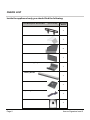
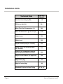
Operating & Installation Manual
Signature Inset 5
PLEASE RETAIN THIS GUIDE FOR FUTURE REFERENCE
BK075
EN 13240:2001+
Amd. A2:2004
Rev. 06
October2009
Part No. AFS1397
09
Congratulations on your choice of an Aarrow Stove.
More than 20 years experience has been put into the
development of our Signature Inset range to ensure ultimate
performance and years of trouble free use and enjoyment.
Every detail of the stove has been carefully designed and
engineered which is why we are so confident in the reliability
of our products.
Should you have any questions about our Signature Inset
stoves that are not covered by this manual, please contact
The Aarrow retailer in your area, or call our technical
support department on 0844 847 5107.
All Aarrow Signature Inset stoves are approved to
European Standard EN 13240 and CE marked.
These appliances listed within this manual have been
approved by HETAS Ltd as an intermittent operating
appliance for burning wood only.
Copyright 2009
Arada Ltd
This booklet has copyright and may not be
copied in whole, or part, or used for any
purpose other than that for which it is supplied
without express written consent from Arada Ltd
PLEASE NOTE— Arada has a policy of continuous product development and therefore we
reserve the right to amend the specification without prior notice.
Due to printing cycles, items or options may be described before they are generally available
or after they have ceased, so please check with your retailer or dealer.
Page 2
Aarrow Signature Inset 5
CONTENTS
INTRODUCTION
Page No.
OPERATING INSTRUCTION
Page No.
Warning Notice
4
Suitable Fuel
21
Safety Notices
5
Lighting The Stove
21
The Principle Of The Stove
5
Burning Wood
22
Reduced Burning
22
Check List
6-7
Data Plate Information
7
Over Firing & Chimney Fires
23
Technical data
8
Ash Removal
23
Air Inlet Controls
24
INSTALLATION
General Precautions
9
Fuel Retainer
25
Handling
9
Multi Purpose Operating Tool
26
Air For Combustion
9
Main Fire Door Handle
27
OPTIONAL EXTRA / ACCESSORIES
28
Hearth
Flues & Chimneys
9-10
11-12
SPARE PARTS LIST
29-30
31-32
Sealing the back of the Signature 5 stove
to the decorative fire surround
12
GUARANTEE
Firebox Liner Panels
13
GENERAL DIMENSIONS
33
Optional Securing Bolts
14
FACTORY CHECK LIST
34
Final Check
14
Building Control Consent Checklist
15
SERVICE & MAINTENANCE
Annual Maintenance
16
Cleaning
16
Chimney Sweeping
16
Door Glass
16
Outer Finish
16
Summer Storage / Non Usage
17
Adjusting The Door Hinges
17
Fuel Retainer Inspection
17
Fire Door Rope Replacement
18-19
Fire Door Glass Replacement
18-19
Disassemble The Primary Air Control
Service Record
Aarrow Signature Inset 5
19
20
Page 3
WARNING
IT IS A LEGAL REQUIREMENT THAT THE INSTALLATION OF ALL
NEW OR REPLACEMENT, WOOD OR SOLIDFUEL HEATING
APPLIANCES ARE REQUIRED TO OBTAIN BUILDING CONTROL
APPROVAL FROM YOUR LOCAL AUTHORITY OR THE
INSTALLATION WORK MUST BE CARRIED OUT THROUGH A
GOVERNMENT APPROVED COMPETENT PERSONS SCHEME
SUCH AS OPERATED BY HETAS.
IF IN DOUBT, CONTACT HETAS LIMITED
TELEPHONE NUMBER : 0845 634 5626
www.hetas.co.uk
THIS STOVE MUST NOT BE CONNECTED
TO A SHARED FLUE SYSTEM
TO ALL USERS
PETROLEUM COKE
SOME OF WHOSE BRAND NAMES ARE
‘CALCO’, ‘PETROCOKE’ AND ‘WONDERCO’
MUST NOT BE BURNED IN THIS APPLIANCE
BITUMINOUS HOUSE COAL
SHOULD NEVER BE USED IN YOUR STOVE
TO USE THESE FUELS WILL INVALIDATE
THE APPLIANCE GUARANTEE.
IF IN DOUBT CONTACT THE SOLID FUEL ASSOCIATION
TELEPHONE NUMBER 0845 601 4406
www.solidfuel.co.uk
Page 4
Aarrow Signature Inset 5
INTRODUCTION
SAFETY
THE PRINCIPLE OF THE STOVE
A fireguard conforming to BS 8423:2002
should be used in the presence of children
and old or infirm people.
Please note, this appliance should be used
with the fire door closed at all times except
when re-fuelling, initial lighting or de-ashing.
Your Aarrow stove is built to the highest
standard of craftsmanship using the best
materials and the most modern equipment
available. It is a highly efficient and sophisticated
piece of machinery and when properly installed
and operated it should provide a lifetime of
heating satisfaction.
Do not use aerosol sprays or any other
flammable materials near the appliance
under fire.
Do not fit an extractor fan in the same
room as the appliance.
Fire cement is caustic, hand and eye
protection should always be worn,
prolonged contact with the skin should be
avoided.
Arada Ltd will not be responsible for any
consequential or incidental loss or
injury however caused.
Before continuing any further, with the
installation of this appliance please read the
following guide to manual handling.
• Always obtain assistance when lifting the
appliance
• When lifting always keep your back straight,
•
•
•
•
bend your legs not your back
Avoid twisting at the waist. It is better to
reposition your feet.
Avoid upper body/top heavy bending. Do
not lean forwards or sideways when
handling the fire
Always grip with the palms of your hands
do not use your fingertips for support
Always keep the stove as close to the body
as possible as this will minimise the
cantilever action.
Aarrow Signature Inset 5
Safety is the most important consideration when
installing your fire. If not properly installed and
operated a house fire may result. Installation
must comply with the Building Regulations and
conform to all safety standards.
Aarrow produce a variety of appliances ranging
from the traditional to the modern in style and
appearance, all bristling with ‘High Tech’
features.
The fire door is fitted with a special high
temperature ceramic glass panel through which
the fire can be viewed.
The stove is lined with firebricks or heat
reflective panels which ensure complete
combustion and provide a good heat store to
even out fluctuations in burning.
An internal throat plate produces turbulence to
encourage secondary combustion and direct the
flue gas around the whole upper firebox before
allowing it to escape up the chimney.
Aarrow stoves are also fitted with an ‘air wash’
so called because it provides a curtain of high
speed preheated air behind the glass to help
keep it clean and provide secondary air/over
draught.
Optimum setting will only be established by
experience in firing the appliance, and will
depend on the type of fuel, the position of the
appliance in the house, and conditions of
chimney etc.
Page 5
CHECK LIST
Inside the appliance body you should find the following:
Part Description & Visual Aid
(not to scale)
Signature
Inset 5
1. Fuel Retainer
1
2. Throat Plate
1
3. Side Liner
2
4. Back Liner
1
5. Wood Burning Tray
1
6. Tertiary Air Bar
1
7. Ash Pan
1
8. Operating Tool
1
9. Instruction Manual
1
Page 6
Aarrow Signature Inset 5
CHECK LIST
Inside the appliance body you should find the following, Cont:
Part Description & Visual Aid
(not to scale)
Signature
Inset 5
10. Fire Door Handle
1
11. Heat resistance Mitten
1
12. Optional Fixing Bolts
2
DATA PLATE INFORMATION
Data Plate Information
Please Note :
The Aarrow Signature 5 stove is fitted with a data plate located
on the bottom of the right hand leg as shown opposite.
The data given is that registered on the HETAS website,
stating the output and performance of the stove.
The CE mark indicates that the stove performance has been
independently certified by a competent body.
Agdhs……….. …...
dad…………………..
Aaasdad…… … …..
Sgrt……… ………...
Rty…… fdfffd…….
Tyryhf……………...
Data Plate
Location
Aarrow Signature Inset 5
Page 7
TECHNICAL DATA
Technical Data
Nominal Heat Output (kW)
4.8
Efficiency Nett (%)
80.1
Mean Flue Gas Temperature (°c)
261
Mean CO Emissions @ 13% O2 (%)
0.50
Height (mm)
590
Width (mm)
562
Depth Overall (mm) (Inc. handle)
435
Depth From Fire surround (mm)
(Inc. handle)
210
Distance to combustible material
surrounding the appliance (mm)
200
Height to shelf above the appliance
300
Weight Nett (kg)
65
Weight Packed (kg)
68
Standard Chair-brick Size Fitting
Page 8
Signature
Inset 5
16” & 18”
Aarrow Signature Inset 5
INSTALLATION
GENERAL PRECAUTIONS
HEARTH / FIRE SURROUND
Note : All local regulations, including those referring to National and European standards need to
be complied with, when installing the appliance.
The Building Regulations for England and Wales
2000 ref Approved Document J 2002 edition
(issued by the DTLR).
The Building Standards (Scotland) (Consolidation)
Regulations.
Detailed recommendations for installation of
appliances, chimneys and flues are outlined in the
current issue of the following British Standards :
BS6461, BS8303 & BS4543.
The stove mustl be installed on a floor with
adequate load bearing capacity. If the existing
construction does not meet this prerequisite,
suitable measures (e.g.: load distributing plate)
should be taken to achieve it.
Ideally, the appliance should stand on a
constructional hearth of non-combustible
materials not less than 125mm (5”) thick
conforming to Building Regulations.
Dimensions of the hearth should project at least
228mm (9”) forward of the front of the appliance
and 150mm (6”) at the sides.
The surface of the hearth should be free of
combustible materials. In most buildings with solid
concrete or stone floors, the requirement will be
met by the floor itself, but mark the hearth to
ensure floor coverings are kept well away or use
different levels to mark the hearth perimeter.
Any Manufacturer’s Instructions must not be
taken as overriding statutory
requirements.
Before any installation work is undertaken consideration must be given to the Health and
Safety at Work Act 1974. Safe working practices should be followed at all times.
During installation ensure that adequate
precautions are taken to avoid unnecessary risk to
yourself or any householder. In
particular the danger from the caustic nature of the
fire cement should be avoided by using these accepted methods :
• Wear gloves when handling fire cement
• Wear goggles when chiselling or looking up
chimneys.
Make sure that Building Regulations are adhered
to during installation along with any local by-laws.
In the case of heating systems make sure that the
pipe work is correctly bonded to ensure electrical
earth continuity.
ASBESTOS
All Aarrow stoves contain no asbestos in there
manufacture or construction. If there is a possibility
of disturbing any asbestos in the course of the
installation, then please seek specialist guidance
and use appropriate protective equipment.
HANDLING
By the time you read this, you will appreciate the
weight of the appliance. The safety & handling
guidelines as set out on page 5 of this manual
should be followed.
To make movement easier internal fittings, fuel
retainers, grates, firebox liners, flue outlets, hot
plates, throat plates etc, can be removed.
Care should be taken to make sure that the hinges
are not damaged during installation.
Aarrow Signature Inset 5
See page 10 for detailed image
AIR FOR COMBUSTION
There must always be a permanent means of
providing air for combustion into the room in which
the stove is installed. A permanent vent with a total
free area of at least 550mm2 for every KW rated
above 5KW should be connected directly to the
outside air or to an adjacent room which itself has
a permanent vent of the same size direct to the
outside air. The positioning of any air vent must be
such that it cannot be liable to blockage or
obstruction. Please note: The fitting of an
extractor fan to either of these rooms is not
permitted.
Page 9
INSTALLATION
The stove should fit into a standard 16” or 18” open fire place without the removal of the
fire-back (chair brick), provided the same complies to BS 1251:1987.
Some minor adjustment may be required to ensure a good fit. The decorative fire surround
should be manufactured from non-combustible materials only.
Fig 1
Signature 5 stove cross sectional
view, installed into a standard
16” or 18”chair brick
Throat forming lintel
Decorative fire surround
( Non-combustible )
Non-combustible sealing rope
( See page 12 )
Insulating infill
Fire back
To BS 1251:1987
Superimposed hearth
Expansion joint
Thin straw board
or corrugated
cardboard etc.
Constructional hearth
Page 10
Aarrow Signature Inset 5
INSTALLATION
FLUES AND CHIMNEYS
The flue draw is critical on any installation and
should be checked to ensure that it matches what
is specified. If it is higher than recommended,
provision must be made to correct the over draw.
The draw can vary in different weather conditions
and the customer should be made aware of this.
Failure to correct an over-drawing flue will
invalidate the warranty.
Please remember that chimney draught is
dependent on four main factors :
•
Flue gas temperature
•
Flue height
•
Flue size
•
Flue terminal
The stove must be connected to a suitable and
efficient flue that takes products of combustion
(fumes) from the stove outlet to the outside air. To
ensure a good up draught it is important that the
flue gases are kept warm and that the flue size
suits the stove. The termination of the outlet at the
top of the flue also needs to comply with Building
Regulations. The minimum effective height of the
flue must be at least 4.5 metres from the top of the
stove to the top of the flue outlet. When warm the
flue draught should be between 0.1 to 0.2 mb.
A chimney may comply with regulations but still be
subject to down draught and similar problems. A
chimney terminating above the ridge level is
generally less likely to suffer such problems.
If a new chimney is being provided it should fully
comply with the relevant Building Regulations that
specify the requirements for solid fuel burning
installations. Suitable types of chimney include the
following :
Masonry Chimney : Built with clay or concrete
liners, or a chimney block system meeting Building
Regulations. These types of chimney should be
installed in accordance with the Building
Regulations and BS 6461:Part 1.
Factory Made Insulated Chimney : Complying
with BS 4543:Part 2 (often called “Class 1
prefabricated metal chimney”). These types of
chimney should be installed in accordance with
Building Regulations and BS 7566: Parts 1 to 4.
Due to the gradual introduction of Europe Chimney
Standards, chimneys will be specified according to
their performance designation as defined in BS EN
1443 that covers the General Requirements for
chimneys. The minimum performance designation
required for use with solid fuel burning stoves is
T450 N2 S D3.
The flue and chimney installation must be carefully
checked by a competent person before fitting the
stove to ensure it is suitable and will work safely.
If the chimney is old (ie: built of brick or stone
without a liner) or being opened up for reuse
additional checks and smoke testing as described
in Appendix E of the Approved Document J 2002
Edition should also be carried out to ensure the
flue and chimney are in good operating condition.
Unless the existing flue is in good condition with
suitable access for collection and removal of
debris. If the flue size is more than 225mm (9”)
diameter or 200mm (8”) x 200mm (8”) square, a
suitable lining of 150mm (6”) diameter should be
fitted, or if the flue length is over 5.5 metres one
size larger than the appliance outlet should be fitted. This should be a double skin stainless steel
flexible liner that is independently certified for use
with solid fuel. Details of suitable linings for use
with wood & solid fuel are given in the Official
HETAS guide that can be viewed on their website
at www.hetas.co.uk.
It is also important that suitable flue pipe complying
with the Building Regulations is used to connect
the stove to the flue in the chimney and that suitable access is provided into the flue for regular
inspection and sweeping of the flue ways.
The installer should comply with Building Regulations requirements in respect of providing a Notice
Plate giving details on the chimney, flue lining,
hearth and fireplace installation. Approved Document J of the Building Regulations for England &
Wales is available from The Stationery Bookshops
and can also be viewed at the ODPM website at
www.safety.odpm.gov.uk/bregs/brads.htm.
Details on the relevant Building Regulations and
BS British Standards are given in the “ General
Precautions” section of these instructions.
Chimneys should be as straight as possible.
Horizontal runs should be avoided.
Aarrow Signature Inset 5
11
INSTALLATION
IMPORTANT NOTICE:
During installation it is advisable to remove the
Stove Door. The stove may become front heavy
should the door be opened during positioning, prior
to the stove being secured in place with the
provided masonry bolts, ( See page 14 ). If the
stove is left unsupported and the door is fully open
it may tip forward causing damage to the stove
door or stove body or to the surrounding hearth /
brickwork etc.
FOR ALL APPLIANCES
Access for cleaning the flue should be
incorporated in the system other than through the
appliance (eg: a soot door or access through
register plate). Purpose made soot doors and
inspection lengths are available from manufactures
of all systems. Ensure that the whole length of the
flue can be reached from the soot door.
Note: If the appliance is fitted with a draught
stabiliser or if one is fitted to the flue pipe or
chimney in the same room as the appliance,
then the permanent air entry opening (or
Openings) should be increased by 300mm2
for each KW of rated output.
For advice on flues and chimneys contact:
Sealing the back of the stove to the
decorative fire surround
In order for the stove to operate at maximum efficiency
it is necessary to achieve a good seal between the
back face of the stove convector section, and the decorative hearth surround (See Fig 1 on page 10)
The Signature 5 inset stove is supplied with a pre-cut
length of 7mm dia. heat resistant rope (1.85metres)
with a self adhesive edge to achieve this.
Alternative methods may also be employed to seal the
stove if more appropriate in a particular installation. IE
fire cement, high temp silicon sealant etc..
To apply the rope seal, peel back a short section of the
adhesive protection paper (about 150mm) at a time
and apply the rope to the back face of the stove convector section as shown below. Apply the rope tight
into the angle created where the side overhangs the
back section by approximately 3mm.
Fit the rope all the way round and carefully bend it
round the left and right, top & bottom corners without
stretching the rope.
The rope will easily form a right angle to do this without
cutting.
The rope will compress forming a good seal when the
stove is pulled back into the chair brick by the mounting
bolts.
NACE (National Association of Chimney
Engineers)
Telephone : 0800 0924019
www.nace.org.uk
Detail A
OR
NACS (National Association of Chimney
Sweeps)
Telephone : 01785 811732
www.chimneyworks.co.uk
OR
HETAS (Official Body To Approve Solidfuel
Domestic Heating Appliances)
Telephone : 0845 6345626
www.hetas.co.uk
Detail A
Rope Seal Fitted
Page 12
Aarrow Signature Inset 5
INSTALLATION
FIREBOX LINER PANELS
The Aarrow Signature Inset 5 stoves use firebox
liner
panels to the sides and back. See fig 2
The throat plate sits on top of the sides and rear
panels. These should come fitted to your stove, if
however they are not, proceed as follows to fit
them.
•
Open the fire door.
•
Remove the cast fuel retaining bar, by lifting
free from the front brace.
•
Set the small liner into the back of the
firebox.
•
Insert the side liner panels. (See Fig. 3)
Fig. 3. Liners Inserted
•
Fit the throat plate with the single bend to
the front facing up. The projecting lugs sit
on top of the side liners. The long centre tab
on the back edge rests on the tertiary air
bar above the rear liner. (See
Fig.4 & 5)
•
Replace the front fuel retaining bars.
Note: Neither the rear firebox liner nor the side
firebox liners are ‘handed’, both faces are
suitable for direct contact with the fire bed.
Fig. 4. Inserting The Throat Plate
Note : Cracking of the liner panels does not
effect efficiency.
Tertiary air bar
Fig. 2. Overall View Of Liners
& Throat Plate Assembly
Aarrow Signature Inset 5
Fig. 5. Liners & Throat Plate Correctly Fitted
Page 13
INSTALLATION
MASONRY FIXING BOLTS
FINAL CHECK LIST
The Signature Inset 5 is supplied with masonry fixing
bolts to allow the installer to bolt the stove in place, to
the back of the chair brick if required.
Before handing over the installation to the
customer it is requirement under Document J that
the appliance is lit and the functioning of the
chimney system is checked for satisfactory
operation.
In order to do this is will be necessary to remove the
‘knock out’ hole plugs in the rear of the stove.
These are located behind the tertiary air bar, which
must be removed to access these fastening holes.
See Fig a, below.
•
Be sure that the chimney is operating
and ALL smoke and fumes are vented to
the atmosphere through the chimney
terminal.
•
Check all joints and seals.
•
Clean the outside of the appliance to
prevent any stains becoming burnt on.
•
Check the flue draught which should
read 1 - 2mm, or 0.1 - 0.2 mbar.
•
If Building Control Consent route is being
sought please complete the check list on
page 15.
•
For a registered Competent Persons
Scheme, such as HETAS, please
complete the Certificate Of Compliance,
which is used for checking and reporting
the installation as imposed by the
Government
•
Explain the controls and operation of the
appliance to the customer.
Fig a.
Bolt fixing ‘knock outs’
The fixing bolts supplied with the stove are designed to
be screwed directly into masonry without the need for
any form of wall plugs. A pilot hole of 6mm will need to
be pre-drilled. Take care not to over tighten the fixing
bolts as this may damage the chair brick / wall, or strip
out the formed thread requiring involved repair work.
Fixing bolts supplied are M10 x 75mm, See Fig b, If
longer bolts are found to be required these will have to
be supplied by the installer.
Fig b.
Page 14
The details on the Building Control Consent
Checklist ( Page15 ) must be checked and
completed in full by the installer at the time of
installation.
Please answer all questions as fully as possible.
Aarrow stoves cannot be held responsible for the
chimney or installation.
Aarrow Signature Inset 5
INSTALLATION
BUILDING CONTROL CONSENT CHECKLIST
Hearths, Fireplaces, Flues and chimneys
This checklist is to ensure heaths, fireplaces, flues and chimneys are satisfactory, and show what you have done to comply with the
requirements of the Building Regulations 2000 approved Document J 2002
1. Building address where work has been carried out …………………………………………………………………………….....
…………………………………………………………………………………………………………………………..
…………………………………………………………………………………………………………………………..
2. Identification of hearth, fireplace chimney or flue
3. Firing capability: solid fuel / wood / gas /.
4. Intended type of appliance.
State model and output.
5. Ventilation provision for the appliance:
State type and area of permanently open vents.
6. Chimney or flue construction
a, State the type or make and whether new or existing
b, Internal flue size (and equivalent height, where calculated
natural draught gas appliances only)
c, If clay or concrete flue liners used confirm that they are
correctly jointed with socket end uppermost and
state jointing materials used.
d, If an existing chimney has been refurbished with a new
Liner, Type and make of liner fitted.
e, Details of flue outlet terminal and diagram reference.
Outlet Details: / Complies with:
f, Number and angle of bends
g, Provision for cleaning and recommended frequency.
7. Hearth, form of construction, new or existing ?
8. Inspection and testing after completion
Test carried out by:
Test and Results:
Flue inspection:
Visual:
I/We the undersigned confirm that the above details are correct. In my opinion, these works comply with the
relevant requirements in part J of Schedule 1 of the Building regulations.
Print name and title…………………………………………………………………Profession…………………………………….
Capacity…………………………………………………………………………….Telephone No. ……………………………….
Address………………………………………………………………………………………………..Postcode…………………...
Signed………………………………………………………………………………..Date………………………………………….
Registered member of.. (e.g. CORGI, OFTEC, HETAS, NACE, NACS)…………………………………………………………..
Aarrow Signature Inset 5
Page 15
SERVICE & MAINTENANCE
ANNUAL MAINTENANCE
It is important that your appliance is regularly
serviced in accordance with these instructions.
This should be carried out at least annually by a
qualified person and should consist of the
following :
CLEANING
Important; Under some circumstances soot can
quickly build up on the throat plate and adjacent
areas. The throat plate should be removed and
checked monthly, and any debris stripped off.
Similarly, clean the upper surface of the firebox.
Remove the firebrick linings and throat plate,
inspect all rope gasket on doors, glass etc, and re
-order any items that may need replacing from
your Aarrow dealer.
With a wire brush clean inside the appliance
paying particular attention to the small inlet holes
of the air wash on the inside, above the fire door.
Sweep the chimney and confirm that it is sound.
Examine all joints in the flue pipe etc, and re-seal if
necessary. Re-assemble and leave with the air
inlet and air wash control about half way open.
This will allow a free flow of air through the
appliance thus preventing moisture and
condensation from building up inside the stove and
chimney.
CHIMNEY SWEEPING
Sweeping should be carried out with an
appropriate sized bristle brush and rods to suit
chimney size and type. As with all appliances
regular sweeping of the flue is essential to avoid
danger of blockage and the escape of poisonous
fumes. Access for cleaning should also be
incorporated in the chimney. (e.g.. Soot door )
Any existing chimney should be swept prior to
installation of the appliance, and swept again a
second time within one month of regular use after
installation to establish frequency of sweeping
required. This should be done by a competent
person such as a NACS chimney engineer who will
provide a Certificate Of Chimney Sweeping.
The whole flue way including the outlet must be
swept at least twice per burning season. It is
important that the flue ways, flue pipe and chimney
Page 16
be cleaned prior to lighting the fire after a
prolonged shut down period.
DOOR GLASS
The door glass should remain clear during normal
burning. However, under certain conditions, such
as burning at a low rate or damp wood, or overnight burning, the glass may become somewhat
blackened. To remedy this, operate the appliance
at a fast rate. Alternatively when the stove is cold,
open the door and clean the inside face of the
glass with a damp cloth or with glass cleaner
(available from fire stockists). A piece of cloth
moistened with vinegar and dipped in wood ash
(not coal ash) will provide a good soft scourer to
remove the soot without scratching the glass.
OUTER FINISH
The outer finish of the appliance is a durable high
temperature paint. It is best cleaned by brushing
down with a clean shoe brush. Do not allow
moisture to remain on the appliance whilst cold or
surface rust may form.
The high temperature paint should not require attention for some time, depending on use. The hotter the fire burns the sooner repainting will be necessary. Aerosol tins of paint are available for complete refurbishing.
Before repainting make sure that the fire is out and
the stove is cold.
•
Remove the door glass
•
Lightly wire brush, or rub with wire wool, the
body of the appliance to remove any loose
paint or rust.
•
Mask or remove items such as brass work.
•
Any adjacent brickwork, mantelpiece, hearth
etc, should be carefully masked for quite a
distance around the appliance. This precaution is to prevent discolouration of the surrounding brickwork or wall paper etc.
Re-spray in a well ventilated area, avoid breathing the vapour. Refer to safety instructions on
paint cans.
•
When the paint is dry refit the door glass &
any other parts previously removed.
•
Leave the appliance for eight hours before
lighting a fire.
•
Burn slowly for the first four hours, then build
up heat slowly to gradually cure paint.
Note: Use genuine Aarrow touch up spray as some
paints interact. This could ruin the finish and
invalidate the guarantee.
Aarrow Signature Inset 5
SERVICE & MAINTENANCE
SUMMER STORAGE / NON
USAGE
Please ensure that your stove is left clean and
moving components are well lubricated for the
summer months (during periods of prolonged non
use). If possible store the throat plate outside of
the stove, check all moveable components, at
regular intervals, to ensure they are moving freely.
•
Refit the door and check.
Please Note : There is no adjustment to the
door lock / catch assembly. However,
periodically check the tightness of the
retaining screw to the end of the door handle
shaft. ( Fig. 7 )
Allow air movement through the stove, by opening
the air wash and primary air inlet controls to about
half way open or leave the door ajar. This will allow
a free flow of air through the appliance thus preventing moisture and condensation
forming inside the stove and chimney. This
preventative maintenance will ensure your stove
stays in the best condition for the coming winter
months.
ADJUSTING THE DOOR HINGES
Once the appliance has been under fire for a
period of time the fire door may appear to have
moved out of alignment in relation to the door
aperture or catch. This is quite normal and due to
the settling of the casting.
The fire door can be re-aligned as follows :
•
When the appliance is cold, open the fire
door so that it is at right angles to the front of
the stove.
•
Lift the fire door up off its hinges.
•
Gently tap the hinge pins in the direction to
compensate for the misalignment. (Fig. 6)
•
Re-fit the door and check to ensure it now
sits square to the body; if not repeat the
above steps.
Fig. 6. Adjusting The Door Hinges
Tighten
Screw
Fig. 7. Retaining Screw Tightness
FUEL RETAINER INSPECTION
If the fire door needs to be raised, please follow :
•
When the appliance is cold, open the fire
door so that it is at right angles to the front of
the stove.
•
Lift the fire door up off the hinges.
•
Drop one washer 6.35mm ID x 14mm OD
on the top and bottom hinge pins.
A fuel retainer is supplied with the stove.
Periodically check for any bowing to the
fuel retainer and replace as necessary.
Please Note :
Aarrow Signature Inset 5
This operation should only be carried out when
the appliance is unlit and cold.
Page 17
SERVICE & MAINTENANCE
FIRE DOOR ROPE
REPLACEMENT
FIRE DOOR GLASS
REPLACEMENT
Periodically, visually check over the fire door rope
seal for any damage, cuts or tears and any
detached sections. The rope gasket can be
replaced, using the universal rope kit (see spare
parts guide Page 28/29), please follow the
instructions below :
In the event of the door glass being broken it can
easily be replaced. Please follow :
•
The door should be lifted off the hinges so
that this operation can be carried out on a
work bench or similar level surface.
•
Ensure the appliance is cold.
•
•
Lift the door off the appliance and lay onto a
flat surface with the rear face upwards.
Unscrew the four screw fixings securing the
glass clips and remove both clips and
fixings.
•
Carefully remove the old rope gasket and
old adhesive. Take note of the layout of the
old rope seal. Ensure no traces of the old
adhesive or rust / flaky paint is present, as
this will result in a unsound joint.
•
Carefully remove any pieces of broken
glass, and sealing gasket, (wearing suitable
gloves as protection). Take note of the
position and joint of the rope gasket.
•
Replace the glass rope gasket; start at the
bottom of the window, centrally, push the
adhesive side of the rope into the groove on
the rear of the casting. Gradually work your
way around until the end of the rope meets.
See Fig. 9.
•
Apply the rope adhesive following the
instructions on the bottle.
•
Press the rope gasket into the channel on
the rear of the door casting, following the
same layout as the old rope seal. See Fig.8
•
Just before the final end, cut the rope seal to
length and glue into position.
Re-seat the new glass, ensuring the glass
sits flat against the gasket. See Fig. 10.
•
Replace the four retaining clips and fixing
screws. Do not over tighten the fixings as
damage may occur to the glass. See Fig.11.
•
Refit the door assembly back onto the stove;
carefully lift the door over the hinge and slot
into place.
•
•
Allow 30 minutes, before refitting the door to
the appliance.
Rope
Gasket
Fig. 8. Rope Replacement
Page 18
Joint
Fig. 9. Lining Up Gasket Rope
Aarrow Signature Inset 5
SERVICE & MAINTENANCE
FIRE DOOR PRIMARY AIR INLET
Once a year a check is required to inspect the
primary air inlet assembly, located at the base of
the fire door.
•
Lift the door assembly from the stove body
and place on a level work bench, with the
rear face upper most.
•
Remove the 2 x no. fixings.
•
Working from the front, withdraw the oval
assembly from the door casting.
•
Clean the air slots within the door casting
and slider plate.
•
Place the oval assembly into the door oval
aperture and fix from the rear of the door.
See Fig 12
Fig. 10. Positioning The Glass
Rear Of Oval
Fig. 11. Tightening The Glass Clip
Please Note—This should be carried out when
the fire is cold and unlit.
Slider
Fig. 12. Rear Of Oval / Slider Assembly
Aarrow Signature Inset 5
Page 19
SERVICE & MAINTENANCE
Service Record
Date of Visit
Company Details
Work Carried Out
Signature
Should you have any questions about your Aarrow Signature Inset stove that are not
covered in this manual please contact your Aarrow dealer.
Please keep all repair receipts safely.
Please ensure you have this manual available when an engineer visits so they can
complete the service record chart.
Page 20
Aarrow Signature Inset 5
OPERATING INSTRUCTIONS
SUITABLE FUEL
SAFETY NOTICE
The most efficient use of this appliance is with
the fire door closed at all times, apart from refuelling (when alight) or cleaning (when cold).
NEVER leave the appliance unattended for an
extended length of time with the door open.
If this is the case, a spark guard must be used
and the operating efficiency of the appliance
will decrease.
WOOD— Any type of wood is suitable provided it is
well seasoned and has a moisture content below
20%. This usually implies that the timber has been
suitably stored to allow moisture to evaporate for at
least nine months in the case of soft woods, and at
least eighteen months in the case of hard wood.
We recommend that for general burning, wood
should be split into logs of no more than 100mm
(4”) diameter.
WARNING : wet wood must not be used as this will
greatly contribute to the creation of tar and creosote which may, in extreme cases, run down the
chimney in liquid form. This will seriously
damage both the chimney and the appliance , and
increase the risk of a chimney fire.
Please Note : If you have sticky tar inside the
appliance or chimney your wood is ‘Green’ or
too wet.
Please Note : The burn classification for all
appliances in these instructions are classed as
intermittent use.
Recommended Reading ;
“Wood as a fuel” available from the Forestry
Commission.
PAPER– Paper will burn successfully. Burn dry
paper only or chimney damage will occur.
WARNING : NEVER BURN PLASTICS OR
HOUSEHOLD WASTE IN YOUR STOVE.
WARNING : NEVER BURN LIQUID FUELS IN
YOUR STOVE.
For additional further advice on fuels, please refer to
HETAS, Tel 0845 634 5625 or www.hetas.co.uk and or
Solid Fuel Association, Tel 0845 601 4406 or
www.solid-fuel.co.uk
HETAS Approval only covers the use of wood on the
appliance and does not cover the use of other fuels
either alone or mixed with other fuels, nor does it cover
instructions for uses of other fuels.
Please Note :
Do not use petroleum based solid products
such as Calco or Petrocoke.
To do so will INVALIDATE the appliance
Guarantee. (See page 29&30)
LIGHTING THE STOVE
Prior to lighting the stove for the first time,
check with the installer that :
• Installation and all building work is complete.
• The chimney is sound and has been swept and
is free from obstruction.
• Adequate provision for combustion air has been
made, i.e. a permanent vent of at least 550mm
sq per KW of rated output above 5kW, is fitted in
the room in which the appliance is installed.
• That Building Regulations and any local by laws
have been followed during installation. See
installation section of this manual.
• All firebox liner panels and throat plate are in
place.
• That the chimney draw has been checked and is
within specification. With the chimney warm, the
draught should be between 1-2 mm water gauge
or 0.1 to 0.2 mbar.
WARNING : An over drawing chimney can cause
over firing, resulting in damage to the appliance.
ENSURE THAT YOU HAVE READ &
UNDERSTOOD THESE INSTRUCTIONS
BEFORE LIGHTING THE FIRE.
ALWAYS WEAR SUITABLE PROTECTIVE FIRE
GLOVES WHEN REFUELLING YOUR STOVE.
PLEASE CONTACT : The Manufacturer
For Further Details & Advice On The
Use Of Other Fuels.
Aarrow Signature Inset 5
Page 21
OPERATING INSTRUCTIONS
BURNING WOOD
• Set the fire by using rolled up newspaper and a
layer of dry kindling wood on top of this.
• Use 2 or 3 fire lighters to light the kindling.
• Set the air wash control to the fully open
position. See page 24.
• After the kindling has caught light, leave the fire
door ajar by about 20mm. This will aid flue draw.
Please Note : To avoid chimney problems your
appliance should not be burnt at a reduced burn
rate without a period of fast burning.
WARNING : Properly installed, with a suitable flue
or chimney and operated and maintained, this
appliance will not emit fumes into the dwelling.
Occasional fumes when de-ashing and re-fuelling
may occur. However, persistent fume emission is
potentially dangerous and must be investigated by
a HETAS registered engineer.
• The flue draw should be established after 5
minutes and the kindling will burn down to form
an ember bed.
• Carefully load the stove with dry, well seasoned
wood and close the fire door.
• After 10 to 15 minutes, regulate the air wash
control, typically reduce to approximately half
way.
Stop using the appliance if you smell
fumes or see smoke escaping.
If fume emission does persist, the following
immediate actions should be taken :
Please Note :
The high temperature paint acquires durability by
being “cured” during the initial firings of the
appliance. It will give off fumes which are non
toxic, but certain persons may find they have an
unpleasant or irritant effect. Ensure that the
surrounding area is well ventilated during this time.
• Open doors and windows to ventilate room.
REDUCED BURNING
Seek expert advice from your HETAS registered
installer. Do not attempt to re-light the fire until the
cause of the fume emission has been identified
and corrected.
Please Note :
Classification of this appliance is for intermittent use.
• Let the fire die or extinguish and safely dispose
of fuel from the appliance.
• Check for flue or chimney blockage, and clean if
required.
Lower or reduced burn rates are possible by reducing the air wash inlet control to a lower setting.
Please note if the air wash control is fully closed
the appliance will be starved of air and die down.
WARNING :
When wood is burnt slowly in a closed appliance, it
produces moisture and tar, which will create condensation and deposits in the chimney. This effect
can be minimised by burning hard for a short
period, 15 to 20 minutes, twice a day.
Page 22
Aarrow Signature Inset 5
OPERATING INSTRUCTIONS
OVER FIRING & CHIMNEY FIRES
DO NOT over fire your appliance. Using flammable
liquids or too much wood or firing the stove at
maximum for prolonged periods may result in overfiring. If the chimney connector or casing glows red
the appliance is being over-fired this may result in
a chimney fire. If this occurs :
• Call the Fire Service—Dial
WARNING :
The ash can be very hot. Empty only
into a metal container. Even if the ash
appears cold, red-hot pieces of ash may
be concealed and could easily start a fire
or cause an injury
999
• Immediately close all of the air inlets to the
appliance, to reduce the air supply to the
stove.
• Move items of furniture and combustibles
away from the stove, to reduce a risk of fire
and to allow access for the fire service.
• Ensure access to the loft space is available.
• Evacuate the property.
The chimney fire may cause structural damage to
the chimney. Do not use the appliance until the
chimney and connector have been inspected and
any damaged parts have been repaired or
replaced. This should be done by a HETAS
registered engineer.
ASH REMOVAL
The appliance will require ash to be removed
periodically but an ash bed of approximately 20mm
(3/4”) should be maintained. Ash may be removed
with a small shovel whilst the fire is still lit by raking
the embers of a low fire to one side of the firebox
and carefully removing the ash, then repeating the
procedure for the other side. Care must be taken
not to risk burning of hands or household objects
from falling embers.
The ash pan should be emptied at least twice a
day or when the level of ash reaches the top of the
ash pan. On no account should the ash be allowed
to build up to touch the underside of the wood tray
as this will greatly reduce the life span of the tray.
When burning wood, it is acceptable to maintain an
ash bed on top of the wood tray of
approximately 20mm (3/4”) without any un-due
effect.
Aarrow Signature Inset 5
Page 23
OPERATING INSTRUCTIONS
AIR INLET CONTROLS
AIR WASH SYSTEM
The Aarrow Signature 5 stoves have two air inlet
controls.
The primary air inlet providing under draught to the
base of the fire chamber through the control slider
located under the oval at the base of the fire door.
The air wash system, (secondary air) so called
because its pre-heated high speed air, washes
across the inner face of the door glass, keeping it
clear. This also provides an over draught to the
fuel bed.
The air wash has an internal sliding plate with slots,
housed in a cover plate, and is located above the
fire door. Sliding the control knob to the right as far
as it will go, achieves the fully open position, see
Fig. 15. Sliding it to the left will shut off the air inlet
slots as shown in Fig. 16.
PRIMARY AIR
Air enters the appliance through the control on the
bottom of the fire door. The Aarrow Signature has
a single control knob which slides left to right.
Sliding the knob to the right (+), see Fig. 13, will
increase the amount of air intake to the stove. To
decrease, push the slider to the left (-) as in Fig. 14
Fig. 15. Air Wash Fully Open Position
Fig. 16. Air Wash Fully Closed Position
Fig. 13. Fully Open Position
Fig. 14. Fully Closed Position
Page 24
Aarrow Signature Inset 5
OPERATING INSTRUCTIONS
FUEL RETAINER BAR
A fuel retaining bar is supplied with the Signature 5 stove (Fig 17).
For fitting please follow steps 1 to 3 detailed below..
Please Note—This should be carried out when the stove is cold
and unlit.
Fig 17
Lower mounting
lugs
Installing the cast fuel retainer
Step 1
Step 3
Step 1,
Insert the cast fuel retainer into the fire box, through
the door aperture at a slight angle as shown.
Step 2,
Lower the fuel retainer bar so as to engage the lower
lugs into the mounting slots in the stove body
as shown
Step 3,
Ensure the fuel retainer is sat fully down onto the front
landing as shown
Step 2
Aarrow Signature Inset 5
Page 25
OPERATING INSTRUCTIONS
MULTI PURPOSE OPERATING
TOOL
Your Aarrow stove is supplied with a multi purpose
operating tool, used for adjusting the air inlet control
and the removal of the ash pan. (See Fig 18)
TO EMPTY THE ASH PAN
The Signature 5 stoves are supplied with a unique
ash pan. To empty or remove the ash pan, open the
fire door, fit the fork end of the operating tool into
the ash pan slots and remove from the ash pit
chamber.
Empty the ash into a suitable container and
replace the ash pan into the stove, withdraw the
operating tool and close the fire door.
Fig. 18. Operating Tool & Ash pan
AIR WASH CONTROL KNOB
The operating tool can also be used to adjust the
air wash control knob. Use the fork end of the tool,
place side onto the knob and tap in the desired
direction. (See Fig. 19.)
Fig. 19. Adjusting Air Wash Control
( shown opening )
Page 26
Aarrow Signature Inset 5
OPERATING INSTRUCTIONS
MAIN FIRE DOOR HANDLE
A stove mitten is supplied with your Aarrow Signature 5
stove, this is provided for the operation of the fire door
handle whilst the stove is in use. Care must be taken when
opening and closing the fire door as any surrounding areas
of the stove will be very hot.
WARNING :
Never attempt to open the fire door whilst the appliance is
in use WITHOUT the use of the stove mitten or suitable
gloves, serious injuries may occur.
Caution must be taken when re-fuelling the
appliance, always keep the stove mitten away from naked
flames and sparks.
Nickel plated door handle
The Main Fire Door Handle
This handle may reach 100°c
always use a stove mitten or
the supplied Hot Glove.
Aarrow Signature Inset 5
Page 27
OPTIONAL EXTRA / ACCESSORIES
Part Description
Aerosol Touch Up Paint
Visual Aid
( Not to Scale )
Signature 5 Inset
AFS 101
Gothic Door Tracery
SEB15 TRACEG
Lattice Door Tracery
SEB15 TRACEL
Flue Gather Kit
(Includes Fixings)
Multi Fuel Upgrade Kit
(includes Fixings)
Page 28
5 INSET GATHER
MFKITINSET5
Aarrow Signature Inset 5
SPARE PARTS
Part Description
Visual Aid
( Not to Scale )
Signature 5 Inset
Replacement Manual
AFS1397
Air Wash Control Knob
(Includes Washer)
AFS1405
Replacement Hot Glove
AFS1285
Throat Plate
AFS1402
Ash Pan
AFS1395
Rear Liner
AFS1410
Side Liner
AFS1409
Complete Liner set
AFS1408
Fuel Retainer
AFS1378
Operating Tool
AFS008
Rear of Body Face
Rope Seal
AFS1407
Aarrow Signature Inset 5
Page 29
SPARE PARTS
Part Description
Visual Aid ( Not to Scale )
Signature Inset 5
Replacement Door Glass
Gasket and Clips
AFS1365
Replacement Door Glass
Kit (Includes Fixings)
AFS1386
Hinge Kit
(Includes Fixings)
AFS1279
Fire Door Rope Kit & Glue
AFS1021
Fire Door Assembly,
Complete
AFS1406
Fire Door handle Assembly
AFS1385
Wood Burning Tray
AFS1401
Tertiary Air Top
(Includes Fixings)
AFS1403
Wood Cover Plates
(Includes Fixings)
AFS1404
Replacement Primary Air
Slider
AFS1369
Stove Fixing Bolts
(M10 x 75mm)
AFS1434
Page 30
Aarrow Signature Inset 5
GUARANTEE
Guarantee
Once again we would like to thank you for
buying an Aarrow Signature 5 Inset stove.
When you buy an Aarrow stove, you are not
only buying a first class appliance you are
buying a commitment from us to look after you
and your appliance for as long as you want.
The Signature 5 Inset stove comes with a
LIFETIME GUARANTEE against splitting or
cracking of the main body. The main body being
defined as the steel outer casing and items fixed
immovably to the casing. All other parts are
covered by a one year no-quibble parts
guarantee.
This guarantee shall not apply to any part that
has been altered in any way, or which in our
judgment has been subjected to misuse,
neglect, accident, abuse and fair wear and tear.
Items which would be subject to fair wear or
tear, firebox liner panels, fuel retainers, throat
plate, door rope, door glass, grate or grate bars
and gaskets are not covered by the guarantee.
However, should you have any problems with
your appliance, please contact your Aarrow
stockist who will have the knowledge and
facilities to help you.
Aarrow (Arada Ltd), cannot guarantee items
which are susceptible to breakage or damage
through careless handling, dropping etc., or
through misuse of the appliance by over firing,
burning petroleum coke, etc. Nor can the
guarantee be extend to deterioration of parts
through fair wear and tear. Firebox linings, fuel
retainer, throat plate, gasket materials and door
glass are therefore not covered by the guarantee.
The guarantee is conditional upon the appliance
being serviced and checked annually by a
qualified heating engineer, with documentation
to be retained and produced in the event of a
claim being made.
Claims are not valid where installation does
not conform to appropriate building
regulations.
If your appliance proves to be defective as a
result of faulty materials or workmanship
during the guarantee period, we will repair or
replace it FREE OF CHARGE as long as the
stove has been installed according to this
manuals instructions and the Final
Installation Check List on page 15 has been
completed and signed by a suitably qualified
engineer at the time of installation.
USE OF SPARE PARTS OTHER THAN
THOSE SUPPLIED BY AARROW WILL
INVALIDATE THE APPLIANCE
WARRANTY.
Aarrow WILL NOT BE RESPONSIBLE
FOR ANY CONSEQUENTIAL OR
INCIDENTAL LOSS, DAMAGE OR
INJURY HOWEVER CAUSED.
All guarantee periods commence on the date of
purchase and are non-transferable.
Our guarantee is offered as an additional to your
statutory rights.
If you think your stove is not working correctly or in
the event of a breakdown, Please call your local
dealer.
When you call your dealer they will want to know:
1.
2.
3.
Your Name, Address, post code and
telephone number.
Your stove’s serial number.
Clear and concise details of the fault.
This installation and operating manual gives
sufficient details to enable the appliance to be
installed and maintained. If further information is
required, our technical helpline will be pleased to
help.
Please telephone: 0844 8475107 -or email: [email protected]
Please Note:
The appliance serial number can be found
stamped into the casing of the main stove
body, centrally just below the bottom edge of
the fire box door aperture.
The manufactures decision shall be final.
Aarrow Signature Inset 5
Page 31
Lifetime Guarantee
For your peace of mind
Aarrow stoves give a Lifetime Guarantee against manufacturing defects of the main body*
of its Signature 5 Inset stove. Additionally, all other parts are covered by a one year no
quibble replacement guarantee. This guarantee covers replacement of the item only and
does not extend to any other costs, including labour, incurred in its replacement.
Documentation must be retained and produced in the event of a warranty claim.
This guarantee specifically does not cover accidental damage, misuse, general wear & tear.
The use of non Aarrow replacement parts will invalidate your warranty. For full details,
contact your local Aarrow retailer. All guarantees are in addition to your statutory rights.
Please see page 31 for further information regarding the lifetime guarantee.
* The main body defined as the steel outer casing and items fixed immovably on to its casing.
The Signature 5
Page 32
Aarrow Signature Inset 5
GENERAL DIMENSIONS
Maximum width in front of
fireplace (210mm)
Requires a 225mm hearth
totalling 435mm
210
Aarrow Signature Inset
Page 33
Final Factory Check list
Stove Model :…’ SIGNI 5 W’
Serial No. ………………………………...
Quality / Finish
Parts
I’ve checked it
and its O.K !
Wood Burning Tray
Wood Cover Plates
(Internal & External Fitted)
Cast Fuel Retainer
Assembled By…………………………...
Firebox Liners
Checked By……………………………...
Throat Plate
Air Wash (function)
Door Catch / Nickel Door Handle
Ash Pan
Operating Tool
Operating & Installation Manual
Heat Resistant Hot Glove
Masonry Fixing Screws
Date of Purchase………………………………..
Name and Address of Supplier…….…………………………………………………………….
……………………………………………………………………………………………………….
……………………………………………………………………………………………………….
……………………………………………………………………………………………………….
Arada Ltd
The Fire Works
Millway Industrial Estate
Axminster
Devon
EX13 5HU
United Kingdom
Tel: +44(0)1297 35596
Aarrow Signature Inset 5
Fax: +44(0)1297 35900 www.arada.uk.com
BK075