1
Owner's Manual
C-Class
Nur fuer internen Gebrauch
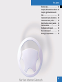
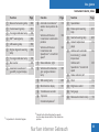
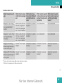
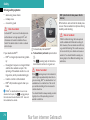
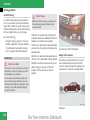
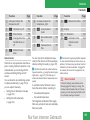
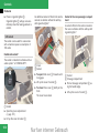
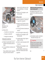
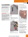
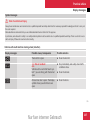
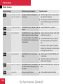
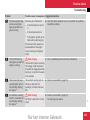
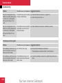
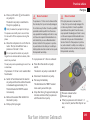
Symbols
*
Optional equipment
G
H
Warning
Environmental note
!
Possible vehicle damage
i
E
Tip
Instruction
ee
Continuation symbol
( e page) Page reference
Display
Display in the multi-function
display
Nur fuer internen Gebrauch
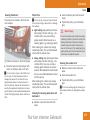
Thank you for choosing MercedesBenz.
Before you drive off, familiarise yourself
with your Mercedes-Benz and read the
Owner's Manual. This will help you to obtain the maximum pleasure from your vehicle and to avoid endangering yourself
and others.
The technical documentation team at
DaimlerChrysler AG wishes you safe and
pleasant motoring.
i You can also get to know the major features of your C-Class in the interactive Owner's
Manual on the Internet at:
www.mercedes‑benz.de/betriebsanleitung
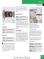
Items of optional equipment are marked
with an asterisk *. The equipment in your
vehicle may vary, depending on the model,
country specifications and availability.
Mercedes-Benz is constantly updating its
vehicles to the state of the art and therefore reserves the right to introduce
changes in design, equipment and technical features at any time. You cannot,
therefore, base any claims on the data, illustrations or descriptions in this Owner's
Manual.
The Owner's Manual, Brief Instructions
and the Service Booklet belong with the
vehicle. You should always keep them in
the vehicle and pass them on to the new
owner if you sell the vehicle.
Please consult a Mercedes-Benz Service
Centre if you have any questions.
Nur fuer internen Gebrauch
Contents
Index . . . . . . . . . . . . . . . . . . . . . . . . . . . 3
Introduction . . . . . . . . . . . . . . . . . . . . 17
At a glance . . . . . . . . . . . . . . . . . . . . . 21
Safety . . . . . . . . . . . . . . . . . . . . . . . . . 45
Controls . . . . . . . . . . . . . . . . . . . . . . . 75
Operation . . . . . . . . . . . . . . . . . . . . . 191
Practical advice . . . . . . . . . . . . . . . . 221
Technical data . . . . . . . . . . . . . . . . . 311
Nur fuer internen Gebrauch
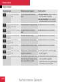
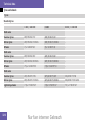
Index
7
7G‑TRONIC . . . . . . . . . . . . . . . . . . . . . 114
A
ABS . . . . . . . . . . . . . . . . . . . . . . . . . . . . 68
Display message . . . . . . . . . . . . . . 246
Display message (luxury multifunction steering wheel) . . . . . . . . 246
Display message (multi-function
steering wheel) . . . . . . . . . . 226, 228
Warning lamp . . . . . . . . . . . . . . . . 259
Acceleration
Technical data . . . . . . . . . . . . . . . . 319
Accident
Notes . . . . . . . . . . . . . . . . . . . . . . 267
Active Light System . . . . . . . . . . . . . 102
Adaptive brake lamps . . . . . . . . . . . . 68
Additional speedometer
Activating/deactivating (onboard computer, luxury multifunction steering wheel) . . . . . . . . 136
Additional turn signal (exterior
mirrors) . . . . . . . . . . . . . . . . . . . . . . . 285
ADVANCED AGILITY package
with sports mode . . . . . . . . . . . . . . . 147
ADVANCED AGILITY package
with sporty driving mode
Indicator lamp . . . . . . . . . . . . . . . . 257
Air distribution
Setting (Thermatic) . . . . . . . . . . . . 156
Setting (Thermotronic) . . . . . . . . . 165
Air filter
Display message (luxury multifunction steering wheel) . . . . . . . . 253
Display message (multi-function
steering wheel) . . . . . . . . . . . . . . . 243
Airbag . . . . . . . . . . . . . . . . . . . . . . . . . . 47
Activation . . . . . . . . . . . . . . . . . . . . 49
Control unit . . . . . . . . . . . . . . . . . . . 49
Driver's . . . . . . . . . . . . . . . . . . . . . . 52
Driver's knee airbag . . . . . . . . . . . . 53
Front . . . . . . . . . . . . . . . . . . . . . . . . 52
Front passenger . . . . . . . . . . . . . . . 52
How the airbags work . . . . . . . . . . . 52
PASSENGER AIRBAG OFF warning lamp . . . . . . . . . . . . . . . . . . . . 258
Sidebags . . . . . . . . . . . . . . . . . . . . . 53
System . . . . . . . . . . . . . . . . . . . . . . 50
Windowbags . . . . . . . . . . . . . . . . . . 54
Air-conditioning system
see Thermatic, Thermotronic
Airflow
Setting (Thermatic) . . . . . . . . . . . . 157
Setting (Thermotronic) . . . . . . . . . 165
Air-recirculation mode
Thermatic . . . . . . . . . . . . . . . . . . . 158
Thermotronic . . . . . . . . . . . . . . . . 167
Antifreeze concentration . . . . . . . . . 333
Anti-lock braking system
see ABS
Anti-theft alarm system
see ATA
Anti-theft systems . . . . . . . . . . . . . . . 71
Ashtray . . . . . . . . . . . . . . . . . . . . . . . 185
ASSYST PLUS . . . . . . . . . . . . . . . . . . 215
ATA . . . . . . . . . . . . . . . . . . . . . . . . . . . . 71
Switching off the alarm . . . . . 71, 266
Audible warning signal . . . . . . . . . . . 266
Audio
On-board computer (luxury multi-function steering wheel) . . . . . . 132
AUTO lights
Display message (luxury multifunction steering wheel) . . . . . . . . 250
Display message (multi-function
steering wheel) . . . . . . . . . . . . . . . 240
Automatic car wash . . . . . . . . . . . . . 217
Automatic transmission
Changing gear yourself . . . . . . . . . 113
Driving tips . . . . . . . . . . . . . . . . . . 115
Emergency running mode . . . . . . . 270
Malfunction . . . . . . . . . . . . . . . . . . 270
Manoeuvring . . . . . . . . . . . . . . . . . 116
Oil level . . . . . . . . . . . . . . . . . . . . . 198
One-touch gearshifting . . . . . . . . . 113
Program selector button . . . . . . . . 115
Releasing the parking lock manually . . . . . . . . . . . . . . . . . . . . . . . . 281
Nur fuer internen Gebrauch
3
Index
Selector lever positions . . . . . . . . 112
Shift ranges . . . . . . . . . . . . . . . . . . 114
Trailer towing . . . . . . . . . . . . . . . . 116
Working on the vehicle . . . . . . . . . 116
Axle load, maximum permissible . . 325
B
Ball coupling
Folding in . . . . . . . . . . . . . . . . . . . 213
Folding out . . . . . . . . . . . . . . . . . . 211
BAS . . . . . . . . . . . . . . . . . . . . . . . . . . . . 68
Battery
Changing (key) . . . . . . . . . . . . . . . 283
Charging . . . . . . . . . . . . . . . . . . . . 302
Check lamp (key) . . . . . . . . . . . . . . 77
Check lamp (KEYLESS GO key) . . . . 79
Checking (key) . . . . . . . . . . . . . . . . 77
Disconnecting . . . . . . . . . . . . . . . . 302
Display message (luxury multifunction steering wheel) . . . 247, 254
Display message (multi-function
steering wheel) . . . . . . . . . . 238, 243
Maintenance (vehicle) . . . . . . . . . . 301
Reconnecting . . . . . . . . . . . . . . . . 303
Removing/fitting . . . . . . . . . . . . . . 302
Vehicle battery . . . . . . . . . . . . . . . 301
Belt force limiters
Activation . . . . . . . . . . . . . . . . . . . . 49
Belt height adjustment . . . . . . . . . . . 96
4
Belt tensioners
Activation . . . . . . . . . . . . . . . . . . . . 49
Belt warning . . . . . . . . . . . . . . . . . . . . 96
Bio-diesel . . . . . . . . . . . . . . . . . . . . . . 194
Bi-xenon bulb . . . . . . . . . . . . . . . . . . 287
Bonnet
Display message (luxury multifunction steering wheel) . . . . . . . . 245
Display message (multi-function
steering wheel) . . . . . . . . . . . . . . . 237
Opening/closing . . . . . . . . . . . . . . 195
Bonnet release lever
Release lever . . . . . . . . . . . . . . . . . 196
Boot
Emergency unlocking . . . . . . . . . . 280
Opening (automatically) . . . . . . . . . 81
Opening/closing (manually) . . . . . . 80
Boot lid
Display message (luxury multifunction steering wheel) . . . . . . . . 245
Display message (multi-function
steering wheel) . . . . . . . . . . . . . . . 237
Brake
Warning lamp . . . . . . . . . . . . . . . . 261
Brake Assist
see BAS
Brake fluid . . . . . . . . . . . . . . . . . . . . . 333
Display message (luxury multifunction steering wheel) . . . . . . . . 247
Display message (multi-function
steering wheel) . . . . . . . . . . . . . . . 228
Brake lamp
Display message (multi-function
steering wheel) . . . . . . . . . . . . . . . 241
Brake lamps . . . . . . . . . . . . . . . . . . . 285
Adaptive . . . . . . . . . . . . . . . . . . . . . 68
Display message (luxury multifunction steering wheel) . . . . . . . . 251
Brake system
Parking brake . . . . . . . . . . . . . . . . 111
Brakes
Display message (luxury multifunction steering wheel) . . . . . . . . 247
Display message (multi-function
steering wheel) . . . . . . . . . . . . . . . 238
Bulbs
Changing the front . . . . . . . 284, 286
Changing the rear . . . . . . . . 284, 289
Front . . . . . . . . . . . . . . . . . . . 284- 285
Rear . . . . . . . . . . . . . . . . . . . . 284- 285
C
Care . . . . . . . . . . . . . . . . . . . . . . . . . . 217
Automatic car wash . . . . . . . . . . . 217
Headlamps . . . . . . . . . . . . . . . . . . 218
High-pressure cleaners . . . . . . . . . 218
Nur fuer internen Gebrauch
Index
Parktronic . . . . . . . . . . . . . . . . . . . 219
Plastic trim . . . . . . . . . . . . . . . . . . 219
Rear window . . . . . . . . . . . . . . . . . 218
Side windows . . . . . . . . . . . . . . . . 218
CD player/CD changer
Operation (on-board computer,
luxury multi-function steering
wheel) . . . . . . . . . . . . . . . . . . . . . . 132
Central locking
Automatic (on-board computer,
luxury multi-function steering
wheel) . . . . . . . . . . . . . . . . . . . . . . 139
KEYLESS GO . . . . . . . . . . . . . . . 78- 79
Central locking/unlocking button . . 80
Central unlocking
Key . . . . . . . . . . . . . . . . . . . . . . . . . 76
KEYLESS GO . . . . . . . . . . . . . . . 78- 79
Centre console
Lower section . . . . . . . . . . . . . . . . . 39
Upper section . . . . . . . . . . . . . . . . . 38
Changing a wheel
see Flat tyre
Child seat
Automatic recognition . . . . . . . . . . . 63
Automatic recognition (malfunction) . . . . . . . . . . . . . . . . . . . . . . . . 258
Display message (luxury multifunction steering wheel) . . . . . . . . 236
Display message (multi-function
steering wheel) . . . . . . . . . . . . . . . 233
ISOFIX . . . . . . . . . . . . . . . . . . . . . . . 64
Recommendations . . . . . . . . . . . . . 61
Suitable positions . . . . . . . . . . . . . . 59
Child-proof locks
Rear doors . . . . . . . . . . . . . . . . . . . . 66
Side windows (rear) . . . . . . . . . . . . 67
Children
In the vehicle . . . . . . . . . . . . . . . . . . 56
Restraint systems . . . . . . . . . . . . . . 56
Cigarette lighter . . . . . . . . . . . . . . . . 185
COC documents (EC CERTIFICATE OF CONFORMITY) . . . . . . . . . . 328
Cockpit
Overview . . . . . . . . . . . . . . 16, 24, 26
Collapsible wheel
Technical data . . . . . . . . . . . . . . . . 323
Combination switch . . . . . . . . . . . . . . 99
Constant headlamp mode
see Daytime driving lamps
Convenience closing . . . . . . . . . . . . 107
Convenience opening/closing
feature
Air-recirculation mode (Thermatic) 159
Air-recirculation mode
(Thermotronic) . . . . . . . . . . . . . . . 167
Coolant . . . . . . . . . . . . . . . . . . . . . . . . 198
Checking the level . . . . . . . . . . . . . 198
Display message (luxury multifunction steering wheel) . . . . . . . . 248
Display message (multi-function
steering wheel) . . . . . . . . . . 230, 238
Mixture ratio . . . . . . . . . . . . . . . . . 332
Temperature gauge . . . . . . . . . . . . 119
Warning lamp . . . . . . . . . . . . . . . . 261
Cooling with air dehumidification
Thermatic . . . . . . . . . . . . . . . . . . . 160
Thermotronic . . . . . . . . . . . . . . . . 168
Cornering lamps . . . . . . . . . . . . 101- 102
Cornering lights
Display message (luxury multifunction steering wheel) . . . . . . . . 249
Display message (multi-function
steering wheel) . . . . . . . . . . . . . . . 239
Cruise control . . . . . . . . . . . . . . . . . . 140
Display message (luxury multifunction steering wheel) . . . . . . . . 236
Display message (multi-function
steering wheel) . . . . . . . . . . . . . . . 233
Cup holder . . . . . . . . . . . . . . . . . . . . . 177
D
Date
Entering (on-board computer,
multi-function steering wheel) . . . 124
Setting (on-board computer,
luxury multi-function steering
wheel) . . . . . . . . . . . . . . . . . . . . . . 137
Nur fuer internen Gebrauch
5
Index
Daytime driving lamps
On-board computer (luxury multi-function steering wheel) . . . . . . 138
Daytime driving lights . . . . . . . . . . . . 98
Display message (luxury multifunction steering wheel) . . . . . . . . 253
Display message (multi-function
steering wheel) . . . . . . . . . . . . . . . 243
Demisting
Thermatic . . . . . . . . . . . . . . . . . . . 157
Thermotronic . . . . . . . . . . . . . . . . 165
Diesel
Consumption . . . . . . . . . . . . . . . . . 328
Low outside temperatures . . . . . . 195
Diesel engine
Winter driving . . . . . . . . . . . . . . . . 195
Digital speedometer . . . . . . . . . . . . . 130
Dipped-beam headlamps . . . . . 98, 285
Changing the bulbs . . . . . . . . . . . . 286
Display message (luxury multifunction steering wheel) . . . . . . . . 250
Display message (multi-function
steering wheel) . . . . . . . . . . . . . . . 239
Symmetrical . . . . . . . . . . . . . . . . . 210
Display message . . . . . . . . . . . . . . . . 224
Door
Automatic locking . . . . . . . . . . . . . . 79
Display message (luxury multifunction steering wheel) . . . 245, 255
6
Display message (multi-function
steering wheel) . . . . . . . . . . 232, 237
Opening (from the inside) . . . . . . . . 79
Door control panel
Overview . . . . . . . . . . . . . . . . . . . . . 41
Drinks holder
see Cup holder
Driver's airbag . . . . . . . . . . . . . . . . . . 52
Driver's door
Unlocking (KEYLESS GO) . . . . . . . . 79
Driver's knee airbag . . . . . . . . . . . . . . 53
Driving abroad . . . . . . . . . . . . . . . . . 210
Driving safety system . . . . . . . . . . . . 67
ABS . . . . . . . . . . . . . . . . . . . . . . . . . 68
Adaptive brake lamps . . . . . . . . . . . 68
BAS . . . . . . . . . . . . . . . . . . . . . . . . . 68
EBV . . . . . . . . . . . . . . . . . . . . . . . . . 70
ESP . . . . . . . . . . . . . . . . . . . . . . . . . 69
Driving system . . . . . . . . . . . . . . . . . 140
ADVANCED AGILITY package
with sports mode . . . . . . . . . . . . . 147
Cruise control . . . . . . . . . . . . . . . . 140
Hill start assist . . . . . . . . . . . . . . . 146
Parktronic . . . . . . . . . . . . . . . . . . . 148
Speedtronic . . . . . . . . . . . . . . . . . . 143
Driving tip
Braking . . . . . . . . . . . . . . . . . . . . . 207
Driving abroad . . . . . . . . . . . . . . . . 210
Driving on wet roads . . . . . . . . . . . 209
Fording . . . . . . . . . . . . . . . . . . . . . 209
Trailer towing . . . . . . . . . . . . . . . .
Winter . . . . . . . . . . . . . . . . . . . . . .
Driving tips
Automatic transmission . . . . . . . .
DVD Audio/Video
Operation (on-board computer,
luxury multi-function steering
wheel) . . . . . . . . . . . . . . . . . . . . . .
212
207
115
132
E
e mark . . . . . . . . . . . . . . . . . . . . . . . . 314
Easy-entry feature . . . . . . . . . . . . . . . 89
Easy-entry/exit
On-board computer (luxury multi-function steering wheel) . . . . . . 139
Easy-exit feature . . . . . . . . . . . . . . . . . 89
EBV . . . . . . . . . . . . . . . . . . . . . . . . . . . . 70
Display message (luxury multifunction steering wheel) . . . . . . . . 248
Display message (multi-function
steering wheel) . . . . . . . . . . . . . . . 228
Electrical/electronic equipment
Retrofitting . . . . . . . . . . . . . . . . . . 314
Electronic brake-power distribution
see EBV
Electronic Stability Program
see ESP
Electronic Traction Support
see ETS
Nur fuer internen Gebrauch
Index
Emergency engine starting . . . . . . . 306
Emergency key element
Lost . . . . . . . . . . . . . . . . . . . . . . . . 276
Emergency locking
Vehicle . . . . . . . . . . . . . . . . . . . . . 280
Emergency release
Fuel filler flap . . . . . . . . . . . . . . . . 281
Emergency running mode
Automatic transmission . . . . . . . . 270
Emergency unlocking
Boot . . . . . . . . . . . . . . . . . . . . . . . 280
Vehicle . . . . . . . . . . . . . . . . . . . . . 279
Engine
Running irregularly . . . . . . . . . . . . 269
Starting problems . . . . . . . . . . . . . 269
Starting with KEYLESS GO . . . . . . 109
Starting with the key . . . . . . . . . . . 108
Stopping with KEYLESS GO . . . . . 111
Stopping with the key . . . . . . . . . . 111
Technical data . . . . . . . . . . . . . . . . 317
Engine compartment
Cleaning . . . . . . . . . . . . . . . . . . . . 218
Engine diagnostic warning lamp . . . 262
Engine electronics . . . . . . . . . . . . . . 314
Malfunction . . . . . . . . . . . . . . . . . . 269
Engine number . . . . . . . . . . . . . . . . . 316
Engine oil
Checking the oil level (automatic transmission) . . . . . . . . . . . 198
Checking the oil level (dipstick) . . 197
Consumption . . . . . . . . . . . . . . . . . 197
Display message (luxury multifunction steering wheel) . . . . . . . . 254
Display message (multi-function
steering wheel) . . . . . . . . . . . . . . . 243
Filler neck . . . . . . . . . . . . . . . . . . . 198
Filling capacity . . . . . . . . . . . . . . . 330
Topping up . . . . . . . . . . . . . . . . . . 198
ESP . . . . . . . . . . . . . . . . . . . . . . . . . . . . 69
Activating/deactivating . . . . . . . . . 69
Display message (luxury multifunction steering wheel) . . . 234, 246
Display message (multi-function
steering wheel) . . . . . . . . . . 226, 228
Trailer stabilising . . . . . . . . . . . . . . . 69
Warning lamp . . . . . . . . . . . . 69, 260
ETS . . . . . . . . . . . . . . . . . . . . . . . . . . . . 69
Exterior lighting
Dipped-beam headlamps . . . . . . . 285
Licence plate lighting . . . . . . . . . . 285
Main-beam headlamps . . . . . . . . . 285
Parking lamps . . . . . . . . . . . . . . . . 285
Turn signals . . . . . . . . . . . . . . . . . . 285
Exterior mirror parking position
Storing . . . . . . . . . . . . . . . . . . . 92- 93
Exterior mirrors
Additional turn signals . . . . . . . . . 285
Adjusting . . . . . . . . . . . . . . . . . . . . . 90
Anti-dazzle mode (automatic) . . . . . 91
Folding in (on-board computer,
luxury multi-function steering
wheel) . . . . . . . . . . . . . . . . . . . . . . 140
Folding in/out (automatically) . . . . 91
Folding in/out (electrically) . . . . . . . 91
Malfunction . . . . . . . . . . . . . . . . . . 275
Parking position . . . . . . . . . . . . 92- 93
Resetting . . . . . . . . . . . . . . . . . . . . . 91
Storing settings . . . . . . . . . . . . . . . . 93
Exterior view
Overview . . . . . . . . . . . . . . . . . . . . . 22
F
Fire extinguisher . . . . . . . . . . . . . . . . 222
First-aid kit . . . . . . . . . . . . . . . . . . . . 222
Flat tyre
MOExtended run-flat system . . . . 300
Preparing the vehicle . . . . . . . . . . 291
TIREFIT kit . . . . . . . . . . . . . . . . . . . 291
Floormat . . . . . . . . . . . . . . . . . . . . . . 189
Fog lamps (extended range) . . . . . . 102
Fording . . . . . . . . . . . . . . . . . . . . . . . . 209
Frequencies
Telephone . . . . . . . . . . . . . . . . . . . 315
Front airbag . . . . . . . . . . . . . . . . . . . . . 52
Front bulbs . . . . . . . . . . . . . . . . 284- 285
Front foglamp
Display message (multi-function
steering wheel) . . . . . . . . . . . . . . . 242
Nur fuer internen Gebrauch
7
Index
Front foglamps . . . . . . . . . . . . . 99, 285
Display message (luxury multifunction steering wheel) . . . . . . . . 252
Front-passenger airbag . . . . . . . . . . . 52
Fuel . . . . . . . . . . . . . . . . . . . . . . . . . . 328
Diesel . . . . . . . . . . . . . . . . . . . . . . 194
Display message (luxury multifunction steering wheel) . . . . . . . . 248
Loss . . . . . . . . . . . . . . . . . . . . . . . 268
Petrol . . . . . . . . . . . . . . . . . . . . . . 193
Vegetable oil methyl ester . . . . . . 194
Fuel consumption . . . . . . . . . . . 328- 329
Fuel filler flap
Emergency release . . . . . . . . . . . . 281
Fuel filter
Display message (multi-function
steering wheel) . . . . . . . . . . . . . . . 230
Fuel line
Malfunction . . . . . . . . . . . . . . . . . . 268
Fuel remaining
Calling up (on-board computer,
luxury multi-function steering
wheel) . . . . . . . . . . . . . . . . . . . . . . 129
Fuel tank
Display message (multi-function
steering wheel) . . . . . . . . . . . . . . . 245
Malfunction . . . . . . . . . . . . . . . . . . 268
Fuse allocation chart . . . . . . . . . . . . 308
8
Fuse box
Boot . . . . . . . . . . . . . . . . . . . . . . . 309
Dashboard . . . . . . . . . . . . . . . . . . . 308
Engine compartment . . . . . . . . . . . 308
Fuses . . . . . . . . . . . . . . . . . . . . . . . . . 307
G
Gearshift program
Manual . . . . . . . . . . . . . . . . . . . . . 117
Genuine Mercedes-Benz parts . . . . 313
Glove compartment . . . . . . . . . . . . . 182
Gross vehicle weight, maximum
permissible . . . . . . . . . . . . . . . . . . . . 325
H
Hazard warning lamps . . . . . . . . . . . 100
Head restraint
Adjusting (front) . . . . . . . . . . . . 84- 85
Adjusting (rear) . . . . . . . . . . . . . . . . 86
NECK-PRO . . . . . . . . . . . . . . . . . . . . 56
Removing (rear) . . . . . . . . . . . . . . . . 86
Resetting triggered head restraints . . . . . . . . . . . . . . . . . . . . . 282
Headlamp flasher . . . . . . . . . . . . . . . 100
Headlamp mode (automatic) . . . . . . . 98
Headlamp range control . . . . . . . . . 100
Headlamps
Cleaning . . . . . . . . . . . . . . . . . . . . 218
Cleaning system . . . . . . . . . . . . . . 101
Misted up . . . . . . . . . . . . . . . . . . . 272
Heating
see Thermatic, Thermotronic
High-pressure cleaners . . . . . . . . . . 218
Hill start assist . . . . . . . . . . . . . . . . . 146
I
Immobiliser . . . . . . . . . . . . . . . . . . . . . 71
Incandescent bulbs
see Bulbs
Indicator and warning lamp
Brakes (red) . . . . . . . . . . . . . . . . . . 261
Coolant . . . . . . . . . . . . . . . . . . . . . 261
Engine diagnostic . . . . . . . . . . . . . 262
ESP . . . . . . . . . . . . . . . . . . . . 69, 260
LIM . . . . . . . . . . . . . . . . . . . . . . . . 141
PASSENGER AIRBAG OFF . . . 63, 258
Reserve fuel . . . . . . . . . . . . . . . . . 265
Seat belt . . . . . . . . . . . . . . . . . . . . 263
SRS . . . . . . . . . . . . . . . . . . . . 48, 263
Indicator and warning lamps . . . . . 259
Indicator lamp
see Indicator and warning lamp
Instrument cluster . . . . . . . . . . . . . . 118
On-board computer (luxury multi-function steering wheel) . . . . . . 135
Overview (luxury multi-function
steering wheel) . . . . . . . . . . . . 30, 34
Overview (multi-function steering wheel) . . . . . . . . . . . . . . . . 28, 32
Nur fuer internen Gebrauch
Index
Selecting the language (onboard computer, luxury multifunction steering wheel) . . . . . . . . 136
Instrument lighting . . . . . . . . . . . . . 119
Intelligent Light System . . . . . . . . . . 102
Display message (luxury multifunction steering wheel) . . . . . . . . 252
Display message (multi-function
steering wheel) . . . . . . . . . . . . . . . 230
On-board computer (luxury multi-function steering wheel) . . . . . . 138
Interior lighting . . . . . . . . . . . . . . . . . 103
Automatic control . . . . . . . . . . . . . 103
Manual control . . . . . . . . . . . . . . . 103
On-board computer (luxury multi-function steering wheel) . . . . . . 138
Interior lighting delayed switchoff
On-board computer (luxury multi-function steering wheel) . . . . . . 138
Interior motion sensor . . . . . . . . . . . . 72
Intermittent wipe
Windscreen wipers . . . . . . . . . . . . 105
ISOFIX
Child seat securing system . . . . . . . 64
J
Jack . . . . . . . . . . . . . . . . . . . . . . . . . . 223
Jump-starting . . . . . . . . . . . . . . . . . . 303
Jump leads . . . . . . . . . . . . . . . . . . 303
K
Key . . . . . . . . . . . . . . . . . . . . . . . . . . . . 76
Changing the battery . . . . . . . . . . 283
Checking the battery . . . . . . . . . . . . 77
Display message (luxury multifunction steering wheel) . . . . . . . . 254
Display message (multi-function
steering wheel) . . . . . . . . . . 232, 244
Factory setting . . . . . . . . . . . . . 76- 77
Malfunction . . . . . . . . . . . . . . . . . . 275
Modifying the programming . . . . . . 76
Stopping the engine . . . . . . . . . . . 111
Key positions
Key . . . . . . . . . . . . . . . . . . . . . . . . . 82
KEYLESS GO . . . . . . . . . . . . . . . . . . 82
KEYLESS GO . . . . . . . . . . . . . . . . . . . . 77
Checking the battery . . . . . . . . . . . . 79
Display message (luxury multifunction steering wheel) . . . . . . . . 254
Display message (multi-function
steering wheel) . . . . . . . . . . 232, 243
Factory settings . . . . . . . . . . . . . . . 78
Losing the key . . . . . . . . . . . . . . . . 278
Malfunction . . . . . . . . . . . . . . . . . . 277
Modifying the programming . . . . . . 79
Starting the engine . . . . . . . . . . . . 109
Stopping the engine . . . . . . . . . . . 111
Kickdown . . . . . . . . . . . . . . . . . 115, 118
L
Lamps
see Indicator and warning lamp
Language
Selecting (on-board computer,
luxury multi-function steering
wheel) . . . . . . . . . . . . . . . . . . . . . . 136
Lashing eyelets . . . . . . . . . . . . . . . . . 179
Licence plate lamp
Display message (luxury multifunction steering wheel) . . . . . . . . 252
Display message (multi-function
steering wheel) . . . . . . . . . . . . . . . 242
Licence plate lighting . . . . . . . . . . . . 285
Light switch . . . . . . . . . . . . . . . . . . . . . 97
Lighting . . . . . . . . . . . . . . . . . . . . . . . . 97
Lights
Display message (luxury multifunction steering wheel) . . . . . . . . 253
Display message (multi-function
steering wheel) . . . . . . . . . . 230, 243
LIM indicator lamp . . . . . . . . . . . . . . 141
Load compartment load, maximum 325
Loading guidelines . . . . . . . . . . . . . . 178
Nur fuer internen Gebrauch
9
Index
Locking
Automatic . . . . . . . . . . . . . . . . . . . . 79
From the inside (central locking
button) . . . . . . . . . . . . . . . . . . . . . . 80
Luggage net
Front-passenger footwell . . . . . . . 178
Lumbar support . . . . . . . . . . . . . . . . . 87
Luxury multi-function steering
wheel . . . . . . . . . . . . . . . . . . . . . 37, 125
M
Main-beam headlamps . . . . . . . . . . . 285
Changing the bulbs . . . . . . . . 287- 288
Display message (luxury multifunction steering wheel) . . . . . . . . 252
Display message (multi-function
steering wheel) . . . . . . . . . . . . . . . 242
Switching on . . . . . . . . . . . . . . . . . . 99
Maintenance
Battery . . . . . . . . . . . . . . . . . . . . . 301
Manual gearshift program . . . . . . . . 117
Manual transmission . . . . . . . . . . . . 112
Maximum speed
Technical data . . . . . . . . . . . . . . . . 318
Memory function . . . . . . . . . . . . . . . . 93
Menu (luxury multi-function
steering wheel)
Audio . . . . . . . . . . . . . . . . . . . . . . . 132
Menu overview . . . . . . . . . . . . . . . 126
Navigation . . . . . . . . . . . . . . . . . . . 130
10
Service . . . . . . . . . . . . . . . . . . . . . 135
Telephone . . . . . . . . . . . . . . . . . . . 133
Trip computer . . . . . . . . . . . . . . . . 129
Menu (multi-function steering
wheel)
Calling up display messages . . . . . 124
Entering the time/date . . . . . . . . . 124
Menu overview . . . . . . . . . . . . . . . 121
Standard display . . . . . . . . . . . . . . 123
Trip computer . . . . . . . . . . . . . . . . 123
Menu On-board computer
(luxury multi-function steering
wheel) . . . . . . . . . . . . . . . . . . . . . . . . 135
Message
see Display message, Indicator
and warning lamp
Minispare emergency spare
wheel
Technical data . . . . . . . . . . . . . . . . 323
Mirror
see Exterior or rear-view mirror
Sun visor . . . . . . . . . . . . . . . . . . . . 184
Mobile phone . . . . . . . . . . . . . . . . . . . 187
Bracket . . . . . . . . . . . . . . . . . . . . . 187
Installation . . . . . . . . . . . . . . . . . . 314
On-board computer (luxury multi-function steering wheel) . . . . . . 133
Modifying the programming
Key . . . . . . . . . . . . . . . . . . . . . . . . . 76
KEYLESS GO key . . . . . . . . . . . . . . . 79
MOExtended run-flat system* . . . . . . . . . . . . . . . . . . . . . 202, 300
Mono function
Thermatic . . . . . . . . . . . . . . . . . . . 157
Thermotronic . . . . . . . . . . . . . . . . 165
Motorway mode . . . . . . . . . . . . . . . . 102
MP3
Operation (on-board computer,
luxury multi-function steering
wheel) . . . . . . . . . . . . . . . . . . . . . . 132
Multi-function display
Activation . . . . . . . . . . . . . . . . . . . 119
Luxury multi-function steering
wheel . . . . . . . . . . . . . . . . . . . . . . 126
Multi-function steering wheel . . . . 121
Multi-function steering
wheel . . . . . . . . . . . . . . . . . . . . . 36, 120
Multi-function steering wheel
(12-button)
see Luxury multi-function steering wheel
N
Navigation
On-board computer (luxury multi-function steering wheel) . . . . . . 130
Nur fuer internen Gebrauch
Index
NECK-PRO head restraint . . . . . . . . . 56
Resetting triggered NECK-PRO
head restraints . . . . . . . . . . . . . . . 282
O
On-board computer (luxury multi-function steering wheel) . . . . . . . 125
Audio menu . . . . . . . . . . . . . . . . . . 132
Convenience submenu . . . . . . . . . 139
Display messages . . . . . . . . . . . . . 224
Factory setting submenu . . . . . . . 140
Instrument cluster submenu . . . . . 135
Lights submenu . . . . . . . . . . . . . . . 137
Navigation menu . . . . . . . . . . . . . . 130
Operation . . . . . . . . . . . . . . . . . . . 125
Overview . . . . . . . . . . . . . . . . . . . . 126
Service menu . . . . . . . . . . . . . . . . 135
Settings menu . . . . . . . . . . . . . . . . 135
Standard display submenu . . . . . . 129
Telephone menu . . . . . . . . . . . . . . 133
Time/date submenu . . . . . . . . . . . 137
Trip computer menu . . . . . . . . . . . 129
Vehicle submenu . . . . . . . . . . . . . . 139
On-board computer (multi-function steering wheel) . . . . . . . . . . . . . 120
Calling up display messages . . . . . 124
Display messages . . . . . . . . . . . . . 224
Entering the time/date . . . . . . . . . 124
Operation . . . . . . . . . . . . . . . . . . . 121
Overview . . . . . . . . . . . . . . . . . . . . 121
Standard display menu . . . . . . . . . 123
Trip computer . . . . . . . . . . . . . . . . 123
One-touch gearshifting . . . . . . . . . . 113
Outside temperature
Display (on-board computer) . . . . . 120
Overhead control panel
Overview . . . . . . . . . . . . . . . . . . . . . 40
P
Paint code number . . . . . . . . . . . . . . 315
Panorama sliding/tilting sunroof . . 173
Rain-closing feature . . . . . . . . . . . 176
Resetting . . . . . . . . . . . . . . . . . . . . 176
Parking . . . . . . . . . . . . . . . . . . . . . . . . 110
Parking aid . . . . . . . . . . . . . . . . . . . . . 92
Parktronic . . . . . . . . . . . . . . . . . . . 148
Parking brake . . . . . . . . . . . . . . . . . . 111
Display message (luxury multifunction steering wheel) . . . . . . . . 247
Parking brakes
Display message (multi-function
steering wheel) . . . . . . . . . . . . . . . 238
Parking lamp
Display message (multi-function
steering wheel) . . . . . . . . . . . . . . . 242
Parking lamps . . . . . . . . . . . . . . . . . . 285
Changing the bulbs . . . . . . . 287, 289
Display message (luxury multifunction steering wheel) . . . . . . . . 252
Parking lock
Releasing manually (automatic
transmission) . . . . . . . . . . . . . . . . 281
Parking position
Exterior mirror . . . . . . . . . . . . . . . . . 92
Parktronic . . . . . . . . . . . . . . . . . . . . . 148
Activating/deactivating . . . . . . . . 150
Malfunction . . . . . . . . . . . . . . . . . . 271
Range of the sensors . . . . . . . . . . 148
Trailer towing . . . . . . . . . . . . . . . . 150
Warning display . . . . . . . . . . . . . . . 149
PASSENGER AIRBAG OFF warning lamp . . . . . . . . . . . . . . . . . . . 63, 258
Performance . . . . . . . . . . . . . . . . . . . 318
Permanent display
On-board computer (luxury multi-function steering wheel) . . . . . . 137
Permanent Speedtronic . . . . . . . . . . 146
Petrol
Consumption . . . . . . . . . . . . . . . . . 328
Minimum grade . . . . . . . . . . . . . . . 193
Plastic trim
Cleaning . . . . . . . . . . . . . . . . . . . . 219
Power supply (trailer) . . . . . . . . . . . 214
Power windows
see Side window
Nur fuer internen Gebrauch
11
Index
PRESAFE® . . . . . . . . . . . . . . . . . . . . . . 55
Display message (luxury multifunction steering wheel) . . . . . . . . 236
Display message (multi-function
steering wheel) . . . . . . . . . . . . . . . 232
PRESAFE® system . . . . . . . . . . . . . . . . 55
Program selector button
Automatic transmission . . . . . . . . 115
Pulling away . . . . . . . . . . . . . . . . . . . 110
R
Radio
see separate operating instructions
Selecting a station (on-board
computer, luxury multi-function
steering wheel) . . . . . . . . . . . . . . . 132
Rain closing feature
Panorama sliding/tilting sunroof . 176
Rain sensor
Windscreen wipers . . . . . . . . . . . . 105
Rain-closing feature
Sliding/tilting sunroof . . . . . . . . . . 172
Range
Calling up (on-board computer,
luxury multi-function steering
wheel) . . . . . . . . . . . . . . . . . . . . . . 129
Reading lamp . . . . . . . . . . . . . . . . . . 104
Rear bulbs . . . . . . . . . . . . . . . . . 284- 285
12
Rear foglamp . . . . . . . . . . . . . . . 99, 285
Display message (luxury multifunction steering wheel) . . . . . . . . 252
Display message (multi-function
steering wheel) . . . . . . . . . . . . . . . 242
Rear seat backrest
Display message (luxury multifunction steering wheel) . . . . . . . . 255
Display message (multi-function
steering wheel) . . . . . . . . . . . . . . . 232
Folding forwards/back . . . . . . . . . 180
Rear seat belt status indicator . . . . . 97
Rear vents
Thermotronic . . . . . . . . . . . . . . . . 168
Rear window
Cleaning . . . . . . . . . . . . . . . . . . . . 218
Rear window blind . . . . . . . . . . . . . . 184
Rear window heating . . . . . . . . . . . . 170
Rear-compartment air conditioning
Thermotronic . . . . . . . . . . . . . . . . 168
Rear-view mirror
Adjusting . . . . . . . . . . . . . . . . . . . . . 90
Anti-dazzle (manual) . . . . . . . . . . . . 90
Anti-dazzle mode (automatic) . . . . . 91
Refuelling . . . . . . . . . . . . . . . . . . . . . . 193
Vegetable oil methyl ester (VME
fuels) . . . . . . . . . . . . . . . . . . . . . . . 194
Reserve fuel . . . . . . . . . . . . . . . . . . . 328
Display message (luxury multifunction steering wheel) . . . . . . . . 256
Fuel tank . . . . . . . . . . . . . . . . . . . . 328
Warning lamp . . . . . . . . . . . . . . . . 265
Residual heat/auxiliary ventilation
Thermotronic . . . . . . . . . . . . . . . . 168
Restraint system . . . . . . . . . . . . . . . . 46
Airbags . . . . . . . . . . . . . . . . . . . . . . 47
Seat belt . . . . . . . . . . . . . . . . . . . . . 47
Warning lamp . . . . . . . . . . . . . . . . 263
Restraint systems
For children . . . . . . . . . . . . . . . . . . . 56
Rev counter . . . . . . . . . . . . . . . . . . . . 120
Reverse gear
Engaging (automatic transmission) . . . . . . . . . . . . . . . . . . . . . . . 113
Engaging (manual transmission) . . 112
Reversing lamp
Display message (luxury multifunction steering wheel) . . . . . . . . 253
Display message (multi-function
steering wheel) . . . . . . . . . . . . . . . 243
Reversing lamps . . . . . . . . . . . . . . . . 285
Roller sunblind
Opening/closing . . . . . . . . . . . . . . 173
Roof load, maximum . . . . . . . . . . . . 325
Roof rack . . . . . . . . . . . . . . . . . . . . . . 177
Nur fuer internen Gebrauch
Index
Route guidance
On-board computer (luxury multi-function steering wheel) . . . . . . 130
S
Seat
Adjusting . . . . . . . . . . . . . . . . . . 84- 85
Storing settings . . . . . . . . . . . . . . . . 93
Seat belt . . . . . . . . . . . . . . . . . . . 47, 94
Adjusting the height . . . . . . . . . . . . 96
Display message . . . . . . . . . . . . . . . 97
Warning lamp . . . . . . . . . . . . 96, 263
Seat heating . . . . . . . . . . . . . . . . . . . . 87
Securing a load . . . . . . . . . . . . . . . . . 179
Selector lever
Display message (luxury multifunction steering wheel) . . . . . . . . 235
Display message (multi-function
steering wheel) . . . . . . . . . . . . . . . 229
Positions . . . . . . . . . . . . . . . . . . . . 113
Service
Calling up the due date (onboard computer) . . . . . . . . . . . . . . 216
On-board computer (luxury multi-function steering wheel) . . . . . . 135
Service indicator . . . . . . . . . . . . . . . . 215
Service products . . . . . . . . . . . . . . . . 327
Brake fluid . . . . . . . . . . . . . . . . . . . 333
Coolant . . . . . . . . . . . . . . . . . . . . . 332
Engine oil . . . . . . . . . . . . . . . . . . . 330
Fuel tank . . . . . . . . . . . . . . . . . . . . 328
Transmission oil . . . . . . . . . . . . . . 331
Windscreen washer fluid . . . . . . . . 333
Settings
Calling up a stored setting . . . . . . . 93
Factory (key) . . . . . . . . . . . . . . . 76- 77
Factory (KEYLESS GO) . . . . . . . . . . 78
Factory (on-board computer,
luxury multi-function steering
wheel) . . . . . . . . . . . . . . . . . . . . . . 140
On-board computer (luxury multi-function steering wheel) . . . . . . 135
Shift ranges
Automatic transmission . . . . . . . . 114
Side lamps
Changing the bulbs . . . . . . . 287, 289
Side marker . . . . . . . . . . . . . . . . . . . . 285
Side window
Opening/closing . . . . . . . . . . . . . . 105
Side windows
Cleaning . . . . . . . . . . . . . . . . . . . . 218
Sidebags . . . . . . . . . . . . . . . . . . . . . . . 53
Ski rack . . . . . . . . . . . . . . . . . . . . . . . 177
Sliding/tilting sunroof . . . . . . . . . . . 171
Rain closing feature . . . . . . . . . . . 172
Resetting . . . . . . . . . . . . . . . . . . . . 173
Snow chains . . . . . . . . . . . . . . . . . . . 206
Socket
Cockpit . . . . . . . . . . . . . . . . . . . . . 186
Rear compartment . . . . . . . . . . . . 186
Spare wheel
Fitting . . . . . . . . . . . . . . . . . . . . . . 296
Storage location . . . . . . . . . . . . . . 223
Technical data . . . . . . . . . . . . . . . . 323
Speed
Technical data . . . . . . . . . . . . . . . . 318
Speed limiter
Speedtronic . . . . . . . . . . . . . . . . . . 143
Speedometer
Digital (on-board computer,
luxury multi-function steering
wheel) . . . . . . . . . . . . . . . . . . . . . . 130
Segments . . . . . . . . . . . . . . . . . . . 120
Selecting display units (onboard computer, luxury multifunction steering wheel) . . . . . . . . 136
Speedtronic . . . . . . . . . . . . . . . . . . . . 143
Display message (luxury multifunction steering wheel) . . . . . . . . 236
Display message (multi-function
steering wheel) . . . . . . . . . . . . . . . 233
Permanent . . . . . . . . . . . . . . . . . . 146
Variable . . . . . . . . . . . . . . . . . . . . . 144
SRS . . . . . . . . . . . . . . . . . . . . . . . . . . . . 48
Display message (luxury multifunction steering wheel) . . . . . . . . 255
Display message (multi-function
steering wheel) . . . . . . . . . . . . . . . 244
Warning lamp . . . . . . . . . . . . 48, 263
Nur fuer internen Gebrauch
13
Index
Standard display
On-board computer (luxury multi-function steering wheel) . . . . . . 129
On-board computer (multi-function steering wheel) . . . . . . . . . . . 123
Station
see Radio
Steering wheel
Adjusting . . . . . . . . . . . . . . . . . . . . . 88
Adjusting electrically . . . . . . . . . . . . 89
Buttons (on-board computer,
luxury multi-function steering
wheel) . . . . . . . . . . . . . . . . . . . . . . 125
Buttons (on-board computer,
multi-function steering wheel) . . . 120
Storing settings . . . . . . . . . . . . . . . . 93
Steering wheel gearshift paddles . . 116
Stowage compartment . . . . . . . . . . 181
Armrest (under) . . . . . . . . . . . . . . . 183
Centre console . . . . . . . . . . . . . . . 183
Dashboard (at the top) . . . . . . . . . 182
Glove compartment . . . . . . . . . . . 182
Rear seat armrest . . . . . . . . . . . . . 183
Stowage space
Overview . . . . . . . . . . . . . . . . . . . . . 42
Stowage well
Boot floor (underneath) . . . . . . . . . 181
14
Submenu (luxury multi-function
steering wheel)
Convenience submenu . . . . . . . . . 139
Factory setting . . . . . . . . . . . . . . . 140
Instrument cluster . . . . . . . . . . . . . 135
Lights . . . . . . . . . . . . . . . . . . . . . . 137
Standard display . . . . . . . . . . . . . . 129
Time/date . . . . . . . . . . . . . . . . . . . 137
Vehicle . . . . . . . . . . . . . . . . . . . . . 139
Summer opening . . . . . . . . . . . . . . . 107
Sun visor . . . . . . . . . . . . . . . . . . . . . . 184
Supplemental Restraint System
see SRS
Surround lighting
On-board computer (luxury multi-function steering wheel) . . . . . . 138
Switching off the alarm
ATA . . . . . . . . . . . . . . . . . . . . . . . . . 71
T
Tail lamp
Display message (multi-function
steering wheel) . . . . . . . . . . 241, 243
Tail lamps . . . . . . . . . . . . . . . . . . . . . 285
Changing . . . . . . . . . . . . . . . . . . . . 289
Display message (luxury multifunction steering wheel) . . . 251, 253
Tank capacity . . . . . . . . . . . . . . . . . . 328
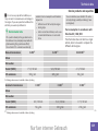
Technical data
Acceleration . . . . . . . . . . . . . . . . . 319
Engine . . . . . . . . . . . . . . . . . . . . . . 317
Speed . . . . . . . . . . . . . . . . . . . . . . 318
Trailer loads . . . . . . . . . . . . . . . . . 327
Tyres . . . . . . . . . . . . . . . . . . . . . . . 320
Vehicle dimensions . . . . . . . . . . . . 324
Vehicle weights . . . . . . . . . . . . . . . 325
Wheels . . . . . . . . . . . . . . . . . . . . . 320
Telephone
see Mobile phone
Telephone compartment . . . . . . . . . 183
Temperature
Outside temperature . . . . . . . . . . . 120
Setting (rear-compartment control panel) . . . . . . . . . . . . . . . . . . . 169
Setting (Thermatic) . . . . . . . . . . . . 156
Setting (Thermotronic) . . . . . . . . . 164
Thermatic . . . . . . . . . . . . . . . . . . . . . 154
Air distribution . . . . . . . . . . . . . . . 156
Airflow . . . . . . . . . . . . . . . . . . . . . . 157
Air-recirculation mode . . . . . . . . . 158
Cooling with air dehumidification . 160
Dashboard . . . . . . . . . . . . . . . . . . . 151
Deactivating/activating . . . . . . . . 156
Demisting . . . . . . . . . . . . . . . . . . . 157
Indicator lamp . . . . . . . . . . . . . . . . 257
Operating information . . . . . . . . . . 154
Temperature . . . . . . . . . . . . . . . . . 156
Windows misted up . . . . . . . . . . . . 158
Nur fuer internen Gebrauch
Index
Thermotronic . . . . . . . . . . . . . . . . . . 162
Activating/deactivating . . . . . . . . 164
Air distribution . . . . . . . . . . . . . . . 165
Airflow . . . . . . . . . . . . . . . . . . . . . . 165
Air-recirculation mode . . . . . . . . . 167
Cooling with air dehumidification . 168
Dashboard . . . . . . . . . . . . . . . . . . . 151
Demisting . . . . . . . . . . . . . . . . . . . 165
Indicator lamp . . . . . . . . . . . . . . . . 257
Operating information . . . . . . . . . . 162
Rear vents . . . . . . . . . . . . . . . . . . . 168
Rear-compartment air conditioning . . . . . . . . . . . . . . . . . . . . . . 168
Residual heat/auxiliary ventilation 168
Temperature . . . . . . . . . . . . . . . . . 164
Windows misted up . . . . . . . . . . . . 166
Third brake lamp . . . . . . . . . . . . . . . 285
Through-loading feature . . . . . . . . . 179
Tightening torque . . . . . . . . . . . . . . . 299
Time
Entering (on-board computer,
multi-function steering wheel) . . . 124
Setting . . . . . . . . . . . . . . . . . . . . . 119
Setting (on-board computer,
luxury multi-function steering
wheel) . . . . . . . . . . . . . . . . . . . . . . 137
TIREFIT kit
Storage location . . . . . . . . . . . . . . 223
Using . . . . . . . . . . . . . . . . . . . . . . . 291
TopTether . . . . . . . . . . . . . . . . . . . . . . 65
Tow-away protection . . . . . . . . . . . . . 72
Towing . . . . . . . . . . . . . . . . . . . . . . . . 306
Towing eye
Fitting . . . . . . . . . . . . . . . . . . . . . . 305
Removing . . . . . . . . . . . . . . . . . . . 307
Tow-starting . . . . . . . . . . . . . . . . . . . 306
Trailer
7-pin connector . . . . . . . . . . . . . . . 215
Display message (luxury multifunction steering wheel) . . . 247, 250
Display message (multi-function
steering wheel) . . . . . . . . . . 227, 240
Power supply . . . . . . . . . . . . . . . . . 214
Trailer loads
Technical data . . . . . . . . . . . . . . . . 327
Trailer tow hitch . . . . . . . . . . . . . . . . 211
Trailer towing
Automatic transmission . . . . . . . . 116
Driving tips . . . . . . . . . . . . . . . . . . 212
ESP . . . . . . . . . . . . . . . . . . . . . . . . . 69
Malfunction . . . . . . . . . . . . . . . . . . 279
Mounting dimensions . . . . . . . . . . 326
Parktronic . . . . . . . . . . . . . . . . . . . 150
Transmission oil
Filling capacity . . . . . . . . . . . . . . . 331
Transmission output (maximum)
Telephone/two-way radio . . . . . . . 314
Transport (vehicle) . . . . . . . . . . . . . . 307
Trip computer
On-board computer (luxury multi-function steering wheel) . . . . . . 129
On-board computer (multi-function steering wheel) . . . . . . . . . . . 123
Trip meter . . . . . . . . . . . . . . . . . . . . . 123
Resetting . . . . . . . . . . . . . . . 119, 123
Turn signal
Display message (luxury multifunction steering wheel) . . . . . . . . 250
Display message (multi-function
steering wheel) . . . . . . . . . . . . . . . 240
Turn signals . . . . . . . . . . . . . . . . . . . . 100
Changing the front bulbs . . 286, 288
Front . . . . . . . . . . . . . . . . . . . . . . . 285
Rear . . . . . . . . . . . . . . . . . . . . . . . . 285
Two-way radio
Installation . . . . . . . . . . . . . . . . . . 314
Tyre grip . . . . . . . . . . . . . . . . . . . . . . . 209
Tyre pressure
Display message (luxury multifunction steering wheel) . . . . . . . . 235
Display message (multi-function
steering wheel) . . . . . . . . . . . . . . . 231
Tyre pressure loss warning system 203
Tyre pressures
see Air pressure
Table . . . . . . . . . . . . . . . . . . . . . . . 319
Tyre tread . . . . . . . . . . . . . . . . . . . . . 202
Nur fuer internen Gebrauch
15
Index
Tyres
Direction of rotation . . . . . . . . . . . 202
General notes . . . . . . . . . . . . . . . . 200
Technical data . . . . . . . . . . . . . . . . 320
U
Unladen weight . . . . . . . . . . . . . . . . . 325
Unlocking
From the inside (central locking
button) . . . . . . . . . . . . . . . . . . . . . . 80
V
Variable Speedtronic . . . . . . . . . . . . 144
Vegetable oil . . . . . . . . . . . . . . . . . . . 194
Vegetable oil methyl ester . . . . . . . 194
Vehicle
Emergency unlocking . . . . . . 279- 280
Individual settings . . . . . . . . . . . . . 135
Leaving parked up . . . . . . . . . . . . . 279
Towing . . . . . . . . . . . . . . . . . . . . . . 306
Tow-starting . . . . . . . . . . . . . . . . . 306
Transporting . . . . . . . . . . . . . . . . . 307
Vehicle battery . . . . . . . . . . . . . . . . . 301
Vehicle dimensions . . . . . . . . . . . . . 324
Vehicle electronics . . . . . . . . . . . . . . 314
Vehicle identification number
(VIN) . . . . . . . . . . . . . . . . . . . . . . . . . . 316
Vehicle identification plates . . . . . . 315
Vehicle tool kit . . . . . . . . . . . . . . . . . 223
Vehicle weights . . . . . . . . . . . . . . . . 325
16
W
Warning and indicator lamp
ABS (yellow) . . . . . . . . . . . . . . . . . 259
Warning signal
Audible . . . . . . . . . . . . . . . . . . . . . 266
Warning triangle . . . . . . . . . . . . . . . . 222
Washer fluid
Display message (luxury multifunction steering wheel) . . . . . . . . 256
Display message (multi-function
steering wheel) . . . . . . . . . . . . . . . 245
Wearing seat belts . . . . . . . . . . . . . . . 94
Wheel bolts
Tightening torque . . . . . . . . . . . . . 299
Wheels
General notes . . . . . . . . . . . . . . . . 200
Interchanging . . . . . . . . . . . . . . . . 205
Technical data . . . . . . . . . . . . . . . . 320
Windowbags . . . . . . . . . . . . . . . . . . . . 54
Display message (luxury multifunction steering wheel) . . . . . . . . 256
Display message (multi-function
steering wheel) . . . . . . . . . . . . . . . 233
Windows
Cleaning . . . . . . . . . . . . . . . . . . . . 218
Cleaning the windscreen . . . . . . . . 218
Misted up (Thermatic) . . . . . . . . . . 158
Misted up (Thermotronic) . . . . . . . 166
Side windows . . . . . . . . . . . . . . . . 105
Windows misted up
Thermatic . . . . . . . . . . . . . . . . . . . 158
Thermotronic . . . . . . . . . . . . . . . . 166
Windscreen
Cleaning . . . . . . . . . . . . . . . . . . . . 218
Windscreen washer fluid . . . . . . . . . 333
Topping up . . . . . . . . . . . . . . . . . . 199
Windscreen washer fluid reservoir . . . . . . . . . . . . . . . . . . . . . . 199, 333
Windscreen washer reservoir
Capacity . . . . . . . . . . . . . . . . . . . . 333
Windscreen washer system 105,
333
Windscreen wipers . . . . . . . . . . . . . . 104
Cleaning . . . . . . . . . . . . . . . . . . . . 218
Malfunction . . . . . . . . . . . . . . . . . . 273
Winter diesel . . . . . . . . . . . . . . . . . . . 195
Winter driving . . . . . . . . . . . . . . 206- 207
Winter tyres . . . . . . . . . . . . . . . . . . . 206
Limit speed (on-board computer, luxury multi-function
steering wheel) . . . . . . . . . . . . . . . 146
Nur fuer internen Gebrauch
Introduction
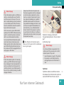
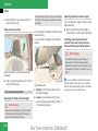
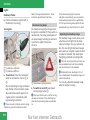
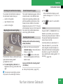
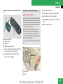
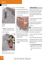
Protection of the environment
Protection of the environment
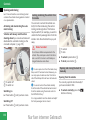
H
Remove roof racks once you no longer
need them.
I
A regularly serviced vehicle will contribute to environmental protection. You
should therefore adhere to the service
intervals.
I
Always have maintenance work carried
out at a qualified specialist workshop,
e.g. a Mercedes-Benz Service Centre.
Personal driving style
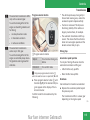
I
Do not depress the accelerator pedal
when starting the engine.
I
Do not warm up the engine with the vehicle stationary.
I
Drive carefully and maintain a safe distance from the vehicle in front.
I
Avoid frequent, sudden acceleration.
I
Change gear in good time and use each
gear only up to 2/3 of its maximum engine speed.
I
Switch off the engine in stationary traffic.
I
Environmental note
DaimlerChrysler's declared policy is one of
integrated environmental protection.
The objectives are for the natural resources
which form the basis of our existence on
this planet to be used sparingly and in a
manner which takes the requirements of
both nature and humanity into account.
You too can help to protect the environment
by operating your vehicle in an environmentally-responsible manner.
Fuel consumption and the rate of engine,
transmission, brake and tyre wear depend
on the following factors:
I
Operating conditions of your vehicle
I
Your personal driving style
You can influence both factors.
You should bear the following in mind:
Operating conditions
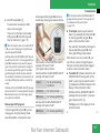
I
Avoid short trips as these increase fuel
consumption.
I
Make sure that the tyre pressures are always correct.
I
Do not carry any unnecessary weight.
I
Keep an eye on the vehicle's fuel consumption.
Returning used vehicles
Mercedes-Benz will take back your
Mercedes-Benz to dispose of it in an environmentally-responsible manner, in accordance with the European Union (EU)
End of Life Vehicles Directive.
The End of Life Vehicles Directive applies
to vehicles of up to 3.5 t gross vehicle
weight, in accordance with national regulations. For several years, Mercedes-Benz
has been meeting all the legal requirements for a design which allows for recycling and re-use. There is a network of return points and disassembly plants which
can recycle your vehicle in an environmentally-responsible manner. The options for
recycling vehicles and parts are constantly
being developed and improved. This
means that your Mercedes-Benz will also
continue to meet even the increased recycling quotas in the future in good time.
You can obtain further information from
your national Mercedes-Benz homepage or
your national hotline number.
Nur fuer internen Gebrauch
17
Introduction
Operating safety
Operating safety
G
Risk of accident and injury
All work on the vehicle and, in particular,
work relevant to safety or on safety-related
systems must be carried out at a qualified
specialist workshop. The specialist workshop must have the necessary specialist
knowledge and tools to carry out the work
required. Mercedes-Benz recommends that
you use a Mercedes-Benz Service Centre for
this purpose.
G
Risk of accident and injury
Some safety systems only function when
the engine is running. You should therefore
never switch off the engine when driving.
Otherwise the safety systems of your vehicle may no longer protect you and other
persons as intended. This would result in an
increased risk of accident and injury.
G
Risk of accident and injury
Work carried out incorrectly, or alterations
made to the vehicle, e.g. rerouting of cables
under coverings, could cause the safety systems of your vehicle to stop working properly. The safety systems would thus no lon-
18
ger protect you and other persons as intended. This would result in an increased
risk of accident and injury.
All work and alterations to the vehicle, e.g.
installations or modifications, should therefore be carried out at a qualified specialist
workshop.
G
operating safety and therefore your own
safety.
You should thus have all work and modifications to electronic components carried out
at a qualified specialist workshop.
Risk of accident
A heavy impact to the vehicle underbody,
tyres or wheels (e.g. bottoming out in rough
terrain or when driving over an obstacle at
high speed) can damage the vehicle. This also applies to vehicles which are equipped
with underbody protection.
In such cases, have your vehicle checked at
a qualified specialist workshop.
G
Risk of accident
If work on electronic equipment and its software is carried out incorrectly, this equipment could stop working. The electronic
systems are networked via interfaces. Tampering with these electronic systems could
cause malfunctions in systems which have
not been modified. Malfunctions such as
these can seriously jeopardise the vehicle's
Nur fuer internen Gebrauch
Introduction
Vehicle registration
Vehicle registration
Mercedes-Benz may ask its Service
Centres to carry out technical inspections
on certain vehicles to improve their quality
or safety.
If you did not purchase your vehicle from
an authorised specialist dealer and your
vehicle has never been inspected at a
Mercedes-Benz Service Centre, it is possible that your vehicle is not registered in
your name with Mercedes-Benz.
Mercedes-Benz can only inform you about
vehicle checks if it has your registration
data.
It is advisable to register your vehicle with
a Mercedes-Benz Service Centre.
Inform Mercedes-Benz as soon as possible
about any change in address or vehicle
ownership.
Nur fuer internen Gebrauch
19
Introduction
Correct use
Correct use
Observe the following information when
using your vehicle:
I
I
I
I
The safety notes in this manual
The “Technical data” section in this
manual
National road traffic regulations
National road traffic licensing regulations
G
Risk of injury
Various warning stickers are affixed to your
vehicle. Their purpose is to draw your attention, and the attention of others, to various
dangers. Therefore, do not remove any
warning stickers unless the sticker clearly
states that you may do so.
If you remove the warning stickers, you or
others could be injured by failing to recognise certain dangers.
20
Nur fuer internen Gebrauch
At a glance
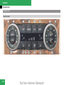
Exterior view . . . . . . . . . . . . . . . .
Cockpit, left-hand-drive vehicles
Cockpit, right-hand-drive vehicles . . . . . . . . . . . . . . . . . . . . . . . .
Instrument cluster, kilometres .
Instrument cluster, miles. . . . . .
Multi-function steering wheel . .
Centre console. . . . . . . . . . . . . . .
Overhead control panel . . . . . . .
Door control panel . . . . . . . . . . .
Stowage compartments . . . . . . .
Nur fuer internen Gebrauch
22
24
26
28
32
36
38
40
41
42
21
At a glance
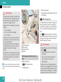
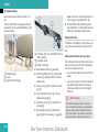
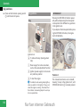
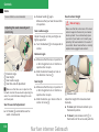
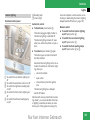
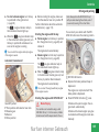
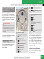
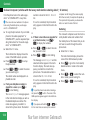
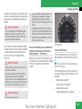
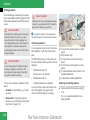
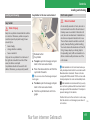
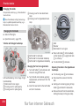
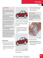
Exterior view
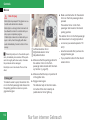
Exterior view
22
Nur fuer internen Gebrauch
At a glance
Exterior view
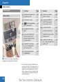
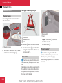
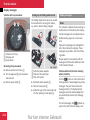
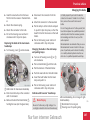
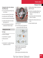
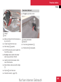
Function
1
6
Boot
Opening and closing
Function
Page
80
Spare wheel
223
Vehicle tool kit
223
Battery (depending on the
engine)
301
2
Rear lights
285
3
Rear window heating
170
4
Opening and closing the
doors
5
Demisting the windscreen
157
Cleaning the windows
218
76
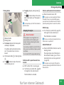
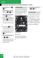
Function
Page
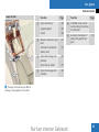
Page
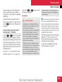
Sliding/tilting sunroof*
171
a
Front lights
285
Panorama power sliding/
tilting sunroof*
173
b
Fitting the front towing
eye
305
90
c
Tyres and wheels
200
7
Exterior mirrors
8
Windscreen wipers, operation
104
Checking the tyre pressure
203
Cleaning the wiper blades
218
296
Replacing the wiper
blades
290
Flat tyre, fitting the spare
wheel
d
Fitting the rear towing eye
305
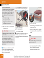
Opening the bonnet
195
e
Fuel filler flap
193
Engine oil
197
Fuel requirements
193
Coolant
198
Battery (depending on the
engine)
301
9
Nur fuer internen Gebrauch
23
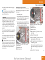
At a glance
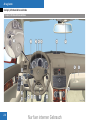
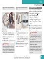
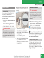
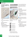
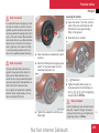
Cockpit, left-hand-drive vehicles
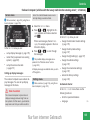
Cockpit, left-hand-drive vehicles
24
Nur fuer internen Gebrauch
At a glance
Cockpit, left-hand-drive vehicles
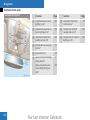
Function
1
2
Automatic transmission*:
steering wheel gearshift
paddles*
Page
116
Page
8
Opens the glove compartment
182
9
Locks/unlocks the glove
compartment
182
Cruise control lever*
Function
e
Page
Combination switch
99
• Main-beam headlamps
99
• Turn signals
100
• Windscreen wipers
104
• Cruise control*
140
a
Centre console
38
• Speedtronic*
143
b
Ignition lock
82
f
Opens the bonnet
195
KEYLESS GO button*
82
g
Parking brake
111
c
Adjusts the steering wheel
manually
88
h
Releases the parking
brake
111
d
Adjusts the steering wheel
electrically*
89
j
Light switch
97
k
Door control panel
41
l
Adjusts the headlamp
range
3
Instrument cluster
28
4
Multi-function steering
wheel
36
5
Horn
6
PARKTRONIC* warning
displays
149
Overhead control panel
40
7
Function
Nur fuer internen Gebrauch
100
25
At a glance
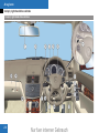
Cockpit, right-hand-drive vehicles
Cockpit, right-hand-drive vehicles
26
Nur fuer internen Gebrauch
At a glance
Cockpit, right-hand-drive vehicles
Function
1
Overhead control panel
40
2
Parktronic* warning display
149
3
Cruise control lever*
• Cruise control*
140
• Speedtronic*
143
4
Instrument cluster
32
5
Multi-function steering
wheel
36
6
Horn
7
Automatic transmission*:
steering wheel gearshift
paddles*
Function
Page
Function
Page
g
Page
8
Adjusts the headlamp
range
9
Light switch
97
• Turn signals
100
a
Door control panel
41
• Windscreen wipers
104
b
Releases the parking
brake
111
h
Parking brake
111
c
Opens the bonnet
195
j
Centre console
38
d
Ignition lock
82
k
Locks/unlocks the glove
compartment
182
KEYLESS GO button*
82
l
Adjusts the steering wheel
manually
88
Opens the glove compartment
182
e
f
Adjusts the steering wheel
electrically*
89
116
100
Nur fuer internen Gebrauch
Combination switch
99
• Main-beam headlamps
99
27
At a glance
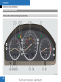
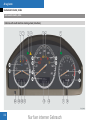
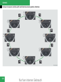
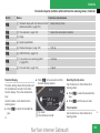
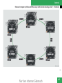
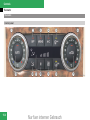
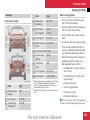
Instrument cluster, kilometres
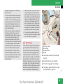
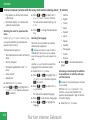
Instrument cluster, kilometres
Vehicles with multi-function steering wheel (4 buttons)
28
Nur fuer internen Gebrauch
At a glance
Instrument cluster, kilometres
Function
1
Reserve fuel warning lamp
265
2
Coolant warning lamp
261
3
Turn signal indicator lamp
100
®
Function
Page
a
Page
Automatic transmission*:
selector lever position display
113
Vehicles with manual
transmission: outside temperature
120
Vehicles with manual
transmission and
Speedtronic*: stored limit
speed1
143
4
ESP warning lamp
260
5
ABS warning lamp
259
6
Engine diagnostic warning
lamp
262
7
Turn signal indicator lamp
100
8
Rev counter
120
b
Status indicator, right
9
Automatic transmission*:
gearshift program display
115
c
Vehicles with a diesel engine: preglow indicator
lamp
109
d
SRS warning lamp
e
Multi-function display
f
Total distance recorder
g
Trip meter
Function
Page
h
Speedometer
j
Brake system warning
lamp
261
k
Seat belt warning lamp
263
l
Coolant temperature
gauge
119
m
Vehicles with automatic
transmission*: outside
temperature2
120
Vehicles with
Speedtronic*: stored limit
speed
143
n
Status indicator, left
263
o
Clock
119
121
p
Brightness control
119
q
Fuel gauge
r
Main-beam indicator lamp
119
99
1
Outside temperature
1 Only vehicles for the United Kingdom.
2 Vehicles for the United Kingdom: the speed in
km/h is always shown instead of the outside temperature.
Nur fuer internen Gebrauch
29
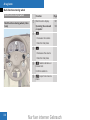
At a glance
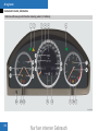
Instrument cluster, kilometres
Vehicles with luxury multi-function steering wheel (12 buttons)
30
Nur fuer internen Gebrauch
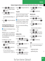
At a glance
Instrument cluster, kilometres
Function
1
Turn signal indicator lamp
®
Function
Page
100
2
ESP warning lamp
260
3
Speedometer
120
4
Segments
120
5
Multi-function display
126
6
Turn signal indicator lamp
100
7
Vehicles with a diesel engine: preglow indicator
lamp
109
8
Rev counter
120
9
SRS warning lamp
263
a
ABS warning lamp
259
b
Seat belt warning lamp
263
c
d
e
Page
Outside temperature
120
Vehicles with automatic
transmission*: additional
speedometer, if for the
Permanent display function the setting Dig. speedo (mph) is selected
136
Vehicles for the United
Kingdom with automatic
transmission*: additional
speedometer
136
Vehicles with automatic
transmission*: outside
temperature, if for the
Permanent display function the setting Dig. speedo (mph) is selected
136
Automatic transmission*:
gearshift program display
115
Function
f
Page
Vehicles with manual
transmission: additional
speedometer
136
Automatic transmission*:
selector lever position display
113
g
Clock
119
h
Total distance recorder
j
Trip meter
k
Main-beam indicator lamp
l
Coolant temperature
gauge
119
m
Coolant warning lamp
261
n
Brake system warning
lamp
261
o
Engine diagnostic warning
lamp
262
p
Brightness control
119
q
Reserve fuel warning lamp
265
r
Fuel gauge
Nur fuer internen Gebrauch
119
99
31
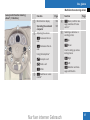
At a glance
Instrument cluster, miles
Instrument cluster, miles
Vehicles with multi-function steering wheel (4 buttons)
32
Nur fuer internen Gebrauch
At a glance
Instrument cluster, miles
Function
1
Reserve fuel warning lamp
265
2
Coolant warning lamp
261
3
Turn signal indicator lamp
100
®
Function
Page
a
Page
Automatic transmission*:
selector lever position display
113
Vehicles with manual
transmission: outside temperature
120
Vehicles with manual
transmission and
Speedtronic*: stored limit
speed3
143
4
ESP warning lamp
260
5
ABS warning lamp
259
6
Engine diagnostic warning
lamp
262
7
Turn signal indicator lamp
100
8
Rev counter
120
b
Status indicator, right
9
Automatic transmission*:
gearshift program display
115
c
Vehicles with a diesel engine: preglow indicator
lamp
109
d
SRS warning lamp
e
Multi-function display
f
Total distance recorder
g
Trip meter
Function
Page
h
Speedometer
j
Brake system warning
lamp
261
k
Seat belt warning lamp
263
l
Coolant temperature
gauge
119
m
Vehicles with automatic
transmission*: outside
temperature4
120
Vehicles with
Speedtronic*: stored limit
speed
143
n
Status indicator, left
263
o
Clock
119
121
p
Brightness control
119
q
Fuel gauge
r
Main-beam indicator lamp
119
99
3
Outside temperature
3 Only vehicles for the United Kingdom.
4 Vehicles for the United Kingdom: the speed in
km/h is always shown instead of the outside temperature.
Nur fuer internen Gebrauch
33
At a glance
Instrument cluster, miles
Vehicles with luxury multi-function steering wheel (12 buttons)
34
Nur fuer internen Gebrauch
At a glance
Instrument cluster, miles
Function
1
Turn signal indicator lamp
®
Function
Page
100
2
ESP warning lamp
260
3
Speedometer
120
4
Segments
120
5
Multi-function display
126
6
Turn signal indicator lamp
100
7
Vehicles with a diesel engine: preglow indicator
lamp
109
8
Rev counter
120
9
SRS warning lamp
263
a
ABS warning lamp
259
b
Seat belt warning lamp
263
c
d
e
Page
Outside temperature
120
Vehicles with automatic
transmission*: additional
speedometer, if for the
Permanent display function the setting Dig. speedo (mph) is selected
136
Vehicles for the United
Kingdom with automatic
transmission*: additional
speedometer
136
Vehicles with automatic
transmission*: outside
temperature, if for the
Permanent display function the setting Dig. speedo (mph) is selected
136
Automatic transmission*:
gearshift program display
115
Function
f
Page
Vehicles with manual
transmission: additional
speedometer
136
Automatic transmission*:
selector lever position display
113
g
Clock
119
h
Total distance recorder
j
Trip meter
k
Main-beam indicator lamp
l
Coolant temperature
gauge
119
m
Coolant warning lamp
261
n
Brake system warning
lamp
261
o
Engine diagnostic warning
lamp
262
p
Brightness control
119
q
Reserve fuel warning lamp
265
r
Fuel gauge
Nur fuer internen Gebrauch
119
99
35
At a glance
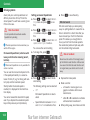
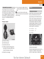
Multi-function steering wheel
Multi-function steering wheel
Function
Multi-function steering wheel (4 buttons)
1
2
Page
Multi-function display
121
Operating the on-board
computer
120
æ
• Increases the volume
• Sets the time/date
3
ç
• Decreases the volume
• Sets the time/date
4
í Selects submenu or
browse lists
Confirms selection
5
36
è Jumps from menu to
menu
Nur fuer internen Gebrauch
At a glance
Multi-function steering wheel
Luxury multi-function steering
wheel* (12 buttons)
Function
1
2
Multi-function display
126
Operating the on-board
computer
125
Adjusting the volume
Function
Page
4
L Back/confirms message/switches off voice
control*
5
Selecting a submenu or
scrolling in lists
æ Increases the volume
ç Decreases the volume
3
$ Up
% Down
Using the telephone*
Line for calling up and selecting menus
s Accepts a call
& Right
t Ends a call
( Left
F Mute
! Switches on voice
control*
Nur fuer internen Gebrauch
Page
# Selection and message confirmation
37
At a glance
Centre console
Centre console
Upper section
Function
Function
Page
100
8
Rolls the rear window
blind* up/down
184
ATA indicator lamp*
71
9
147
3
5 PASSENGER AIRBAG
OFF warning lamp5
63
Switches ADVANCED
AGILITY package with
sports mode* on/off
4
Deactivates/activates
ESP®
69
a
Controls Thermatic
154
Controls Thermotronic*
162
Switches the rear window
heating on/off
170
Switches the seat heating* on the left-hand front
seat on/off
87
1
Switches the hazard warning lamps on/off
2
5
Controls COMAND APS*
and the audio system* –
see the separate Operating Instructions
b
6
Switches the seat heating* on the right-hand
front seat on/off
87
7
Activates/deactivates
PARKTRONIC*
150
i The layout of the buttons may differ depending on the equipment in the vehicle.
5 The warning lamp also lights up briefly when you
turn the key to position 2 in the ignition lock on vehicles which do not have automatic child seat recognition on the front passenger seat*. It has no
function, however, and does not indicate that the
front-passenger seat is equipped with automatic
child seat recognition*.
38
Page
Nur fuer internen Gebrauch
At a glance
Centre console
Lower section
Function
1
2
3
4
Function
Page
Opens the ashtray*
185
Cigarette lighter*
185
Socket
186
Manual transmission: gear
lever
112
Automatic transmission*:
selector lever
112
Opens the stowage compartment
183
Opens the cup holder
177
Opens the stowage compartment
183
5
COMAND/Audio control*:
see Operating Instructions
for Head Unit
6
Automatic transmission*:
selects the gearshift program
Page
115
i The layout of the buttons may differ depending on the equipment in the vehicle.
Nur fuer internen Gebrauch
39
At a glance
Overhead control panel
Overhead control panel
40
Function
Page
Function
Page
1
Switches the rear interior
lighting on/off
103
7
Deactivates the interior
motion sensor*
72
2
Switches the automatic interior lighting on/off
103
8
Switches the left-hand
reading lamp on/off
103
3
Switches the right-hand
reading lamp on/off
103
9
Switches the front interior
lighting on/off
103
4
Deactivates tow-away protection*
72
5
Rear-view mirror
90
6
Opens/closes the sliding/
tilting sunroof*
171
Opens/closes the panorama sliding/tilting sunroof*
173
Nur fuer internen Gebrauch
At a glance
Door control panel
Door control panel
Function
Function
Page
Page
8
Opens/closes the rear
windows
105
9
Override switch for the
rear windows
67
90
a
Boot lid remote release
switch*
81
Folds the exterior mirror
in/out*
91
b
Adjusts the seat electrically*
85
5
Selects the right exterior
mirror
90
c
Locks/unlocks the door
80
6
Adjusts the exterior mirrors
90
7
Opens/closes the front
windows
105
1
Opens the door
79
2
Stores settings for the
seat, exterior mirrors and
steering wheel*
93
3
Selects the left exterior
mirror
4
Nur fuer internen Gebrauch
41
At a glance
Stowage compartments
Stowage compartments
42
Nur fuer internen Gebrauch
At a glance
Stowage compartments
Function
1
Glove compartment
2
Door stowage pocket
3
Map pocket
4
Door stowage pocket
5
Stowage well under the
boot floor
6
Open stowage space in
boot
7
Door stowage pocket
8
Map pocket
9
Door stowage pocket
a
Sun visor card clip
Page
182
Function
Page
Function
Page
b
Stowage compartment on
top of the dashboard
182
f
Stowage compartment
under the armrest
183
c
Luggage net in the frontpassenger footwell
178
g
Stowage compartment in
the rear*
183
d
Socket
186
Ashtray*
185
Ashtray*
185
h
177
Cigarette lighter*
185
Cup holder in the rear seat
armrest
Stowage compartment in
the centre console
183
j
Stowage compartment in
the rear seat armrest
183
Cup holder in the centre
console
177
181
e
184
Nur fuer internen Gebrauch
43
44
Nur fuer internen Gebrauch
Safety
Occupant safety . . . . . . . . . . . . . 46
Driving safety systems . . . . . . . . 67
Anti-theft systems. . . . . . . . . . . . 71
Nur fuer internen Gebrauch
45
Safety
Occupant safety
PRE-SAFE®* (preventive occupant safety
system) and SRS (Supplemental Restraint
System) provide additional protection and
consist of:
I
Belt tensioners
Occupant safety
Restraint systems
This section will familiarise you with the
most important features of the restraint
systems in your vehicle. In the event of an I Belt force limiters
accident, your vehicle may collide with an- I Airbags
other object, e.g. another vehicle. This
i An airbag increases the protection of vemay cause your vehicle to accelerate or
hicle occupants wearing a seat belt. However,
decelerate extremely quickly. During this
airbags are only an additional restraint system
acceleration or deceleration, the vehicle
which complements, but does not replace, the
occupants will be propelled in the opposite seat belt. All vehicle occupants must wear their
direction to the force of the impact. This
seat belt correctly at all times, even if the vemeans that the vehicle occupants risk
hicle is equipped with airbags. This is because
being injured on the vehicle interior or on
– on the one hand – airbags are not deployed
parts of the vehicle. The purpose of supin all types of accident, as in some situations
plementary restraint systems, i.e. princiairbag deployment would not increase the propally the seat belts supplemented by belt
tection afforded to vehicle occupants, provided
tensioners, belt force limiters and airbags
they are wearing their seat belt correctly.
where necessary, is to minimise this risk
On the other hand, airbag deployment only proof injury. However, seat belts and airbags
vides increased protection if the seat belt is
are generally unable to prevent injuries
worn correctly, because:
caused by objects penetrating the vehicle
I
the seat belt helps to keep the vehicle ocfrom the outside.
Seat belts and restraint systems for children are the most effective restraint systems as they effectively reduce the movement of the occupants in case of impact.
46
of the impact, and is thus better suited to
prevent injury
Thus, in accident situations where an airbag is
deployed, it only provides protection in addition
to the seat belt if the seat belt is being worn
correctly.
G
Modifications to or work performed incorrectly on restraint systems (seat belts, anchorages, belt tensioners, belt force limiters
or airbags) or their wiring, as well as work
on other networked electronic systems,
may prevent the restraint systems from
working correctly. Airbags and belt tensioners could fail, e.g. in the event of an accident, the deceleration force of which
would normally be sufficient to trigger the
systems, or could be triggered unintentionally. Never carry out any modifications on
the restraint systems. Never tamper with
electronic components and their software.
cupant in the best position in relation to the
airbag
I
Risk of injury
for example, in a head-on collision, the seat
belt can more adequately prevent the occupant from being propelled towards the force
Nur fuer internen Gebrauch
Safety
Occupant safety
Airbags
G
Risk of injury
Airbags provide additional protection; they
are not, however, a substitute for the seat
belts. To reduce the risk of serious or even
fatal injuries, make sure that all occupants –
in particular, pregnant women – wear their
seat belt correctly at all times, have adopted
a normal sitting position, and that their seat
is positioned as close to the vertical as possible.
Seat belts
The most important restraint systems in
the vehicle are the seat belts and restraint
systems for children. In the event of a collision, they are the most effective means
of restraining the movement of vehicle occupants towards the impact force and thus
reduce the danger of them hitting parts of
the vehicle interior.
G
Risk of injury
A seat belt which is not worn, which is worn
incorrectly, or which has not been engaged
in the seat belt buckle correctly, cannot perform its intended protective function. Under
certain circumstances this could cause severe or even fatal injuries. Make sure that
all vehicle occupants – in particular, pregnant women – wear their seat belt correctly
at all times.
You must make sure that the belt:
I
is routed as low as possible across your
pelvic area, i.e. across your hip joints
and not across your abdomen
I
fits closely
I
is not twisted
I
is routed across the middle of your
shoulder
I
is not routed across your neck or under
your arm
I
fits closely across your pelvic area, by
pulling upwards on the shoulder section
of the belt
Do not secure any objects with a seat belt if
the seat belt is being used by one of the vehicle's occupants.
Avoid wearing bulky clothing, e.g. a winter
coat.
Do not route the belt strap across sharpedged or fragile objects, especially if these
are on or in your clothing, e.g. spectacles,
pencils, keys, etc. The seat belt strap could
be damaged and you could be injured.
Only one person should use each seat belt
at any one time.
On no account should children travel sitting
on the lap of another occupant. It would not
be possible to restrain the child, and the
child or other vehicle occupants could be injured seriously or even fatally in the event of
abrupt braking.
Persons under 1.50 m tall or under twelve
years of age cannot wear the seat belts
properly. They therefore require additional
suitable restraint systems on appropriate
seats for protection in an accident. Always
follow the manufacturer's installation instructions when fitting a child seat.
G
Risk of injury
A seat belt can only afford its intended degree of protection if the backrest is positioned as close to the vertical as possible
and the occupant is sitting upright. Avoid
seat positions that do not allow the seat
belt to be routed correctly. You will find further information under "Seat" in the index.
Position the backrest as close to the vertical
as possible. Do not drive with the backrest
reclined too far back. Otherwise, you could
be seriously or even fatally injured in the
event of an accident or sudden braking.
Nur fuer internen Gebrauch
47
ee
Safety
Occupant safety
G
Risk of injury
The seat belt cannot function correctly if the
belt or buckle is dirty or damaged. Keep the
belt and buckle clean, otherwise the belt
tongue cannot engage correctly.
Regularly check the seat belts to make sure
that they:
I
are not damaged
I
are not routed over sharp edges
I
are not trapped
Otherwise the belt could tear in the event of
an accident. You or others could be seriously or even fatally injured.
Have seat belts which have been damaged
or subjected to heavy loads in an accident
replaced and have their anchorages
checked.
Mercedes-Benz recommends that, for safety
reasons, you only use seat belts which have
been specially approved for your vehicle by
Mercedes-Benz.
Belt force limiters
I
Airbag system with airbag control unit
and airbags
= SRS warning lamp
The SRS performs a self-test at regular intervals when the ignition is switched on
and when the engine is running. Malfunctions can therefore be detected in good
time.
The = SRS warning lamp in the instrument cluster lights up when you switch on
the ignition and goes out a few seconds
after the engine is started.
1 Belt sash guide
2 Belt tongue
3 Release button
4 Buckle
SRS (Supplemental Restraint System)
The SRS consists of:
i In many countries there are laws concern-
I
ing the use of seat belts and child restraint systems.
= SRS warning lamp
I
Belt tensioners
48
I
G
Risk of injury
A malfunction has occurred if the SRS warning lamp = :
I
does not light up when you switch on
the ignition
I
does not go out after the engine has
been running for a few seconds
I
lights up again
Some systems could be triggered unintentionally or not be triggered at all in the event
of an accident with high deceleration. Have
the SRS checked immediately at a qualified
specialist workshop which has the neces-
Nur fuer internen Gebrauch
Safety
Occupant safety
sary specialist knowledge and tools to carry
out the work required. Mercedes-Benz recommends that you use a Mercedes-Benz
Service Centre for this purpose. In particular, work relevant to safety or on safety-related systems must be carried out at a qualified specialist workshop.
Triggering of belt tensioners, belt force
limiters and airbags
In the event of a collision, the sensor in
the airbag control unit evaluates important
physical data such as duration, direction
and force of the vehicle deceleration or acceleration. Based on the evaluation of this
data and depending on the vehicle's rate
of longitudinal deceleration in a collision,
in the first stage the airbag control unit
pre-emptively triggers the belt tensioners.
milliseconds due to the control unit having
detected further deceleration.
i The front belt tensioners can only be triggered if the belt tongue is correctly engaged in
the seat belt buckle.
Criteria for triggering belt tensioners
and airbags
In the first stages of a collision, the sensor
in the airbag control unit evaluates physical data such as duration, direction and
rate of vehicle deceleration or acceleration
in order to determine whether it is necessary to trigger the belt tensioners and/or
airbags.
The belt tensioner and airbag triggering
thresholds are variable and are adapted to
the rate of deceleration of the vehicle. This
process is pre-emptive in nature as the airbag must be deployed during – and not at
the end of – the collision.
The front airbags are only deployed if there
is an even higher rate of vehicle decelera- i Airbags are not deployed in all types of action in a longitudinal direction.
cident. They are controlled by complex sensor
If your vehicle is fitted with adaptive dualstage front airbags, the front airbag is
filled with enough gas to reduce the risk of
injuries at the first deployment threshold.
The front airbag is only fully inflated if a
second threshold is reached within a few
technology and evaluation logic. This process
is pre-emptive in nature as airbag deployment
must take place during the impact and must be
adapted to provide calculated, additional protection for the vehicle occupants. Not all airbags are deployed in an accident.
The different airbag systems work independently of each other. However, the deployment
of each individual system will depend on the
type of accident determined by the control system in the initial stages of the collision (headon collision or side impact) and the severity of
the accident (in particular, the vehicle's rate of
deceleration or acceleration).
The rate of vehicle deceleration or acceleration and the direction of the force are basically determined by:
I
I
I
the distribution of forces during the collision
the collision angle
the deformation characteristics of the
vehicle
the characteristics of the object with
which the vehicle has collided, e.g. the
other vehicle
Factors which can only be seen and measured after the collision has taken place do
not play a decisive role in the deployment
of an airbag, nor do they provide an indication of it.
I
The vehicle may be considerably deformed
without an airbag being deployed if, for example, only relatively easily deformable
parts such as the bonnet or wings have
Nur fuer internen Gebrauch
49
ee
Safety
Occupant safety
been hit and the required rate of deceleration has not been reached. It is also possible that airbags may be deployed even
though the vehicle is only slightly deformed if, for example, very rigid vehicle
parts such as the longitudinal members
are hit in an accident and the rate of deceleration is sufficient.
Belt tensioners, belt force limiters
The front seat belts and the outer seat
belts in the rear are equipped with belt
tensioners and belt force limiters.
! Do not engage the seat belt tongue in the
buckle on the front-passenger seat if the seat
is not occupied. Otherwise the belt tensioner
could be activated in an emergency.
If the seat belt is also equipped with a belt
force limiter, the force exerted by the seat
belt on the seat occupant is reduced.
Belt tensioners tighten the seat belts in an
accident, pulling them close against the
body.
i Belt tensioners do not correct incorrect
seat positions or incorrectly fastened seat
belts.
I
Belt tensioners do not pull occupants back towards the backrest.
50
The front belt force limiters are synchronised with the front airbags, which spread
the forces exerted by the belt force limiters on the occupant over a greater area.
When the ignition is switched on, the belt
tensioner is triggered:
I
only when the restraint systems are operational (the = SRS warning lamp
lights up after the ignition is switched
on and goes out once the engine is running) (e page 48)
I
for each three-point seat belt in the
front of the vehicle when the belt
tongue is engaged in the buckle
I
in the event of a head-on or rear-end
collision if the vehicle decelerates or
accelerates rapidly in a longitudinal direction during the initial stages of the
collision
I
in vehicles with front-passenger seat
occupancy recognition system, only if
the front-passenger seat is occupied
and the belt tongue is engaged in the
buckle
in a serious head-on collision, i.e. if the
vehicle decelerates extremely rapidly in
a longitudinal direction during the initial
stages of the collision
If the belt tensioners are triggered, you will
hear a bang that will not damage your
hearing. A small amount of powder may also be released. The = SRS warning
lamp lights up.
G
Risk of injury
Have belt tensioners which have been triggered replaced at a qualified specialist
workshop which has the necessary specialist knowledge and tools to carry out the
work required. Mercedes-Benz recommends
that you use a Mercedes-Benz Service
Centre for this purpose. In particular, work
relevant to safety or on safety-related systems must be carried out at a qualified specialist workshop.
Comply with safety regulations when disposing of belt tensioners. Any MercedesBenz Service Centre can provide details of
these regulations.
Airbag system
G
Risk of injury
To reduce the risk of serious or even fatal
injuries in the event of an accident or similar
situation with a high rate of deceleration,
e.g. injuries caused by an airbag inflating
Nur fuer internen Gebrauch
Safety
Occupant safety
within milliseconds or sudden braking,
please observe the following points:
I
All vehicle occupants must select a seat
position that allows the seat belt to be
worn correctly and that is as far away
from the airbag as possible. The driver's
seat position must allow the vehicle to
be driven safely. The driver must maintain a distance from the pedals that allows him/her to depress these fully. The
driver's chest should be as far away
from the middle of the driver's front airbag cover as possible. The driver's arms
must be slightly bent when holding the
steering wheel.
I
Vehicle occupants should always wear
their seat belt correctly and position
their backrest as close to the vertical as
possible. The head restraint must support the back of the seat occupant's
head at about eye level.
I
Move the front-passenger seat as far
back as possible, especially if a child is
secured in a restraint system on this
seat.
I
Rearward-facing child restraint systems
must not be fitted to the front-passenger
seat unless the front-passenger front airbag has been deactivated. In MercedesBenz vehicles, the front-passenger front
I
I
I
I
airbag is deactivated if a child restraint
system with automatic child seat recognition is fitted to the front-passenger
seat of a vehicle with automatic child
seat recognition on the front-passenger
seat* and the 5 PASSENGER AIRBAG
OFF warning lamp remains lit continuously.
If either the rearward-facing child restraint system or your vehicle does not
have automatic child seat recognition on
the front-passenger seat*, children must
be secured in a child restraint system on
a suitable seat in the rear. If you secure
a forward-facing child restraint system
to the front-passenger seat, you must
move the front-passenger seat as far
back as possible.
Do not lean forwards, e.g. over the cover
of the driver's front airbag, particularly
when the vehicle is in motion.
Do not put your feet on the dashboard.
Only hold the steering wheel by the rim.
This allows the airbag to inflate fully.
You could be injured if the airbag is deployed and you are holding the inside of
the steering wheel.
Do not lean on the doors from inside the
vehicle.
Make sure that there are no people, animals or objects between the vehicle occupants and the area of deployment of
the airbag.
I
Do not place any objects between the
seat backrest and the door.
I
Do not hang any hard objects, e.g. coat
hangers, on the grab handles or coat
hooks.
It is not possible to rule out the risk of injuries caused by an airbag due to the high
speed at which the airbag is required to deploy.
I
G
Risk of injury
The airbag function is only guaranteed if
you:
I
do not cover or affix any badges or stickers to the covers of the driver's front airbag, the knee airbag underneath the
steering column, the front-passenger's
front airbag and the side trim next to the
rear bench seat backrest
I
do not modify the restraint system components, including the wiring
Your vehicle is equipped with the following
airbags:
Nur fuer internen Gebrauch
51
ee
Safety
Occupant safety
designed to reduce the force acting on the
occupant's head and chest. These airbags
are therefore depressurised after the accident.
I
Driver's front airbag, located in the
steering wheel
I
Driver's knee airbag underneath the
steering column
I
Front-passenger front airbag, located
above the glove compartment
I
Sidebags on the outer side of the front
seats
I
Rear sidebags* in the side trim next to
the backrest
Windowbags in the edge of the roof
frame
I
How the airbags work
The airbags inflate within milliseconds.
The = SRS warning lamp lights up.
i If the airbags are deployed, you will hear a
bang and a small amount of powder may also
be released. The bang will not damage your
hearing and the powder is not hazardous to
health.
Airbag deployment slows down and restricts the movement of the vehicle occupant.
When the vehicle occupant comes into
contact with the front and side airbags,
hot gas flows out of them. This feature is
52
G
Risk of injury
After an airbag has been deployed:
I
airbag parts are hot. Do not touch them,
or you could be burned
I
it must be replaced at a qualified specialist workshop which has the necessary specialist knowledge and tools to
carry out the work required. MercedesBenz recommends that you use a
Mercedes-Benz Service Centre for this
purpose. In particular, work relevant to
safety or on safety-related systems must
be carried out at a qualified specialist
workshop
G
Risk of injury
A small amount of powder is released when
an airbag deploys. This powder does not
constitute a health hazard, nor does it indicate a fire in the vehicle. The powdery dust
may cause short term breathing difficulties
to persons suffering from asthma or pulmonary problems. In order to prevent possible
breathing difficulties you should leave the
vehicle as soon as it is safe to do so, or
open a window to get fresh air.
Front airbags
The front airbags are designed to increase
protection for the driver's and front-passenger's head and chest. The driver's front
airbag and front-passenger front airbag
are deployed:
I
I
I
at the start of an accident with a high
rate of vehicle acceleration or deceleration in a longitudinal direction
if the system determines that airbag
deployment can offer additional protection to that provided by the seat belt
if the seat belt is fastened
I
independently of other airbags in the
vehicle
I
except when the vehicle overturns, unless the system detects a high rate of
vehicle deceleration in a longitudinal direction
Nur fuer internen Gebrauch
Safety
Occupant safety
The driver's knee airbag can help reduce
the risk of injury to the knees and lower
legs.
from a Mercedes-Benz Service Centre, for
example.
G
1 Driver's front airbag
2 Front-passenger front airbag
Driver's front airbag 1 deploys in front of
the steering wheel; front-passenger front
airbag 2 deploys in front of and above
the glove compartment.
In vehicles with automatic child seat recognition*, front-passenger front airbag 2
is only deployed if the 5 PASSENGER
AIRBAG OFF warning lamp in the centre
console is not lit (e page 63). This means
that no child restraint system with automatic child seat recognition* has been detected.
Driver's knee airbag
i The driver's knee airbag is only available
for certain countries.
1 Driver's knee airbag
Driver's knee airbag 1 is always deployed
along with the driver's front airbag and inflates underneath the steering column.
Sidebags
G
Risk of injury
For safety reasons, Mercedes-Benz recommends that you only use seat covers that
have been tested for use in Mercedes-Benz
vehicles and which are fitted with a special
tear seam for sidebags. Otherwise, a sidebag may not inflate correctly and fail to provide the intended protection in the event of
an accident. You can obtain these covers
Risk of injury
To reduce the risk of injury when a sidebag
is deployed, you should make sure that:
I
there are no other persons, animals or
objects between the vehicle occupants
and the deployment range of the sidebags
I
no accessories, e.g. drinks can holders,
are attached to the doors
I
only light clothing is hung on the coat
hooks in the vehicle
I
there are no heavy or sharp objects in
the pockets of items of clothing
G
Risk of injury
Observe the following points to reduce the
risk of serious or even fatal injuries if the
sidebag is deployed:
I
Vehicle occupants – in particular, children – must not lean their head on the
Nur fuer internen Gebrauch
ee
53
Safety
Occupant safety
I
I
area of the window in which a sidebag is
deployed.
Vehicle occupants must always wear
their seat belt correctly and position
their backrest as close to the vertical as
possible.
Always secure children less than 1.50 m
tall or under 12 years of age in suitable
child restraint systems.
G
the vehicle occupants on the side of the
vehicle on which the impact occurs.
I
independently of the use of the seat
belt
You can recognise the places where sidebags are fitted in your vehicle by the AIRBAG symbol.
I
independently of the front airbags
independently of the belt tensioners
i You can find further information about how
the airbags work on (e page 52).
You can find further information about the triggering of belt tensioners and belt force limiters
on (e page 49).
Risk of injury
Windowbags
The airbag control sensors are located in
the doors. Do not make any modifications
to the doors or door trim, such as retrofitting loudspeakers. Damage to the doors can
affect how the sidebags operate. Only have
work on the doors done at a qualified specialist workshop which has the necessary
specialist knowledge and tools to carry out
the work required. Mercedes-Benz recommends that you use a Mercedes-Benz
Service Centre for this purpose. In particular, work relevant to safety or on safety-related systems must be carried out at a qualified specialist workshop
G
1 Front sidebag
2 Rear sidebag* in the side trim next to
the backrest
The sidebags inflate next to the outer seat
cushions.
Front sidebags 1 and rear sidebags* 2
are deployed:
I
on the side on which an impact occurs
I
The purpose of sidebag deployment is to
enhance the level of protection for the
thorax (but not the head, neck or arms) of
54
I
at the start of an accident with a high
rate of lateral vehicle deceleration or
acceleration, e.g. in a side impact
Risk of injury
In order for the windowbag to provide its intended level of protection, make sure that
there are no objects between the vehicle occupants and the area of deployment of the
windowbags.
G
Risk of injury
Observe the following notes to reduce the
risk of serious or even fatal injury if the
windowbag is deployed:
I
Vehicle occupants – in particular, children – must not lean their head on the
Nur fuer internen Gebrauch
Safety
Occupant safety
I
I
area of the window in which the windowbag is deployed
Vehicle occupants must always have
their seat belts fastened correctly
Always secure children less than 1.50 m
tall or under 12 years of age in suitable
child restraint systems.
Windowbags 1 are deployed:
I
at the start of an accident with a high
rate of vehicle acceleration or deceleration in a lateral direction
I
on the side on which an impact occurs
independently of the front airbags
I
I
The purpose of the windowbags is to enhance the level of protection for the head
(but not chest or arms) of the vehicle occupants on the side of the vehicle on
which the impact occurs. The windowbags
are integrated into the side of the roof
frame and deploy in the area extending
from the front door (A-pillar) to the rear
door (C-pillar).
1 Windowbag
If you are driving faster than approximately
35 km/h, PRESAFE® takes the following
measures in the aforementioned situations:
I
It tensions the front seat belts.
I
regardless of whether the frontpassenger seat is occupied
i You can find further information about how
the airbags work on (e page 52).
You can find further information about the triggering of belt tensioners and belt force limiters
on (e page 49).
PRE-SAFE® system*
The PRESAFE® system takes pre-emptive
measures to protect you in certain hazardous situations. PRESAFE® intervenes in
the event of:
I
emergency braking situations, e.g. if
BAS Brake Assist intervenes
I
critical situations involving driving dynamics, e.g. if the vehicle oversteers or
understeers due to physical limits
being exceeded
On vehicles with a memory package*:
it adjusts the seat to a better position
if the fully electrically adjustable frontpassenger seat is in an unfavourable
position.
If the vehicle skids, it closes the sliding/tilting sunroof*/panorama sliding/
tilting sunroof* and the side windows,
leaving only a small slit.
If the hazardous situation passes without
resulting in an accident, PRESAFE® releases the belt pretensioning. You can
then adjust the fully electrically adjustable
front-passenger seat*, the side windows
and the sliding/tilting sunroof* again.
I
If the seat belts are not released:
E Move the backrest or the seat back
slightly until the belt tension is reduced.
The locking mechanism releases.
! Make sure that there are no objects in the
footwell or behind the seats when adjusting the
Nur fuer internen Gebrauch
55
ee
Safety
Occupant safety
seats. You could otherwise damage the seats
and the objects.
NECK-PRO head restraint
NECK-PRO head restraints are designed to
increase protection to the driver's and
front-passenger's head and neck. To this
end, the head restraints on the driver's
and front-passenger seats are moved forwards and upwards in the event of a rearend collision in the direction of travel. This
provides better head support.
G
Risk of injury
Head restraint covers prevent the NECKPRO head restraints from triggering correctly. Consequently, the NECK-PRO head
restraints cannot provide the intended level
of protection. Do not use head restraint covers.
If the NECK-PRO head restraints are triggered in an accident, you must reset the
head restraints on the driver's and frontpassenger seats (e page 282). Head restraints that have been triggered are tilted
forwards.
56
Children in the vehicle
If a child is travelling in the vehicle, secure
the child, preferably on a suitable seat in
the rear, with a child restraint system suitable for the age and size of the child and
recommended for Mercedes-Benz vehicles. Make sure that the child is strapped in throughout the trip.
You can obtain information about the correct child restraint system from any
Mercedes-Benz Service Centre.
i It is advisable to use Mercedes-Benz care
products to clean child restraint systems. You
can obtain information about this from any
Mercedes-Benz Service Centre.
G
Risk of injury
Do not leave children unsupervised in the
vehicle, even if they are secured in a child
restraint system. The children could:
I
injure themselves on parts of the vehicle
I
be severely or even fatally injured by
prolonged exposure to intense heat or
cold
Do not expose the child restraint system to
direct sunlight, as this could cause, for example, metallic parts of the child restraint
system to become very hot. Touching these
parts could cause skin burns.
If the children open a door, they could:
I
injure other people in doing so
I
get out of the vehicle and thereby injure
themselves or be injured by a passing
vehicle
Do not carry heavy or hard objects inside
the vehicle unless they are secured. You will
find further information under “Loading
guidelines” in the index.
An unsecured or incorrectly positioned load
increases the risk of injury to the child in
the event of:
I
sharp braking
I
a sudden change in direction
I
an accident
Child restraint systems
Mercedes-Benz recommends that you only
use the child restraint systems listed on
(e page 61).
G
Risk of injury
To reduce the risk of serious or even fatal
injury to the child in the event of an accident, braking or sudden change in direction:
Nur fuer internen Gebrauch
Safety
Occupant safety
I
I
I
I
I
always secure children less than 1.50 m
tall and under twelve years of age in a
special child restraint system installed
on a suitable vehicle seat, as the seat
belts are not designed for passengers of
this size
do not allow children under twelve years
of age to sit on the front-passenger seat
unless they are secured in a child restraint system with automatic child seat
recognition in a vehicle which also has
automatic child seat recognition on the
front-passenger seat*
never allow children to travel sitting on
the lap of another occupant. It would not
be possible to restrain the child due to
the forces occurring in the event of an
accident, heavy braking or sudden
change in direction. They would be
thrown against parts of the vehicle interior and be seriously or even fatally injured
all vehicle occupants must always have
their seat belt fastened correctly
If you fit a child restraint system to the
front-passenger seat, you must move
the front-passenger seat as far back as
possible
G
Risk of injury
If the child restraint system is not fitted
properly to an appropriate seat, the child
cannot be secured in the event of an accident or sudden braking and may be injured
seriously or even fatally. When fitting a child
restraint system, you must observe the
manufacturer's installation instructions and
correct use of the child restraint system.
Child restraint systems should preferably be
fitted to the rear seats. The child is generally
better protected there.
Never place objects, e.g. cushions, under
the child restraint system. The entire base
of the child restraint system must always be
resting on the seat cushion.
Child restraint systems must not be used
without their original cover. Only replace
damaged covers with genuine MercedesBenz covers.
Only use child restraint systems which have
been recommended for Mercedes-Benz on
the rear seats.
Child seat on the front-passenger seat
Warning sticker on the front-passenger
sun visor
Nur fuer internen Gebrauch
ee
57
Safety
Occupant safety
Warning symbol for a rearward-facing child
restraint system
G
Risk of injury
The front-passenger front airbag is not disabled:
I
in vehicles without automatic child seat
recognition on the front-passenger seat*
I
in vehicles with automatic child seat recognition on the front-passenger seat*, if
58
a special child restraint system with automatic child seat recognition has not
been fitted to the front-passenger seat
or the 5 PASSENGER AIRBAG OFF
warning lamp is not lit
If the front-passenger front airbag is not disabled, a child secured in a child restraint
system on the front-passenger seat could
be seriously or even fatally injured by the
front-passenger front airbag deploying in
the event of an accident, especially if the
child is in the immediate vicinity of the
front-passenger front airbag when it is deployed.
To draw attention to this danger, there is an
appropriate warning sticker on the dashboard as well as on both sides of the sun visor on the front-passenger side.
If the front-passenger front airbag is not disabled, a child must never be secured on the
front-passenger seat in a rearward-facing
child restraint system. In this case, only a
rearward facing child restraint system may
be fitted to a suitable rear seat.
If you secure a child in a forward-facing
child restraint system on the front-
passenger seat and the front-passenger
front airbag is not disabled (e.g. in a vehicle
without automatic child seat recognition on
the front-passenger seat* or in a vehicle
with automatic child seat recognition on the
front-passenger seat* and if the 5
PASSENGER AIRBAG OFF warning lamp is
not lit), always position the front-passenger
seat in its rearmost position.
Information about recommended child restraint systems is available at any
Mercedes-Benz Service Centre.
Do not place any objects, e.g. a cushion,
under the child restraint system. The entire
base of the child restraint system must always be resting on the seat cushion. An incorrectly fitted child restraint system cannot
perform its intended protective function in
the event of an accident, and could even
lead to injuries.
Nur fuer internen Gebrauch
Safety
Occupant safety
Suitable vehicle seats
Weight categories and
ages
Child restraint system Child restraint syson the front-passenger tem on the left-hand
seat
and right-hand rear
seats
Child restraint system
on the centre rear seat
without through-loading feature
Child restraint system
on the centre rear seat
with through-loading
feature*
Category 0: up to 10 kg;
Up to approximately 9
months
Vehicles with automatic Universal or as recomchild seat recognition* mended
on the front-passenger
seat: as recommended6
As recommended
As recommended
Category 0+: up to 13 kg;
Up to approximately
18 months
Vehicles with automatic Universal or as recomchild seat recognition* mended
on the front-passenger
seat: as recommended6
As recommended
As recommended
Category I: 9 to 18 kg;
Universal7 or as recommended
Universal or as recommended
Universal or as recommended
Universal or as recommended
Category II/III: 15 to 36 kg; Universal7 or as recomBetween approximately 3½ mended
Universal or as recommended
Universal or as recommended
Universal or as recommended
Between approximately 8
months and 4 years
and 12 years
6 Only use child restraint systems with automatic child seat recognition.
7 Move the front-passenger seat to its rearmost position.
ee
Nur fuer internen Gebrauch
59
Safety
Occupant safety
"Universal" category child restraint systems can be recognised by their orange
approval label. The label is affixed to the
child seat and identifies the type of child
seat.
Example of an approval label on the child
restraint system
ISOFIX* child seat securing system
Weight
Carry-cot
0: up to
category
10 kg
0+: up to 13 kg
I: 9 to 18 kg
Size cate- F
gory
G
E
E
D
C
D
C
B
B1
Equipment
ISO/L2
ISO/R1
ISO/R1
ISO/R2
ISO/R3
ISO/R2
ISO/R3
ISO/F2
ISO/F2X ISO/F3
60
ISO/L1
Nur fuer internen Gebrauch
A
Safety
Occupant safety
Weight
category
Carry-cot
X8
Rear
bench
seat, left
and right
X8
0: up to
10 kg
0+: up to 13 kg
IL9
IL9
IL9
I: 9 to 18 kg
IL9
IL9
IL9
IUF10
IUF10
IUF10
8 X: this position is unsuitable.
9 IL: as recommended, see the following table of ISOFIX child seat securing systems.
10 IUF: suitable for forward-facing ISOFIX child seat securing systems that belong to the Universal category and are approved for use in this weight category.
Recommended child restraint systems
Weight categories and
ages
Manufacturer
Type
Approval number
DaimlerChrysler
order number
Automatic child
seat recognition
Category 0: up to 10 kg;
Britax-Römer
BABY SAFE
PLUS
E1 03 301146
B6 6 86 8212
Yes
B6 6 86 8213
No11
Category 0+: up to 13 kg; Britax-Römer
up to approximately
18 months
BABY SAFE
PLUS
E1 03 301146
B6 6 86 8212
Yes
B6 6 86 8213
No11
BABY SAFE ISO- E1 04 301146
FIX PLUS
B6 6 86 8224
No11
Britax-Römer
DUO PLUS
B6 6 86 8217
Yes
A000 920 10 21
No12
up to approximately 9
months
Category I: 9 to 18 kg;
between approximately 8
months and 4 years
E1 03 301133
Nur fuer internen Gebrauch
ee
61
Safety
Occupant safety
Weight categories and
ages
Manufacturer
Type
Approval number
DaimlerChrysler
order number
Automatic child
seat recognition
Category II/III: 15 to
36 kg;
Britax-Römer
KID
E1 03 301148
B6 6 86 8308
No12
B6 6 86 8309
Yes
B6 6 86 8302
No12
B6 6 86 8303
Yes
between approximately
3½ and 12 years
11 The child restraint system must not be fitted to the front-passenger seat.
12 If you are using a child restraint system without automatic child seat recognition, move the front-passenger seat to its rearmost position.
ISOFIX* child seat securing system
Weight class Weight cate- Manufacturer Type
gory
Type approval Category
number
Automatic
DaimlerChrys- child seat recler order num- ognition
ber
A
9 to 18 kg
-
-
-
-
-
-
B
9 to 18 kg
-
-
-
-
-
-
B1
9 to 18 kg
Römer
DUO PLUS
E1 03 301133 Universal
B6 6 86 8217
Yes
B6 6 86 8218
No
C
9 to 18 kg
-
-
-
-
-
-
-
-
-
-
-
-
up to 13 kg
D
9 to 18 kg
up to 13 kg
62
Nur fuer internen Gebrauch
Safety
Occupant safety
Weight class
Weight category
Manufacturer Type
Type approval Category
number
Automatic
DaimlerChrys- child seat recler order num- ognition
ber
E
up to 10 kg
-
-
-
-
-
up to 13 kg
Römer
BABY SAFE
ISOFIX PLUS
E1 04 301146 Universal
B6 6 86 8224
No
F
up to 10 kg
-
-
-
-
-
-
G
up to 10 kg
-
-
-
-
-
-
Automatic child seat recognition* on
the front-passenger seat
-
The warning lamp13 is located on the
centre console.
If your vehicle does not have automatic
child seat recognition* on the frontpassenger seat, this is indicated by a special sticker.
The sticker is affixed to the side of the
cockpit on the front-passenger side. It is
visible when you open the front-passenger
door.
13 The warning lamp lights up briefly when you turn
the key to position 2 in the ignition lock even on
vehicles which do not have automatic child seat
recognition* on the front-passenger seat. However, it has no function and does not indicate that
there is automatic child seat recognition* on the
front-passenger seat.
The automatic child seat recognition sensor system in the front-passenger seat automatically detects whether a special
Mercedes-Benz child seat with automatic
child seat recognition has been fitted. If
this is the case, the 5 PASSENGER
AIRBAG OFF warning lamp on the centre
console lights up. The front-passenger
front airbag has been disabled.
G
1 5 PASSENGER AIRBAG OFF warning lamp
Risk of injury
If 5 PASSENGER AIRBAG OFF warning
lamp does not light up when the child restraint system is fitted, the front-passenger
front airbag has not been deactivated. The
child could suffer life-threatening injuries if
Nur fuer internen Gebrauch
63
ee
Safety
Occupant safety
the front-passenger front airbag is deployed.
If the above warning lamp does not light up
when the child seat is fitted, proceed as follows:
I
Do not use a rearward-facing child restraint system on the front-passenger
seat.
I
Fit a rearward-facing child restraint system on a suitable rear seat.
or
I
Only use a forward-facing child seat on
the front-passenger seat and move the
front-passenger seat to its rearmost position.
I
Have the automatic child seat recognition checked at a qualified specialist
workshop which has the necessary specialist knowledge and tools to carry out
the work required. Mercedes-Benz recommends that you use a Mercedes-Benz
Service Centre for this purpose. In particular, work relevant to safety or on
safety-related systems must be carried
out at a qualified specialist workshop.
To ensure that the automatic child seat recognition on the front-passenger seat functions correctly, never place objects (e.g. a
cushion) under the child restraint system.
The entire base of the child restraint system
64
must always be resting on the seat cushion.
An incorrectly fitted child restraint system
cannot perform its intended protective function in the event of an accident, and could
even lead to injuries.
I
I
i The windowbag, the sidebag and the belt
tensioner on the front-passenger side are still
active even if the front-passenger front airbag
is disabled.
G
Risk of injury
Do not place items of electronic equipment
on the front-passenger seat, e.g.:
I
laptops, if switched on
I
mobile phones
I
cards with transponders, e.g. ski passes
or access passes
as the signals from electronic equipment
can cause interference in the sensor system
of the automatic child seat recognition system. This can lead to a system malfunction
and cause the 5 PASSENGER AIRBAG
OFF warning lamp:
to light up even when there is no child
seat with automatic child seat recognition fitted, meaning that the frontpassenger airbag will not be deployed in
the event of an accident
not to light up briefly when the key is
turned to position 2 in the ignition lock.
ISOFIX child seat securing system in
the rear
ISOFIX is a standardised securing system
for special child seats in the rear. There
are securing rings for two child restraint
systems on the left- and right-hand rear
seats between the seat cushions and the
backrest.
G
Risk of injury
A child restraint system secured by the ISOFIX child seat securing system does not provide sufficient protection for children weighing more than 22 kg. For this reason, do not
secure children weighing more than 22 kg
in a child restraint system secured by the
ISOFIX child seat securing system. If the
child weighs more than 22 kg, secure the
child restraint system using a lap-shoulder
belt.
Nur fuer internen Gebrauch
Safety
Occupant safety
G
Risk of injury
If the child restraint system is not fitted correctly to a suitable vehicle seat, the child
cannot be secured in the event of an accident or sudden braking and may be seriously or even fatally injured. Follow the manufacturer's installation instructions when fitting the child restraint system.
On the rear seats, only use child restraint
systems with an ISOFIX child seat securing
system* and which have been recommended for use in Mercedes-Benz vehicles.
An incorrectly fitted child restraint system
could come loose and seriously or even
fatally injure the child or other vehicle occupants. When fitting the child restraint system, make sure that it is engaged in the securing rings on both sides.
G
Risk of injury
If the child restraint system or its securing
system, e.g. ISOFIX child seat securing system, is damaged or has been subjected to a
load in an accident, the child secured in it
could be seriously or even fatally injured in
the event of an accident, braking or sudden
changes of direction.
Always have child restraint systems and
their securing systems which are damaged
or which have been subjected to a heavy
load in an accident checked and, if necessary, replaced immediately at a qualified
specialist workshop which has the necessary specialist knowledge and tools to carry
out the work required. Mercedes-Benz recommends that you use a Mercedes-Benz
Service Centre for this purpose. In particular, work relevant to safety or on safety-related systems must be carried out at a qualified specialist workshop
! When fitting the child restraint system,
make sure that the seat belt for the middle seat
does not get trapped.
Illustration showing a vehicle with
through-loading feature in the rear bench
seat*
1 Securing rings
G
Risk of injury
Do not leave children unsupervised in the
vehicle, even if they are secured in a child
restraint system. They could:
I
injure themselves on parts of the vehicle
I
be severely or even fatally injured by
prolonged exposure to intense heat or
cold
TopTether
TopTether enables an additional connection between the child restraint system secured with ISOFIX and the rear seat. It
Nur fuer internen Gebrauch
65
ee
Safety
Occupant safety
Make sure not to interfere with the correct routing of TopTether belt* 3.
helps reduce even further the risk of injury.
E
The two TopTether anchorage points are
located on the rear shelf behind the outer
head restraints.
Fit the ISOFIX child restraint system
with TopTether*. Comply with the manufacturer's installation instructions.
Child-proof locks
If children are travelling in the vehicle, you
can activate the child-proof locks for the
rear.
3 TopTether belt* for the ISOFIX child restraint system
4 TopTether hook*
5 Tether anchorage
E
1 Head restraint
2 Cover
5 TopTether anchorage
E
E
E
E
E
66
Move head restraint 1 upwards.
Guide TopTether belt* 3 under head
restraint 1 between the two head restraint rods.
Fold up cover 2 of TopTether anchorage 3.
Hook TopTether hook* 4 into TopTether anchorage 5.
Fold down cover 2 of TopTether anchorage 5.
Move head restraint 1 back down
again slightly if necessary (e page 86).
Child-proof locks for the rear doors
The child-proof locks on the rear doors enable you to secure each door individually.
If a door has been secured:
I
you will not be able to open it from the
inside
I
you can only open it from the outside if
the vehicle is unlocked. The locking
knobs are at the top on the inside of
the door.
G
Risk of injury
Activate the child-proof locks on the rear
doors and deactivate the rear-compartment
window controls when children are travelling in the vehicle. The children could otherwise open doors or windows while the ve-
Nur fuer internen Gebrauch
Safety
Driving safety systems
hicle is in motion, injuring themselves and
others.
hicle is in motion, injuring themselves and
others.
Driving safety systems
In this section, you will find information
about the following driving safety systems:
ABS (Anti-lock Braking System)
BAS (Brake Assist System)
I
I
Adaptive brake lamps
ESP® (Electronic Stability Program)
I
I
EBV (electronic brake-power distribution)
I
i In wintry road conditions, use winter tyres
1 To activate
2 To deactivate
1 Indicator lamp
2 Button
E
To activate or deactivate: press the
latch upwards 1 or downwards 2.
E
E
Check that the child-proof locks are
working properly.
Override switch for the rear windows*
G
To activate or deactivate: press button 2.
Indicator lamp 1 lights up or goes out.
If it is lit, you can no longer operate the
rear side windows using the switches
in the rear compartment.
i Even when indicator lamp 1 is lit, you can
Risk of injury
Activate the child-proof locks on the rear
doors and deactivate the rear-compartment
window controls when children are travelling in the vehicle. The children could otherwise open doors or windows while the ve-
still open the rear side windows using the
switches on the driver's door.
(M+S tyres) and snow chains if necessary. Only
this way will ABS, BAS and ESP® be fully effective.
G
Risk of accident
The risk of an accident increases if you drive
too quickly, especially when cornering, on
wet and icy roads and if you drive too close
to the vehicle in front.
The driving safety systems described in this
section are unable to reduce this risk or
override the laws of physics.
You should therefore always adapt your driving style to suit the prevailing road and
weather conditions and maintain a sufficient
distance from other road users and objects
on the road.
Nur fuer internen Gebrauch
67
ee
Safety
Driving safety systems
For full braking application:
E
ABS (Anti-lock Braking System)
ABS regulates brake pressure in such a
way that the wheels do not lock when you
brake. This allows you to continue steering
the vehicle when braking.
ABS works from a speed of about 8 km/h
upwards, regardless of road-surface conditions.
ABS works on slippery surfaces, even
when you only brake gently.
G
Risk of accident
Do not depress the brake pedal several
times in quick succession (pumping). Depress the brake firmly and evenly. Pumping
the brake pedal reduces the braking effect.
Braking
When ABS intervenes when braking, you
will feel a pulsing in the brake pedal.
If ABS intervenes:
E continue to depress the brake pedal
with force until the braking situation is
over
68
depress the brake pedal with maximum
force
G
Risk of accident
You should always adapt your driving style
to suit the prevailing road and weather conditions and maintain a sufficient distance
from other road users and objects on the
road.
If ABS is faulty, the wheels could lock when
braking. This limits the steerability of the vehicle when braking and the braking distance
may increase.
If ABS is deactivated due to a fault, then
BAS is also deactivated.
BAS (Brake Assist)
BAS operates in emergency braking situations. If you depress the brake pedal
quickly, BAS automatically boosts the
braking force and thus shortens the stopping distance.
E
Keep the brake pedal firmly depressed
until the emergency braking situation is
over.
ABS prevents the wheels from locking.
The brakes will function as usual once you
release the brake pedal. BAS is deactivated.
G
Risk of accident
If BAS has malfunctioned, the braking system remains available with full brake boosting effect. However, braking force is not automatically increased in emergency braking
situations and the stopping distance may increase.
Adaptive brake lamps
i Adaptive brake lamps are only available in
certain countries.
If you brake sharply from a speed of more
than 50 km/h or if braking is assisted by
BAS, the brake lamps flash rapidly. This
warns traffic travelling behind.
If you brake from a speed of more than
70 km/h and bring the vehicle to a halt,
the hazard warning lamps switch on automatically once the vehicle is stationary
and the brake lamps light up constantly if
you depress the brake pedal again. The
hazard warning lamps switch off automatically if you travel faster than 10 km/h.
Nur fuer internen Gebrauch
Safety
Driving safety systems
®
ESP (Electronic Stability Program)
ESP® monitors driving stability and traction, i.e. power transmission between the
tyres and the road surface.
ESP® detects when a wheel spins or the
vehicle enters a skid. ESP® stabilises the
vehicle by braking individual wheels and
limiting the engine power output, and assists you when pulling away on a wet or
slippery road surface. ESP® also stabilises
the vehicle during braking.
When ESP® intervenes, the v warning
lamp flashes in the instrument cluster.
G
Risk of accident
If the v warning lamp in the instrument
cluster flashes, proceed as follows:
I
Do not deactivate ESP® under any circumstances.
I
Only depress the accelerator pedal as
far as necessary when pulling away.
I
Adapt your driving style to suit the prevailing road and weather conditions.
The vehicle could otherwise go into a skid.
ESP® cannot reduce the risk of an accident
if you drive too fast. ESP® cannot override
the laws of physics.
! If the vehicle is to be towed with the front
or rear axle raised, the ignition must be
switched off (key in position 0 or 1 in the ignition lock). Application of the brakes by ESP®
could otherwise destroy the brake system on
the front or rear axle.
i Only use wheels with the recommended
tyre sizes. Only then will ESP® function properly.
ESP® trailer stabilising
If your trailer begins to lurch, you can only
stabilise the vehicle/trailer combination
by depressing the brake firmly.
In this situation, ESP® assists you and detects any lurching by the trailer. ESP®
slows the vehicle down by braking and limiting the engine output until the vehicle/
trailer combination has stabilised.
Trailer stabilising is active from about
65 km/h.
G
Risk of accident
If the road and weather conditions are bad,
trailer stabilising will not be able to prevent
the trailer from lurching or reduce the risk
of accident. Trailers with a high centre of
gravity can tip over before ESP® can detect
this.
Trailer stabilising does not work if ESP® is
deactivated or switched off because of a
malfunction.
ETS (Electronic Traction Support)
Traction control is part of ESP®.
Traction control brakes the drive wheels
individually if they spin. This enables you
to pull away and accelerate on slippery
surfaces, for example if the road surface is
slippery on one side.
Traction control remains active when you
deactivate ESP®.
G
Risk of accident
Traction control cannot reduce the risk of
an accident if you drive too fast. Traction
control cannot override the laws of physics.
Deactivating/activating ESP®
ESP® is activated automatically when the
engine is running.
It may be best to deactivate ESP® in the
following situations:
Nur fuer internen Gebrauch
69
ee
Safety
Driving safety systems
I
when using snow chains
I
in deep snow
on sand or gravel
I
G
EBV (electronic brake-power distribution)
EBV monitors and controls the brake pressure on the rear wheels to improve driving
stability under braking.
Risk of accident
Activate ESP® as soon as the situations described above no longer apply. ESP® will
otherwise not be able to stabilise the vehicle if the vehicle starts to skid or a wheel
starts to spin.
G
1 To deactivate/activate ESP®
If you deactivate ESP®:
I
ESP® no longer improves driving stability
I
the engine's torque is no longer limited
and the drive wheels can spin. The
spinning of the wheels results in a cutting action, which provides better grip
I
I
traction control is still activated
ESP® still provides support when you
brake
i If ESP® is deactivated and one or more
wheels start to spin, the v warning lamp in
the instrument cluster flashes. ESP® does not
then stabilise the vehicle.
70
E
To deactivate/activate: press button
1.
The v warning lamp in the instrument cluster comes on or goes out.
G
Risk of accident
If EBV is malfunctioning, the brake system
is still available with full brake boosting effect. However, the rear wheels can still lock,
e.g. under full braking. This could cause you
to lose control of your vehicle and cause an
accident. You should therefore adapt your
driving style to the different handling characteristics.
Risk of accident
If the v warning lamp in the instrument
cluster lights up permanently when the engine is running, ESP® is deactivated or not
available due to a malfunction. The risk of
your vehicle skidding is then increased in
certain situations.
You should therefore always adapt your driving style to suit the prevailing road and
weather conditions.
Nur fuer internen Gebrauch
Safety
Anti-theft systems
Anti-theft systems
ATA* (anti-theft alarm system)
A visual and audible alarm is triggered if
the alarm system is primed and you open:
Immobiliser
The immobiliser prevents your vehicle
from being started without the correct
key.
I
I
Activating the immobiliser
E
E
E
With the key: remove the key from
the ignition lock.
With KEYLESS GO*: press the KEYLESS GO button on the dashboard.
a door
the boot lid
I
the bonnet
The alarm is also triggered if a door or the
boot is opened using the emergency key
element.
E
i The alarm is not switched off even if you
Switching off the alarm
close an open door again.
E
The engine switches off.
E
With the key: turn the key to position
2 in the ignition lock.
E
With KEYLESS GO*: press the KEYLESS GO button on the dashboard
twice without depressing the brake
pedal.
when you start the engine.
With the key: insert the key into the
ignition lock.
The alarm is switched off.
Deactivating the immobiliser
i The immobiliser is always deactivated
To activate: lock the vehicle with the
key or, if the vehicle has KEYLESS GO*,
by touching the outside door handle.
Indicator lamp 1 flashes. The alarm
system is primed after approximately
15 seconds.
To deactivate: unlock the vehicle using the key or, on vehicles with KEYLESS GO*, by opening the door/boot
lid.
or
E
Press the Œ or ‹ button on the
key.
The alarm is switched off.
E
1 Indicator lamp
With KEYLESS GO*: grasp the outside
door handle. The key must be outside
the vehicle.
The alarm is switched off.
or
Nur fuer internen Gebrauch
ee
71
Safety
Anti-theft systems
E
Press the KEYLESS GO* button on the
dashboard. The key must be inside the
vehicle.
The alarm is switched off.
Tow-away protection*
An audible and visual alarm is triggered if
your vehicle's angle of inclination is altered while tow-away protection is primed.
Deactivate tow-away protection manually
if your vehicle:
is being transported
is being loaded, e.g. onto a ferry or car
transporter
I
is being parked on a movable surface,
e.g. split-level garages
This will prevent false alarms.
i Tow-away protection remains deactivated
until you unlock and lock the vehicle again.
I
I
Interior motion sensor*
A visual and audible alarm is triggered if
your vehicle is locked and a movement is
detected in the vehicle interior, e.g. if
someone breaks your vehicle's side window or reaches into the vehicle interior.
i The tow-away protection alarm is triggered
Priming the interior motion sensor
if the vehicle is jacked up on one side, for example.
E
Activating tow-away protection
E
Lock the vehicle with the key or, if the
vehicle has KEYLESS GO*, by touching
the outside door handle.
Tow-away protection is primed after approximately 30 seconds.
Deactivating tow-away protection
Tow-away protection is automatically deactivated when you unlock your vehicle
with the key or with KEYLESS GO*.
E
1 To deactivate tow-away protection
2 Indicator lamp
E
E
Indicator lamp 2 lights up briefly.
E
72
Remove the key from the ignition lock.
Press button 1.
Make sure that the side windows and
the sliding/tilting sunroof*/panorama
sliding/tilting sunroof* are closed.
This will prevent false alarms.
Lock the vehicle with the key or, if the
vehicle has KEYLESS GO*, by touching
the outside door handle.
The interior motion sensor is primed
after approximately 30 seconds.
i Do not leave anything, e.g. mascots, hanging on the rear-view mirror or on the grab handles on the roof lining. These could otherwise
trigger false alarms.
Lock the vehicle with the key or, if the
vehicle has KEYLESS GO*, by touching
the outside door handle.
Nur fuer internen Gebrauch
Safety
Anti-theft systems
Deactivating the interior motion sensor
Deactivate the interior motion sensor if
you lock your vehicle and:
I
people or animals remain in the vehicle
I
I
the windows remain open
the sliding/tilting sunroof*/the panorama sliding/tilting sunroof* remains
open
This will prevent false alarms.
G
Risk of injury
Do not leave children unsupervised in the
vehicle. They could open the doors, release
the parking brake or injure themselves on
moving parts, thus endangering themselves
and others.
i The interior motion sensor remains deactivated until you unlock and lock the vehicle
again.
1 To deactivate the interior motion sensor
2 Indicator lamp
E Remove the key from the ignition lock.
E
Press button 1.
Indicator lamp 2 flashes briefly.
Nur fuer internen Gebrauch
73
74
Nur fuer internen Gebrauch
Controls
Opening and closing . . . . . . . . . . 76
Key positions . . . . . . . . . . . . . . . . 82
Seats. . . . . . . . . . . . . . . . . . . . . . . 83
Steering wheel. . . . . . . . . . . . . . . 88
Mirrors . . . . . . . . . . . . . . . . . . . . . 90
Memory functions* . . . . . . . . . . . 93
Seat belts . . . . . . . . . . . . . . . . . . . 94
Lights . . . . . . . . . . . . . . . . . . . . . . 97
Windscreen wipers . . . . . . . . . . 104
Side windows. . . . . . . . . . . . . . . 105
Driving and parking. . . . . . . . . . 108
Transmission . . . . . . . . . . . . . . . 112
Instrument cluster . . . . . . . . . . 118
On-board computer (vehicles
with multi-function steering
wheel, 4 buttons) . . . . . . . . . . . 120
On-board computer (vehicles
with the luxury multi-function
steering wheel*, 12 buttons). .
Driving systems. . . . . . . . . . . . .
Air vents . . . . . . . . . . . . . . . . . . .
Thermatic . . . . . . . . . . . . . . . . . .
Thermotronic* . . . . . . . . . . . . . .
Rear window heating . . . . . . . .
Sliding/tilting sunroof* . . . . . .
Panorama sliding/tilting sunroof* . . . . . . . . . . . . . . . . . . . . . .
Loading and stowing. . . . . . . . .
Features . . . . . . . . . . . . . . . . . . .
Nur fuer internen Gebrauch
125
140
151
154
162
170
171
173
177
184
75
Controls
Opening and closing
Opening and closing
theft, only use the key in the immediate vicinity of the vehicle.
Key
The remote control is configured at the
factory to lock and unlock the following
centrally:
I
The doors
I
The boot lid
The fuel filler flap
I
G
Key with remote control
1 Battery check lamp
2 j Locking button
3 i Unlocking button for the boot lid
4 Release catch for emergency key element
5 Emergency key element
6 k Unlocking button
The vehicle's equipment includes two keys
with remote control.
There is an emergency key element in
every key. 5.
The key allows you to lock and unlock the
vehicle from some distance. To prevent
76
Risk of accident
Never leave children unsupervised in the vehicle. They could open even a locked door
from the inside or start the vehicle if the key
is left in it and thereby endanger themselves
and others. You should therefore take the
key with you when leaving the vehicle, even
if you are only leaving it for a short time.
! Do not expose the key to high levels of
electromagnetic radiation. Otherwise, it may no
longer function correctly.
i You can also open and close the sliding/
tilting sunroof* or the panoramic sliding/tilting
sunroof* and the side windows with the remote
control (e page 107).
Factory settings
E
To unlock centrally: press the k
unlocking button.
The turn signals flash once. The locking
knobs in the doors pop up. The antitheft alarm system is deactivated. If it
is dark, the surround lighting also
comes on.
If you do not open either a door or the
boot lid after you have unlocked the vehicle, it will relock automatically after approximately 40 seconds.
E
To lock centrally: press the locking
button j.
The turn signals flash three times if the
doors and boot lid are closed. The locking knobs in the doors drop down. The
anti-theft alarm system* is primed and
the active drive authorisation system is
activated.
Individual settings
If you frequently drive alone, you may wish
to change the function of the remote control. Pressing the k button will then
only unlock the driver's door and the fuel
filler flap.
Nur fuer internen Gebrauch
Controls
Opening and closing
E
To change the setting: press and hold
down the k and j buttons simultaneously for approximately six seconds until battery check lamp 4
flashes twice.
The remote control will then function as
follows:
E
E
E
To unlock the driver's door: press
the k button once.
and the active drive authorisation system is activated.
Restoring the factory settings
E
Press the k and j buttons simultaneously for approximately six seconds until battery check lamp 1
flashes twice.
Checking the batteries
The turn signals flash once. The locking
knob in the door pops up. The anti-theft E Press the j or k button.
alarm system* is primed and the active
The batteries in the remote control are
drive authorisation system is deactifunctional if battery check lamp 1
vated.
lights up briefly.
To unlock centrally: press the k
i You could inadvertently lock or unlock the
button twice.
vehicle if you press the buttons on the remote
The turn signals flash once. The locking control.
knobs in the doors pop up. The antitheft alarm system* is primed and the
active drive authorisation system is deactivated.
To lock centrally: press the j button.
The turn signals flash three times. The
locking knobs in the doors drop down.
The anti-theft alarm system* is primed
KEYLESS GO key*
KEYLESS GO key
1 Battery check lamp
2 j Locking button
3 i Unlocking button for the boot lid
4 Release catch for emergency key element
5 Emergency key element
6 k Unlocking button
The items of optional equipment which
can be supplied with your vehicle include
two KEYLESS GO keys.
There is an emergency key element 5 in
every key.
The factory setting for the key is programmed to have the vehicle centrally unlock the following with the KEYLESS GO
Nur fuer internen Gebrauch
77
ee
Controls
Opening and closing
i You can also close the side windows and
key you are carrying when you pull the
door handle or the boot lid (e page 78):
I
The doors
The boot lid
I
The fuel filler flap
I
G
If the vehicle has been parked for a long time,
you must pull the door handle to activate the
KEYLESS GO function.
Factory settings
E
Risk of accident
Never leave children unsupervised in the vehicle. They could even open a locked door
from the inside, or, if a valid KEYLESS GO
key has been left in the vehicle, start the vehicle with it or by pressing the KEYLESS GO
button on the dashboard, thereby endangering themselves and others. Switch off the
engine and take the KEYLESS GO key with
you, even if you are only leaving the vehicle
for a short time.
! Do not expose the KEYLESS GO key to high
Important notes
I
Always carry the KEYLESS GO key on
your person.
I
Do not keep the KEYLESS GO key together with electronic equipment, such
as a mobile phone, or metallic objects,
such as coins or foils.
I
levels of electromagnetic radiation. Otherwise,
it may no longer function correctly.
i You can also use the KEYLESS GO key as a
normal key with a remote control. The ignition
lock is under the KEYLESS GO button on the
dashboard (e page 82). Pull the KEYLESS GO
button out to give you access to the ignition
lock.
78
no other key in the vehicle, you will no
longer be able to lock or start the vehicle.
the sliding/tilting sunroof* or the panoramic
sliding/tilting sunroof simultaneously with the
KEYLESS GO key (e page 107).
I
I
Otherwise, the KEYLESS GO key functions may be impaired.
To lock or unlock the vehicle from the
outside using the KEYLESS GO key, the
key must be no more than a metre
away from the door or boot.
In order for the engine to be started using the KEYLESS GO button on the
dashboard, the KEYLESS GO key must
be in the vehicle.
If the KEYLESS GO key is removed from
the vehicle, for instance inside luggage
or in an item of clothing, and there is
To unlock centrally: grasp the door
handle.
The turn signals flash once. The locking
knobs in the doors pop up. The antitheft alarm system* is deactivated.
If you do not open either a door or the
boot lid after you have unlocked the vehicle, it will relock automatically after
approximately 40 seconds.
i It is possible that the vehicle may be inadvertently unlocked if the KEYLESS GO key is
within one metre from the vehicle and
I
the door handle is splashed by a gush of
water
I
you are cleaning the door handle
E
To lock centrally: make sure all the
doors are closed.
E
Touch the door handle on the outside.
The turn signals flash three times. The
locking knobs in the doors drop down.
The anti-theft alarm system* is primed.
Nur fuer internen Gebrauch
Controls
Opening and closing
Individual settings
times. The anti-theft alarm system* is
primed.
If you frequently drive alone, you may wish
to change the function of the KEYLESS GO
key. With this individual setting, only the
driver's door and the fuel filler flap unlock
when you grasp the door handle on the
driver's side.
E To activate/deactivate: press and
hold the k and j buttons simultaneously for approximately six seconds until the battery check lamp
flashes twice.
The KEYLESS GO key will then function
as follows:
E To unlock the driver's door: pull the
door handle on the driver's door.
i You may inadvertently lock or unlock the
E
vehicle if you press the buttons on the KEYLESS GO key.
E
To lock centrally: pull the frontpassenger door handle or one of the
rear doors.
The locking knobs in the doors pop up.
The turn signals flash once. The antitheft alarm system* is deactivated.
To lock centrally: touch the door handle on the outside.
The locking knobs in the doors drop
down. The turn signals flash three
Restoring the factory settings
E
Press the k and j buttons simultaneously for approximately six seconds until the battery check lamp
flashes twice.
Checking the batteries
E
Press the j or k button.
The KEYLESS GO key batteries are
functional if the battery check lamp
lights up briefly. If it does not light up,
replace the batteries immediately.
Opening the doors from the inside
You can open a door from the inside at
any time, even if it has been locked.
i However, you can only open a locked rear
door from the inside if the child-proof locks
have not been activated.
1 Locking knob
2 Door handle
E
Pull door handle 2.
If the door is locked, locking knob 1
pops up. The door is unlocked and can
be opened.
Automatic locking
The vehicle will lock automatically once
you have pulled away.
You can open a door from the inside at
any time, even if it has been locked.
i The doors unlock automatically in the event
of an accident if the force of the impact exceeds a predetermined level.
ee
The vehicle is locked automatically when the
ignition is switched on and the wheels begin to
Nur fuer internen Gebrauch
79
Controls
Opening and closing
turn. There is therefore a risk of being locked
out when the vehicle is being pushed or tested
on a dynamometer.
Activating and deactivating the automatic locking
Vehicles with luxury multi-function
steering wheel: you can also activate and
deactivate the automatic locking via the
on-board computer (e page 139).
Locking/unlocking the vehicle from
the inside
You can lock or unlock the vehicle centrally from the inside using the central
locking/unlocking button. This feature
may be useful if, for example, you wish to
unlock the front-passenger door from the
inside or lock the vehicle before you pull
away.
G
Risk of accident
Do not leave children unsupervised in the
vehicle. They could open a door from the inside ‑ even if it is locked ‑ and thereby endanger themselves and others.
i You can open a door from the inside at any
time, even if it has been locked. However, you
can only open a locked rear door from the inside if the child-proof locks have not been activated.
1 To switch off
2 To switch on
i You cannot unlock the vehicle centrally
Switching on
from the inside if the vehicle has been locked
from the outside using the remote control or
the KEYLESS GO key*.
E
Press button 2 until you hear a tone.
E
To unlock: press button 1.
E
To lock: press button 2.
Opening and closing the boot lid
manually
Opening from the outside
You can only open the boot manually if
you have unlocked it first.
E
To unlock centrally: press the k
button on the key.
It is only possible to lock the vehicle centrally if
the front-passenger door is closed.
Switching off
E
1 To unlock
2 To lock
Press button 1 until you hear a tone.
80
Nur fuer internen Gebrauch
Controls
Opening and closing
Opening the boot lid automatically
i You can only open the boot lid when the
vehicle is stationary.
Opening automatically from the outside
To open the boot lid
E
Pull the handle in the direction of the
arrow.
E
Lift up the boot lid or let it swing up automatically.
Closing from the outside
i Do not leave the key in the boot. You could
otherwise lock yourself out.
To close the boot lid from the outside
1 Recess
2 Recess
E Pull down the boot lid by recess 1 or
2.
i If the vehicle was previously centrally
You can unlock and open the boot lid simultaneously with the key.
E Press and hold the i button on the
key until the boot lid is open.
Opening automatically from the inside
You can unlock and open the boot lid simultaneously from the driver's seat using
the remote opening switch.
locked, you will only have to close the boot lid
again. The boot lid is then locked automatically.
E
If necessary, lock the vehicle using the
j button on the key
or
E
KEYLESS GO*: grasp the door handle.
ee
1 Remote opening switch
Nur fuer internen Gebrauch
81
Controls
Key positions
E
Press and hold remote opening switch
1 until the boot lid opens.
Key positions
Key
KEYLESS GO*
Pressing the KEYLESS GO button repeatedly without depressing the brake pedal
corresponds to the different key positions
in the ignition lock.
If you depress the brake pedal while pressing the KEYLESS GO button, the engine
starts immediately.
Ignition lock
} To remove the key (steering wheel
lock)
$ Power supply for some consumers,
such as the seat adjustment function
% Ignition (power supply for all consumers) and drive position
& To start the engine
i The indicator and warning lamps light up
when you switch on the ignition. They go out
when the engine is running. This shows that
the indicator and warning lamps for each system are operational.
82
1 KEYLESS GO button
Position 0
The on-board electronics are in status 0,
meaning "no key in the ignition lock", until
KEYLESS GO button 1 has been pressed.
Nur fuer internen Gebrauch
Controls
Seats
Position 1
E
Seats
Press KEYLESS GO button 1 once.
Information on folding the rear seat backrest can be found on (e page 179).
You can now open the sliding/tilting
sunroof, for example.
You can adjust your seats either manually
and electrically, or electrically only, depending on your vehicle's equipment.
i If you now press KEYLESS GO button 1
twice while the driver's door is open, the power
supply is disconnected again.
G
Position 2 (ignition)
E
Press KEYLESS GO button 1 twice.
i If you now press KEYLESS GO button 1
once while the driver's door is open, the power
supply is disconnected again.
i The indicator and warning lamps light up
when you switch on the ignition. They go out
when the engine is running. This shows that
the indicator and warning lamps for each system are operational.
Removing the KEYLESS GO button
You can detach the KEYLESS GO button
from the ignition lock and start the vehicle
with a key as usual.
Risk of injury
i If you switch back to the KEYLESS GO func-
The seats can be adjusted when the key is
removed and a door is open. For this reason, children should never be left unsupervised in the vehicle. They could become
trapped by the seats moving out of position.
tion, the system requires 2 seconds' recognition time before you can use the KEYLESS GO
button as usual.
G
1 KEYLESS GO button
2 Ignition lock
Risk of accident
Only adjust the driver's seat when the vehicle is stationary. You will otherwise be distracted from the road and traffic conditions
and you could lose control of the vehicle as
a result of the seat moving. This could cause
an accident.
G
Risk of injury
Make sure that nobody can become trapped
as you adjust the seat.
Observe the notes concerning the airbag
system.
Nur fuer internen Gebrauch
83
ee
Controls
Seats
E
Secure children as recommended.
Release handle 4 again.
Make sure that you hear the seat click
into position.
Adjusting the seats manually and
electrically
Seat cushion angle
Adjust the angle so that your thighs are
lightly supported.
E Turn thumbwheel 3 in the required direction.
Head restraint height
G
Risk of injury
Make sure that the central area of the head
restraint supports the back of your head at
about eye level. You could seriously injure
your neck if your head is not correctly supported by the head restraint in the event of
an accident. Never travel without a correctly
adjusted and engaged head restraint.
Backrest angle
1 Backrest angle
2 Seat height
3 Seat cushion angle
4 Seat fore-and-aft adjustment
footwell or behind the seats when adjusting the
seats. You could otherwise damage the seats
and the objects.
E
Lift handle 4 and slide the seat forwards or backwards.
84
Make sure that the key is in position 1
or 2 in the ignition lock or that the respective door is open.
E
Slide the button forwards or back in
the direction of arrow 1.
Seat height
! Make sure that there are no objects in the
Seat fore-and-aft adjustment
E
E
E
Make sure that the key is in position 1
or 2 in the ignition lock or that the respective door is open.
1 Release catch
Slide the button up or down in the direction of arrow 2.
Adjust the height of the head restraint
manually.
E
To raise: pull the head restraint up to
the desired position.
E
To lower: press release catch 1 in
the direction of the arrow and push the
Nur fuer internen Gebrauch
Controls
Seats
head restraint down to the desired position.
Adjusting the seats fully electrically*
Seat fore-and-aft adjustment
E
The buttons are located on the door control panel.
Head restraint position
Slide the button forwards or back in
the direction of arrow 4.
Seat height
E
Slide the button up or down in the direction of arrow 3.
Seat cushion angle
Adjust the angle so that your thighs are
lightly supported.
E
Adjust the position of the head restraint
manually.
E
Push or pull the head restraint in the direction of the arrow.
1 Head restraint height
2 Seat cushion angle
3 Seat height
4 Seat fore-and-aft adjustment
5 Backrest angle
! Make sure that there are no objects in the
footwell or behind the seats when adjusting the
seats. You could otherwise damage the seats
and the objects.
See the "Storing settings*" section for
more information (e page 93).
Slide the button up or down in the direction of arrow 2.
Backrest angle
E
Slide the button forwards or back in
the direction of arrow 5.
Head restraint height
G
Risk of injury
Make sure that the central area of the head
restraint supports the back of your head at
about eye level. You could seriously injure
your neck if your head is not correctly supported by the head restraint in the event of
an accident. Never travel without a correctly
adjusted and engaged head restraint.
Nur fuer internen Gebrauch
85
ee
Controls
Seats
E
Slide the button up or down in the direction of arrow 1.
Head restraint position
This will reduce the risk of injury to the head
and neck in the event of accidents or similar
situations.
You can adjust the height of the two outer
head restraints.
You can adjust the height of the head restraints.
Adjusting the head restraint angle
You can adjust the angle of the two outer
head restraints.
E Pull or push the top of the head restraint until it is in the desired position.
Installing/removing the head restraints of the rear bench seats (vehicles with through-loading feature)
G
Adjust the position of the head restraint
manually.
E Push or pull the head restraint in the direction of the arrow.
Rear seat head restraints
Adjusting the head restraint height
G
Risk of injury
Occupants should only travel sitting on
seats which have the head restraints installed. This reduces the risk of injury to the
passengers in the rear in the event of an accident.
i It is not possible to remove the head re1 Release catch
E
Higher: pull the head restraint up to
the desired height.
E
Lower: press release catch 1 and
push the head restraint down until it is
in the desired position.
straints from the front seats, or, in vehicles
without the through-loading feature, the head
restraints on the rear bench seats.
Adjust the head restraint so that the centre
of the head restraint supports the seat occupant's head at about eye level.
86
Risk of injury
Nur fuer internen Gebrauch
Controls
Seats
Lumbar support*
The lumbar support for the front seats can
be adjusted to provide optimum support
for your back.
1 Release catch
1 Seat heating
E
i The system automatically switches down
E
E
E
Release the rear seat backrest and fold
it forwards slightly (e page 179).
To remove: pull the head restraint up
to the stop.
Press release catch 1 and pull the
head restraint out of the guides.
To refit: insert the head restraint so
that the notches on the bar are on the
left when viewed in the direction of
travel.
E
Push the head restraint down until you
hear it click it into place.
E
Fold back the rear seat backrest until it
engages (e page 179).
from level 3 to level 2 after approximately five
minutes.
1 Adjustment lever
E
Move adjustment lever 1 until the desired backrest contour is achieved.
Seat heating*
The three red indicator lamps in the button
indicate the heating level you have selected.
The system automatically switches down from
level 2 to level 1 after approximately ten minutes.
The system automatically switches off approximately 20 minutes after it is set to level 1.
E
Make sure that the key is in position 1
or 2 in the ignition lock.
E
To switch on: press button 1 repeatedly until the desired heating level is
set.
E
To switch off: press button 1 repeatedly until all the indicator lamps go out.
Nur fuer internen Gebrauch
87
ee
Controls
Steering wheel
i If the battery voltage is too low, the seat
heating may switch off.
Steering wheel
You can adjust your steering wheel either
manually or electrically, depending on your
vehicle's equipment.
G
I
the steering wheel can be reached with
your arms slightly bent
I
you can move your legs freely
I
you can see all the displays in the instrument cluster clearly
Risk of accident
If you drive without the steering wheel adjustment mechanism being locked in position, you could be startled as a result of the
steering wheel moving unexpectedly. However, the steerability of the vehicle is not affected.
Only adjust the steering wheel when the vehicle is stationary and do not pull away until
the steering wheel adjustment mechanism
is locked in position.
The electrically adjustable steering wheel*
can be adjusted when the key is removed
from the ignition lock and the driver's door
is open. Do not, therefore, leave children unsupervised in the vehicle as they could become trapped as the steering wheel is adjusted.
i When you adjust the steering wheel, make
sure that:
Adjusting the steering wheel manually
1 Release catch
2 Height adjustment
3 Fore-and-aft adjustment
E Fold release catch 1 down completely.
The steering column is unlocked.
E
88
Adjust the steering wheel to the desired position.
Nur fuer internen Gebrauch
Controls
Steering wheel
E
Fold release catch 1 up completely.
The steering wheel is locked in position.
Adjusting the steering wheel electrically*
Easy-entry/exit feature*
The easy-entry/exit feature makes getting
in and out of your vehicle easier.
The steering wheel swings upwards when
you:
I
I
remove the key from the ignition lock
open the driver's door when the key is
in the ignition lock or in position 1
The steering wheel is moved automatically
to the position previously set when the
key is inserted into the ignition lock with
the driver's door closed.
The steering column stops moving immediately.
Never leave children unsupervised in the vehicle. They could open the driver's door and
thereby unintentionally activate the easy-entry feature and become trapped.
The most recent position of the steering
wheel is stored.
You can activate and deactivate the easyentry/exit feature using the on-board computer (e page 139).
i The steering wheel only moves upwards if
it has not already reached the upper end stop.
1 Steering column height
2 Steering column fore-and-aft adjustment
E Press the lever in the direction of arrows 1 or 2 until the steering wheel
has moved into the desired position.
You can find more information under:
I
Easy-entry/exit feature (e page 89)
I
Storing settings (e page 93)
G
Risk of injury
Make sure that nobody can become trapped
when you activate the easy-entry/exit feature.
If there is a risk of becoming trapped, stop
the adjustment procedure. To halt the procedure:
I
press the steering-column adjustment
switch
I
press one of the memory function position buttons
Nur fuer internen Gebrauch
89
Controls
Mirrors
Exterior mirrors
Mirrors
G
Before starting off, adjust the mirrors in
such a way that you can get a good overview of road and traffic conditions.
Adjusting the exterior mirrors
Risk of accident
The exterior mirrors reduce the size of the
image. Objects are actually closer than they
appear. You could misjudge the distance
from vehicles driving behind and cause an
accident, e.g. when changing lane. For this
reason, make sure of the actual distance
from the vehicle driving behind by glancing
over your shoulder.
Rear-view mirror
E Adjust the rear-view mirror manually.
Rear-view mirror (manual anti-dazzle)
The mirrors are automatically heated
when:
I
the rear window heating is switched on
(e page 170)
I
the outside temperature is low
1 Left-hand exterior mirror
2 Right-hand exterior mirror
3 Adjustment button
E
E
1 Anti-dazzle switch
E
The indicator lamp in the corresponding button lights up in red.
Anti-dazzle mode: flick anti-dazzle
switch 1 forwards or back.
E
90
Make sure that the key is in position 2
in the ignition lock.
Press button 1 for the left-hand exterior mirror or button 2 for the righthand exterior mirror.
The indicator lamp goes out again after
some time. You can only adjust the selected mirror using adjustment button
3 as long as the indicator lamp is lit.
Press adjustment buttons 3 up, down,
or to the left and right until you have
Nur fuer internen Gebrauch
Controls
Mirrors
adjusted the exterior mirror to the correct position.
i The convex exterior mirrors give a larger
field of vision.
See the "Storing settings*" section for
more information (e page 93).
Folding the exterior mirrors in or out
automatically*
When the "Fold in mirrors when locking"
function is activated in the on-board computer (e page 140),
I
the exterior mirrors fold in automatically as soon as you lock the vehicle
from the outside
I
the exterior mirrors fold out again automatically as soon as you unlock the vehicle and then open the driver's or
front-passenger door
Folding the exterior mirrors in or out
electrically*
i If you have activated the function and fold
in the exterior mirrors using button 1, they
will not be folded out automatically. You can
then only fold out the exterior mirrors using
button 1.
Resetting the exterior mirrors
1 Folds the exterior mirrors in or out
E Make sure that the key is in position 1
or 2 in the ignition lock.
If the battery has been disconnected or
has become discharged, the exterior mirrors must be reset.
E
E
Make sure that the key is in position 1
in the ignition lock.
E
Briefly press button 1.
Briefly press button 1.
Both exterior mirrors fold in or out.
i Resetting is necessary in order for the
"Fold in mirrors when locking" function to work
(e page 140).
Automatic anti-dazzle mirrors*
The rear-view mirror and the exterior mirror on the driver's side automatically go into anti-dazzle mode if the ignition is
switched on and incident light from headlamps strikes the sensor in the rear-view
mirror.
The mirrors do not go into anti-dazzle
mode if reverse gear is engaged or the interior lighting is switched on.
G
Risk of accident
If the incident light from headlamps cannot
strike the sensor in the rear-view mirror, for
instance when the rear window blind* is extended, the mirrors' automatic anti-dazzle
function will not operate.
Incident light could then dazzle you. This
may prevent you from observing the traffic
conditions, thereby causing an accident. In
this case, switch the rear-view mirror to
anti-dazzle mode manually.
Nur fuer internen Gebrauch
ee
91
Controls
Mirrors
G
E
Risk of injury
Electrolyte may escape if the glass in an automatic anti-dazzle mirror breaks.
Electrolyte is a strong irritant and must not
be allowed to come into contact with your
skin, eyes or respiratory organs.
If electrolyte comes into contact with your
eyes or skin, rinse thoroughly with clean
water immediately. Consult a doctor if necessary.
! If electrolyte drips onto the vehicle's paintwork, immediately rinse residue off the paintwork thoroughly with clean water, otherwise
the paintwork will be damaged.
Electrolyte cannot be rinsed off once it has
dried.
1 Left-hand exterior mirror
2 Right-hand exterior mirror
3 Adjustment button
E Make sure that the parking position for
the exterior mirror on the frontpassenger side is stored with the memory function (e page 93).
E
Make sure that the key is in position 2
in the ignition lock.
E
Engage reverse gear.
The indicator lamp in the mirror selector button of the most recently adjusted exterior mirror lights up.
Parking aid*
To make it easier to park, the exterior mirror on the front-passenger side moves into
the parking position as soon as you engage reverse gear.
92
Make sure that button for the exterior
mirror on the front-passenger side is
pressed.
The exterior mirror on the frontpassenger side moves to the stored
parking position.
The exterior mirror on the front-passenger
side moves back to its original position:
I
as soon as you exceed a speed of 10
km/h
I
about ten seconds after you have disengaged reverse gear
I
if you press the button for the driver's
exterior mirror
Nur fuer internen Gebrauch
Controls
Memory functions*
The memory button and the storage position buttons are located on the door control panel.
Memory functions*
Storing settings
The following settings are stored as a single memory preset:
Position of the seat, backrest and head
restraint.
I
Driver's side: steering-wheel position
Driver's side: exterior mirror position
I
G
Risk of accident
Only activate the memory function on the
driver's side when the vehicle is stationary.
You could otherwise be distracted as a result of the steering wheel or seat moving unexpectedly.
G
Risk of accident
Only activate the memory function on the
driver's side when the vehicle is stationary.
You could otherwise be distracted as a result of the steering wheel or seat moving unexpectedly.
You can store up to three different settings using the memory button.
I
Calling up a stored setting
E
Press the required storage position button until the seat, steering wheel and
mirrors are in the stored position.
i The setting procedure is interrupted as
E
Adjust the seat (e page 83).
E
On the driver's side, also adjust the
steering wheel (e page 88) and the mirrors (e page 90).
E
Press the M memory button.
E
Press one of storage position buttons
1, 2 or 3 within three seconds.
The settings are stored in the selected
storage position.
soon as you release the storage position button.
! If you want to move the seat from the fully
reclined position to a stored seat position, first
raise the backrest using the seat switch. The
seat could otherwise be damaged.
Storing a parking position
To make it easier to park, you can store
the front-passenger side exterior mirror
position in such a way that you can see
the rear wheel on that side as soon as you
engage reverse gear.
Nur fuer internen Gebrauch
93
ee
Controls
Seat belts
You can store a parking position for the
exterior mirror on the front-passenger side
using the memory button.
You will find information about using the
exterior mirror's parking position in the
"Parking aid" section (e page 92).
E
E
E
Use button 3 to adjust the exterior
mirror to a position which allows you to
see the rear wheel and the kerb.
Press M memory button 4.
Press one of the arrows on adjustment
button 3 within three seconds.
The parking position is stored if the exterior mirror does not move.
i If the mirror does move, repeat the steps.
You can adjust the exterior mirror again after
storing the setting.
1 Left-hand exterior mirror
2 Right-hand exterior mirror
3 Adjustment button
4 Memory button
E
E
Make sure that the vehicle is stationary
and that the key is in position 2 in the
ignition lock.
Select the front-passenger mirror using
the mirror adjustment switch.
94
Seat belts
Wearing seat belts
G
Risk of injury
A seat belt which is not worn correctly, or
which has not been engaged in the seat belt
buckle correctly, cannot perform its intended protective function. Under certain
circumstances this could cause severe or
even fatal injuries.
Make sure that all occupants – in particular,
pregnant women – wear their seat belt correctly at all times.
I
The seat belt must pass closely over
your body and must not be twisted. You
should therefore avoid wearing bulky
clothing (e.g. a winter coat). The shoulder belt section must be routed across
the middle of your shoulder – on no account across your neck or under your
arm – and pulled tight against your
upper body. The lap belt must always
pass across your lap as low down as
possible, i.e. over your hip joints – not
across your abdomen. If necessary,
tighten the belt strap by pulling it down
Nur fuer internen Gebrauch
Controls
Seat belts
I
I
I
slightly and retighten in the direction of
the inertia reel.
Do not route the belt strap across sharp
or fragile objects, especially if these are
located on or in your clothing, e.g. spectacles, pencils, keys, etc. The seat belt
strap could be damaged and tear in an
accident and you or other vehicle occupants could be injured.
Only one person should use each seat
belt at any one time. On no account
should children travel sitting on your lap
or the lap of another occupant, as it
would not be possible to restrain the
child in the event of an accident, braking
or a sudden change in direction, which
could result in severe or even fatal injuries to the child and other occupants.
Persons less than 1.50 m tall cannot
wear the seat belts correctly. For this
reason, secure persons less than 1.50 m
tall in specially designed, suitable restraint systems.
I
I
Children less than 1.50 m tall or under
12 years of age cannot wear the seat
belts properly. Therefore, always secure
these children in suitable child restraint
systems on suitable vehicle seats. You
can find more information under “Children in the vehicle” in the “Safety” section of the Owner's Manual. Follow the
manufacturer's installation instructions
when fitting the child restraint system.
Do not secure any objects with a seat
belt if the seat belt is also being used by
one of the vehicle's occupants.
G
Risk of injury
A seat belt can only afford its intended degree of protection if the backrest is positioned as close to the vertical as possible
and the occupant is sitting upright. Avoid
seat positions that do not allow the seat
belt to be routed correctly. You will find further information under "Seat" in the index.
Position the backrest as close to the vertical
as possible. Do not drive with the backrest
reclined too far back. Otherwise, you could
be seriously or even fatally injured in the
event of an accident or sudden braking.
1 Belt sash guide
2 Belt tongue
3 Release button
4 Buckle
E
Pull the belt smoothly from belt sash
guide 1.
E
Route the belt over your shoulder.
Click belt tongue 2 into buckle 4.
E
E
Nur fuer internen Gebrauch
If necessary, adjust the belt to the appropriate height (e page 96).
95
ee
Controls
Seat belts
E
E
If necessary, pull upwards on the shoulder section of the belt to tighten the
belt across your body.
To release the seat belt, press release
button 3 and guide belt tongue 2
back towards belt sash guide 1.
G
Risk of injury
You could be injured in an accident if you
use seat belts which:
I
are damaged
I
have been subjected to a load in an accident
I
have been modified
The seat belts can then neither operate as
intended nor perform their protective function as intended.
Do not route the belt strap across sharp
edges. It could tear in the event of an accident.
Make sure that the seat belt is not caught in
the door or in the seat adjustment mechanism. It could be damaged.
Check regularly that the seat belts are not
damaged.
You should never modify the seat belts yourself. They might not function properly any
more.
96
Always have seat belts which have been
damaged or subjected to a heavy load in an
accident replaced at a qualified specialist
workshop which has the necessary specialist knowledge and tools for the work required. Mercedes-Benz recommends that
you use a Mercedes-Benz Service Centre for
this purpose. In particular, work relevant to
safety or on safety-related systems must be
carried out at a qualified specialist workshop
Belt warning for driver and front
passenger
The seat belt warning lamp < in the instrument cluster reminds you that all occupants should fasten their seat belts. The
seat belt warning lamp < may light up
continuously or it may flash. Additionally
there may be a warning tone.
The seat belt warning lamp < goes out
and the warning tone ceases when the
driver and the front passenger have fastened their seat belt.
For certain countries only: independent of
whether the driver or the front passenger
are already secured, the seat belt warning
lamp < lights up for six seconds after
the engine has been started. The seat belt
warning lamp < goes out when both
the driver and the front passenger have
fastened their seat belt.
i Further information about the seat belt
warning lamp < (e page 263).
Belt height adjustment
You can adjust the seat belt height on the
driver's seat and front-passenger seat.
Adjust the belt to a height that allows it to
be routed across the middle of your shoulder.
Belt height adjustment for front seats
1 Release catch
Nur fuer internen Gebrauch
Controls
Lights
E
To raise: slide the belt sash guide upwards.
Vehicles with multi-function steering
wheel (4 buttons)
The belt sash guide engages in various
positions.
I
E
To lower: press and hold release button 1.
E
Adjust the belt sash guide to the appropriate height.
E
Let go of release button 1 and make
sure that the belt sash guide has engaged.
Please observe the information on wearing
seat belts correctly (e page 94).
I
< No rr.st.belt engaged
< 1 rr.st.belt engaged
I
< 2 rr.st.belts engaged
I
< 3 rr.st.belts engaged
Vehicles with luxury multi-function steering wheel* (12 buttons)
I
< No rear seat belt engaged
< 1 rear seat belt engaged
I
< 2 rear seat belts engaged
I
< 3 rear seat belts engaged
You will see the rear seat belt status indicator in the multi-function display for
about 30 seconds when you pull away and
drive above 9 km/h or when the rear-seat
passengers fasten or release their seat
belts.
I
Rear seat belt status indicator
i The status indicator for the rear seat belts
is only available for certain countries.
The status indicator for the rear seat belts
tells you how many of the belt tongues are
inserted into the seat belt buckles. This
enables you to see whether the occupants
have fastened their seat belts.
You can see the following messages in the
multi-function display:
Lights
Light switch
For reasons of safety, Mercedes-Benz recommends that you drive with the lights
switched on even during the daytime. In
some countries, daytime use of headlamps
varies due to legal requirements and selfimposed obligations. In these countries,
dipped-beam headlamps are switched on
when the ignition is switched on. On vehicles with a luxury multi-function steering
wheel*, you can use the on-board computer to alter this setting in countries
where daytime driving lights are not legally
required, see the section on daytime driving lights (e page 137).
i If you drive in countries in which traffic
drives on the opposite side of the road to the
country where the vehicle is registered, oncoming traffic may be dazzled by the asymmetrical
dipped-beam headlamps. Have the headlamps
changed to symmetrical dipped beam when
driving in these countries. You can obtain information about this from any Mercedes-Benz
Service Centre.
ee
Nur fuer internen Gebrauch
97
Controls
Lights
Dipped-beam headlamps
Automatic headlamp mode
E
The side lamps, dipped-beam headlamps
and licence plate lighting are switched on
automatically, depending on the brightness of the ambient light.
To switch on: turn the light switch to
B.
When the dipped-beam headlamps are
switched on, the green parking lamp indicator lamp next to the light switch also lights up.
i On some country-specific vehicle models,
$ a Left-hand parking lamp
% g Right-hand parking lamp
& M Lights off/daytime driving
lights*
( * Automatic headlamp mode/daytime driving lights*
) C Side lamps, licence plate and instrument lighting
* B Dipped-beam headlamps or
main-beam headlamps
, ¥ Front foglamps
. † Rear foglamp
i A warning tone sounds when you remove
the key from the ignition lock and open the
driver's door while the side lamps or dippedbeam headlamps are switched on.
the dipped-beam headlamps come on as soon
as the ignition is switched on.
Daytime driving lights*
On vehicles with a luxury multi-function
steering wheel*, you can set daytime driving lights using the on-board computer
(e page 138). This is not possible in countries where daytime driving lights are legally required.
E
To switch on: turn the light switch to
M or *.
The dipped-beam headlamps, side
lamps and licence plate lighting are
switched on when the engine is running.
G
If the light switch is set to * the headlamps may temporarily switch off due to exposure to light, or the lights may not come
on automatically if it is foggy. When it is
dark or foggy, you should therefore turn the
light switch to B. Otherwise, you could
endanger yourself and others.
The automatic headlamp feature is only an
aid. The driver is responsible for the vehicle
lighting at all times.
G
Risk of accident
When it is dark or foggy, turn the light
switch quickly from * to B. You
could otherwise cause an accident if the
headlamps were to switch off temporarily.
The Switch off lights message appears in
the multi-function display.
98
Risk of accident
Nur fuer internen Gebrauch
Controls
Lights
E
To switch on: turn the light switch to
*.
The side lamps are switched on and off
automatically when the key is in position 1 in the ignition lock.
E
cannot switch on the front or rear foglamps.
E
When the dipped-beam headlamps are
switched on, the green parking lamp indicator lamp next to the light switch also lights up.
E
G
E
Risk of accident
To switch on the front foglamps: pull
the light switch out to the first stop.
The green ¥ indicator lamp next to
the light switch lights up.
To switch on the rear foglamp: pull
the light switch out to the second stop.
The yellow † indicator lamp next to
the light switch lights up.
To switch off: press the light switch in
as far as it will go.
1 Main-beam headlamps
2 Headlamp flasher
Main-beam headlamps
If you suspect that driving conditions will be
foggy, turn the light switch to B before
you start your journey. Otherwise, your vehicle may not be visible and you could therefore endanger yourself and others.
G
Combination switch (turn signals,
main-beam headlamps and headlamp flasher)
i When the light switch is set to * you
The dipped-beam headlamps, side
lamps and licence plate lighting are
switched on automatically when the engine is running.
Front foglamps/rear foglamp
To switch on: turn the light switch to
B.
E
E
Risk of accident
To switch on: turn the light switch to
B or * (e page 97).
Press the combination switch in the direction of arrow 1.
The main-beam headlamps come on.
The A main-beam indicator lamp in
the instrument cluster lights up.
When it is dark or foggy, turn the light
switch quickly from * to B. You
could otherwise cause an accident if the
headlamps were to switch off temporarily.
Nur fuer internen Gebrauch
99
Controls
Lights
Headlamp flasher
E
Pull the combination switch briefly in
the direction of arrow 2.
Turn signals
briefly in the appropriate direction. The selected turn signal flashes three times.
Hazard warning lamps
The hazard warning lamps still operate if
the ignition is switched off. They switch on
automatically if an airbag is deployed or if
you brake sharply and bring the vehicle to
a halt from a speed of more than
70 km/h.
If the hazard warning lamps have been
switched on automatically, you can press the
hazard warning lamps button to switch them
off. The hazard warning lamps switch off automatically when you drive faster than 10 km/h.
Adjusting the headlamp range
The headlamp range control allows you to
adjust the cone of light from the headlamps according to how your vehicle is laden. The cone of light otherwise changes
when seats are occupied or when the boot
is loaded or unloaded. This could impair
the lighting and dazzle oncoming traffic.
! The boot may only be laden up to the maxi1 To indicate a right turn
2 To indicate a left turn
E To switch on: press the combination
switch in the direction of arrow 1 or
2.
The corresponding turn signal indicator
lamp flashes in the instrument cluster.
The combination switch returns to its
original position automatically after
large steering movements.
i If you only wish to indicate a minor change
mum permissible boot load. The permissible
rear axle load must not be exceeded.
i Models with xenon headlamps* do not
have a thumbwheel. The headlamp range is adjusted automatically.
1 Hazard warning lamps button
E To switch on and off: press hazard
warning lamps button 1.
You can only adjust the headlamp range
while the engine is running.
i When you indicate a turn, only the turn signal lamps on that side of the vehicle light up
when the hazard warning lamps are switched
on.
of direction, press the combination switch
100
Nur fuer internen Gebrauch
Controls
Lights
Headlamp cleaning system*
If the lights are switched on and you wipe
the windscreen with washer fluid, the
headlamps are automatically cleaned with
a high-pressure water jet. The headlamps
are cleaned again every tenth time the
windscreen is wiped with washer fluid.
When you switch off the ignition, the automatic headlamp cleaning feature is reset
and counting is resumed from 0.
Switching on the cornering light function
E
The cornering lamp on the same side
as the turn signal comes on.
or
E
1 Headlamp range thumbwheel
Cornering light function (vehicles
with bi-xenon headlamps*)
Position Load
0
Front seats occupied
1
Front and rear seats occupied
2
Front and rear seats occupied,
boot laden
3
Front seats occupied and maximum rear axle load, for example when towing a trailer
E
Turn the headlamp range thumbwheel
to the position which corresponds to
the load in your vehicle.
Specially-designed front foglamps fulfil the
cornering light function. If you drive
around a tight bend, they light up the area
into which you are driving.
E
Make sure that the engine is running.
E
Make sure that the dipped-beam headlamps are switched on (e page 97).
Switch on the turn signal using the
combination switch (e page 99).
Turn the steering wheel in the required
direction.
The cornering lamp on the inside of the
bend comes on.
i If you have switched on the turn signal to
indicate a turn in one direction, but then turn
the steering wheel in the opposite direction,
the cornering lamp lights up on the side of the
turn signal.
i The cornering lamps briefly light up on both
sides of the vehicle simultaneously if you turn
the steering wheel in one direction and then
immediately turn it in the opposite direction.
i The cornering light function is deactivated
i If you select reverse gear, the cornering
at speeds above 40 km/h and when the front
foglamps are switched on.
lamp on the outside of the bend comes on. The
turn signal has no effect on the cornering light.
Nur fuer internen Gebrauch
101
Controls
Lights
Switching off the cornering light function
i The Intelligent Light System is only active
E
The Intelligent Light System comprises:
Switch off the turn signal using the
combination switch (e page 99).
I
Active light function
Cornering light function
I
Motorway mode
I
Extended range foglamps
I
or
E
when it is dark.
Turn the steering wheel back to the
centre position.
The cornering light goes out.
i The cornering lamp remains on until you
Active light function
switch off the turn signal, even if the steering
wheel is in the centre position.
For the active light function, the dippedbeam headlamps swivel horizontally. The
swivel angle adjusts according to the prevailing driving situation.
The cornering lamp may remain lit for a short
time. The cornering lamp lights up for a maximum of three minutes. It then goes out, even if
the turn signal is still on or if you have turned
the steering wheel.
i The active light function is not active when
the vehicle is stationary.
Cornering light function
Intelligent Light System* (vehicles
with bi-xenon headlamps*)
Extended range foglamps
The extended range foglamps reduce the
glare experienced by the driver and improve the illumination of the left-hand
edge of the carriageway when driving on
the right-hand side of the carriageway.
E To activate: pull the light switch out to
the second stop.
The front foglamps and the rear foglamp are active. The extended range
foglamps are activated if you are driving slower than 70 km/h.
E
To deactivate: switch off the front foglamp.
i The extended range foglamps are deactivated automatically at speeds above
100 km/h.
You can find information on the cornering
light on (e page 101).
The Intelligent Light System adapts the
Motorway mode
lighting of the front headlamp to the prevailing driving conditions so that the road
In motorway mode the illumination of the
is illuminated better.
road is optimised by controlling the brightOn vehicles with a luxury multi-function
ness and adjusting the headlamp range.
steering wheel* you can activate or deacti- i Motorway mode is activated when you
vate the function using the on-board com- drive faster than 110 km/h.
puter (e page 137).
102
Nur fuer internen Gebrauch
Controls
Lights
6 Reading lamp
7 Interior light
Interior lighting
Overhead control panel
Automatic control
E To deactivate: press button 2.
The button engages slightly further in.
The interior lighting is switched off.
The interior lighting remains off, even
when you unlock the vehicle or open a
door.
E
To activate: press button 2 again.
The button pops out and is flush with
the other buttons.
Automatic interior lighting control is activated. It switches on the interior lighting when you:
I
1 To switch the rear interior lighting on/
off
2 To switch the automatic control on/off
3 To switch the right-hand reading lamp
on/off
4 To switch the front interior lighting on/
off
5 To switch the left-hand reading lamp
on/off
I
I
on-board computer, see the section on activating or deactivating the interior lighting
delayed switch-off feature (e page 137).
Manual control
To switch the front interior lighting
on/off: press button 4.
E To switch the rear interior lighting
on/off: press button 1.
E To switch the front reading lamps
on/off: press button 3 or 5.
E
unlock the vehicle
open a door
remove the key from the ignition
lock
The interior lighting has a delayed
switch-off feature.
Vehicles with a luxury multi-function steering wheel*: you can set whether the interior lighting is switched on when you take
the key out of the ignition lock using the
Nur fuer internen Gebrauch
103
Controls
Windscreen wipers
Rear reading lamp* on vehicles with
AVANTGARDE* and ELEGANCE* design
and equipment
Windscreen wipers
Switching the windscreen wipers
on/off
fects may cause undesired windscreen wiper
sweeps. This could then damage the windscreen wiper blades and scratch the windscreen.
Continuous wipe
E
E
Make sure that the key is in position 1
in the ignition lock.
To switch on/off: turn the combination switch in the direction of arrow 1
to a position appropriate to how heavy
the rain is.
i When the windscreen wiper is switched on
1 To switch the right-hand reading lamp
on/off
2 To switch the left-hand reading lamp
on/off
3 Left-hand side reading lamp
4 Interior light
5 Right-hand reading lamp
E To switch the rear reading lamps on
or off: press button 1 or 2.
and you stop the vehicle, the windscreen wiper
wipes more slowly.
1 Switches on the windscreen wipers
2 Single wipe
Single wipe
Settings:
E
M Windscreen wipers off
U Intermittent wipe, low
Make sure that the key is in position 1
in the ignition lock.
E
To switch on: briefly press the combination switch in the direction of arrow
2 to the point of resistance.
V Intermittent wipe, high
u Continuous wipe, slow
t Continuous wipe, fast
! Vehicles with a rain sensor*:
In dry weather conditions, switch the windscreen wipers off. Otherwise, dirt or optical ef-
104
Nur fuer internen Gebrauch
Controls
Side windows
Intermittent wipe
Only switch on intermittent wipe in damp
weather conditions or when it is raining or
snowing.
E
Make sure that the key is in position 1
in the ignition lock.
E
To switch on: turn the combination
switch to position U or V.
The windscreen wipers sweep once.
On vehicles with a rain sensor*, the
rain sensor* is activated when you set
the windscreen wiper to intermittent
wipe. The appropriate wiping frequency
is set automatically, according to the
rain on the sensor.
i If you have selected the intermittent wipe
setting, wiping is interrupted when the vehicle
is stationary and you open the driver's door or
front-passenger door. This protects people getting into and leaving the vehicle from being
sprayed with water.
Intermittent wipe continues when you:
I
press the combination switch
I
close the doors again and drive on
I
close the doors and, with the key in position
1 in the ignition lock,
I
the clutch is released on vehicles with
manual transmission
Side windows
I
the selector lever is in position D or R
on vehicles with automatic transmission*
Opening/closing the side windows
Wiping the windscreen using washer
fluid
E
Make sure that the key is in position 1
in the ignition lock.
E
Press the combination switch beyond
the pressure point in the direction of
arrow 2.
The windscreen wipers will wipe with
washer fluid.
i Wipe the windscreen using washer fluid
even if it is raining. By doing so, you will avoid
smears on the windscreen.
You can open and close the side windows
electrically.
G
Risk of injury
Make sure that nobody can become trapped
between the side window and the door
frame as a side window is opened. Do not
touch or lean against the side window during the opening procedure. You could become trapped between the side window and
the door frame as the window moves down.
If danger threatens, release the switch or
pull the switch upwards to close the side
window again.
G
Risk of injury
Make sure that nobody can become trapped
as you close a side window. If danger threatens, release the switch or press the switch
a second time to open the side window
again.
Nur fuer internen Gebrauch
ee
105
Controls
Side windows
G
Risk of injury
Do not leave children unsupervised in the
vehicle, even if they are secured in a child
restraint system. The children could:
I
injure themselves on parts of the vehicle
I
be seriously or fatally harmed by prolonged exposure to extremely high or extremely low temperatures
If children open a door, they could:
I
injure other people in doing so
I
get out of the vehicle and thereby injure
themselves or be injured by a passing
vehicle
Activate the child-proof locks on the rear
doors and deactivate the side window controls in the rear compartment when children
are travelling in the vehicle. They could otherwise open doors or windows while the vehicle is in motion and thereby injure themselves or others.
The switches for all side windows are located on the driver's door. There is also a
switch on each door for the respective
window.
To open or close automatically:
press or pull switch 1, 2, 3 or 5
beyond the pressure point and release
it.
To stop: briefly press or pull switch 1,
2, 3 or 5 again.
The window stops in the current position.
! If the window is obstructed during closing,
the closing procedure is interrupted and it
opens again slightly.
1 Front left
2 Front right
3 Rear right
4 Override switch
5 Rear left
E Make sure that the key is in position 2
in the ignition lock.
i When the key is turned to position 0 or re-
side windows from the outside using the "Summer opening" (e page 107) and "Convenience
closing" (e page 107) features respectively.
moved from the ignition lock, it is possible to
operate the windows until the driver's or frontpassenger door is opened, but for no more than
five minutes after removing the key.
106
E
E
i It is also possible to open and close the
You can deactivate the switches for the rear
side windows from the driver's seat.
corresponding window is in the required position.
E
To open or close: press or pull switch
1, 2, 3 or 5 and hold it until the
G
Risk of injury
If a window blocks and then opens again
while closing, press the switch again up to
the pressure point within 2 seconds to close
it with more force.
If the window blocks and opens again, close
it by pressing the switch once again up to
the pressure point within 2 seconds with
the obstruction sensor switched off.
Make sure that nobody can become trapped
as you close a window without the obstruction sensor to avoid causing serious or even
fatal injuries.
Nur fuer internen Gebrauch
Controls
Side windows
Summer opening
In warm weather, you can ventilate the vehicle before a journey. To do this, you can
use the key to simultaneously:
I
open the sliding/tilting sunroof* or
I
open the roller sunblind and the panorama sliding/tilting sunroof* and
open the side windows
I
i The "Summer opening" function can only
be operated via the key.
E
E
E
Point the tip of the key at the driver's
door handle.
Unlock the vehicle by pressing the
Πbutton.
Vehicles with a sliding/tilting sunroof*: keep the button pressed until
E
E
the side windows and the sliding/tilting
sunroof* have reached the desired position.
Vehicles with a panorama sliding/
tilting sunroof*: with the roller sunblind open, keep the button pressed
until the side windows and the panorama sliding/tilting sunroof* have
reached the desired position.
Vehicles with a panorama sliding/
tilting sunroof*: with the roller sunblind closed, keep the button pressed
until the roller sunblind and the side
windows are fully opened. Press the
button again and keep it pressed until
the panorama sliding/tilting sunroof*
is in the desired position.
Convenience closing
When you lock the vehicle, you can close
the side windows and the panorama sliding/tilting sunroof* or the panorama sliding/tilting sunroof* at the same time.
G
ing/tilting sunroof*. Proceed as follows if
there is a risk of entrapment:
I
Release the j button.
I
Press and hold the k button until the
side windows and the sliding/tilting sunroof* or the panorama sliding/tilting
sunroof* open again.
E
E
E
Keep the button pressed until the side
windows and the sliding/tilting sunroof* or panorama sliding/tilting sunroof* are fully closed.
E
Vehicles with a panorama sliding/
tilting sunroof*: press the button
Risk of injury
Make sure that nobody can become trapped
as you close the side windows and the sliding/tilting sunroof* or the panorama slid-
Point the tip of the key at the driver's
door handle.
Lock the vehicle with the j button.
Nur fuer internen Gebrauch
ee
107
Controls
Driving and parking
E
again and hold it until the roller sunblind* is fully closed.
Driving and parking
Check that all the side windows and
the sliding/tilting sunroof* or the panorama sliding/tilting sunroof* are
closed.
Starting the engine
G
Risk of accident
Do not keep any objects in the driver's footwell. If you use a floormat or carpet in the
driver's footwell, make sure that they are
correctly secured and that there is sufficient
clearance for the pedals.
Objects could otherwise get between the
pedals in the event of sudden braking or acceleration. You may then no longer be able
to brake, change gear or accelerate as intended. This may result in an accident and
injury.
G
6-speed manual transmission
Gearshift pattern
1–6 Forward gears
R Reverse gear
E
E
Risk of poisoning
Never leave the engine running in enclosed
spaces. The exhaust gases contain carbon
monoxide. Inhaling exhaust fumes constitutes a health hazard and could lead to loss
of consciousness or even death.
Shift to neutral.
Depress the parking brake
(e page 110).
Further information about the manual
transmission (e page 112).
E
To start a petrol engine: turn the key
to position 3 in the ignition lock
(e page 82) and release it as soon as
the engine is running.
! Do not depress the accelerator pedal when
starting the engine.
108
Nur fuer internen Gebrauch
Controls
Driving and parking
E
E
To start a diesel engine: turn the key
to position 2 in the ignition lock
(e page 82).
The q pre-glow indicator lamp in
the instrument cluster lights up.
When the q pre-glow indicator lamp
in the instrument cluster goes out, turn
the key to position 3 and release it as
soon as the engine is running.
E
Further information about the automatic
transmission (e page 112).
Starting the engine with the key
E
Petrol engine: turn the key to position
3 in the ignition lock (e page 82) and
release it.
The engine starts automatically.
E
Diesel engine: turn the key to position
2 in the ignition lock (e page 82).
i You can start the engine without pre-glow
if the engine is warm.
Before starting the engine, make sure
that the selector lever is in position P.
Automatic transmission*
hicle. Always take the KEYLESS GO key*
with you when leaving the vehicle, even if
you are only leaving it for a short time.
You can start your vehicle with the KEYLESS GO button near the steering column.
The q pre-glow indicator lamp in
the instrument cluster lights up.
E
When the q pre-glow indicator lamp
in the instrument cluster goes out, turn
the key to position 3 and release it.
The engine starts automatically.
1 KEYLESS GO button
E
i You can start the engine without pre-glow
The engine can only be started if the
brake pedal is depressed.
if the engine is warm.
Starting the engine with KEYLESS GO*
Gearshift pattern
P Park position with selector lever lock
R Reverse gear
N Neutral
D Drive position
G
Depress the brake pedal and keep it
depressed.
E
Risk of injury
Your vehicle can be started using a valid
KEYLESS GO key*. For this reason, children
should never be left unsupervised in the ve-
Nur fuer internen Gebrauch
Press KEYLESS GO button 1 once.
Vehicles with a petrol engine: the engine starts automatically.
Vehicles with a diesel engine: pre-glow
is activated and the engine starts automatically.
109
Controls
Driving and parking
Pulling away
! Do not select reverse gear unless the vehicle is stationary, otherwise the transmission
will be damaged.
Do not drive at high engine speeds until the engine has warmed up. This will protect the engine.
i The vehicle will lock itself centrally once
you have pulled away. The locking knobs in the
doors drop down.
You can open the doors from the inside at any
time.
G
Risk of accident
Do not shift down unless the speed is within
the permissible range of the gear you wish
to change to.
Do not shift down for additional engine
braking on a slippery road surface. This
could cause the drive wheels to lose their
grip and the vehicle could skid. This could
cause you to lose control of your vehicle
and cause an accident.
Automatic transmission*
You can also deactivate the automatic door
lock.
i It is only possible to move the selector lev-
6-speed manual transmission
er to the desired position if you depress the
brake pedal. Only then is the selector lever lock
released.
E
Depress the clutch pedal.
E
Shift to either first or reverse gear.
Slowly release the clutch pedal and depress the accelerator pedal.
E
! Change gear in good time and do not exceed the maximum speed for each gear.
Wherever possible, avoid letting the wheels
spin. You could otherwise damage the drive
train.
110
E
E
E
Depress the brake pedal and keep it
depressed.
Pull the parking brake release handle
to release the parking brake.
Move the selector lever to position D
or R.
i Wait for the shift process to complete be-
E
Carefully depress the accelerator pedal.
i Upshifts take place at higher engine
speeds after a cold start. This helps the catalytic converter to reach its operating temperature more quickly.
Parking
G
Only remove the key from the ignition lock
when the vehicle is stationary since you
cannot steer the vehicle with the key removed.
Never leave children unsupervised in the vehicle. They could release the parking brake.
This could lead to a serious or fatal accident.
G
Risk of fire
Make sure that the exhaust system does
not under any circumstances come into
contact with easily ignitable material such
as dry grass or petrol. The material could
otherwise ignite and set the vehicle alight.
fore pulling away.
E
Risk of accident
Release the brake pedal.
Nur fuer internen Gebrauch
Controls
Driving and parking
E
Parking brake
To apply: depress parking brake 2
firmly.
The 3 indicator lamp in the instrument cluster lights up if the engine is
running.
i On steep slopes, turn the front wheels to-
Vehicles with automatic transmission*
E
Move the selector lever to P.
i The engine can also be switched off when
the selector lever is in position N. However,
you must move the selector lever to P and depress the parking brake to secure the vehicle.
wards the kerb.
With the key
Stopping the engine
G
1 Release handle
2 Parking brake
E To release: depress the brake pedal
and keep it depressed.
On vehicles with automatic transmission* the selector lever lock is released.
E Pull release handle 1 of parking brake
2.
E The 3 indicator lamp in the instrument cluster goes out.
Risk of accident
If the engine is not running, there is no
power assistance for the steering and
brakes. Steering and braking then takes
much more effort.
As a result, you might lose control of the vehicle, cause an accident and injure yourself
and others.
Do not switch off the engine while driving.
Vehicles with 6-speed manual transmission
E
E
E
Shift to either first or reverse gear.
Turn the key to position 0 (e page 82)
in the ignition lock and remove it.
Turn the key to position 0 (e page 82)
in the ignition lock and remove it.
The immobiliser is activated.
i The key can only be removed when the selector lever is in position P.
With KEYLESS GO*
E
Press the KEYLESS GO button near the
steering column.
The engine stops and all the lamps in
the instrument cluster go out. The onboard electronics are in key position 1
(e page 82).
i The engine can be turned off during the
journey by pressing the KEYLESS GO button for
three seconds.
The immobiliser is activated.
Nur fuer internen Gebrauch
111
Controls
Transmission
Transmission
G
Manual transmission
Information about driving with a manual
transmission (e page 110).
Risk of accident
The movement of the pedals must not be
impaired in any way. Do not keep any objects in the driver's footwell. Make sure that
there is sufficient clearance around the pedals when floormats or carpets are used.
Always depress the parking brake when
parking the vehicle.
Never leave children unsupervised in the vehicle. They could move the selector lever or
gear lever and the vehicle could roll away on
uphill or downhill gradients.
Do not change down if your speed is above
the maximum speed for the desired gear.
The drive wheels could lock.
Do not change down for additional engine
braking on a slippery road surface. This
could cause the drive wheels to lose their
grip and the vehicle could skid.
E
Move the gear lever firmly to the left
beyond the point of resistance and
then forwards.
i It is not necessary to lift the gear lever
when shifting to reverse gear.
Automatic transmission*
Information about driving with an automatic transmission (e page 110).
! When shifting between 5th and 6th gear,
you must press the shift lever to the right. You
could otherwise shift unintentionally into 3rd
or 4th gear and damage the transmission.
Do not exceed the maximum speed for the individual gears.
The automatic transmission automatically
adapts to your individual driving style
through continuous shift point adjustment.
This shift point adjustment takes into account the current operating and driving
conditions. If the operating or driving conditions change, the automatic transmission reacts by adjusting the gearshift program.
If you shift down at too high a speed (transmission braking), this can cause the engine to
overspeed, leading to engine damage.
Engaging reverse gear
! Only engage reverse gear when the vehicle
is stationary, otherwise the transmission could
be damaged.
112
Nur fuer internen Gebrauch
Controls
Transmission
The automatic transmission shifts into individual gears automatically. This automatic gearshifting behaviour is determined
by:
I
the selector lever position D with shift
ranges 6*, 5*, 4, 3, 2 and 1
(e page 114)
I
the gearshift program selected (S/C)
(e page 115) or (S/C/M)*
(e page 116)
I
the position of the accelerator pedal
(e page 115)
I
the road speed
The current shift range and the gearshift
program (S/C) or (S/C/M)* is shown in
the instrument cluster display.
When the selector lever is in position D,
you can modify the gear shifting of the automatic transmission by restricting the
shift range or shifting gear yourself.
ë Neutral
No power is transmitted from the
engine to the drive wheels. Releasing the brakes will allow you
to move the vehicle freely, e.g. to
push it or tow it.
Do not move the selector lever to
N while you are driving. The automatic transmission could otherwise be damaged.
If ESP® is deactivated or faulty:
only move the selector lever to N
if the vehicle is in danger of skidding, e.g. on icy roads.
Selector lever positions
ì Park position
Prevents the vehicle from rolling
away when stopped. Only move
the selector lever to P when the
vehicle is stationary.
The key can only be removed
when the selector lever is in position P. When there is no key in
the ignition lock, the selector lever is locked in position P.
ê Drive
The automatic transmission
changes gear automatically. All
five forward gears are available.
Vehicles with 7G-TRONIC*: all
seven forward gears are available.
í Reverse gear
Only move the selector lever to R
when the vehicle is stationary.
Vehicle with a luxury multi-function steering wheel*
1 Shift range/selector lever position
2 Gearshift program (S/C) or (S/C/M)*
One-touch gearshifting
When the selector lever is in position D,
you can perform gearshifts yourself, even
on vehicles with automatic transmission.
Nur fuer internen Gebrauch
ee
113
Controls
Transmission
E
To shift down: press the selector lever
briefly to the left towards D–.
until D is shown once more in the
speedometer display.
The automatic transmission shifts
down to the next gear, depending on
the gear currently selected. This also
restricts the shift range.
The automatic transmission shifts from
the current shift range directly to D.
G
E
Risk of accident
The automatic transmission will shift to
a range which allows ideal acceleration
and deceleration. To do this, the automatic transmission will shift down one
or more gears.
Do not change down for additional engine
braking on a slippery road surface. This
could cause the drive wheels to lose their
grip and the vehicle could skid.
i The automatic transmission does not shift
down if you push the selector lever towards D–
while travelling at too high a speed. The engine
could otherwise overrev.
E
E
114
To select the most effective shift
range: press and hold the selector lever to the left towards D–.
To shift up: press the selector lever
briefly to the right towards D+.
The automatic transmission shifts up to
the next gear, depending on the gearshift program selected. This also extends the shift range.
To derestrict the shift range: press
and hold the selector lever towards D+
Shift ranges
ï Vehicles with 7G-TRONIC*:
The automatic transmission shifts
only as far as sixth gear.
î Vehicles with 7G-TRONIC*:
The automatic transmission shifts
only as far as fifth gear.
é The automatic transmission shifts
only as far as fourth gear.
è The automatic transmission shifts
only as far as third gear.
The braking effect of the engine
can be utilised in this position.
When the selector lever is in position D, it
is possible to restrict or derestrict the shift
range for the automatic transmission.
E
Briefly press the selector lever to the
right towards D+ or to the left towards
D–.
The selected shift range is shown in
the display of the instrument cluster.
i If the maximum engine speed for the shift
range is reached and you continue to accelerate, the automatic transmission shifts up, even
if the shift range is restricted. The engine could
otherwise overrev.
Nur fuer internen Gebrauch
Controls
Transmission
ç The automatic transmission shifts
only as far as second gear.
To use the braking effect of the
engine on downhill gradients and
for driving:
I
on steep mountain roads
in mountainous terrain
I
in arduous conditions
I
Program selector button
I
I
I
æ The automatic transmission
works only in first gear.
To use the braking effect of the
engine on extremely steep downhill gradients and long downhill
stretches.
1 Program selector button
S Sport
For all normal driving conditions
C Comfort
For comfort mode
! Only press program selector button 1
Driving tips
Accelerator pedal position
Your style of driving influences how the
automatic transmission shifts gear:
I
Little throttle: early upshifts
I
when the selector lever is in position P, N or D.
E
Press program selector button 1 until
the letter (S/C) of the desired shift program appears in the display of the instrument cluster.
Comfort mode C is characterised by the
following:
The vehicle pulls away more gently in
forward and reverse gears, unless the
accelerator pedal is depressed fully.
Traction is increased. This improves
the driving stability of the vehicle on
slippery road surfaces, for example.
The automatic transmission shifts up
sooner. This means that the vehicle is
driven at lower engine speeds and the
wheels are less likely to spin.
More throttle: late upshifts
Kickdown
Use kickdown for maximum acceleration:
E Depress the accelerator pedal beyond
the pressure point.
The transmission shifts to a lower gear
depending on the engine speed.
Nur fuer internen Gebrauch
ee
115
Controls
Transmission
E
Ease off on the accelerator pedal once
the desired speed is reached.
The automatic transmission shifts back
up.
If you are only stopping briefly and the
driver is not getting out of the vehicle:
E
Leave the selector lever in the drive position.
E
Prevent the vehicle from rolling away
by applying the brakes.
Manoeuvring
Brake carefully to control your speed.
Depress the accelerator pedal moderately and smoothly.
Trailer towing*
E Note the driving tips for braking
(e page 207).
E Drive in the middle of the engine speed
range on uphill gradients.
E Shift down to shift range 3 or 2 depending on the incline of the uphill or
116
Risk of accident
When work is being carried out on the vehicle, apply the parking brake and move the
selector lever to P. The vehicle could otherwise roll away.
Steering wheel gearshift paddles*
and manual gearshift program*
! Warm up the engine quickly. Do not make
If you are manoeuvring in a tight space:
E
Working on the vehicle
G
Stopping
E
downhill gradient (e page 114), even if
cruise control* is activated.
use of the engine's full output until its normal
operating temperature has been reached.
Only move the selector lever to R when the vehicle is stationary.
Where possible, avoid allowing a drive wheel to
spin when pulling away on a slippery surface.
You could otherwise damage the drive train.
1 Left-hand paddle: to shift down
2 Right-hand paddle: to shift up
Upshifting
E Pull right-hand paddle 2.
The automatic transmission shifts up to
the next gear.
If you are not driving in manual gearshift program M, the shift range will
thus be extended (e page 112).
Downshifting
Steering wheel gearshift paddles
G
It is possible to shift gear using either the
steering wheel gearshift paddles or the selector lever.
Do not change down for additional engine
braking on a slippery road surface. This
could cause the drive wheels to lose their
grip and the vehicle could skid.
Nur fuer internen Gebrauch
Risk of accident
Controls
Transmission
E
Manual gearshift program M can be selected using the program selector button.
Pull left-hand paddle 1.
The automatic transmission shifts
down to the next gear.
i On vehicles with the ADVANCED AGILITY
package with sports mode*, the program S or
C is selected with the sport button
(e page 147).
E
If you are not driving in manual gearshift program M, the shift range will
thus be restricted (e page 112).
i When the selector lever is in position P, N
The automatic transmission changes to
manual gearshift program M. Automatic gearshifting is deactivated.
or R, you cannot change gear using the steering wheel gearshift paddles.
Vehicles without the ADVANCED AGILITY package with sports mode*: if manual gearshift program M is selected and you start the engine
again, the automatic transmission changes to
an automatic gearshift program. If automatic
gearshift program S or C has been selected,
the automatic transmission will resume the relevant gearshift program when you restart the
engine.
Vehicles with the ADVANCED AGILITY package
with sports mode*: if manual gearshift program
M is selected and you start the engine again,
your selection is deleted.
Vehicle without the ADVANCED AGILITY
package with sports mode*
1 Program selector button
Vehicles without the ADVANCED AGILITY
package with sports mode*
S Sport
For all normal driving
conditions
C Comfort
For comfort mode
M Manual
For manual gearshifting
If the selector lever is in position D, you
can shift up or down through the gears.
The gear currently selected and engaged
is shown in the instrument cluster.
E
Vehicles with the ADVANCED AGILITY
package with sports mode*
Manual gearshift program
In manual gearshift program M, you can
change gear using the steering wheel
gearshift paddles or the selector lever.
To activate: press program selector
button 1 repeatedly until the letter M
for manual gearshift program M appears in the instrument cluster.
M Manual
For manual gearshifting
To switch off: vehicles without the ADVANCED AGILITY package with sports
mode*: press program selector button
1 repeatedly until S or C appear in the
display of the instrument cluster.
Vehicles with the ADVANCED AGILITY
package with sports mode*: press program selector button 1.
The M goes out in the display of the instrument cluster.
or
Nur fuer internen Gebrauch
ee
117
Controls
Instrument cluster
E
E
Restart the engine.
The automatic transmission shifts to an
automatic gearshift program.
Upshifting
E
Press the selector lever briefly to the
right towards D+.
or
E
The automatic transmission shifts
down to the next gear.
i For maximum acceleration, pull the lefthand gearshift paddle until the transmission selects the optimum gear according to the speed.
Kickdown
Pull the right-hand paddle on the steering wheel (e page 116).
The automatic transmission shifts up to
the next gear.
Downshifting
G
You can also use kickdown for maximum
acceleration in manual gearshift program
M.
E Depress the accelerator pedal beyond
the pressure point.
The transmission shifts to a lower gear
depending on the engine speed.
Risk of accident
i It is not possible to shift gears using the
Do not change down for additional engine
braking on a slippery road surface. This
could cause the drive wheels to lose their
grip and the vehicle could skid.
E
Pull the left-hand paddle on the steering wheel (e page 116).
steering wheel gearshift paddles during kickdown.
Press the selector lever briefly to the
left towards D–.
Instrument cluster
You will find a full overview of the instrument cluster in the “At a glance” section
(e page 28).
G
No messages can be displayed if there is a
malfunction in the instrument cluster and/
or the multi-function display.
This means that you will not see information
about the driving situation, such as the
speed, outside temperature, warning/indicator lamps, malfunction/warning messages or system failures. The handling characteristics may be affected.
Immediately consult a qualified specialist
workshop which has the necessary specialist knowledge and tools to carry out the
work required. Mercedes-Benz recommends
that you use a Mercedes-Benz Service
Centre for this purpose. In particular, work
relevant to safety or on safety-related systems must be carried out at a qualified specialist workshop.
or
118
Risk of accident
Nur fuer internen Gebrauch
Controls
Instrument cluster
Activating the multi-function display
You activate the multi-function display in
the instrument cluster when you:
I
switch on the ignition
open the driver's door
I
switch on the lights
I
Coolant temperature gauge
Resetting the trip meter
Vehicles with multi-function steering
wheel (4 buttons)
The illustration shows a vehicle with luxury
multi-function steering wheel*
1 Brightness control
E
To make brighter or dimmer: turn
brightness control 1 to the left or the
right.
E
Make sure that you are viewing the
standard display in the multi-function
display (e page 123).
E
Press the í button on the multifunction steering wheel until the trip
meter is reset.
Press #.
In the multi-function display you will
see the message Reset trip meter? No
Yes.
The coolant temperature gauge is in the instrument cluster on the left-hand side.
Under normal operating conditions and
with the specified concentration of antifreeze/corrosion inhibitor, the coolant
temperature may rise to 120 °C. The coolant temperature may rise to the top end of
the scale at high outside temperatures
and on long uphill stretches.
Adjusting the instrument lighting
E
E
Press % to select Yes and confirm
with #.
Clock
If Audio 50 APS* or COMAND APS* is installed in your vehicle, you can only set
the time using the audio device*. Refer to
the separate Operating Instructions for
notes on how to do this.
In vehicles without an audio device* or
those with Audio 20*, you can set the
clock using the on-board computer; vehicles with multi-function steering wheel
(4 buttons) (e page 121) vehicles with
luxury multi-function steering wheel* (12
buttons) (e page 135)
Luxury multi-function steering wheel*
(12 buttons)
E
Call up the trip meter (e page 129).
i The instrument cluster lighting automatically adjusts to the ambient light conditions.
Nur fuer internen Gebrauch
119
Controls
On-board computer (vehicles with multi-function steering wheel, 4 buttons)
Speedometer with segments (vehicles with luxury multi-function
steering wheel*, 12 buttons)
The segments in the speedometer in the
instrument cluster indicate which speed
range is available.
Cruise control* mode:
The segments light up from the stored
speed to the maximum speed.
Environmental note
Avoid driving at high engine speeds, as this
increases your vehicle's consumption unnecessarily and pollutes the environment
through increased emissions.
Outside temperature display
G
Variable Speedtronic* mode:
The segments light up from the start of
the scale to the selected limit speed.
Rev counter
The red band in the rev counter indicates
the overrevving range for all engine types.
You can find exact details for your engine
in the section "Technical Data"
(e page 317).
! Do not drive in the overrevving range.
Doing so will damage the engine.
The fuel supply is interrupted to protect
the engine when the overrevving range is
reached.
120
H
Risk of accident
The road surface may be icy, especially in
wooded areas or on bridges, even if temperatures are just above freezing point. The vehicle could skid if you fail to adapt your driving style. You should therefore always adapt
your driving style and speed to suit the
weather conditions.
There is a short delay before a change in
outside temperature is displayed.
On-board computer (vehicles with
multi-function steering wheel, 4 buttons)
The on-board computer is activated as
soon as you turn the key to position 2 in
the ignition lock. You can use the on-board
computer to call up information relating to
your vehicle and to make and/or adjust
settings.
G
Risk of accident
Only use the on-board computer when road
and traffic conditions permit. You would otherwise be distracted and unable to concentrate properly on driving, and could cause
an accident.
The on-board computer shows information
in the multi-function display.
Multi-function steering wheel (4 buttons)
Use the buttons on the multi-function
steering wheel to operate the on-board
computer.
Nur fuer internen Gebrauch
Controls
On-board computer (vehicles with multi-function steering wheel, 4 buttons)
4
5
í Selects submenu or scrolls
through lists
Confirms selection
è Jump from one menu to another
Multi-function display
The multi-function display shows you values and settings as well as any display
messages that may have been generated.
You can imagine the menus as if they were
arranged in a circle.
Operating the on-board computer
Use the buttons on the multi-function
steering wheel.
1
Multi-function display
Operating the on-board computer
2
To select a menu: press the è button.
E
To select a submenu or scroll in a
list: press the í button.
To select the standard display: press
the è button until the standard display with the total distance recorder
and trip meter appears again.
E
æ
I
I
3
E
Increases the volume
Sets the date/time
ç
I
I
Decreases the volume
Sets the date/time
E
To confirm the selection: press the
í button.
E
To set the date/time: press the æ
or ç button.
1 Display area for menus or submenus
Menus and submenus
The number of menus shown depends on
the optional equipment* in the vehicle.
ee
Nur fuer internen Gebrauch
121
Controls
On-board computer (vehicles with multi-function steering wheel, 4 buttons)
122
Nur fuer internen Gebrauch
Controls
On-board computer (vehicles with multi-function steering wheel, 4 buttons)
Button
Menus
Functions and submenus
è
1 Standard display with trip meter and total
distance recorder (e page 123)
I
Resets the trip meter
è
2 Trip computer (e page 124)
I
Resets the consumption statistics
è
3 Range
è
4 Digital speedometer
è
5 Display messages (e page 124)
I
Calls up
è
6 ASSYST PLUS (e page 215)
è
7 Tyre pressure loss warning system*
(e page 203)
I
Activates
è
8 Time and date (e page 124)
I
Adjusts
E
Standard display
The basic setting shows the trip meter and
the total distance recorder in the multifunction display. This is the standard display.
Press è for two seconds until the
standard display appears.
Use the buttons on the multi-function
steering wheel.
E
or
Press è to select the standard display.
Resetting the trip meter
Use the buttons on the multi-function
steering wheel.
E
Press è to select the standard display.
E
Press í until the value is reset.
Trip computer
1 Trip meter
2 Total distance recorder
Use the buttons on the multi-function
steering wheel.
Nur fuer internen Gebrauch
ee
123
Controls
On-board computer (vehicles with multi-function steering wheel, 4 buttons)
E
Press è to select the trip computer.
ways make sure that your vehicle is safe to
drive. You could otherwise cause an accident by driving an unsafe vehicle.
E
1 Kilometres
2 Average speed
3 Time
4 Average fuel consumption
Resetting the trip computer
Use the buttons on the multi-function
steering wheel.
E Press è to select the trip computer.
E
Press í until the values are reset.
Calling up display messages
The on-board computer saves certain display messages. You can call up display
messages in this menu.
G
Risk of accident
The on-board computer only records and
displays messages and warnings from certain systems. For this reason, you should al-
124
E
Press è to select the "Display messages" menu.
If there are no display messages, the
text No messages will appear in the multi-function display. If there are messages the text 2 Messages, for example,
will appear in the multi-function display.
Press í to scroll through display
messages.
E
E
Press í to select the display to
change: hours, minutes, day, month,
year.
Press æ and ç to set the highlighted display.
E
Press í to save the entry and highlight the next display.
E
Press è to quit the display/menu.
i The possible display messages are explained in the "Practical advice" section
(e page 224).
All display messages are deleted when you turn
off the ignition.
Setting the date and time
This menu is only available on vehicles
without audio equipment* or with Audio
20*.
Use the buttons on the multi-function
steering wheel.
E
Press è to select the date and time.
Nur fuer internen Gebrauch
Controls
On-board computer (vehicles with the luxury multi-function steering wheel*, 12 buttons)
On-board computer (vehicles with
the luxury multi-function steering
wheel*, 12 buttons)
The on-board computer is activated as
soon as you turn the key to position 2 in
the ignition lock. You can use the on-board
computer to call up information relating to
your vehicle and to make and/or adjust
settings.
G
3
! Activates voice control*
4
L Back/deactivates voice control*
5
Selecting the submenu or scrolling
through lists
$ Up
% Down
Selecting the line for menus and
selecting menus
& Right
Risk of accident
Only use the on-board computer when road
and traffic conditions permit. You would otherwise be distracted and unable to concentrate properly on driving, and could cause
an accident.
( Left
1
2
Luxury multi-function steering
wheel (12 buttons)
Use the buttons on the luxury multi-function steering wheel to operate the onboard computer.
Multi-function display
Operating the on-board computer
The on-board computer shows information
in the multi-function display.
# Confirms selection and messages
Adjusting the volume
æ Increases the volume
ç Decreases the volume
Several functions are combined thematically in the menus. For example, in the
Settings menu you can find functions for
configuring settings for your vehicle. Or
you can use a function to call up information or to change settings for your vehicle.
Telephone operation*
You can imagine the menus as if they were
arranged in a circle.
s Accepts a call*
t Ends a call*
Operating the on-board computer
F Mute
ee
Use the buttons on the luxury multi-function steering wheel.
Nur fuer internen Gebrauch
125
Controls
On-board computer (vehicles with the luxury multi-function steering wheel*, 12 buttons)
E
To select a menu: press the ( or
& button.
E
To select a submenu or scroll in a
list: press the $ or % button.
E
To select the next menu level up:
press the L back button.
E
To select the standard display: keep
pressing the L back button until
the standard display with the total distance recorder and trip meter appears.
Multi-function display
The description field on the multi-function
display shows you values and settings as
well as any display messages that may
have been generated.
Press and hold the L button until
the standard display with the total distance recorder and trip meter appears.
E
To confirm the selection: press the
# button.
E
To confirm a display message: press
the # or L button.
The on-board computer saves certain
display messages. Calling up display
messages (e page 135).
126
To show the line for menus 2: press
the ( or & button.
Menus and submenus
The number of menus shown depends on
the optional equipment* in the vehicle.
The displays of the Audio*, Navi* and
Tel* menus differ slightly in vehicles with
audio equipment* and COMAND APS*.
The examples in this Owner's Manual apply to vehicles with COMAND APS*.
or
E
E
1 Description field
2 Line for menus
Text field 1 shows settings, functions,
submenus and any malfunctions that occur.
Nur fuer internen Gebrauch
Controls
On-board computer (vehicles with the luxury multi-function steering wheel*, 12 buttons)
ee
Nur fuer internen Gebrauch
127
Controls
On-board computer (vehicles with the luxury multi-function steering wheel*, 12 buttons)
Buttons
Menus
Functions and submenus
1 Trip (e page 129)
I
I
Standard display
Trip computer from start
I
Trip computer from reset
I
I
Range
Digital speedometer
2 Navi* (e page 130)
I
Navigation messages
3 Audio* (e page 132)
I
I
Selects a radio station
Operates the CD player/CD changer*/DVD changer*/DVD
audio*/MP3
Operates the DVD video*
I
Accepts a call
I
I
Selects a phone book entry
Redials
I
Calls up display messages
I
I
Tyre pressure
ASSYST PLUS
I
Resets to factory settings
I
Selects submenu
&(
&(
I
&(
4 Tel* (e page 133)
&(
5 Service (e page 135)
&(
&(
128
6 Settings (e page 135)
Nur fuer internen Gebrauch
Controls
On-board computer (vehicles with the luxury multi-function steering wheel*, 12 buttons)
E
Trip menu
i Menu overview (e page 126), using the on-
In the Trip menu, select the From start
submenu.
board computer (e page 125).
Standard display
E
In the Journey menu select the Standard display submenu.
or
E
Keep pressing the L back button
until the standard display appears.
1 Kilometres
2 Time
3 Average speed
4 Average fuel consumption
Hold down the L back button until
the standard display appears.
i The From start trip computer is automati-
or
E
1 Kilometres
2 Time
3 Average speed
4 Average fuel consumption
i The From reset trip computer is automatically reset if the trip exceeds 9,999 hours or
99,999 kilometres.
cally reset if the trip is interrupted for longer
than 4 hours. It is automatically reset if the trip
exceed 999 hours or 9,999 kilometres.
Reset the trip computer (e page 130).
Reset the trip computer (e page 130).
E
Calling up the range
Trip computer from reset
The values in the Since reset submenu refer to the last time this submenu was reset.
1 Trip meter
2 Total distance recorder
E
i Reset the trip meter (e page 130).
In the Trip menu, select the Since reset submenu.
Trip computer from start
Select the Range submenu in the Trip
menu.
The multi-function display shows the
estimated distance that can be covered
by the vehicle, based on your current
driving style and the amount of fuel remaining in the tank.
ee
The values in the From start submenu refer to the start of a journey.
Nur fuer internen Gebrauch
129
Controls
On-board computer (vehicles with the luxury multi-function steering wheel*, 12 buttons)
Resetting
You can reset the following functions:
I
I
I
1 Estimated range
Once the reserve tank fuel is about half
empty, only the refuelling symbol appears.
E
E
Trip meter
Trip computer from start
Trip computer from reset
Select the function you want to reset in
the Trip menu.
Press #.
Nav* menu
i Menu overview (e page 126), using the onboard computer (e page 125).
In the Navi menu the multi-function display shows the navigation instructions.
E
Select the Navi menu.
Route guidance inactive
Digital speedometer
E
Select the digital speedometer in the
Trip menu.
Example illustration
E Use the % button to select Yes and
the # button to confirm.
1 Direction of travel
2 Current road
The road you are currently driving on only
appears if it is in the memory of the Audio
50 APS* or COMAND APS.
1 Digital speedometer
130
Nur fuer internen Gebrauch
Controls
On-board computer (vehicles with the luxury multi-function steering wheel*, 12 buttons)
Route guidance active
No manoeuvre announced
1 Distance to destination
2 Distance to next manoeuvre
3 Current road
4 Symbol for "follow the road's course"
When a manoeuvre is announced, you will
see the symbol for the manoeuvre and beside it a graphical distance display 2. This
decreases as you approach the announced
manoeuvre.
Lane recommendation display
Manoeuvre announced with change of
lane
Lane recommendations are only displayed
if the relevant data is available on the digital map.
Lane with lower lim- New lane during a
it
manoeuvre
Lane without lower Uninterrupted lane
limit
Lane with arrow
Lane recommended
for the manoeuvre
For more information on lane recommendations, see the Operating Instructions for
Audio 50 APS* and COMAND APS*.
Navigation status indicators in the
multi-function display
Manoeuvre announced without change
of lane
1 Road into which the manoeuvre leads
2 Distance to manoeuvre and graphical
distance display
3 Symbol for manoeuvre
Meaning
1 Road into which the manoeuvre leads
2 Distance to manoeuvre and graphical
distance display
3 Lane recommendation
4 Symbol for manoeuvre
On multiple-lane roads, a lane recommendation 3 may be shown for the next manoeuvre. There may be additional lanes
during a manoeuvre.
When route guidance is activated, the following messages may appear:
I
I
I
Nur fuer internen Gebrauch
<: you have reached the destination.
Dest area reached: you are approaching
the destination. This message appears,
for example, with relatively large special destinations.
New route: a new route is calculated,
for example, because you have deviated from the previously calculated
route or due to a traffic warning. Route
guidance is subsequently resumed.
ee
131
Controls
On-board computer (vehicles with the luxury multi-function steering wheel*, 12 buttons)
Calculating route: a route is being cal-
I
culated, after which route guidance will
start.
Off map: the vehicle is outside the
range of the digital map. The vehicle is
in an off-map position.
Off road: the vehicle is on a road which
is not on the digital map, or is off the
road, for example in a car park.
I
I
No route: no route to the selected destination could be calculated.
For more information, see the Operating
Instructions for Audio 50 APS and
COMAND APS.
Selecting a radio station
E
E
To switch on the audio equipment* or
COMAND APS* and select the radio,
see the separate Operating Instructions.
Operating the CD player/CD changer*/
DVD changer*/DVD audio*/MP3
E
Select the Audio menu.
E
To switch on the audio equipment* or
COMAND APS* and select the CD player or DVD audio or MP3, see the separate Operating Instructions.
Select the Audio menu.
I
Audio* menu
i Menu overview (e page 126), using the onboard computer (e page 125).
1 Wave band
2 Station
E To select the next or previous
stored station: briefly press % or
$.
or
Use the functions in the Audio menu to opE To select the next or previous staerate the audio device. If no audio equiption: press and hold % or $.
ment is switched on, the message Audio
off appears in the multi-function display.
i You can only change the wave band and
save new stations using COMAND.
E To adjust the volume: press the +
or - button on the luxury multifunction steering wheel.
132
Example: view of the CD player
1 Current track
E
To select the next or previous track:
briefly press % or $.
or
E
To search for the next or previous
track: press and hold % or $.
i If you are playing a CD or DVD with track
information, the multi-function display shows
the name and number of the track. The track is
displayed on MP3s.
Nur fuer internen Gebrauch
Controls
On-board computer (vehicles with the luxury multi-function steering wheel*, 12 buttons)
Operating the DVD video*
i If you have a Bluetooth mobile phone, you
Mobile phone ready to receive
E
Switch on COMAND APS* and select
DVD video; see the separate Operating
Instructions.
can set up a Bluetooth connection to the audio
equipment* or COMAND APS*; see the separate Operating Instructions.
The multi-function display shows the name
of the GSM network provider.
E
E
Accepting a call
Select the Audio menu.
E
Switch on the audio equipment* or
COMAND APS*; see the separate Operating Instructions.
Select the Tel menu.
If someone calls you while you are in the
Tel menu, the following message appears
in the multi-function display:
Mobile phone off
1 Current scene
If the mobile phone is in the bracket but
switched off, the message Telephone off
appears in the multi-function display.
E
Mobile phone on
To select the next or previous
scene: briefly press % or $.
PIN code not yet entered
or
E
To search for the next or previous
scene: press and hold % or $.
The message Please enter PIN appears in
the multi-function display.
E
Tel* menu
i Menu overview (e page 126), using the onboard computer (e page 125).
Use the functions in the Tel menu to operate the mobile phone once you have inserted it into the mobile phone bracket
(e page 187).
Enter the PIN using the mobile phone,
Linguatronic*, audio equipment* or
COMAND APS*.
The mobile phone will search for a network. During this time the message No
network appears in the multi-function
display.
Press s to answer a call.
You can also take a call if you have not selected the Tel menu.
E
Rejecting or ending a call
E
Press t.
You can also not take or end a call if you
have not selected the Tel menu.
Dialling a number from the phone book
If your mobile phone is able to receive
calls, you can search for and dial a number
Nur fuer internen Gebrauch
ee
133
Controls
On-board computer (vehicles with the luxury multi-function steering wheel*, 12 buttons)
from the phone book in the audio equipment* or COMAND APS* at any time.
number is stored in the NOS. DIALLED
list.
i You can enter new numbers in the phone
If a call is connected, the phone book
entry appears in the multi-function display.
book using the mobile phone, audio equipment* or COMAND APS*.
E
E
To copy the phone book of your mobile
phone to the audio equipment* or
COMAND APS*, see the separate Operating Instructions for the audio equipment* or COMAND APS*.
Select the Tel menu.
The multi-function display shows the
name of the GSM network provider.
E
Press %, $ or # to call up
the phone book.
E
Press % or $ to select the name
you are searching for.
The stored names are displayed in alphabetical order.
E
If only one telephone number is
stored for a name: press s or
# to start dialling.
E
If there is more than one number for
a particular name: press s or
# to display the numbers.
E
Press % or $ to select the number you want to dial.
E
Press s or # to start dialling.
The message Connecting call and the
selected number appear in the multifunction display. The name also appears, provided it is stored in the
phone book. The selected number is
stored in the NOS. DIALLED list.
If a call is connected, the phone book
entry appears in the multi-function display.
Redialling
The on-board computer saves the most recently dialled names and numbers from
the mobile phone. This means that you do
not have to search through the entire
phone book.
E Select the Tel menu.
The multi-function display shows the
name of the GSM network provider.
E
Press s to go to the most recently
dialled number or name in the redial
menu.
E
Press % or $ to select the number or name you are looking for.
E
Press s or # to start dialling.
i To quit the phone book without making a
The Connecting call message appears
in the multi-function display as well as
the dialled telephone number. The
name also appears, provided it is
stored in the phone book. The dialled
134
or
computer scrolls through the names rapidly.
After four seconds, the rapid scroll speeds up.
The rapid scroll stops when you release the
button or reach the end of the list.
call, press the t button. The name of the
GSM operator appears again in the multi-function display.
i If you press and hold the % or $ button for more than one second, the on-board
Nur fuer internen Gebrauch
Controls
On-board computer (vehicles with the luxury multi-function steering wheel*, 12 buttons)
Service menu
i Menu overview (e page 126), using the on-
drive. You could otherwise cause an accident by driving an unsafe vehicle.
board computer (e page 125).
E
Select the Service menu.
E
Press % or $, highlight the Messages submenu and make a selection
with #.
If there are messages, the text 2 messages, for example, appears in the multi-function display..
In the Service menu you can:
I
I
I
call up display messages (e page 135)
restart the tyre pressure loss warning
system (e page 203)
call up the service due date
(e page 215)
Calling up display messages
The on-board computer saves certain display messages. You can call up display
messages in this menu.
G
E
Press % or $ to scroll through
the messages.
i The possible display messages are explained in the "Practical advice" section
(e page 224).
All display messages are deleted when you turn
off the ignition.
In the Settings menu you can:
I
I
I
I
change the vehicle settings
(e page 139)
I
change the convenience settings
(e page 139)
I
restore the factory settings
(e page 140)
Settings menu
i Menu overview (e page 126), using the onboard computer (e page 125).
change the instrument cluster settings
(e page 135)
change the time/date settings
(e page 137)
change the light settings (e page 137)
Instrument cluster
In the Inst.cluster menu there are the
following functions:
Risk of accident
The on-board computer only records and
displays messages and warnings from certain systems. For this reason, you should always make sure that your vehicle is safe to
I
I
Nur fuer internen Gebrauch
Units for speed and distance
Language
ee
135
Controls
On-board computer (vehicles with the luxury multi-function steering wheel*, 12 buttons)
I
Dig. speedo, on vehicles with manual
transmission
I
Permanent display*, on vehicles with
automatic transmission
Selecting the units for speed and distance
In the Display unit Speed-/Odometer, you
can specify whether you want data displayed in mph or km/h.
The selected units apply to:
I
The total distance recorder and the trip
meter
I
The trip computer
The digital speedometer in the Trip
menu
Cruise control*
I
I
I
E
E
E
You will see the selected setting km or
miles.
E
German
I
English
French
I
Italian
Spanish
I
Dutch
I
Danish
Swedish
I
Press # to change the selected setting.
This menu is only available on vehicles
without audio equipment.
I
i Vehicles with Audio 20, Audio 50 APS or
I
COMAND APS: this function is not available,
since the language of the audio equipment is
used.
I
Portuguese
Turkish
I
Russian
Use the Language function to select the
language for the instrument cluster.
E Select the Settings menu.
E
Speedtronic*
Select the Settings menu.
Press % or $ to highlight the Instrument cluster submenu and press
# to select it.
I
I
Selecting the language
E
E
E
136
Press % or $ to select the Display Unit Speed-/Odometer function.
Press % or $ to highlight the Instrument cluster submenu and press
E
Press # to save the selected language.
Activating or deactivating the additional speedometer on vehicles with manual transmission
# to select it.
i Vehicles for the United Kingdom: this menu
Press % or $ to select the Language function.
is not available.
You will see the selected language.
Press # to see the list of languages.
Press % or $ to highlight the
language:
With the Additional Speedometer (mph)
function, you can select whether the
speed is also displayed in mph in the multi-function display.
E Select the Settings menu.
Nur fuer internen Gebrauch
Controls
On-board computer (vehicles with the luxury multi-function steering wheel*, 12 buttons)
E
E
Press % or $ to highlight the Instrument cluster submenu and press
# to select it.
Press % or $ to select the Dig.
speedo (mph) function.
You will see the selected setting On or
Off.
E
E
Press # to change the selected setting.
Time/date
This menu is only available on vehicles
without audio equipment* or with Audio
20*.
Press # to change the selected set- i Vehicles with Audio 50 APS* or COMAND
APS: this function is not available, since the
time/date of the audio equipment* is used.
ting.
Selecting permanent display* on vehicles with automatic transmission*
The Time/Date menu has the following
functions:
i Vehicles for the United Kingdom: this menu
I
is not available.
I
With the Permanent display function you
can select whether the ambient temperature or the speed in mph is shown in the
multi-function display.
E Select the Settings menu.
E
E
Press % or $ to highlight the Instrument cluster submenu and press
# to select it.
Press % or $ to select the Permanent display function.
You will see the selected setting outside temperature or Dig. speedo (mph).
Time
Date
Setting the time
Select the Settings menu.
E
E
E
Press % or $ to highlight the
Time/date submenu and press # to
select it.
Press % or $ to select the Time
function.
You will see the time currently set.
E
E
Press # to change it.
Press & or ( to select the display to be changed: hours, minutes.
E
Press % or $ to set the highlighted display.
E
Press # to store the entry.
Setting the date
E
E
Select the Settings menu.
Press % or $ to highlight the
Time/date submenu and press # to
select it.
E
Press % or $, select the Date
function.
You will see the date currently set.
E
Press # to change it.
E
Press & or ( to select the display to be changed: day, month, year.
E
Press % or $ to set the highlighted display.
Press # to store the entry.
E
Lights
The Lights menu has the following functions:
I
Intelligent Light System
I
Daytime driving lamps
Nur fuer internen Gebrauch
ee
137
Controls
On-board computer (vehicles with the luxury multi-function steering wheel*, 12 buttons)
I
Surround lighting
I
Interior lighting delayed switch-off
Switching the Intelligent Light System*
on or off
If you switch on the Intell. Light System
function, the following functions are activated:
I
Motorway mode
I
Active light function
Cornering light function
I
I
E
E
E
138
the key, if it is dark, the following will light
up:
If you have the Daytime driving lamps
function activated and the light switch is
set to M, the parking lamps, dippedbeam headlamps and licence plate lighting
will automatically light up when the engine
is running.
I
In countries where daytime driving lamps
are legally required, On is the factory setting.
E Select the Settings menu.
Extended range foglamps
Select the Settings menu.
Press % or $ to highlight the
Lights: submenu and press # to
select it.
Press % or $ to select the Intell. Light System function.
You will see the selected setting: On or
Off.
E
Switching daytime driving lamps on or
off
Press # to change the selected setting.
E
Press % or $ to highlight the
Lights: submenu and press # to
select it.
E
Press % or $ to select the Daytime driving lamps function.
You will see the selected setting: On or
Off.
E
Press # to change the selected setting.
Switching the surround lighting on or
off
If you switch on the Surround lighting
function and you unlock the vehicle with
I
The side lamps
The tail lamps
I
The licence plate lighting
The front foglamps
The surround lighting switches off automatically if you open the driver's door or
after 40 seconds.
E Select the Settings menu.
I
E
E
E
Press % or $ to highlight the
Lights: submenu and press # to
select it.
Press % or $ to select the Surround lighting: function.
You will see the selected setting: On or
Off.
Press # to change the selected setting.
Activating or deactivating the interior
lighting delayed switch-off
If you activate the Interior Lighting Delay function and you remove the key from
the ignition lock if it is dark the interior
Nur fuer internen Gebrauch
Controls
On-board computer (vehicles with the luxury multi-function steering wheel*, 12 buttons)
lighting will light up for approximately
10 seconds.
E
E
E
E
Select the Settings menu.
Press % or $ to highlight the
Lights: submenu and press # to
select it.
Press % or $ to select the Interior Lighting Delay function.
You will see the selected setting: On or
Off.
Press # to change the selected setting.
You will find further information on automatic locking in the "Automatic locking"
section (e page 79).
E Select the Settings menu.
E
lect it.
E
Activating/deactivating automatic
door locking
If you activate the Automatic door locks
function, your vehicle will be centrally
locked automatically from a speed of approximately 15 km/h.
Press % or $ to select the Automatic Door Lock function.
You will see the selected setting: On or
Off.
E
Vehicle
The Vehicle menu has the following functions
I
Limit speed for winter tyres; see permanent Speedtronic (e page 146)
I
Automatic door lock
Press % or $ to highlight the Vehicle submenu and press # to se-
Press # to change the selected setting.
Convenience
The Convenience menu has the following
functions
I
I
Easy-entry/exit feature*
Fold in mirrors when locking the vehicle
Activating/deactivating the Easy Entry/Exit function*
G
Risk of injury
If the easy-entry feature is activated, the
steering wheel moves. There is a risk of occupants becoming trapped. Before activating the easy-entry feature, make sure that
nobody can become trapped.
Do not leave children unsupervised in the
vehicle, even if they are secured in a child
restraint system. The children could open
the driver's door and thereby unintentionally
activate the easy-entry feature and become
trapped.
E
Select the Settings menu.
E
Press % or $ to highlight the
Convenience submenu and press #
to select it.
E
Press % or $ to select the Easy
Entry/Exit function.
You will see the selected setting: On or
Off.
E
Press # to change the selected setting.
With the Easy Entry/Exit function you can
switch the easy entry/exit feature on and
off (e page 89).
Nur fuer internen Gebrauch
139
Controls
Driving systems
Activating or deactivating the "Fold in
mirrors when locking" function*
If you activate the Fold mirrors in when
locking function, the exterior mirrors are
folded in when the vehicle is locked. When
you switch on the ignition, the exterior
mirrors fold out again.
i If you have switched the function on and
you fold in the exterior mirrors using the button
on the door (e page 90), they will not fold out
when the ignition is switched on. The exterior
mirrors can then only be folded out using the
button on the door.
E
Select the Settings menu.
E
Press % or $ to highlight the
Convenience submenu and press #
to select it.
E
Press % or $ to select the Fold
in mirrors when locking function.
You will see the selected setting: On or
Off.
E
140
Press # to change the selected setting.
Restoring the factory settings
In the Factory setting menu you can reset the functions of most submenus to the
factory settings.
For safety reasons, not all functions are reset: the Speed limit (winter tyres) of
permanent Speedtronic can only be configured in the Vehicle menu. The Daytime
driving lamps function in the Lights menu
is only reset if the vehicle is stationary.
E
E
E
E
Select the Settings menu.
Press % or $ to highlight the
Factory setting submenu and press
# to select it.
Press % or $ to access the Reset all settings? function, then select
either No or Yes. Select Yes if you want
to reset all the settings.
Press # to confirm the selection.
The multi-function display shows a confirmation message.
Driving systems
Your vehicle's driving systems are described on the following pages:
I
Cruise control* and Speedtronic*,
which you can use to control the speed
of the vehicle
I
Hill start assist, which makes pulling
away easier, particularly on steep uphill
gradients
I
Parktronic*, which assists you with
parking and manoeuvring
The ABS, BAS, adaptive brake lights, ESP®
and EBV (electronic brake-power distribution) driving safety systems are described
in the "Driving safety systems" section
(e page 67).
Cruise control*
Cruise control maintains a constant road
speed for you. It brakes automatically in
order to avoid exceeding the set speed.
On long and steep downhill gradients, especially if the vehicle is laden or towing a
trailer, you must shift to a lower gear in
good time or select shift range 1, 2 or 3
on vehicles with automatic transmission*.
In this way you will make use of the brak-
Nur fuer internen Gebrauch
Controls
Driving systems
ing effect of the engine, which relieves the
load on the brake system and prevents the
brakes from overheating and wearing too
quickly.
G
Risk of accident
I
Do not change down for additional engine
braking on a slippery road surface. This
could cause the drive wheels to lose their
grip and the vehicle could skid.
Use cruise control only if road and traffic
conditions make it appropriate to maintain
a steady speed for a prolonged period.
You can store any road speed above
30 km/h.
G
I
Risk of accident
Cruise control cannot take account of road
and traffic conditions.
Always pay attention to traffic conditions
even when cruise control is activated.
Cruise control is only an aid designed to assist driving. You are responsible for the vehicle's speed and for braking in good time.
I
in road and traffic conditions which do
not allow you to maintain a constant
speed (e.g. heavy traffic or winding
roads). You could otherwise cause an accident.
on slippery roads. Braking or accelerating could cause the drive wheels to lose
traction and the vehicle could then skid.
when there is poor visibility, e.g. due to
fog, heavy rain or snow
1 Segments
Cruise control display in speedometer
(vehicles with luxury multi-function
steering wheel*, 12 buttons*)
When cruise control is activated, the segments light up in the multi-function display
from the set speed to the maximum
speed.
Cruise control lever
You can operate cruise control and variable Speedtronic with the cruise control lever.
i The last speed stored is cleared when you
switch off the engine.
The LIM indicator lamp on the cruise control lever indicates which system you have
selected:
I
LIM indicator lamp off:
Cruise control is selected
I
G
Risk of accident
LIM indicator lamp lit:
Variable Speedtronic is selected
ee
Do not use cruise control:
Nur fuer internen Gebrauch
141
Controls
Driving systems
If it is not, press the cruise control lever
in the direction of arrow 5.
I
Always drive at adequate but not excessive
engine speeds.
LIM indicator lamp 2 in the cruise
control lever is off. Cruise control is selected.
I
Change gear in good time.
I
If possible, do not change down several
gears at a time.
Storing the current speed
You can store the current speed if you are
driving faster than 30 km/h.
1 To store the current speed or a higher
speed
2 LIM indicator lamp
3 To select the current or last stored
speed
4 To store the current speed or a lower
speed
5 To switch between cruise control and
variable Speedtronic
6 To deactivate cruise control
Accelerate the vehicle to the desired
speed.
E
Press the cruise control lever briefly to
the pressure point, either upwards 1
or downwards 4.
Remove your foot from the accelerator
pedal.
E
Cruise control is activated. The vehicle
automatically maintains the stored
speed.
Check whether LIM indicator lamp 2
is off.
If it is off, cruise control is already selected.
the stored speed on uphill gradients. The
stored speed is resumed when the gradient
evens out. Cruise control maintains the stored
speed on downhill gradients by automatically
applying the brakes.
Vehicles with manual transmission:
142
G
Risk of accident
Only select a stored speed if you know what
that speed is and whether it is suitable for
the current situation. Otherwise, sudden acceleration or braking could endanger you or
others.
E
Pull the cruise control lever briefly towards you 3.
E
Remove your foot from the accelerator
pedal.
i Cruise control may be unable to maintain
Selecting cruise control
E
E
To select the current or last stored
speed
Cruise control is activated and adjusts
the vehicle's speed to the last speed
stored.
Setting a speed
E
Press the cruise control lever to pressure point 1 for a higher speed or
down 4 for a lower speed.
Nur fuer internen Gebrauch
Controls
Driving systems
E
Keep the cruise control lever pressed
until the desired speed is reached.
E
Release the cruise control lever.
The new speed is stored.
Adjustment in 10 km/h increments
E
i Cruise control is not deactivated if you depress the accelerator pedal. For example, if you
accelerate briefly to overtake, cruise control
adjusts the vehicle's speed to the last speed
stored after you have finished overtaking.
Briefly press the cruise control lever up
beyond pressure point 1 for a higher
speed or down 4 for a lower speed.
The last speed stored is increased or
reduced.
Vehicles with automatic transmission*:
On long downhill gradients, the automatic
transmission shifts down as a further measure.
There are several ways to deactivate
E
E
with a vehicle with manual transmission, you change into neutral or if the
clutch is depressed for longer than 6
seconds
you move the selector lever to N on vehicles with automatic transmission*
while the vehicle is in motion
I
Briefly press the cruise control lever
forwards 6.
Brake
i The last speed stored is cleared when you
or
E
E
Briefly press the cruise control lever up
to pressure point 1 for a higher speed
or down 4 for a lower speed.
The last speed stored is increased or
reduced.
I
If cruise control is deactivated, you will
hear a warning tone. You will see the
Cruise control off message in the multifunction display for approximately five seconds.
switch off the engine.
or
Adjustment in 1 km/h increments
ESP® (e page 69) is intervening or you
deactivate ESP®
To deactivate cruise control
i Deceleration of the vehicle by means of the cruise control:
cruise control lever is assisted by automatic application of the brakes.
I
Briefly press the cruise control lever in
the direction of arrow 5.
Variable Speedtronic is selected. LIM
indicator lamp 2 in the cruise control
lever lights up.
Cruise control is automatically deactivated
if:
I
you depress the parking brake
I
you are driving at less than 30 km/h
Speedtronic*
Speedtronic brakes automatically so that
you do not exceed the set speed. On long
and steep downhill gradients, especially if
the vehicle is laden or towing a trailer, you
must shift to a lower gear in good time or
select shift range 1, 2 or 3 on vehicles
with automatic transmission*. In this way
you will make use of the braking effect of
the engine, which relieves the load on the
brake system and prevents the brakes
Nur fuer internen Gebrauch
ee
143
Controls
Driving systems
from overheating and wearing too quickly.
If you need additional braking, depress the
brake pedal repeatedly rather than continuously.
G
Risk of accident
Do not change down for additional engine
braking on a slippery road surface. This
could cause the drive wheels to lose their
grip and the vehicle could skid.
You can set a variable or permanent limit
speed:
I
Variable for speed limits, e.g. in builtup areas
I
Permanent for long-term speed restrictions, e.g. when driving with winter
tyres fitted (e page 146)
144
Risk of accident
Speedtronic is only an aid designed to assist
driving. You are responsible for the vehicle's
speed and for braking in good time.
Risk of accident
Never depress the brake pedal continuously
while the vehicle is in motion, e.g. never
cause the brakes to rub by applying constant slight pedal pressure. This causes the
brake system to overheat, increases the
braking distance and can lead to the brakes
failing completely.
G
G
i The speed indicated in the speedometer
may differ slightly from the limit speed stored.
Variable Speedtronic
You can operate cruise control* and variable Speedtronic* with the cruise control
lever.
The LIM indicator lamp on the cruise control lever indicates which system you have
selected:
I
LIM indicator lamp off:
Cruise control* is selected
I
LIM indicator lamp lit:
Variable Speedtronic is selected
You can use the cruise control lever to restrict the speed to any speed above
30 km/h while the engine is running.
1 To store the current speed or a higher
speed
2 LIM indicator lamp
3 To select the current or last stored
speed
4 To store the current speed or a lower
speed
5 To switch between cruise control* and
variable Speedtronic
6 To deactivate variable Speedtronic
Selecting variable Speedtronic
E
Check whether LIM indicator lamp 2
is on.
If it is on, variable Speedtronic is already selected.
Nur fuer internen Gebrauch
Controls
Driving systems
If it is not, press the cruise control lever
in the direction of arrow 5.
E
LIM indicator lamp 2 in the cruise
control lever lights up. Variable
Speedtronic is selected.
G
Risk of accident
If there is a change of drivers, advise the
new driver of the limit speed stored.
Only use variable Speedtronic if you are
sure that you will not have to accelerate
suddenly to a speed above that stored as
the limit speed, otherwise you could cause
an accident.
You can only exceed the limit speed stored
if you deactivate variable Speedtronic:
I
using the cruise control lever
I
if you depress the accelerator pedal beyond the pressure point (kickdown)
It is not possible to deactivate variable
Speedtronic by braking.
Press the cruise control lever briefly to
the pressure point, either upwards 1
or downwards 4.
The current speed is stored. In the status indicator, or in the multi-function
display for vehicles with a luxury multifunction steering wheel*, you can see
the stored speed, e.g. Limit 100 km/h..
Vehicles with luxury multi-function
steering wheel*: on the speedometer,
the segments from the start of the
scale up to the stored speed are lit up.
Adjustment in 10 km/h increments
E
Briefly press the cruise control lever up
beyond to pressure point 1 for a higher speed or down 4 for a lower speed.
or
E
Keep the cruise control lever pressed
beyond the pressure point until the desired speed is set. Press the cruise
control lever up 1 for a higher speed
or down 4 for a lower speed.
To deactivate variable Speedtronic
To select the current or last stored
speed
There are several ways to deactivate variable Speedtronic:
E
E
Pull the cruise control lever briefly towards you 3.
Adjustment in 1 km/h increments
E
Storing the current speed
or
You can use the cruise control lever to restrict the speed to any speed above
30 km/h while the engine is running.
E
Briefly press the cruise control lever up
to pressure point 1 for a higher speed
or down 4 for a lower speed.
Keep the cruise control lever pressed
to pressure point until the desired
speed is set. Press the cruise control
lever up 1 for a higher speed or down
4 for a lower speed.
Briefly press the cruise control lever
forwards 6.
or
E
Briefly press the cruise control lever in
the direction of arrow 5.
LIM indicator lamp 2 in the cruise
control lever goes out. Variable
Speedtronic is deactivated.
Cruise control* is selected.
Variable Speedtronic is automatically deactivated if you depress the accelerator
pedal beyond the pressure point (kick-
Nur fuer internen Gebrauch
ee
145
Controls
Driving systems
down) and your current speed does not
differ by more than 20 km/h from the
stored speed. You will hear a warning tone
if this is the case.
G
Setting permanent Speedtronic
E
firm.
E
Risk of accident
Press ( or & to select the Settings menu and press # to con-
It is not possible to deactivate variable
Speedtronic by braking.
Press % or $ to select the Vehicle submenu and press # to confirm.
E
Press % or $ to select the Limit
i The last speed stored is cleared when you
speed (winter tyres) function. .
switch off the engine.
You can see the current setting.
To change this, press #.
Permanent Speedtronic (vehicles with
luxury multi-function steering wheel*,
buttons)
E
certain countries.
Shortly before the stored speed is
reached, it is displayed in the multi-function display.
You cannot exceed the stored limit speed,
even if you depress the accelerator pedal
beyond the pressure point (kickdown).
146
Press # to save the entry.
Hill start assist
Hill start assist helps you when pulling
away on uphill gradients. It causes the vehicle to be held for a short time after you
have removed your foot from the brake
pedal. This allows you enough time to
move your foot from the brake pedal to
the accelerator pedal and pull away without the vehicle rolling backwards.
G
Risk of accident
Never leave the vehicle if it is being braked
by the hill start assist function. After around
one second the hill start assist function will
no longer brake your vehicle and it can roll
away.
i Permanent Speedtronic is only available for
You can use the on-board computer to limit the speed permanently to a value between 160 km/h (e.g. for driving with winter tyres) and the maximum speed.
E
E
Press % or $ to select the desired setting.
E
E
The following settings can be selected:
I
I
a forward or reverse gear is engaged on vehicles with manual
transmission.
I
either D or R is selected on vehicles
with automatic transmission*.
Off
Permanent Speedtronic is deactivated.
I
Depress the brake pedal.
Make sure that
Speed limitation between 230 km/h
and 160 km/h in increments of ten.
E
When pulling away, also make sure that
Nur fuer internen Gebrauch
Controls
Driving systems
I
I
in vehicles with manual transmission you slowly release the clutch
pedal, take your foot off the brake
pedal and carefully depress the accelerator pedal.
in vehicles with automatic transmission* you take your foot off the
brake pedal and carefully depress
the accelerator pedal.
i Once you have taken your foot off the
brake pedal, the vehicle is held for around one
second.
ADVANCED AGILITY package with
sports mode*
The most important part of the ADVANCED AGILITY package with sports
mode is the adjustable suspension system. This automatically regulates the suspension in a way optimised for the particular driving conditions. The calibration of
the suspension depends on:
I
your driving style
I
your individual selection
Your selection remains stored even if you
remove the key from the ignition lock.
If your vehicle is equipped with automatic
transmission*, the ADVANCED AGILITY
package with sports mode also includes
steering-wheel gearshift paddles* with a
manual gearshift program* (e page 116).
I
Hill start assist does not function:
I
if you are pulling away on a level surface or a downhill gradient
I
with vehicles with automatic transmission* if the gear selector lever is in the
N position
I
if the vehicle is secured with the parking brake
I
if ESP® is defective
the road surface conditions
1 Indicator lamp
2 Button
E
Start the engine.
Sports tuning
The heightened tension of the suspension
tuning in sports mode ensures even better
contact with the road. Select this mode
when employing a sporty driving style, e. g.
on winding secondary roads.
E Press button 2.
Indicator lamp 1 lights up. Sports suspension tuning is selected. Depending
on the engine, the accelerator pedal is
more responsive. On vehicles with automatic transmission*, program mode
S is selected.
Nur fuer internen Gebrauch
147
Controls
Driving systems
Comfort tuning
In comfort mode, the driving characteristics of your vehicle are more comfortable.
Select this mode if you prefer a more comfortable driving style, but also when driving
fast on straight roads, e.g. motorways.
E Press button 2.
Indicator lamp 1 goes out. The comfortable suspension tuning is selected.
On vehicles with automatic transmission*, program mode C is selected.
Parktronic*
G
Risk of accident
Parktronic is only an aid and may not detect
all obstacles. It does not relieve you of the
responsibility to pay attention.
You are always responsible for safety and
must continue to pay attention to your immediate surroundings when parking and manoeuvring. You could otherwise endanger
yourself and others.
G
Risk of injury
Make sure that no persons or animals are in
the manoeuvring range. Otherwise, they
could be injured.
Parktronic is an electronic parking aid. It
indicates visually and audibly the distance
between your vehicle and an object.
Parktronic is automatically activated when
you switch on the ignition and release the
parking brake.
Parktronic is deactivated at speeds above
18 km/h. It is reactivated at lower speeds.
Parktronic monitors the area around your
vehicle using six sensors in the front
bumper and four sensors in the rear
bumper.
1 Sensors in the front bumper
Range of the sensors
The sensors must be free of dirt, ice and
slush, otherwise they may not function
correctly. Clean the sensors regularly, taking care not to scratch or damage them.
Side view
148
Nur fuer internen Gebrauch
Controls
Driving systems
Ultrasonic sources such as an automatic car
wash, a lorry's compressed-air brakes or a
pneumatic drill could cause Parktronic to malfunction.
Minimum distance
Centre
Approximately 20 cm
Corners
Approximately 15 cm
If there is an obstacle within this range,
both warning displays light up and a warning tone sounds. If the distance falls below
the minimum clearance, it may no longer
be shown.
Top view
Front sensors
Centre
Approximately 100 cm
Corners
Approximately 60 cm
Warning displays
Rear sensors
Centre
Approximately 120 cm
Corners
Approximately 80 cm
! Pay particular attention to objects above or
below the sensors when parking, such as flower pots or trailer towbars. Parktronic does not
detect such objects when they are in the immediate vicinity of the vehicle. You could damage
the vehicle or the objects.
The warning displays show the distance
between the sensors and the obstacle.
The warning display for the front area is located on the dashboard above the centre
air vents. The warning display for the rear
area is in the roof trim at the rear.
Front area warning display
1 Left-hand side of the vehicle
2 Right-hand side of the vehicle
3 Indicator segments
The warning display for each side of the
vehicle is divided into five yellow and two
red segments. Parktronic is operational if
yellow indicator segments 3 light up.
The gear or selector lever position* determines which warning display is active:
Manual transmission:
Gear lever in
Warning display
Forwards gear
Front area activated
or
Neutral
Nur fuer internen Gebrauch
ee
149
Controls
Driving systems
Activating/deactivating Parktronic
Gear lever in
Warning display
Reverse gear
Rear and front areas
activated
Automatic transmission*:
Selector lever at
Warning display
D
Front area activated
R or N
Rear and front areas
activated
P
No areas activated
One or more segments light up as the vehicle approaches an obstacle, depending
on the vehicle's distance from the obstacle. From the:
I
sixth segment onwards, you will hear
an intermittent warning signal for approximately two seconds
I
seventh segment onwards, you will
hear a warning signal for approximately
two seconds. You have reached the
minimum distance.
1 Indicator lamp
2 To activate/deactivate Parktronic
If indicator lamp 1 is on, Parktronic is deactivated.
i Parktronic is automatically activated when
you turn the key to position 2 in the ignition
lock.
Trailer towing*
Parktronic is deactivated for the rear area
when you establish an electrical connection between your vehicle and the trailer.
! Fold in the ball coupling if the trailer tow
hitch is not required. The minimum detection
range of Parktronic to an obstacle is measured
from the bumper, not the ball coupling.
150
Nur fuer internen Gebrauch
Controls
Air vents
Air vents
Air vents
1 Airflow thumbwheel for swivelling
centre air vent, left
2 Swivelling centre air vent, left
3 Swivelling centre air vent, right
4 Airflow thumbwheel for swivelling
centre air vent, right
5 Side window demister vent, right
6 Swivelling side air vent, right
7 Airflow thumbwheel for swivelling side
air vent, right
8 Control panel, front
9 Swivelling side air vent, left
a Airflow thumbwheel for swivelling side
air vent, left
b Side window demister vent, left
Nur fuer internen Gebrauch
ee
151
Controls
Air vents
G
Centre air vents
Risk of injury
Very hot or very cold air can flow from the
air vents. This could cause burns or frostbite
to bare skin in the immediate vicinity of the
vents. Keep bare skin away from these air
outlets. If necessary, use the air-distribution
control to direct the airflow away to a different area of the vehicle interior.
Please observe the following notes to ensure that the air can flow freely through
the air vents:
I
Keep the air inlet between the windscreen and the bonnet free of deposits,
such as ice and snow, to guarantee the
supply of fresh air into the vehicle interior.
E
E
i Position the sliders for the centre and side
air vents in the central position to provide virtually draft-free ventilation.
The corresponding centre air vents are
open or closed.
To set the air direction: move the
slider of the left 2 or right 3 centre
air vent to the left, right, up or down.
Side air vents
E
To open or close the side air vents:
turn thumbwheels 7 and a upwards
or all the way down.
The corresponding side air vents are
open or closed.
E
Opening/closing the air vents
The rear-compartment air vents are located in the rear centre console.
The airflow is directed in the corresponding direction.
Never cover the vents or air inlet and
outlet grilles in the vehicle interior.
I
To open or close the centre air
vents: turn thumbwheels 1 and 4
upwards or all the way down.
Rear-compartment air vents*
To set the air direction: move the
slider of the left 9 or right 6 side air
vent to the left, right, up or down.
1 Airflow thumbwheel for swivelling rearcompartment air vent
2 Swivelling rear-compartment air vent,
right
3 Swivelling rear-compartment air vent,
left
E To open or close rear-compartment
air vents: turn thumbwheel 1 upwards or all the way down.
The airflow is directed in the corresponding direction.
The rear-compartment air vents are
open or closed.
E
152
To set the air direction: move the
slider of the left rear air vent 3 or right
Nur fuer internen Gebrauch
Controls
Air vents
rear air vent 2 to the left, right, up or
down.
The airflow is directed in the corresponding direction.
i Position the sliders for the rear-compartment air vents in the upper position to provide
draft-free ventilation.
Nur fuer internen Gebrauch
153
Controls
Thermatic
Thermatic
Control panel
154
Nur fuer internen Gebrauch
Controls
Thermatic
Function
Page
Function
Page
Function
Page
1
Increases/reduces the
temperature, left
156
6
Increases/reduces the
temperature, right
156
a
· Reduces the airflow
2
´ Thermatic on/off
156
7
158
b
Display
3
z Mono function
157
, Air-recirculation
mode
< Rear window heating
c
Air distribution
156
8
170
d
156
9
Q Increases the airflow
157
U Automatic air distribution and airflow
4
5
w Cooling with air dehumidification on/
off
160
y Demists the windows
157
General notes
Thermatic is only operational when the engine is running. Optimum operation is only
achieved when you are driving with the
windows and sliding/tilting sunroof*
closed.
You can allow the air-conditioning system
to adjust automatically (e page 156) or
you can adjust it manually.
I
Setting the air distribution manually
(e page 156)
I
Setting the airflow manually
(e page 156)
You can only set the temperature separately for the driver's and front-passenger
sides by setting it manually (e page 156).
i Ventilate the vehicle for a brief period during warm weather, e.g. using the summer opening feature (e page 107). This helps you to
achieve the desired interior temperature more
quickly.
In automatic mode, Thermatic cools or
heats the vehicle interior according to:
I
the selected temperature
the outside temperature
The integrated combination filter largely
filters out particles of dust and completely
filters out pollen.
I
157
i The interval for replacing the filter depends
on environmental influences such as heavy air
pollution. The interval may be shorter than that
indicated in the Service Booklet. A clogged filter reduces the amount of air supplied to the
vehicle interior.
G
Risk of accident
Follow the settings recommended on the
following pages for heating or cooling. The
windows could otherwise mist up. This may
prevent you from observing the traffic conditions, thereby causing an accident.
Nur fuer internen Gebrauch
155
Controls
Thermatic
Controlling the air conditioning automatically
Activating and deactivating
Thermatic
E
To deactivate: press the ´ button.
The indicator lamp in the ´ button
comes on.
i Select this setting if, for example, you are
driving with open windows, an open sliding/tilting sunroof* or open panorama sliding/tilting
sunroof*. When Thermotronic is deactivated,
the air supply and air circulation are also
switched off. Select this setting only briefly if
the sliding/tilting sunroof* or the panorama
sliding/tilting sunroof is closed, otherwise the
windows may mist up.
E
E
To activate: make sure that the key is
in position 2 in the ignition lock or the
engine is running.
Press the ´ button again.
The indicator lamp in the ´ button
goes out. The previously selected settings come into effect again.
or
E
Press the U button.
The indicator lamp in the U button
comes on. Airflow and air distribution
are controlled automatically.
156
In automatic mode, you rarely need to
change the temperature, airflow and air
distribution. The cooling with air-dehumidification function is activated. It is possible
to deactivate automatic mode if necessary.
E To activate: press the U button
when the engine is running.
E
The indicator lamp in the button comes
on. Airflow and air distribution are controlled automatically.
Set the desired temperature for the
driver's and the front-passenger sides
separately using temperature thumbwheels 1 and 6.
The vehicle interior temperature is adjusted automatically.
E
Setting the temperature
You can set the temperature manually.
The temperature can be set separately for
each side of the vehicle using thumbwheels 1 and 6.
Change the temperature settings in small
increments only. 22 °C is the ideal temperature to start with.
E
To increase or reduce: turn the temperature thumbwheels to the right or
left.
i If you turn the temperature thumbwheel on
one side of the vehicle fully to the right, you will
increase the temperature on the other side at
the same time.
If you turn the temperature thumbwheel on one
side of the vehicle fully to the left, you will reduce the temperature on the other side at the
same time.
To deactivate: press the U button
again.
Setting the air distribution manually
The indicator lamp in the U button
goes out. The automatic airflow and
air-distribution control is deactivated.
Airflow and air distribution are controlled according to the desired level.
If you do not wish the air distribution to be
adjusted automatically, you can set it manually using button c.
The symbols in display b have the following meanings:
Nur fuer internen Gebrauch
Controls
Thermatic
Setting the airflow manually
Symbol Meaning
{
Directs air to the windscreen
and side windows through the
demister vents
a
Directs air through the centre
and side air vents and the
dashboard air vent
Y
There are eight different airflow levels for
each side of the vehicle which you can set
separately and automatically (e page 156)
or manually using the Q and Ï buttons. The airflow is controlled in accordance with the selected level.
E
Directs air into the front and
rear footwells
bution positions.
Press button c repeatedly until the
desired setting is reached.
The indicator lamp in the U button
goes out. The automatic air-distribution
control is deactivated. Airflow and air
distribution are controlled according to
the desired level.
You can use the following settings to demist the windscreen, e.g. when it is covered with frost.
Switching on
E
To increase or reduce the airflow:
press the Q or Ï button.
Mono function
You can use the mono function to adopt
the settings configured for temperature
and air distribution on the driver's side for
the front passenger side.
E
Press the z button.
The mono function is switched on/off.
When the mono function is switched
on, the indicator lamp in the button is
lit up.
Press the y button.
The indicator lamp in the button comes
on.
Thermatic automatically switches to
the following functions:
I
Cooling with air dehumidification on
The indicator lamp in the U button
goes out. Automatic air distribution remains activated.
i You can also set combinations of air distriE
Demisting
I
Maximum blower and heater output
I
Air to the windscreen and the front
side windows
Air-recirculation mode off
I
i You should only select this setting until the
windscreen is clear again.
Changing settings
You can modify the settings for airflow, air
distribution and temperature. The other
settings of the demisting function are retained.
E
Nur fuer internen Gebrauch
ee
Change the airflow (e page 157).
157
Controls
Thermatic
or
E
Windows misted up
Change the air distribution
(e page 156).
Windows misted up on the inside
E
or
E
Change the temperature (e page 156).
Switching off
E
Press the y button.
The indicator lamp in the button goes
out.
The previously selected settings come
into effect again.
I
I
i The cooling with air-dehumidification function remains on.
I
Maximum blower and heater output
Air to the windscreen and the front
side windows
Air-recirculation mode off
tion with the y button, you cannot make
any other settings.
Press the U button.
The indicator lamp in the U button
comes on. The indicator lamp in the
P button goes out. Airflow and air
distribution are controlled automatically.
You should only select this setting until the
windscreen is clear again.
E
Press the y button again when the
windscreen is clear.
The indicator lamp in the y button
goes out.
The previously selected settings come
into effect again.
158
tion remains on.
Windscreen misted up on the outside
E
Switch on the windscreen wipers
(e page 104).
When automatic air distribution is
switched off:
E Press button c to set the air distribution to a or Y.
i You should only select this setting until the
windscreen is clear again.
Air-recirculation mode
i If you have switched on the demisting func- You can deactivate the flow of fresh air if
or
E
Press the y button.
The indicator lamp in the button comes
on.
Thermatic automatically switches to
the following functions:
I
Cooling with air dehumidification on
i The cooling with air-dehumidification func-
unpleasant smells are entering the vehicle
from outside. No more fresh air will be taken in and the air inside the vehicle will be
recirculated.
G
Risk of accident
Only switch over to air-recirculation mode
briefly at low outside temperatures. Otherwise, the windows could mist up, thus impairing visibility and endangering yourself
and others. This may prevent you from observing the traffic conditions, thereby causing an accident.
Nur fuer internen Gebrauch
Controls
Thermatic
E
To activate: briefly press the O button.
The indicator lamp in the button comes
on.
i Air-recirculation mode is activated automatically at high outside temperatures. When
air-recirculation mode is activated automatically, the indicator lamp in the O7 button
is off.
Outside air is added after about 30 minutes.
E
To deactivate: press the O button
again.
The indicator lamp in the button goes
out.
i Air-recirculation mode switches off automatically:
I
after approximately five minutes at outside
temperatures below approximately 5 °C
I
after approximately five minutes if the cooling with air dehumidification function is deactivated
I
after approximately 30 minutes at outside
temperatures above approximately 5 °C
Air-recirculation mode with convenience opening/closing feature
G
The indicator lamp in the button comes
on. Air-recirculation mode is activated.
Risk of injury
Make sure that nobody can become trapped
between the side window and the door
frame as the side windows are opened and
closed. Do not place objects or lean against
the side window when it is being opened or
closed. You or the objects could be drawn
in or become trapped between the side window and the door frame as the window
moves. If there is a risk of entrapment,
press the O button again for longer than
two seconds or operate the switch to move
the side window in the opposite direction,
to stop the side window or to open or close
it again.
Make sure that nobody can become trapped
when you are closing the sliding/tilting sunroof*. If there is a risk of entrapment, press
the O button again for longer than two
seconds or press the switch to open the
sliding/tilting sunroof*.
E
sliding/tilting sunroof* or panorama
sliding/tilting sunroof* are closed.
E
To deactivate and open: press and
hold the O button again for longer
than two seconds until the side windows and the sliding/tilting sunroof*
or panorama sliding/tilting sunroof*
have returned to their previous positions.
The indicator lamp in the button goes
out. Air-recirculation mode is deactivated.
i If you open a window, the panorama sliding/tilting sunroof* or the sliding/tilting sunroof* manually after closing using the convenience closing feature, they will remain in this position when opened using the convenience
opening feature.
To activate and close: press and hold
the O button for longer than two
seconds until the side windows and
Nur fuer internen Gebrauch
159
Controls
Thermatic
midification has a delayed switch-off
feature.
Cooling with air dehumidification
The cooling function is operational when
the engine is running and cools according
to the interior temperature selected. The
cooling also dries the air inside the vehicle
and thereby effectively prevents the windows from misting up.
G
E
To activate: press the œ button
again.
The indicator lamp in the button comes
on. The cooling with air-dehumidification function is activated.
Risk of accident
If you deactivate the cooling function with
air dehumidification, the vehicle will not be
cooled in warm weather and the air will not
be dehumidified. The windows could mist up
more quickly. This may prevent you from observing the traffic conditions, thereby causing an accident.
H
Environmental note
The cooling system uses the refrigerant
R134A. This refrigerant does not damage
the earth's ozone layer.
i Condensate may drip from the underside of
the vehicle when Thermatic is in cooling mode.
E
160
To deactivate: press the œ button.
The indicator lamp in the button goes
out. The cooling function with air dehu-
Nur fuer internen Gebrauch
Controls
Thermatic
Nur fuer internen Gebrauch
161
Controls
Thermotronic*
Thermotronic*
Control panel
162
Nur fuer internen Gebrauch
Controls
Thermotronic*
Function
Page
1
Increases/reduces the
temperature, left
164
2
U Automatic air distribution and airflow
156
´ Thermotronic off/
on
164
z Mono function
165
3
4
General notes
Thermotronic is only operational when the
engine is running. Optimum operation is
only achieved when you are driving with
the windows and sliding/tilting sunroof*
or panorama sliding/tilting sunroof*
closed.
You can allow the air-conditioning system
to adjust automatically (e page 164) or
you can adjust it manually.
I
Setting the air distribution manually
(e page 165)
I
Setting the airflow manually
(e page 165)
Function
Page
w Cooling with air dehumidification on/
off
168
6
T Residual heat
168
7
y Demists the windows
165
8
Increases/reduces the
temperature, right
164
9
< Rear window heating
170
5
Function
Page
a
Air distribution, right
165
9
Q Increases the airflow
165
c
· Reduces the airflow
165
d
Display
e
Air distribution, left
165
f
, Air-recirculation
mode
167
i Ventilate the vehicle for a brief period dur-
i The interval for replacing the filter depends
ing warm weather, e.g. using the summer opening feature (e page 107). This helps you to
achieve the desired interior temperature more
quickly.
on environmental influences such as heavy air
pollution. The interval may be shorter than that
indicated in the Service Booklet. A clogged filter reduces the amount of air supplied to the
vehicle interior.
In automatic mode, Thermotronic cools or
heats the vehicle interior according to:
I
the selected temperature
I
the outside temperature
the intensity of sunlight
I
The integrated combination filter largely
filters out particles of dust and completely
filters out pollen.
G
Risk of accident
Follow the settings recommended on the
following pages for heating or cooling. The
windows could otherwise mist up. This may
prevent you from observing the traffic conditions, thereby causing an accident.
Nur fuer internen Gebrauch
163
Controls
Thermotronic*
Activating and deactivating
Thermotronic
E
To deactivate: press the ´ button.
The indicator lamp in the ´ button
comes on.
i Select this setting if, for example, you are
driving with open windows, an open sliding/tilting sunroof* or open panorama sliding/tilting
sunroof*. When Thermotronic is deactivated,
the air supply and air circulation are also
switched off. Select this setting only briefly if
the sliding/tilting sunroof* or the panorama
sliding/tilting sunroof is closed, otherwise the
windows may mist up.
E
To activate: make sure that the key is
in position 2 in the ignition lock or the
engine is running.
E
Press the ´ button again.
The indicator lamp in the ´ button
goes out. The previously selected settings come into effect again.
or
E
Press the U button.
The indicator lamp in the U button
comes on. Airflow and air distribution
are controlled automatically.
164
Controlling the air conditioning automatically
E
Set the airflow to the desired level using the airflow buttons.
In automatic mode, you rarely need to
change the temperature, airflow and air
distribution. The cooling with air-dehumidification function is activated. You can activate and deactivate the automatic mode
separately for the left and right-hand sides
of the vehicle as required.
E To activate: press the U button
when the engine is running.
The indicator lamp in the U button
comes on. Airflow and air distribution
are controlled automatically.
E
Turn the air distribution thumbwheel to
the desired level.
E
E
Set the desired temperature for the
driver's and the front-passenger sides
separately using temperature thumbwheels 1 and 8.
The vehicle interior temperature is adjusted automatically.
To deactivate: press the U button
again.
The indicator lamp in the U button
goes out.
Setting the temperature
You can set the temperature manually.
The temperature can be set separately for
each side of the vehicle using thumbwheels 1 and 8.
Change the temperature settings in small
increments only. 22 °C is the ideal temperature to start with.
E
To increase or reduce: turn the temperature thumbwheels to the right or
left.
i If you turn the temperature thumbwheel on
one side of the vehicle fully to the right, you will
increase the temperature on the other side at
the same time.
If you turn the temperature thumbwheel on one
side of the vehicle fully to the left, you will reduce the temperature on the other side at the
same time.
The automatic air distribution and airflow control is deactivated.
Nur fuer internen Gebrauch
Controls
Thermotronic*
Setting the air distribution manually
The air distribution is set separately for
each side of the vehicle manually using
buttons a and e.
The symbols in display d have the following meanings:
Symbol Meaning
{
a
Y
There are seven different airflow levels for
each side of the vehicle which you can set
separately and automatically or manually
using the Q and · buttons. The airflow is controlled in accordance with the
selected level.
E
Directs air to the windscreen
and side windows through the
demister vents
Directs air through the centre
and side air vents and the
dashboard air vent
Directs air into the front and
rear footwells
i You can also set combinations of air distribution positions.
E
Setting the airflow manually
Press buttons a and e repeatedly.
The indicator lamp in the U button
goes out. The automatic air-distribution
control is deactivated. Air distribution
is controlled according to the desired
level.
To increase or reduce the airflow:
press the Q and · buttons to increase or reduce the airflow.
The indicator lamp in the U button
goes out.
E
To increase or reduce the airflow:
press the Q or · button.
E
The mono function is switched on/off.
When the mono function is switched
on, the indicator lamp in the button is
lit up.
Demisting
You can use the following settings to demist the windscreen, e.g. when it is covered with frost.
Switching on
E
The indicator lamp in the U button
goes out. Automatic air distribution remains activated.
Mono function
You can use the mono function to adopt
the settings configured for temperature,
air distribution and airflow on the driver's
side for the front passenger side and the
rear compartment.
Press the z button.
Press the y button.
The indicator lamp in the button comes
on.
Thermotronic automatically switches to
the following functions:
I
Cooling with air dehumidification on
I
Maximum blower and heater output
Air to the windscreen and the front
side windows
Air-recirculation mode off
I
I
i You should only select this setting until the
windscreen is clear again.
Nur fuer internen Gebrauch
165
Controls
Thermotronic*
E
Changing settings
The indicator lamp in the U button
comes on. The indicator lamp in the
y button goes out.
You can modify the settings for airflow, air
distribution and temperature. The other
settings of the demisting function are retained.
E
The display comes on.
Airflow and air distribution are controlled automatically.
Change the airflow (e page 165).
or
E
Change the air distribution
(e page 165).
Windows misted up
or
E
Press the y button.
The indicator lamp in the button goes
out.
The previously selected settings come
into effect again.
i The cooling with air-dehumidification function remains on.
or
166
If you switch off the blower when air-recirculation mode is activated, the vehicle interior will no longer be ventilated and the
windows could mist up.
E To activate: make sure that automatic
mode is activated.
If the windows are still misted up:
E
Press the y button.
The indicator lamp in the button comes
on.
Thermotronic automatically switches to
the following functions:
I
Cooling with air dehumidification on
I
Maximum blower and heater output
I
Air to the windscreen and the front
side windows
I
Air-recirculation mode off
i If you have switched on the demisting function with the y button, you cannot make
any other settings.
You should only select this setting until the
windscreen is clear again.
E
Windows misted up on the inside
Change the temperature (e page 164).
Switching off
E
Press the U button.
To switch off: press the y button
again when the windscreen is clear.
The indicator lamp in the button goes
out.
The previously selected settings come
into effect again.
i The cooling with air-dehumidification function remains on.
Windscreen misted up on the outside
E
Switch on the windscreen wipers
(e page 104).
When automatic air conditioning is
switched off:
E Press buttons a and e to set the air
distribution to a or Y.
i You should only select this setting until the
windscreen is clear again.
Nur fuer internen Gebrauch
Controls
Thermotronic*
E
Air-recirculation mode
To deactivate: press the O button
again.
You can deactivate the flow of fresh air if
The indicator lamp in the button goes
unpleasant smells are entering the vehicle
out.
from outside. No more fresh air will be taken in and the air inside the vehicle will be
i Air-recirculation mode switches off autorecirculated.
matically:
G
Risk of accident
Only switch over to air-recirculation mode
briefly at low outside temperatures. Otherwise, the windows could mist up, thus impairing visibility and endangering yourself
and others. This may prevent you from observing the traffic conditions, thereby causing an accident.
E
To activate: briefly press the O button.
The indicator lamp in the button comes
on.
i Air-recirculation mode is activated automatically at high outside temperatures. When
air-recirculation mode is activated automatically, the indicator lamp in the O button is
off.
Outside air is added after about 30 minutes.
I
after approximately five minutes at outside
temperatures below approximately 7 °C
I
after approximately five minutes if the cooling with air dehumidification function is deactivated (e page 168)
I
the side window in the opposite direction,
to stop the side window or to open or close
it again.
Make sure that nobody can become trapped
when you are closing the sliding/tilting sunroof*. If there is a risk of entrapment, press
the O button again for longer than two
seconds or press the switch to open the
sliding/tilting sunroof*.
E
after approximately 30 minutes at outside
temperatures above approximately 5 °C
Air-recirculation mode with convenience opening/closing feature
G
Risk of injury
E
Make sure that nobody can become trapped
between the side window and the door
frame as the side windows are opened and
closed. Do not place objects or lean against
the side window when it is being opened or
closed. You or the objects could be drawn
in or become trapped between the side window and the door frame as the window
moves. If there is a risk of entrapment,
press the O button again for longer than
two seconds or operate the switch to move
Nur fuer internen Gebrauch
To activate and close: press and hold
the O button for longer than two
seconds until the side windows and
sliding/tilting sunroof* or panorama
sliding/tilting sunroof* are closed.
The indicator lamp in the button comes
on. Air-recirculation mode is activated.
To deactivate and open: press and
hold the O button again for longer
than two seconds until the side windows and the sliding/tilting sunroof*
or panorama sliding/tilting sunroof*
have returned to their previous positions.
The indicator lamp in the button goes
out. Air-recirculation mode is deactivated.
ee
167
Controls
Thermotronic*
i If you open a window, the panorama sliding/tilting sunroof* or the sliding/tilting sunroof* manually after closing using the convenience closing feature, they will remain in this position when opened using the convenience
opening feature.
E
To deactivate: press the T button
again.
H
The indicator lamp in the button goes
out.
The cooling system uses the refrigerant
R134A. This refrigerant does not damage
the earth's ozone layer.
i Residual heat/auxiliary ventilation is deactivated automatically:
Residual heat/auxiliary ventilation
I
After the engine is turned off, you can still
heat the stationary vehicle with the residual heat of the engine for 30 minutes after
removing the key or turning it to position
0 or 1 in the ignition lock. The maximum
heating time is 30 minutes. It depends
upon the interior temperature previously
set and the coolant temperature.
i If you activate residual heat at high temperatures, only ventilation will be activated.
i The blower will run at a low speed regardless of the airflow setting.
E
To activate: turn the key to position 1
or 0 in the ignition lock or remove it.
E
Press the T button.
The indicator lamp in the button comes
on.
168
if you turn the key to position 2 in the ignition lock
I
after about 30 minutes
I
if the battery voltage drops
Cooling with air dehumidification
The cooling function is operational when
the engine is running and cools according
to the interior temperature selected. The
cooling also dries the air inside the vehicle
and thereby effectively prevents the windows from misting up.
G
Risk of accident
If you deactivate the cooling function with
air dehumidification, the vehicle will not be
cooled in warm weather and the air will not
be dehumidified. The windows could mist up
more quickly. This may prevent you from observing the traffic conditions, thereby causing an accident.
Environmental note
i Condensate may drip from the underside of
the vehicle when Thermatic is in cooling mode.
E
To deactivate: press the œ button.
The indicator lamp in the button goes
out. The cooling function with air dehumidification has a delayed switch-off
feature.
E
To activate: press the œ button
again.
The indicator lamp in the button comes
on. The cooling with air-dehumidification function is activated.
Rear-compartment air conditioning
You can also adjust the temperature and
airflow using the rear-compartment control panel.
Nur fuer internen Gebrauch
Controls
Thermotronic*
The rear-compartment control panel is located in the rear centre console.
i Position the sliders for the rear-compartment air vents in the upper position to provide
draught-free ventilation.
E
To open or close rear-compartment air
vents: turn thumbwheel 1 upwards or
downwards.
The rear-compartment air vents are
open or closed.
Setting the airflow manually
You can configure the airflow manually
with the Q or Ï button. The airflow
is controlled in accordance with the selected level.
E
To increase or reduce the airflow:
Press the Q or Ï button.
Setting the temperature
The temperature can be set separately for
each side of the vehicle using buttons 3.
Rear-compartment control panel
Thermotronic
1 Airflow thumbwheel for swivelling rearcompartment air vent
2 Swivelling rear-compartment air vent,
right
3 Increases/reduces the airflow
4 Display
5 Increases/reduces the temperature
6 Swivelling rear-compartment air vent,
left
Rear-compartment air vents
You can set the airflow volume and direction individually using the rear-compartment air vents.
Change the temperature settings in small
increments only. 22 °C is the ideal temperature to start with. The temperature
set is shown in the display. Thermotronic
adjusts to the set temperature.
E
Set the temperature you desire with
the buttons.
The rear passenger compartment temperature is adjusted automatically.
i The rear-compartment air conditioning
does not cool the air if the cooling function has
been deactivated on the front control panel
(e page 168).
Nur fuer internen Gebrauch
169
Controls
Rear window heating
Rear window heating
The rear window heating switches off automatically within a period of 15 to 30 minutes. The heating time depends on the
outside temperature and the driving conditions.
G
Risk of accident
Clear all windows of ice or snow before setting off. Impaired visibility could otherwise
endanger yourself and others.
i The rear window heating has a high current
draw. You should therefore switch off the heating as soon as the rear window is clear.
E
To switch on and off: make sure that
the key is in position 2 in the ignition
lock.
E
Press the < button in the control
panel:
I
Thermatic (e page 154)
I
Thermotronic* (e page 162)
The indicator lamp in the button lights
up or goes out.
170
Nur fuer internen Gebrauch
Controls
Sliding/tilting sunroof*
point in the direction of arrow 2 and
release it.
Sliding/tilting sunroof*
G
Risk of injury
Make sure that nobody can become trapped
when closing the sliding/tilting sunroof. If
danger threatens, release the switch and
push the opening switch.
The glass in the sliding/tilting sunroof could
smash in an accident.
If you are not wearing a seat belt, there is a
risk that you could be thrown through the
opening in the event of the vehicle overturning. Therefore, always wear a seat belt to reduce the risk of injuries.
! Only open the sliding/tilting sunroof if it is
The sliding/tilting sunroof opens fully.
To stop:
E
The sliding/tilting sunroof stops in its
current position.
Sliding/tilting sunroof operation
1 To raise at the rear
2 To open
3 To close
E
free of snow and ice. Otherwise, malfunctions
may occur.
Do not allow objects to protrude from the sliding/tilting sunroof, as they could damage the
sealing strips.
Turn the key to position 1 or 2 in the
ignition lock.
Closing
E To operate manually: pull the switch
to the pressure point in the direction of
arrow 3 and hold it until the sliding/
tilting sunroof has reached the desired
position.
or
Opening
E
i It is also possible to open and close the
sliding/tilting sunroof from the outside using
the “Summer opening” (e page 107) and “Convenience closing” (e page 107) features respectively.
Press or pull the switch in any direction.
To operate manually: press the
switch to the pressure point in the direction of arrow 2 and hold it until the
panorama sliding/tilting sunroof and
the cover have reached the desired position.
To operate automatically: pull the
switch briefly beyond the pressure
point in the direction of arrow 3 and
release it.
The sliding/tilting sunroof closes fully.
To stop:
Press or pull the switch in any direction.
The sliding/tilting sunroof stops in its
current position.
E
or
E
E
To operate automatically: press the
switch briefly beyond the pressure
Nur fuer internen Gebrauch
ee
171
Controls
Sliding/tilting sunroof*
E
Close the cover manually if necessary.
G
Risk of injury
If the sliding/tilting sunroof blocks and
opens again, close it by pressing the switch
again up to the pressure point in the direction of arrow 3 within 2 seconds with more
force.
If the sliding/tilting sunroof still blocks and
opens again, close it by pressing the switch
once again up to the pressure point in the
direction of arrow 3 within 2 seconds with
the obstruction sensor switched off.
Make sure that nobody can become trapped
and a serious or even fatal injury is not
caused as you close the sliding/tilting sunroof without the obstruction sensor.
E
To operate automatically: press the
switch briefly beyond the pressure
point in the direction of arrow 1 and
release it.
To stop:
E
Press or pull the switch in any direction.
The sliding/tilting sunroof stops in its
current position.
Lowering and closing
To operate manually: pull the switch
to the pressure point in the direction of
arrow 3 and hold it until the sliding/
tilting sunroof is lowered and fully
closed.
E
or
Raising
E
The sliding/tilting sunroof can be raised at
the rear for ventilation.
E To operate manually: press the
switch to the pressure point in the direction of arrow 1 and hold it until the
sliding/tilting sunroof has reached the
desired position.
or
172
To operate automatically: press the
switch briefly beyond the pressure
point in the direction of arrow 3 and
release it.
To stop:
E
Rain-closing feature*
The sliding/tilting sunroof closes automatically when the key is removed or the
key is in position 0 in the ignition lock:
I
if it starts to rain
I
at extreme outside temperatures
after 6 hours
I
if there are voltage supply malfunctions
The sliding/tilting sunroof then rises at
the rear to continue to ventilate the vehicle interior.
I
i The sliding/tilting sunroof does not close
if:
I
it is raised at the rear
I
it is blocked
I
no rain is falling within the field of the rain
sensor in the windscreen (e.g. because the
vehicle is under a bridge or in a carport)
Press or pull the switch in any direction.
The sliding/tilting sunroof stops in its
current position.
Nur fuer internen Gebrauch
Controls
Panorama sliding/tilting sunroof*
Opening and closing the cover
Panorama sliding/tilting sunroof*
The cover is used to protect you from sunlight. When you open the sliding/tilting
sunroof, the cover moves back with it.
The roller sunblind protects you from
strong sunlight shining through the panorama sliding/tilting sunroof.
When the sliding/tilting sunroof is closed
or raised at the rear, you can open or close
the cover manually.
Opening and closing the roller sunblind
Resetting the sliding/tilting sunroof
Reset the sliding/tilting sunroof if it does
not open or close smoothly or if it cannot
be operated automatically.
E
Make sure the key is in position 1 or 2
in the ignition lock.
E
Press and hold the switch in the direction of arrow 1 until the sliding/tilting
sunroof is fully raised at the rear.
E
Keep the switch pressed for an additional second.
E
Check that the sliding/tilting sunroof
can be opened or closed fully again
(e page 171).
E
If this is not the case, it will be necessary to reset the sliding/tilting sunroof
once more.
The switch for the roller sunblind and the
panorama sliding/tilting sunroof is located
on the overhead control panel.
The two roller sunblinds can only be
opened or closed when the panorama sliding/tilting sunroof is closed. The roller
sunblinds can only be operated simultaneously.
G
Risk of injury
Make sure that nobody can become trapped
as you open or close the roller sunblinds.
1 To open
2 To open
3 To close
E Turn the key to position 1 or 2 in the
ignition lock.
Opening
E
or
Nur fuer internen Gebrauch
To operate manually: press the
switch to the pressure point in the direction of arrow 1 or 2 and hold it
until the roller sunblinds have reached
the desired position.
ee
173
Controls
Panorama sliding/tilting sunroof*
E
To operate automatically: push the
switch briefly beyond the pressure
point in the direction of arrow 1 or
2.
The roller sunblinds open fully.
E
Press or pull the switch in any direction.
The roller sunblinds stop in their current positions.
To stop:
Panorama sliding/tilting sunroof
E
G
Press or pull the switch in any direction.
The roller sunblinds stop in their current positions.
Closing
E
To operate manually: pull and hold
the switch in the direction of arrow 3
until the roller blinds have reached the
desired position.
The roller sunblinds close fully.
side using the "Summer opening" (e page 107)
and "Convenience closing" (e page 107) features respectively.
Risk of injury
Make sure that nobody can become trapped
when you are closing the panorama sliding/
tilting sunroof. If there is a risk of entrapment, press the opening switch.
The glass in the panorama sliding/tilting
sunroof could break in an accident.
If you are not wearing a seat belt, there is a
risk that you could be thrown through the
opening in the event of the vehicle overturning. Therefore, always wear a seat belt to reduce the risk of injuries.
1 To raise at the rear
2 To open
3 To close
E
Turn the key to position 1 or 2 in the
ignition lock.
Opening
E
To operate automatically: pull the
switch briefly beyond the pressure
point in the direction of arrow 3.
The roller sunblinds open fully.
To stop:
! Only open the panorama sliding/tilting sunroof if it is free of snow and ice. Otherwise,
malfunctions may occur.
Do not allow objects to protrude from the panorama sliding/tilting sunroof, as they could
damage the sealing strips.
i It is also possible to open and close the
panorama sliding/tilting sunroof from the out-
174
E
To operate manually: press the
switch to the pressure point in the direction of arrow 2 and hold it until the
panorama sliding/tilting sunroof has
reached the desired position.
or
E
To operate automatically: press the
switch briefly beyond the pressure
Nur fuer internen Gebrauch
Controls
Panorama sliding/tilting sunroof*
point in the direction of arrow 2 and
release it.
The panorama sliding/tilting sunroof
opens fully.
To stop:
E Press or pull the switch in any direction.
The panorama sliding/tilting sunroof
stops in its current position.
Closing
E
To operate manually: pull the switch
to the pressure point in the direction of
arrow 3 and hold it until the panorama
sliding/tilting sunroof has reached the
desired position.
or
E
To operate automatically: pull the
switch briefly beyond the pressure
point in the direction of arrow 3 and
release it.
The panorama sliding/tilting sunroof
closes fully.
To stop:
E
rection of arrow 1 and hold it until the
panorama sliding/tilting sunroof has
reached the desired position.
Press or pull the switch in any direction.
The panorama sliding/tilting sunroof
stops in its current position.
G
Risk of injury
If the panorama sliding/tilting sunroof
blocks and opens again, it can be closed
again by pressing the switch to the pressure
point in the direction of arrow 3 within 2
seconds with more force.
If the panorama sliding/tilting sunroof still
blocks and opens again, it can be closed by
again pressing the switch to the pressure
point in the direction of arrow 3 within
2 seconds with the anti-entrapment feature
switched off.
Make sure that nobody can become trapped
and a serious or even fatal injury is not
caused as you close the panorama sliding/
tilting sunroof without the anti-entrapment
feature.
or
E
To operate automatically: press the
switch briefly beyond the pressure
point in the direction of arrow 1 and
release it.
To stop:
E
Press or pull the switch in any direction.
The panorama sliding/tilting sunroof
stops in its current position.
Lowering and closing
E
To operate manually: pull the switch
to the pressure point in the direction of
arrow 3 and hold it until the panorama
sliding/tilting sunroof is lowered and
fully closed.
or
Raising
You can raise the panorama sliding/tilting
sunroof at the rear to provide ventilation.
E To operate manually: press the
switch to the pressure point in the di-
E
To operate automatically: pull the
switch briefly beyond the pressure
point in the direction of arrow 3 and
release it.
ee
To stop:
Nur fuer internen Gebrauch
175
Controls
Panorama sliding/tilting sunroof*
E
Press or pull the switch in any direction.
Resetting the panorama sliding/tilting sunroof and roller sunblind
E
Keep the switch pressed for an additional second.
The panorama sliding/tilting sunroof
stops in its current position.
Reset the panorama sliding/tilting sunroof
and the roller sunblinds if the panorama
sliding/tilting sunroof or the roller sunblind does not open smoothly or if they
cannot be operated automatically.
E
Press and hold the switch to the pressure point in the direction of arrow 2
and hold it until the roller sunblinds are
fully opened.
Press the switch to the pressure point
in the direction of arrow 2 and hold it
until the panorama sliding/tilting sunroof is open about 10 cm.
Rain-closing feature*
If the panorama sliding/tilting sunroof is
open, it closes automatically when the key
is removed or when the key is turned to
position 0 in the ignition lock:
I
I
I
I
E
E
if it starts to rain
at extreme outside temperatures
after 6 hours
if there are voltage supply malfunctions
E
i The panorama sliding/tilting sunroof does
not close if:
I
it is blocked
I
no rain is falling within the field of the rain
sensor in the windscreen (e.g. because the
vehicle is under a bridge or in a carport)
1 To raise
2 To open
3 To close
E Turn the key to position 1 or 2 in the
ignition lock.
E
176
E
E
Pull the switch to the pressure point in
the direction of arrow 3 and hold it
until the panorama sliding/tilting sunroof is fully closed.
Keep the switch pressed for an additional second.
Check that the panorama sliding/tilting
sunroof can be opened fully again automatically (e page 174).
If this is not the case, it will be necessary to reset the panorama sliding/tilting sunroof once more.
Pull and hold the switch to the pressure
point in the direction of arrow 3 and
hold it until the roller sunblinds are fully
closed.
Nur fuer internen Gebrauch
Controls
Loading and stowing
Cup holder in the rear seat armrest
Loading and stowing
G
Cup holder
G
Roof rack system*
Risk of injury
Keep the cup holder closed while the vehicle
is in motion. Otherwise, vehicle occupants
could be injured by objects being thrown
around if you:
I
brake sharply
I
change direction suddenly
I
have an accident
Only use the cup holders for containers of
the right size and which have lids. Otherwise, the drinks could spill.
Cup holders should not be used for hot
drinks. Otherwise, you may scald yourself.
1 Release button
2 Cup holder
E To open: open the stowage compartment in the rear seat armrest.
E Press the release button and fold the
cup holder forwards.
Risk of accident
An incorrectly secured roof rack, ski rack or
load could work loose from the vehicle and
thereby cause an accident. Follow the roof
rack/ski rack manufacturers' installation instructions and special instructions for use.
The roof load raises the vehicle's centre of
gravity, thereby affecting vehicle handling.
You must observe the maximum roof load of
50 kg. Always adapt your driving style to
the prevailing road, traffic and weather conditions and drive with particular care if the
roof is laden.
i Mercedes-Benz roof racks have been spe-
ment again.
cially developed and tested in accordance with
Mercedes-Benz standards. These roof racks
comply with DIN standard 75302 and are additionally subjected to crash and durability tests.
E
! Mercedes-Benz recommends that you only
i You can now close the stowage compart-
E
To close: open the stowage compartment in the rear seat armrest.
Fold the cup holder back until it engages.
use roof rack systems which have been tested
and approved for Mercedes-Benz. This helps to
prevent damage to the vehicle.
Position the load on the roof rack in such a way
that the vehicle is not damaged, even when it ee
is in motion.
Nur fuer internen Gebrauch
177
Controls
Loading and stowing
Depending on the vehicle's equipment, make
sure that you can:
I
raise the sliding/tilting sunroof* fully
I
raise the panorama sliding/tilting sunroof*
fully
I
open the boot lid fully
E
E
E
Vehicle with panorama sliding/tilting sunroof: carefully open cover 1
against the direction of the arrow.
Fold covers 1 upwards.
Only secure the roof rack to the anchorage points under covers 1.
Observe the manufacturer's installation
instructions included with the roof
rack.
Luggage net in the front-passenger
footwell
G
Illustration applies to vehicles with or without a sliding/tilting sunroof
1 Covers
Loading guidelines
G
Risk of injury
Keep the boot lid closed while the vehicle is
in operation. Otherwise, you could be poisoned by exhaust fumes entering the vehicle.
The handling characteristics of a laden vehicle are dependent on the distribution of
the load within the vehicle. You should
therefore load your vehicle as shown in
the illustrations.
Risk of injury
Only place lightweight objects in the luggage net. Do not use it to transport heavy,
sharp-edged or fragile objects. The luggage
net cannot secure the objects sufficiently in
the event of an accident.
! Do not use any metallic or hard objects to
open the roof flaps, as you could otherwise
damage or scratch the roof flaps or roof trim
strips.
E
178
Vehicle with or without sliding/tilting sunroof: carefully open cover 1 in
the direction of the arrow.
Load distribution
Observe the following notes when transporting a load:
I
When transporting a load, never exceed
the maximum permissible gross vehicle
Nur fuer internen Gebrauch
Controls
Loading and stowing
weight or the permissible axle loads for
the vehicle (including occupants).
I
Secure the load using the lashing eyelets.
I
Position heavy loads as far forwards
and as low in the boot as possible.
I
I
The load must not protrude above the
upper edge of the backrests.
I
Always place the load against the front
or rear seat backrests.
I
Always place the load behind unoccupied seats if possible.
Secure the load with sufficiently strong
and wear-resistant load restraints. Pad
sharp edges for protection.
Do not use elastic straps or nets to secure a load as these are only intended
as an anti-slip protection for light
loads.
If you are using tensioning straps, only
use straps with a minimum permissible
tensile strength of 600 daN and a percentage elongation of approximately
7%.
Do not route lashing materials across
sharp edges or corners.
Pad sharp edges for protection.
I
i Load restraints are available at any qualified specialist workshop, e.g. a Mercedes-Benz
Service Centre.
I
I
I
I
I
I
Do not overload the lashing eyelets if
you are using tensioning devices.
I
Please read and observe the operating
instructions for the lashing material
used.
Securing a load
Lashing eyelets
G
Risk of injury
Spread the load evenly between the lashing
eyelets. Observe the loading guidelines.
Observe the following notes on securing
loads:
Load the anchorages evenly.
Use all the lashing eyelets if possible.
There are four lashing eyelets in the boot.
1 Lashing eyelets
E
Secure the load to lashing eyelets 1.
Rear bench seat through-loading feature*
The left-hand and right-hand rear seat
backrests can be folded down to increase
the boot capacity.
G
Risk of injury
Do not carry heavy or hard objects inside
the vehicle or in the boot unless they are secured.
Otherwise, you and other vehicle occupants
could be injured by objects being thrown
around the vehicle in the event of sharp
braking, a sudden change in direction or an
accident.
Nur fuer internen Gebrauch
ee
179
Controls
Loading and stowing
E
G
Risk of poisoning
Pull right-hand or left-hand release handle 1 on the rear seat backrest.
Folding the rear seat backrest back
The corresponding rear seat backrest
is unlocked.
Always drive with the boot lid closed. Exhaust fumes could otherwise enter the vehicle interior.
Folding the rear seat backrest forwards
E
Fully insert the rear seat backrest head
restraints (e page 86).
E
If necessary, move the driver's or frontpassenger seat forward.
The release handles are at the top of the
boot on the left- and right-hand sides.
1 Rear seat backrest
E
Swing rear seat backrest 1 back until
it engages.
! Make sure that the seat belt does not become trapped.
G
2 Rear seat backrest
E Fold rear seat backrest 2 forward.
1 Rear seat backrest release handle
E Open the boot/luggage compartment.
180
E
If necessary, move the driver's or frontpassenger seat back.
Risk of injury
Make sure that the rear seat backrest is correctly engaged in position. Otherwise, vehicle occupants could be injured by objects
being thrown around if you:
I
brake sharply
I
change direction suddenly
I
have an accident
Nur fuer internen Gebrauch
Controls
Loading and stowing
If the rear seat backrest is not engaged, the
appropriate display will be shown in the instrument cluster.
Stowage well under the boot floor
TIREFIT, the vehicle tool kit, etc. are located in the stowage well.
E
Hook handle 1 into rain trough 2.
! Unhook the handle before closing the boot,
as you could otherwise damage the handle.
i You should always engage the rear seat
Stowage compartments
backrests if you do not need the through-loading feature. This will prevent access to the boot
from the vehicle interior.
G
Bag holder
1 Handle
E To open: pull handle 1 upwards.
1 Bag holder
Risk of injury
The stowage compartments must be closed
when items are stored in them. Luggage
nets are not designed to secure heavy items
of luggage.
You or other vehicle occupants could be injured by objects being thrown around if you:
I
brake sharply
I
change direction suddenly
I
have an accident
Sharp-edged and fragile objects must not
be carried in the luggage net.
Do not place hard objects in the map pockets. Objects must not protrude from the
map pockets.
There is a bag holder 1 on each side of
the boot.
! The bag holder can bear a maximum load
of 5 kg. Do not tie a load to it.
1 Handle
2 Rain trough
Nur fuer internen Gebrauch
181
Controls
Loading and stowing
Glove compartment
Stowage compartment on top of the
dashboard
1 Handle
2 Glove compartment cover
E To open: pull handle 1 and open
glove compartment cover 2.
E To close: fold glove compartment cover 2 up until it engages.
1 To unlock
2 To lock
E
E
To lock: insert the emergency key element (e page 279) into the lock and
turn it 90° clockwise to position 2.
To unlock: insert the emergency key
element (e page 279) into the lock and
turn it 90° anti-clockwise to position
1.
1 Stowage compartment
2 Button
E
To open: press button 2.
Stowage compartment 1 opens.
i In vehicles with Audio 20, Audio 50 and
COMAND, the audio display is under the cover.
i Vehicles with Audio/COMAND: the AUX
connection is in the glove compartment.
182
Nur fuer internen Gebrauch
Controls
Loading and stowing
Stowage compartment in the centre
console
Stowage compartment under the armrest
Stowage compartment in the rear seat
armrest
1 Cover
E To open: slide cover 1 back.
1 Right-hand button
2 Left-hand button
E
E
E
Fold down the rear seat armrest.
Lift the cover of the rear seat armrest.
To open: press left-hand button 2 or
right-hand button 1.
The stowage compartment opens.
i A small and a large stowage compartment
are located under the armrest. The small stowage compartment can be removed for emptying. The telephone bracket* is located in the
large stowage compartment.
Nur fuer internen Gebrauch
183
Controls
Features
Glare from the front
Features
E
Rear window blind*
Fold down the sun visor.
Sun visors
G
Glare from the side
Risk of accident
Keep the mirrors in the sun visors covered
while driving. You could otherwise be
dazzled, thereby endangering yourself and
others.
E
Fold down the sun visor.
E
Pull sun visor from retainer 2.
Swing the sun visor to the side.
E
Mirror in the sun visor
i Mirror light 1 only comes on if the sun visor is clipped into retainer 2.
1 Button for rear window blind
E
Fold down the sun visor.
! Make sure that the rear window blind can
E
Fold up mirror cover 5.
Mirror light 1 comes on.
move freely. Otherwise, the blind or other objects could be damaged.
E
To extend or retract: briefly press button 1.
The rear window blind fully extends or
fully retracts.
Sun visor
1 Mirror light
2 Retainer
3 Retaining clip, e.g. for a car park ticket
4 Vanity mirror
5 Mirror cover
184
Nur fuer internen Gebrauch
Controls
Features
Ashtray* (vehicles with ashtray and
cigarette lighter*)
Ashtray in the rear compartment
Cigarette lighter* (vehicles with ashtray and cigarette lighter*)
G
Ashtray in the cockpit
Risk of injury and fire
Only hold the hot cigarette lighter by its
knob. Otherwise, you might burn yourself.
Make sure that children travelling in the vehicle are not able to injure themselves on
the hot cigarette lighter or cause a fire with
it.
1 Insert
2 Ashtray
3 Release button
1 Cover
2 To remove the insert
3 Ashtray
E To open: slide cover 1 forwards until
it engages.
E To remove the insert: touch the insert
on the ribbing at the side and lift it up
and out 2.
E To replace the insert: press the insert
into the holder until it clicks into place.
E To close: press cover 1 briefly at the
front.
The cover moves back.
E
E
E
To open: pull ashtray 2 out by its top
edge.
To remove the insert: press release
button 3 and remove the insert upwards.
To replace the insert: press insert 1
into the holder until it engages.
1 Cover
2 Cigarette lighter
E
E
Nur fuer internen Gebrauch
Make sure that the key is in position 2
in the ignition lock.
Slide cover 1 forwards until it engages.
ee
185
Controls
Features
E
Press in cigarette lighter 2.
Cigarette lighter 2 will pop out automatically when the heating element is
red-hot.
An additional socket is fitted in the centre
console on vehicles without the ashtray
with cigarette lighter*.
Socket in the rear passenger compartment
A socket is fitted in the centre console in
the rear on vehicles with the ashtray with
cigarette lighter*.
12V socket
The socket can be used for accessories
with a maximum power consumption of
180 watts.
Dashboard sockets*
The socket is installed in vehicles with an
audio system* or COMAND APS*.
1 Cover
2 Socket
E To open: Slide cover 1 forwards until
it engages.
1 Socket
2 Stowage compartment
E
Lift up the cover of socket 2.
E
E
To close: Press cover 1 briefly at the
front.
Pull out stowage compartment 2 using the handle edge.
E
Lift up the cover of socket 1.
The cover moves back.
1 Socket
E
Open the glove compartment
(e page 181).
E
Lift up the cover of socket 1.
186
Nur fuer internen Gebrauch
Controls
Features
Mobile phone*
G
i In order to ensure optimum signal quality
Risk of accident
Observe the legal requirements of the country in which you are currently driving regarding operating mobile communications equipment in a vehicle.
If it is permitted by law to operate communications equipment while the vehicle is in
motion, you must only do so when the traffic situation allows. You could otherwise distracted from the traffic conditions, cause an
accident and injure yourself and others.
Two-way radios and fax equipment used
without low-reflection exterior aerials can
interfere with the vehicle's electronics and
thereby jeopardise the operating safety of
the vehicle and your safety. You must therefore only use this equipment if it is correctly
connected to a separate reflection-free exterior aerial.
G
Risk of injury
Excessive electromagnetic radiation may also cause damage to your health and the
health of others. Using an exterior aerial
takes into account current scientific discussions relating to the possible health hazards
that may result from electromagnetic fields.
for mobile phones and minimise mutual interference between the vehicle electronics and
mobile phones, Mercedes-Benz recommends
the use of an approved exterior aerial. An exterior aerial conducts the electromagnetic fields
generated by a wireless device to the exterior
of the vehicle; the field strength within the vehicle interior is lower than in a vehicle that
does not have an exterior aerial.
the person you are calling using the
hands-free system.
! Do not attempt to remove the mobile
phone and the telephone bracket together. You
could otherwise damage the mobile phone
bracket.
E
Remove the round cover on the back of
the mobile phone and keep it in a safe
place.
i There are various mobile phone brackets
that may be fitted to your vehicle. You can obtain these mobile phone brackets from a qualified specialist workshop, e.g. a Mercedes-Benz
Service Centre.
The functions and services available when you
use the phone depend on your mobile phone
model and service provider.
The mobile phone bracket is in the armrest.
E Open the telephone compartment
(e page 183).
Inserting the mobile phone into the mobile phone bracket
Example illustration
1 To engage the mobile phone
2 Connector contact
3 Mobile phone bracket
E
If the mobile phone is inserted in the mobile phone bracket, you can only speak to
Nur fuer internen Gebrauch
Slide the lower end of the mobile
phone into connector contact 2 in
mobile phone bracket 3.
ee
187
Controls
Features
E
E
Push the top part of the mobile phone
in the direction of arrow 1 until it engages in mobile phone bracket 3.
The mobile phone is connected to the
hands-free system and to the luxury
multi-function steering wheel*.
The battery is charged depending on
the charge status and the position of
the key in the ignition lock. The charging process is shown in the mobile
phone display.
For information on copying the mobile
phone's telephone book to the audio
system* or COMAND APS*, see the
separate operating instructions for the
audio system* or COMAND APS*.
You can make a call using the s and
t buttons on the luxury multi-function
steering wheel*. You can control other
mobile phone functions via the on-board
computer (e page 133).
i When you take the key out of the ignition
lock, the mobile phone stays on but you can no
longer use the hands-free system.
If you are making a call and you would like to
take the key out of the ignition lock, first remove the mobile phone from the bracket. Otherwise, the call will be terminated.
188
Removing the mobile phone from the
mobile phone bracket
Removing the existing mobile phone
bracket
Example illustration
1 To release the mobile phone
2 Mobile phone bracket
Example illustration
1 To release the mobile phone bracket
2 To remove the mobile phone bracket
3 Mobile phone bracket
E Press the release button in the direction of arrow 1 and remove mobile
phone bracket 3 in the direction of arrow 2.
E
Press the release catch in the direction
of arrow 1 and remove the mobile
phone upwards from mobile phone
bracket 2.
Fitting a different mobile phone bracket
If you require a different mobile phone
bracket for your mobile phone, remove the
existing mobile phone bracket and then fit
the new one.
Nur fuer internen Gebrauch
Controls
Features
Fitting a different mobile phone bracket
Example illustration
1 Contact plate
2 Recesses
3 Mobile phone bracket
E Insert mobile phone bracket 3 into recesses 2 of contact plate 1.
E Slide mobile phone bracket 3 forwards until it engages.
Floormat* on the driver's side
E
Slide seat backwards.
G
E
To fit: place the floormat in position.
Press retainer 1 onto stud 2.
Risk of accident
Make sure that there is sufficient clearance
around the pedals when floormats are used,
and that the floormats are properly secured.
The floormats must be secured at all times
using retainers and studs.
Before you drive off, make sure that the
floormats are secure and rectify if necessary. A floormat which is not properly secured can slip and thereby interfere with the
movement of the pedals.
Do not place floormats on top of one another.
E
E
To remove: pull the floormat off studs
2.
E
Remove the floormat.
1 Retainers
2 Stud
Nur fuer internen Gebrauch
189
190
Nur fuer internen Gebrauch
Operation
The first 1,500 km. . . . . . . . . . .
Refuelling . . . . . . . . . . . . . . . . . .
Engine compartment . . . . . . . .
Tyres and wheels . . . . . . . . . . .
Winter driving . . . . . . . . . . . . . .
Driving tips. . . . . . . . . . . . . . . . .
Driving abroad . . . . . . . . . . . . . .
Trailer towing*. . . . . . . . . . . . . .
Service . . . . . . . . . . . . . . . . . . . .
Care. . . . . . . . . . . . . . . . . . . . . . .
Nur fuer internen Gebrauch
192
193
195
200
206
207
210
211
215
217
191
Operation
The first 1,500 km
The first 1,500 km
If you treat the engine with sufficient care
from the very start, it will reward you with
excellent performance for a very long period afterwards.
I
You should therefore drive at varying
road and engine speeds for the first
1,500 km.
I
Avoid heavy loads, e.g. driving at full
throttle, during this time. Do not exceed 2/3 of the maximum permissible
engine speed for each gear.
I
Change gear in good time.
Do not shift down a gear manually in
order to brake.
Vehicles with automatic transmission*:
I
Try to avoid depressing the accelerator
pedal beyond the pressure point (kickdown).
I
Only use ranges 3, 2 or 1 for slow driving, e.g. in mountainous terrain.
After 1,500 km you may gradually bring
the vehicle up to full road and engine
speeds.
I
192
Nur fuer internen Gebrauch
Operation
Refuelling
The fuel filler flap is unlocked and locked
automatically by the key or KEYLESS GO*
when you open or close the vehicle.
The fuel filler flap is to the rear on the
right.
Refuelling
Refuelling
G
Risk of explosion
Replace the fuel filler cap and turn it to
the right.
Close the fuel filler flap.
i Vehicles with a diesel engine:
Risk of fire
Do not use petrol to refuel vehicles with a
diesel engine. Never mix diesel with petrol.
This would damage the fuel system and engine and could result in a vehicle fire.
! Damage caused by adding petrol to diesel
is not covered by the warranty.
Insert the fuel filler cap into the retainer on the inside of the fuel filler
flap.
Only fill the tank until the pump nozzle
switches off.
You will hear the fuel filler cap lock.
E
Risk of injury
Do not allow fuel to come into contact with
skin or clothing.
Allowing fuels to come into direct contact
with your skin or inhaling fuel vapours is
damaging to your health.
G
E
E
Fuel is highly flammable. Fire, naked flames
and smoking are therefore prohibited when
handling fuels.
Switch off the engine before refuelling.
G
E
If you have run the tank completely dry, it will
be necessary to bleed the fuel system
(e page 268).
1 Opens the fuel filler flap
2 Inserts the fuel filler cap
3 Tyre pressure table
4 Fuel type
E
E
E
E
Remove the key from the ignition lock.
Push the fuel cap in the direction of arrow 1 for a moment.
The fuel filler flap opens slightly.
Open the fuel filler flap.
Turn the fuel filler cap to the left and
remove it.
Petrol (EN 228)
! Refuel using only unleaded premium grade
petrol with a minimum octane number of 95
RON/85 MON conforming to European standard EN 228.
You could otherwise impair engine output or
damage the engine.
You will find further information about petrol
under “Technical data” in the index.
i You will generally find information about
the petrol grade on the filling pump. Otherwise, ee
ask the filling station attendant.
Nur fuer internen Gebrauch
193
Operation
Refuelling
If the recommended fuel is not available and
only as a temporary measure, you may also use
regular unleaded petrol, 91 RON/82.5 MON.
This may reduce performance and increase petrol consumption. Avoid driving at full throttle.
In some countries, the available petrol quality
may not be sufficient and could cause coking
around the inlet valve. In these cases, and in
consultation with a Mercedes-Benz Service
Centre, the petrol may be mixed with the additive sold and recommended by Mercedes-Benz
(part no. A000989254510). You must observe
the notes and mixing ratios given on the container.
! Do not use diesel to refuel vehicles with a
petrol engine. Never mix petrol with diesel.
Even small amounts of diesel result in damage
to the injection system. Damage caused by
adding diesel is not covered by the warranty.
Diesel (EN 590)
! Only use diesel that complies with the
EN 590 European standard.
You could otherwise impair engine output or
damage the engine.
You will find further information about diesel
under "Technical data" in the index.
194
i You will generally find information about
I
Petrol
the diesel grade on the filling pump. Otherwise,
ask the filling station attendant.
I
Petroleum
I
Kerosene
I
Heating oil
! When refuelling vehicles with a diesel particle filter in countries outside the EU, only lowsulphur Euro diesel with less than 0.005 percent sulphur content by weight should be used.
In countries in which diesel with a higher sulphur content is available (e.g. 0.035 percent by
weight), the engine oil should be renewed at
more frequent intervals. More information
about intervals for changing the engine oil can
be obtained from any Mercedes-Benz Service
Centre.
Information about intervals for changing
the engine oil can be obtained from any
Mercedes-Benz Service Centre.
i Commercially available diesel may contain
5 % bio-diesel. This proportion will not affect vehicle performance or wear.
! Using diesel fuel that does not comply with
EN 590 requirements (or comparable standards) can lead to increased wear, engine damage and damage to the exhaust system. Do not
use the following:
I
Marine diesel
I
Bio-diesel
I
Vegetable oil
Do not mix fuels such as these with diesel fuel.
Do not use any special additives. For exceptions, see "Low outside temperatures, flow improvers".
The use of such non-approved fuels and/or fuel
additives will result in a restriction of your warranty entitlement.
Do not start the engine if you accidentally refuelled with the wrong fuel. Otherwise you risk
engine damage. Have the fuel system emptied
completely.
! Do not use petrol to refuel vehicles with a
diesel engine. Never mix diesel with petrol.
Even small amounts of petrol result in damage
to the injection system. Damage caused by
adding petrol is not covered by the warranty.
Bio-diesel (VME fuels, oil methyl ester)
and vegetable oil
! Your vehicle is not suitable for use with
bio-diesel or vegetable oil. The use of bio-diesel
or vegetable oil may lead to increased wear or
engine damage.
Nur fuer internen Gebrauch
Operation
Engine compartment
If you use bio-diesel/vegetable oil or mix diesel
with bio-diesel/vegetable oil, your warranty entitlement will be restricted. Bio-diesel is sometimes referred to as fatty acid methyl ester
(FAME).
Low outside temperatures
The flow properties of diesel may be insufficient at low ambient temperatures.
In order to prevent operating problems,
diesel with improved cold flow qualities is
available during the winter months. Your
vehicle must be refuelled with this winter
diesel at temperatures of -5 °C or below.
You can use this winter diesel at temperatures down to about -20 °C without problems.
Mix a quantity of flow improver or kerosene with summer diesel fuel or less coldresistant winter diesel fuel according to
the outside temperature.
Mix the additive with the diesel in good
time, before the flow properties of the diesel become insufficient. Malfunctions can
only be rectified by heating the entire fuel
system, e.g. by parking the vehicle in a
heated garage.
G
Risk of fire
Do not use petrol to refuel vehicles with a
diesel engine. Never mix diesel with petrol.
This would damage the fuel system and engine and could result in a vehicle fire.
Flow improver
The effectiveness of a flow improver is not
guaranteed with every fuel. Observe the information provided by the manufacturer
when using a flow improver. Only use flow
improvers that have been tested and approved by Mercedes-Benz. Information
about flow improvers that have been
tested and approved by Mercedes-Benz
can be obtained from any Mercedes-Benz
Service Centre.
E Allow the engine to run for a while, so
that the additive can run through the
entire fuel system.
Engine compartment
Bonnet
G
Risk of accident
Do not pull the release lever while the vehicle is in motion. The bonnet could otherwise open.
Opening
G
Risk of injury
There is a risk of injury if the bonnet is open,
even if the engine is not running.
Parts of the engine can become very hot.
To avoid burning yourself, only touch those
components described in the Operating Instructions and observe the relevant safety
notes.
G
Risk of injury
The radiator fan is located between the radiator and the engine block. It may start turning automatically even if there is no key in
the ignition lock. Keep away from the area
of rotation of the fan blades. Otherwise, you
could be injured.
Nur fuer internen Gebrauch
ee
195
Operation
Engine compartment
Vehicles with a petrol engine:
The engine has an electronic ignition system
which carries a high voltage. For this reason, you must never touch the ignition system components (ignition coil, ignition cables, spark plug connections, test socket)
while:
I
the engine is running
I
the engine is being started
I
the ignition is switched on and the engine is being cranked by hand
E
Make sure that the windscreen wipers
are switched off.
G
Risk of injury
The windscreen wipers and wiper rods could
be set in motion.
When the bonnet is open, you or others
could be injured by the wiper rods.
Make sure that the windscreen wipers are
switched off and that the key has been
pulled out of the ignition lock before opening the bonnet.
The bonnet release lever is located in the
driver's footwell above the parking brake.
1 Bonnet catch handle
1 Bonnet release lever
E
Pull release lever 1.
The bonnet is released.
E
Reach into the gap between the bonnet
and the radiator grille.
E
Push bonnet catch handle 1 upwards
in the direction of the arrow and lift the
bonnet.
! Make sure that the windscreen wipers are
not folded away from the windscreen. You
could otherwise damage the windscreen wipers
or the bonnet.
Closing
G
Make sure that nobody can become trapped
as you close the bonnet.
E
i Vehicles with anti-theft alarm system*: If
you open the bonnet while the windscreen
wipers are switched on, they are turned off for
as long as the bonnet is open.
196
Risk of injury
Lower the bonnet and let it fall from a
height of approximately 20 cm.
The bonnet must engage audibly.
Nur fuer internen Gebrauch
Operation
Engine compartment
E
Check that the bonnet has engaged
properly.
i If the bonnet can be raised slightly, it is not
properly engaged. Open it again and close it
with a little more force.
Checking the engine oil level
When checking the engine oil level, the vehicle must:
I
be standing level
I
have had the engine switched off for at
least five minutes if the engine was at
normal operating temperature
I
have had the engine switched off for at
least 30 minutes if the engine was not
at normal operating temperature
Engine oil
Depending on how it is driven, the vehicle
consumes a maximum of 0.8 l oil per
1,000 km. The oil consumption may be
higher than this when the vehicle is new
or if you frequently drive at high engine
speeds.
You can only estimate the oil consumption
after you have driven a considerable distance.
You will find further information about engine oil in the "Technical data" section
(e page 330).
E
E
! Lubricant additives may not be used since
they lead to increased wear and damage to the
mechanical assemblies. The use of fuel additives limits warranty claims. You can obtain further information from any Mercedes-Benz
Service Centre.
Illustration: vehicle with a diesel engine
1 Oil dipstick
2 Maximum mark
3 Minimum mark
Illustration: vehicle with a petrol engine
1 Oil dipstick
2 Maximum mark
3 Minimum mark
Pull oil dipstick 1 out of the oil dipstick tube.
Wide off oil dipstick 1.
E
Insert oil dipstick 1 slowly into the oil
dipstick guide tube to the stop.
E
Wait roughly five seconds and pull out
oil dipstick 1 again.
The oil level is correct if the level is between lower mark 3 and upper mark
2.
E
Nur fuer internen Gebrauch
Top up the oil if necessary.
ee
197
Operation
Engine compartment
i The difference in quantity between lower
Oil level in the automatic transmission*
mark 3 and upper mark 2 is approximately 2
litres.
There is no need for you to check the oil
level in the automatic transmission. In the
event of oil loss or problems with gear
shifts, have the automatic transmission
checked at a qualified specialist workshop,
e.g. at a Mercedes-Benz Service Centre.
Topping up the engine oil
Coolant
Example illustration of a vehicle with a diesel engine
1 Filler neck cap
E Unscrew cap 1 on the filler neck and
remove it.
E Top up by the amount of oil required.
Example illustration of a vehicle with a petrol engine
! Have excess oil siphoned off. There is a risk
1 Filler neck cap
of damage to the engine or the catalytic converter if there is excess oil in the engine.
E
Screw cap 1 onto the filler neck.
H
G
The cooling system is pressurised. Therefore, only unscrew the cap once the engine
has cooled down. This means the coolant
temperature gauge must display less than
70 °C. You could otherwise be scalded by
escaping hot coolant.
Coolant consists of water and antifreeze/
corrosion inhibitor.
Environmental note
When topping up the oil, take care not to
spill any. Oil must not be allowed to escape
into the soil or waterways. You would otherwise be damaging the environment.
198
Risk of injury
Nur fuer internen Gebrauch
Operation
Engine compartment
E
marker bar 3 in the filler neck when
cold or approximately 1.5 cm higher
when hot.
Replace cap 1 and tighten it until it
clicks into place.
Windscreen washer system/headlamp cleaning system*
The headlamp cleaning system* is also
supplied from the windscreen washer fluid
reservoir.
Refilling coolant:
1 Cap
2 Expansion tank
3 Marker bar
E Make sure that
I
the vehicle is on a level surface
the engine is switched off
I
the engine has cooled down.
I
E
Switch off Thermatic or Thermotronic*
(e page 156), (e page 164).
E
Slowly turn cap 1 by half a turn anticlockwise to allow excess pressure to
escape.
Turn cap 1 further anti-clockwise and
remove it.
Top up the coolant to marker bar 3.
E
E
Checking the coolant level
E
Slowly turn cap 1 by half a turn anticlockwise to allow excess pressure to
escape.
E
Turn cap 1 further anti-clockwise and
remove it.
There is sufficient coolant in expansion
tank 2 if the coolant is level with
E
Replace cap 1 and tighten it until it
clicks into place.
E
Leave the engine running for approximately five minutes.
E
Check the coolant level again and refill
if necessary.
E Replace cap 1 and tighten it until it
clicks into place.
You will find further information about
coolant in the "Technical data" section
(e page 332).
1 Cap
E
Add windscreen washer concentrate to
the washer fluid all year round.
G
Risk of fire
Windscreen washer concentrate is highly
flammable. Fire, naked flames and smoking
are prohibited when windscreen washer
concentrate is being handled.
Use:
Nur fuer internen Gebrauch
ee
199
Operation
Tyres and wheels
I
I
E
a washer fluid additive, e.g. MB Summerwash, for temperatures above
freezing point, to prevent smearing
a washer fluid additive, e.g. MB Winterwash, when there is a risk of frost to
prevent the washer fluid from freezing
on the windscreen
Mix the windscreen washer fluid in a
container beforehand. Adapt the mixing
ratio to the outside temperatures.
You will find further information about the
battery in the "Practical advice" section
(e page 301).
Tyres and wheels
Points to remember
! For safety reasons, Mercedes-Benz recommends that you only use tyres and wheels
which have been approved by Mercedes-Benz
specifically for your vehicle. These tyres are
specially adapted for use with the control systems, such as ABS or ESP, and are marked as
follows:
! Only use windscreen washer fluid which is
I
MO = Mercedes-Benz Original
suitable for plastic lamp lenses. Unsuitable
windscreen washer fluid could damage the
plastic lamp lenses of the headlamps.
I
MOE = Mercedes-Benz Original Extended
(with run-flat characteristics)
E
E
To open: pull cap 1 upwards by the
tab.
To close: press cap 1 onto the filler
neck until it clicks into place.
Battery
Your vehicle is equipped with a battery.
Depending on the vehicle's equipment, it
is located either on the right side of the
front bulkhead (direction of travel) under
the air filter box or in the boot under the
flooring.
200
Mercedes-Benz Original Extended Tyres should
only be used on wheels that have been specifically approved by Mercedes-Benz.
If you use other tyres and wheels, MercedesBenz cannot accept any responsibility for damage that may result from this. Further information about tyres, wheels and approved combinations can be obtained from any MercedesBenz Service Centre.
If you use tyres other than those which have
been tested and recommended for MercedesBenz, characteristics such as handling, noise
levels and fuel consumption could be adversely
affected. In addition, when driving with a load
or when using snow chains, dimensional varia-
Nur fuer internen Gebrauch
Operation
Tyres and wheels
tions and different tyre deformation characteristics could cause the tyres to make contact
with the bodywork and axle components. This
could result in damage to the tyres or the vehicle.
! Retreaded tyres are neither tested nor recommended by Mercedes-Benz, since previous
damage cannot always be detected on retreaded tyres. As a result, Mercedes-Benz cannot guarantee vehicle safety if retreaded tyres
are fitted. Do not fit used tyres if you have no
information about their previous usage.
G
Notes on selecting, fitting and replacing tyres
I
Only fit tyres and wheels of the same
type and make.
I
Only fit tyres of the correct size onto
the wheels.
After fitting new tyres, run them in at
moderate speeds for the first 100 km
as they only reach their full performance after this distance.
I
I
Risk of accident
If wheels or tyres other than those which
have been tested are fitted:
I
the brakes or chassis components could
be damaged
I
wheel and tyre clearances can no longer
be guaranteed
This could cause an accident.
Modification work on the brake system
and wheels is not permitted, nor is the use
of spacer plates or brake dust shields. Any
such modifications would invalidate the
vehicle's general operating permit.
I
I
Fit new tyres on the front wheels first if
tyres of the same size are required on
the front and rear wheels.
Replace the tyres after six years at the
latest, regardless of wear. This also applies to the spare wheel.
Do not drive with tyres which have too
little tread depth as this significantly reduces the traction on wet roads (aquaplaning).
Notes on regularly inspecting wheels
and tyres
I
Regularly check the wheels and tyres
of your vehicle for damage (e.g. cuts,
punctures, tears, bumps on tyres and
deformation, cracks or severe corrosion on wheels), at least every 14 days,
as well as after off-road trips or after
travelling on rough roads. Damaged
rims could cause a loss of tyre pressure.
I
Regularly check the tyre tread depth
and the condition of the tread across
the whole width of the tyre
(e page 202). If necessary, turn the
front wheels to full lock in order to inspect the inner side of the tyre surface.
I
All wheels must have a valve cap to
protect the valve against dirt and moisture.
I
Regularly check the pressure of all
tyres (including the spare tyre*), particularly prior to long trips, and correct
the pressure as necessary
(e page 203).
! Store tyres that are not being used in a
cool, dry and preferably dark place. Protect the
tyres against oil, grease, petrol and diesel.
Nur fuer internen Gebrauch
201
Operation
Tyres and wheels
! Do not clean your wheel rims with acidic
Notes on driving
wheel cleaner as this will cause the wheel bolts
and, if the wheels are fitted at the time, the
brakes and brake discs to rust. You can obtain
details about acid-free wheel cleaner as well as
further information on wheel care at your
Mercedes Benz Service Centre.
While driving, pay attention to vibrations, noises and unusual handling
characteristics, e.g. pulling to one side.
This may indicate that the wheels or
tyres are damaged. If you suspect that
a tyre is defective, reduce your speed
and stop the vehicle as soon as possiDirection of rotation
ble to check the wheels and tyres for
Tyres with a specified direction of rotation
damage. Hidden tyre damage could alhave additional benefits, e.g. if there is a
so be causing the unusual handling
risk of aquaplaning. These benefits will
characteristics. If you find no signs of
damage, have the wheels and tyres ex- only be available to you if the correct diamined at a specialist workshop, for ex- rection of rotation is observed.
ample at a Mercedes-Benz Service
An arrow on the sidewall of the tyre indiCentre.
cates its correct direction of rotation.
I
When parking your vehicle, make sure
i You may fit a spare tyre* against the directhat the tyres do not come into contact tion of rotation.
with the kerb or other obstacles. If it is
necessary to drive over kerbs, speed
MOExtended run-flat system*
humps or potholes, try to do so slowly
The MOExtended run-flat system allows
and at an obtuse angle. Otherwise the
you to continue driving the vehicle even
tyres, particularly the sidewalls, could
when one or more tyres lose all air presbe damaged.
sure.
Notes on cleaning the wheels
You can recognise MOExtended tyres by
the lettering MOExtended on the tyre wall.
I
Do not use powerful cleaning devices,
I
such as high-pressure cleaning equipment, as this could damage the tyres.
202
Only use the MOExtended run-flat system
in connection with the tyre pressure loss
warning system* and on wheels especially
certified by Mercedes-Benz.
You will find notes on driving with a flat
tyre in the “Practical advice” section
(e page 300).
Tyre tread
G
Risk of accident
Bear in mind that:
I
tyre grip decreases rapidly on wet roads
when the tread depth is less than 3 mm.
You should thus replace tyres that have
insufficient tread depth.
I
Winter tyres should be replaced when
the tread depth is 4 mm or less because
otherwise they no longer provide adequate grip.
I
the tread on a tyre may not wear evenly.
You should thus regularly check the
tread depth and the condition of the
tread across the entire width of all tyres.
If necessary, turn the steering wheel so
that you can see the tyre tread more
easily.
You could otherwise lose control of the vehicle and cause an accident due to the reduced grip of the tyres on the road.
Nur fuer internen Gebrauch
Operation
Tyres and wheels
Tyre pressures
G
Risk of accident
Tyre pressure that is either too high or too
low has a negative effect on the vehicle’s
active safety, which could lead to you causing an accident. You should therefore regularly check the pressure of all your tyres (including the spare tyre*), particularly prior to
long trips, and correct the pressure as necessary.
To test tyre pressure, use a suitable pressure gauge. The outer appearance of a tyre
does not permit any reliable conclusion
about the tyre pressure.
If the vehicle is to be heavily laden or driven at high speeds, the tyre pressure must
be adapted according to the specifications
given in the fuel filler flap (e page 193).
Use the highest specified tyre pressure for
the spare wheel.
G
Risk of accident
If a tyre's pressure drops repeatedly:
I
inspect the tyre for foreign objects
I
check whether the tyre is punctured or
the valve is leaking.
Tyre pressure changes by approximately
0.1 bar for every 10 °C change in ambient
temperature.
If you measure the tyre pressure indoors
where the temperature differs from the
outside temperature, you will have to correct the measured value accordingly.
When the vehicle is driven, the tyre temperature, and with it the tyre pressure, will
increase depending on the road speed and
the load on the tyres.
Therefore, you should only correct tyre
pressures when the tyres are cold.
The pressure of warm tyres should only be
corrected if it is too low for the current operating conditions. Warm tyres always
have higher pressures than cold tyres.
You will find a table of tyre pressures for
various operating conditions on the inside
of your vehicle's fuel filler flap.
Driving with tyre pressure that is too high
or too low:
I
I
I
shortens the service life of the tyres
causes increased tyre damage
has a negative effect on handling characteristics and thus driving safety as
well (e.g. by causing aquaplaning).
i The tyre pressure values given for low
loads are minimum values which offer you good
ride comfort characteristics.
You can, however, also use the values given for
higher loads. These are permissible and will not
adversely affect the running of the vehicle.
However, ride comfort will be impaired to some
degree.
Also check the tyre pressure of the spare
wheel*.
H
Environmental note
Check tyre pressures regularly, at least
every two weeks.
Tyre pressure loss warning system
While the vehicle is in motion, the tyre
pressure loss warning system monitors
the set tyre pressure using the rotational
speed of the wheels. This enables the system to detect significant pressure loss in a
tyre. If the speed of rotation of a wheel
changes as a result of a loss of pressure, a
corresponding warning message will appear in the multi-function display.
The function of the tyre pressure loss
warning system is limited or delayed if:
Nur fuer internen Gebrauch
ee
203
Operation
Tyres and wheels
I
snow chains are fitted to your vehicle's
tyres
I
road conditions are wintry
you are driving on sand or gravel
I
you adopt a very sporty driving style
(cornering at high speeds or driving
with high rates of acceleration)
you are towing a very heavy or large
trailer
you are driving with a heavy load (in
the vehicle or on the roof)
I
I
I
G
Restarting the tyre pressure loss warning system
Restart the tyre pressure loss warning system if you have:
I
changed the tyre pressure
changed the wheels or tyres
fitted new wheels or tyres
I
I
Risk of accident
The tyre pressure loss warning system does
not warn you of an incorrectly set tyre pressure. The table on the inside of the fuel filler
flap will help you decide whether the tyre
pressures should be corrected.
The tyre pressure loss warning system does
not replace the need to regularly check your
vehicle's tyre pressures, since an even loss
of pressure on several tyres at the same
time cannot be detected by the tyre pressure loss warning system.
The tyre pressure loss warning system is
not able to warn you of a sudden loss of
pressure, e.g. following penetration by a foreign object.
204
In the event of a sudden loss of pressure,
bring the vehicle to a halt by braking carefully. Do not make any sudden steering
movements when doing this.
E
E
Before restarting, consult the table of
tyre pressures on the inside of the fuel
filler flap to ensure that the tyre pressure in all four tyres is set correctly for
the operating conditions concerned.
Configuring with the multi-function
steering wheel
E
Make sure that the key is in position 2
in the ignition lock.
E
Press è to select Tyre pressure
menu: R from the menu.
E
Press the í button.
The following appears in the multi-function display: RFI active Reactivate: R.
Press the í button.
E
The following appears in the multi-function display: Tyre press. OK?
Yes+ Cancel-.
E
Confirmation that the Run flat indicator is activated: the following appears in the multi-function display: Run
Flat Indicator restarted.
After a teach-in period, the tyre pressure loss warning system will monitor
the set tyre pressures of all four tyres.
Also observe the notes in the section
on tyre pressures (e page 203).
G
Risk of accident
The tyre pressure loss warning system can
only give reliable warnings if you have set
the correct tyre pressure.
If an incorrect tyre pressure has been set,
this incorrect value will be used for monitoring purposes.
Press the + button.
or
E
To cancel activation: press - button.
Nur fuer internen Gebrauch
Operation
Tyres and wheels
The previous settings will not be
changed.
Configuring with the luxury multi-function steering wheel*
E Make sure that the key is in position 2
in the ignition lock.
E Press ( or & to select the
Service menu.
E Press $ or % to select the Tyre
pressure menu.
E Press #.
The following appears in the multi-function display: Run Flat Indicator active
Restart with OK.
E
To confirm tyre pressure activation:
press #.
The following appears in the multi-function display: Tyre press. now OK?.
E
E
Press $ or % to select Yes.
Press #.
The following appears in the multi-function display: Run Flat Indicator restarted.
After a teach-in period, the tyre pressure loss warning system will monitor
the set tyre pressures of all four tyres.
or
E
To cancel activation: press $ or
% to select Cancel.
E
Press #.
The previous settings will not be
changed.
Interchanging the wheels
G
Risk of accident
Interchange the front and rear wheels only if
they have the same dimensions, for example size, offset, etc.
After every wheel interchange/change, have
the tightening torque checked at a qualified
specialist workshop that has the necessary
specialist knowledge and tools to carry out
the work required. Mercedes-Benz recommends that you use a Mercedes-Benz
Service Centre for this purpose. In particular, work relevant to safety or on safety-related systems must be carried out at a qualified specialist workshop.
The wheels could work loose if they are not
tightened to a tightening torque of 130 Nm.
For safety reasons, Mercedes-Benz recommends that you only use wheel bolts of the
correct size which have been approved for
Mercedes-Benz vehicles.
The wheels may be interchanged every
5,000 km to 10,000 km depending on the
degree of tyre wear, provided that the vehicle has the same size front and rear
tyres. Do not reverse the direction of tyre
rotation.
The wear patterns on the front and rear
tyres differ depending on the operating
conditions. Interchange the wheels before
a clear wear pattern has formed on the
tyres. The front tyres typically wear more
on the shoulders and the rear tyres in the
centre.
Clean the contact surfaces of the wheel
and the brake disc thoroughly every time a
wheel is interchanged. Check the tyre
pressure and, if necessary, restart the tyre
pressure loss warning system.
Nur fuer internen Gebrauch
205
Operation
Winter driving
Winter driving
Have your vehicle winterproofed at a qualified specialist workshop, e.g. a MercedesBenz Service Centre, at the onset of winter. This service includes the following:
I
The engine oil will be changed, if the
current oil has not been approved for
winter use.
I
The antifreeze/anti-corrosion concentration will be checked.
I
Windscreen washer concentrate will be
added to the windscreen and headlamp
cleaning system* fluid.
The battery will be checked.
The tyres will be changed.
I
I
Winter tyres
Use winter tyres at temperatures below
+7 °C and on snow or ice-covered roads.
Only then can the maximum effect of the
ABS and ESP® driving systems be ensured
in winter.
Use winter tyres of the same make and
tread on all wheels to maintain safe handling characteristics.
G
Risk of accident
You must replace winter tyres with a tread
depth of less than 4 mm immediately. They
are no longer suitable for winter use, in particular because they do not provide sufficient grip. This could cause you to lose control of your vehicle and cause an accident.
Always observe the maximum permitted
speed specified for the winter tyres you
have fitted. If you fit winter tyres which
have a lower maximum permitted speed
than that of the vehicle, affix an appropriate warning sign in the driver's field of vision. This can be obtained at a qualified
specialist workshop, e.g. at a MercedesBenz Service Centre.
ity will be impaired owing to unstable cornering characteristics caused by the different tyres. You should therefore adapt your
driving style and drive carefully.
Have the spare wheel* replaced at the nearest qualified specialist workshop which has
the necessary specialist knowledge and
tools to carry out the work required.
Mercedes-Benz recommends that you use a
Mercedes-Benz Service Centre for this purpose. In particular, work relevant to safety
or on safety-related systems must be carried out at a qualified specialist workshop.
Snow chains
For safety reasons, Mercedes-Benz recommends that you only use snow chains
which have been approved for MercedesBenz vehicles.
In such circumstances, you should also restrict the maximum speed of the vehicle to
the maximum permissible speed for winter ! The information about the use of snowtyres using permanent Speedtronic*14
chain-compatible AMG winter tyres is applica(e page 143).
ble for AMG tyres. Use of snow chains is only
G
Risk of accident
If you fit the spare wheel* when driving with
winter tyres, bear in mind that driving stabil-
permissible with these tyres.
If you intend to fit snow chains, please
bear the following points in mind:
14 Only available for certain countries.
206
Nur fuer internen Gebrauch
Operation
Driving tips
I
Snow chains cannot be fitted on all
wheel/tyre combinations.
I
Snow chains cannot be fitted on emergency spare wheels, e.g. on a
"Minispare" emergency spare wheel.
Fit snow chains on both rear wheels.
Comply with the manufacturer's installation instructions.
Do not exceed the maximum permissible
speed of 50 km/h. When you are back on
snow-free roads, remove the snow chains
as soon as possible.
I
i You may wish to deactivate ESP® when
pulling away with snow chains fitted
(e page 69). This way you can allow the wheels
to spin in a controlled manner, achieving an increased driving force (cutting action).
I
Vehicles with manual transmission: engage neutral.
I
Vehicles with automatic transmission*:
shift the selector lever to N.
I
Try to bring the vehicle under control
using corrective steering.
Driving tips
Rolling with the engine switched off
G
Risk of accident
Do not shift down for additional engine
braking on a slippery road surface. This
could cause the drive wheels to lose their
grip and the vehicle could skid.
Risk of accident
There is no power assistance for the steering and the service brake when the engine
is not running.
Therefore, steering and braking require significantly more effort and you could lose
control of the vehicle and cause an accident
as a result.
Do not switch off the engine while the vehicle is in motion.
Braking
G
Winter driving
G
Drive particularly carefully on slippery
roads in winter. Avoid sudden acceleration, steering and braking manoeuvres.
If the vehicle threatens to skid or cannot
be stopped when moving at low speed:
Risk of accident
Do not change down for additional engine
braking on a slippery road surface. This
could cause the drive wheels to lose their
grip and the vehicle could skid.
G
Risk of accident
Make sure that other road users are not endangered by your braking.
Nur fuer internen Gebrauch
207
Operation
Driving tips
Downhill gradients
On long and steep downhill gradients, especially if the vehicle is laden or towing a
trailer, you must shift to a lower gear in
good time or select shift range 1, 2 or 3
on vehicles with automatic transmission*.
i This also applies if you have activated
cruise control or Speedtronic*.
This uses the braking effect of the engine
and you will not have to brake to such an
extent to maintain the same speed. This
relieves the load on the brake system and
prevents the brakes from overheating and
wearing too quickly. If you need additional
braking, depress the brake pedal repeatedly rather than continuously.
If you only use the brake moderately, you
should occasionally check its effectiveness. To do this, brake more firmly from a
higher speed. This improves the grip of the
brakes.
Wet roads
If you have been driving in heavy rain for a
long period without braking, the first time
you brake
I
If the brakes have been subjected to a
heavy load, do not stop the vehicle immediately, but drive on for a short while. This
allows the airflow to cool the brakes more
quickly.
Risk of accident
the brakes may not react immediately
you may have to depress the brake
pedal more firmly
You must therefore maintain a greater distance from the vehicle in front.
Brake firmly after driving on a wet road.
This way the brake discs will become
warm, drying more quickly, which will protect them against corrosion.
I
Heavy and light loads
G
stant slight pedal pressure. This causes the
brake system to overheat, increases the
braking distance and can lead to the brakes
failing completely.
Limited braking performance on salted
roads
Note that braking performance on salted
road surfaces can be limited. The reason
is that a layer of salt residue may form on
the brake discs and linings, resulting in a
significant reduction in the coefficient of
friction between the brake disc and brake
lining. This occurs particularly after extended periods of driving without using
your brakes, e.g. on motorways, and also
when the vehicle has been parked for several hours.
G
The layer of salt on the brake discs and the
brake linings may cause a delay in the braking effect, resulting in a significantly longer
braking distance, which could lead to an accident.
To avoid this danger, you should:
I
occasionally brake carefully when you
are driving on salted roads, so that any
layer of salt that may have started to
build up on the brake discs and the
Never depress the brake pedal continuously
while the vehicle is in motion, e.g. never
cause the brakes to rub by applying con-
208
Risk of accident
Nur fuer internen Gebrauch
Operation
Driving tips
I
I
brake linings is removed without putting
other road users at risk.
maintain a greater distance to the vehicle ahead and drive with particular
care.
carefully apply the brakes at the end of a
trip and immediately after commencing
a new trip, so that salt residues are removed from the brake disc.
New brake linings
For safety reasons, Mercedes-Benz recommends that you only use brake pads/linings which have been specially approved
by Mercedes-Benz for your vehicle. Brake
pads/linings which have not been approved for Mercedes-Benz could affect
your vehicle's operating safety.
G
Risk of accident
New brake linings only reach their optimum
braking effect after several hundred kilometres of driving. Before this optimum braking effect is reached, you should compensate for the reduced braking effect by applying greater pressure when braking. This also
applies after the brake discs or the brake
linings have been replaced.
Driving on flooded roads
Tyre grip
If you have to drive on stretches of road
on which water has collected, please bear
in mind that:
Whereas the vehicle can be fully controlled
at a certain speed on dry roads, you must
I
the maximum permitted still water
reduce your speed on wet or icy roads to
depth is 25 cm.
achieve the same road safety.
I
you should drive no faster than at walkPay particular attention to the road condiing pace.
tions at temperatures around freezing
! Bear in mind that vehicles in front and onpoint.
coming vehicles create waves. This may mean
If ice has formed on the road surface (e.g.
that the maximum permissible water depth is
from fog), a light film of water rapidly
exceeded.
forms on the ice when you brake, and this
You must observe these notes, otherwise damconsiderably reduces tyre grip. Drive with
particular care in such weather conditions. age may occur to the:
Driving on wet roads
If water has accumulated to a certain
depth on the road surface, there is a danger of aquaplaning occurring, even if:
I
I
I
Engine
I
Electrical system
I
Transmission
you drive at low speeds
the tyres have adequate tread depth
For this reason, do not drive in tyre ruts
and brake carefully.
Nur fuer internen Gebrauch
209
Operation
Driving abroad
Driving abroad
An extensive Mercedes-Benz Service network is also available in other countries.
You can obtain the relevant workshop directories from any Mercedes-Benz Service
Centre.
Only low-octane fuel is available in certain
countries.
You can find further information about fuel
grades on (e page 193).
Symmetrical dipped beam
If your journey takes you to countries
where vehicles are driven on the opposite
side of the road to the country where the
vehicle is registered, your headlamps must
be switched to symmetrical dipped beam.
Oncoming traffic will be dazzled less.
E
Have the headlamps switched over at a
qualified specialist workshop, e.g. a
Mercedes-Benz Service Centre.
! Remember to switch your headlamps back
to asymmetrical dipped beam when you are
once again driving on the same side of the road
as in the country in which your vehicle is registered.
210
Nur fuer internen Gebrauch
Operation
Trailer towing*
Trailer towing*
E
Pull out release wheel 2.
E
Turn release wheel 2 anti-clockwise.
The ball coupling disengages and folds
out from under the rear bumper. Indicator lamp 1 flashes.
E
Press the ball coupling in the direction
of the arrow by hand until it engages in
a vertical position.
Folding out the ball coupling
Before you can tow a trailer with your vehicle, you must fold out the ball coupling.
The release wheel is located in the boot
behind the trim on the left-hand side.
G
Risk of accident
Make sure that the ball coupling is engaged,
either in its folded out or folded in position,
and that the indicator lamp is off.
Do not turn the release wheel when a trailer
is coupled up. The trailer might otherwise
become detached.
1 Handle
2 Cover
E
To open: turn handle 1 in the opposite direction to the direction of travel.
E
Fold cover 2 down.
Indicator lamp 1 goes out. The power
socket folds away automatically.
1 Indicator lamp
2 Release wheel for the trailer tow hitch
Nur fuer internen Gebrauch
Vehicles with a multi-function steering wheel (4 buttons): the message
Trailer hitch Check lock mech. appears in the multi–function display until
the ball coupling is engaged.
Vehicles with a luxury multi-function steering wheel* (12 buttons):
ee
211
Operation
Trailer towing*
the message Trailer hitch Check lock
mech. appears in the multi-function disE
play until the ball coupling is engaged.
Make sure that the ball of the ball coupling is clean and that, depending on
the trailer specification, it is greased or
dry (without grease) when used.
You will find installation dimensions and
loads in the "Technical data" section
(e page 326).
Notes on towing a trailer
G
Risk of accident
When reversing the vehicle towards the
trailer, make sure there is nobody between
the trailer and the vehicle.
Couple and uncouple the trailer carefully. If
you do not couple the trailer to the towing
vehicle correctly, the trailer could become
detached.
Make sure that the following values are not
exceeded:
I
The permitted trailer drawbar noseweight
I
The permitted trailer load
I
The permitted rear axle load of the towing vehicle
I
The maximum permissible gross vehicle
weight of both the towing vehicle and
the trailer
212
You will find the applicable permissible values which must not be exceeded in the vehicle documents.
You will find the values approved by the
manufacturer on the vehicle identification
plates and those for the towing vehicle in
the “Technical data” section.
The maximum permissible trailer drawbar
noseweight on the ball coupling is 75 kg.
However, the weight must not exceed the
figure given on the trailer tow hitch and
trailer identification plates. The lowest
weight applies.
! Use a noseweight as close as possible to
the maximum permissible noseweight. Do not
use a noseweight of less than 50 kg, otherwise
the trailer may come loose.
Bear in mind that the payload and the rear axle
load are reduced by the actual noseweight.
i The height of the ball coupling changes
with the load of the vehicle. If necessary, you
should use a trailer with a height-adjustable
drawbar.
E
Position the trailer level behind the vehicle.
E
Make sure that the ball of the ball coupling is clean and that, depending on
the trailer specification, it is greased or
dry (without grease) when used.
Couple up the trailer.
E
G
Risk of accident
Do not uncouple a trailer with an overrun
brake when the brake is engaged. You could
otherwise trap your hand between the
bumper and drawbar.
Driving tips
In Germany, the maximum permitted
speed for vehicle/trailer combinations is
80 km/h.
! A maximum speed of 80 km/h should not
be exceeded, even in countries where higher
speeds are permitted for vehicle/trailer combinations.
When towing a trailer, your vehicle's handling characteristics will be different from
those it presents when driven without a
trailer.
The vehicle/trailer combination:
Nur fuer internen Gebrauch
Operation
Trailer towing*
I
is heavier
I
I
is restricted in its acceleration and gradient climbing capability
has an increased braking distance
I
is affected more by strong crosswinds
I
demands more sensitive steering
consumes more fuel.
I
i This also applies if you have activated
I
I
cruise control or Speedtronic*.
This uses the braking effect of the engine
and you will not have to brake to such an
extent to maintain the same speed. This
relieves the load on the brake system and
prevents the brakes from overheating and
wearing too quickly. If you need additional
braking, depress the brake pedal repeatedly rather than continuously.
Risk of accident
Never depress the brake pedal continuously
while the vehicle is in motion, e.g. never
cause the brakes to rub by applying constant slight pedal pressure. This causes the
G
Risk of accident
On no account should you attempt to draw
the vehicle/trailer combination out by increasing speed.
Driving tips
I
On long and steep downhill gradients, you
must shift to a lower gear or, on vehicles
with automatic transmission*, select shift
range 1, 2 or 3 in good time.
G
brake system to overheat, increases the
braking distance and can lead to the brakes
failing completely.
Maintain a greater distance from the
vehicle in front than when driving without a trailer.
Avoid braking abruptly. If possible,
brake gently at first to allow the trailer
to run on. Then increase the braking
force rapidly.
The values given for gradient-climbing
capabilities from a standstill refer to
sea level. When driving in mountainous
areas, note that the power output of
the engine and with it its gradient
climbing capability decrease with increasing altitude.
Folding in the ball coupling
i Fold in the ball coupling when you are not
using the trailer tow hitch.
G
Risk of injury
Make sure that no persons or animals are in
the pivoting range of the ball coupling. Otherwise, they could be injured.
The release wheel is located in the boot
behind the trim on the left-hand side.
If the trailer swings from side to side:
Do not accelerate.
E
E
Do not counter-steer.
E
Brake if necessary.
Nur fuer internen Gebrauch
ee
213
Operation
Trailer towing*
E
Pull out release wheel 2.
E
Turn release wheel 2 anti-clockwise.
The ball coupling disengages and folds
out from under the rear bumper. Indicator lamp 1 flashes.
Trailer power supply
When delivered from the factory, your vehicle's trailer socket outlet is equipped
with a permanent power supply and a
power supply that is switched on via the
ignition lock.
The permanent power supply is supplied
via trailer socket pin 9.
The power supply that is switched on via
the ignition lock is supplied via trailer
socket pin 10.
1 Handle
2 Cover
E
To open: turn handle 1 in the opposite direction to the direction of travel.
E
Fold cover 2 down.
! You can connect consumers with a power
rating of up to 240 W to the permanent power
supply and up to 180 W to the power supply
that is switched on via the ignition lock.
E
Press the ball coupling in the direction
of the arrow by hand until it engages
behind the bumper.
Indicator lamp 1 goes out and the
message in the multi-function display
disappears.
You must not charge a trailer battery using the
power supply.
You may obtain further information about
installing the trailer electrics from a qualified specialist workshop, e.g. a MercedesBenz Service Centre.
E
To switch the switched power supply on or off: turn the key in the ignition lock to position 2 or 0, respectively.
1 Indicator lamp
2 Release wheel for the trailer tow pitch
214
Nur fuer internen Gebrauch
Operation
Service
E
Trailer with 7-pin connector
If your trailer has a 7-pin connector, you
can connect it to the 13-pin socket on the
ball coupling using an adapter or, if necessary, an adapter cable. Both of these can
be obtained at a qualified specialist workshop, e.g. at a Mercedes-Benz Service
Centre.
Fitting the adapter
If you are using an adapter cable, secure the cable to the trailer with cable
ties.
! Make sure that there is sufficient cable
play so that the cable cannot become detached
when cornering.
Service
Active Service System
ASSYST PLUS, the Active Service System,
tells you when the next service is due.
Approximately one month before the next
service is due, the service due date is displayed in days or kilometres, depending
on the distance travelled. One of the following messages will appear in the multifunction display while you are driving or
while the ignition is switched on:
Service A due in .. days
Service A due in .. km
Service A due
1 Connector with lug
2 Socket with groove
E Open the socket cover.
E
E
Insert the connector with lug 1 into
groove 2 on the socket and turn the
connector clockwise to the stop.
Make the cover engage.
Illustration shows vehicle with luxury multi-function steering wheel*
The letter indicates which service must be
carried out. A stands for a minor service
and B for a major service. A number or an-
Nur fuer internen Gebrauch
ee
215
Operation
Service
other letter may be displayed after the letter. This figure indicates any necessary additional maintenance work to be performed. If you report this displayed information to a qualified specialist workshop,
for example a Mercedes-Benz Service
Centre, they can inform you of costs the
service will incur.
Service A due
Service A overdue by ... days
Service A overdue by ... km
A qualified specialist workshop, e.g. a
Mercedes-Benz Service Centre, will reset
the service indicator after the necessary
service work has been carried out.
E
Press $ or % to highlight the
ASSYST PLUS submenu and select it with
#.
The service due date appears in the display.
i If you fail to have the service performed by
i Periods when the battery is disconnected
from electrical consumers are not recorded by
ASSYST PLUS. You yourself must therefore
subtract these periods of disconnection from
the days displayed in order to ensure that you
have the vehicle serviced at the correct time.
Hiding the service indicator
E
Multi-function steering wheel (4 buttons): press í.
E
Luxury multi-function steering
wheel (12 buttons): press L.
Press #.
Missing the service due date
If you have exceeded the service due date,
one of the following messages will appear
in the multi-function display:
216
Calling up the service due date
Multi-function steering wheel (4 buttons)
E
Make sure that the key is in position 2
in the ignition lock.
E
Select the ASSYST PLUS menu by
pressing è.
Vehicles with luxury multi-function
steering wheel (12 buttons)
or
E
the specified date, your warranty and ex gratia
claims, as well as Mobilo-Life services, may be
invalidated.
E
Make sure that the key is in position 2
in the ignition lock.
E
Press ( or & to select the
Service menu.
Nur fuer internen Gebrauch
Operation
Care
Care
I
Fuel
I
Tar stains
Notes on care
G
The value of your vehicle will be retained
by regular and proper care. The best way
to protect your vehicle from harmful environmental influences is to wash it and use
protective treatments regularly.
I
I
I
I
Insect remains
Bird droppings
Tree resin
Oils and grease
! Do not park the vehicle for a long period of
time directly after cleaning, especially if the
wheels have just been cleaned with a wheel
cleaner. Wheel cleaners could cause rapid corrosion of the brake discs and brake pads/linings. After cleaning, park the vehicle when it is
at normal operating temperature.
Automatic car wash
H
products. These are designed specifically for
Mercedes-Benz vehicles and represent the
state of the art. Mercedes-Benz care products
are available from any Mercedes-Benz Service
Centre.
Repair damage caused by loose chippings
and remove the following immediately:
Risk of poisoning
Always follow the instructions for using the
care products.
Always keep care products tightly closed
and out of the reach of children.
i It is advisable to use Mercedes-Benz care
Scratches, corrosive deposits, areas affected by corrosion and damage caused
by neglect or inadequate care cannot always be completely repaired. In such
cases, visit a qualified specialist workshop
immediately, e.g. a Mercedes-Benz Service
Centre.
Vehicle care
Environmental note
Dispose of empty packaging, cleaning cloths
and polishing wads in an environmentally-responsible manner.
! Do not affix:
You can clean the vehicle in an automatic
car wash from the very start, but preferably one without brushes.
! Do not use high pressure car wash systems. The strong water jet could damage
painted parts or attachments.
I
unsuitable stickers
I
films
If the vehicle is very dirty, prewash it before cleaning it in an automatic car wash.
I
magnetic plates or similar
! Make sure that the windows are fully
to painted surfaces, otherwise you could damage the paintwork.
closed, the ventilation/heating is switched off
(level 0) and the windscreen wipers are set to
0. Otherwise the rain sensor could, for example, be activated and trigger the wipers unintentionally. This could cause damage to the vehicle.
After using an automatic car wash, wipe
off wax from the windscreen and the wiper
blades. This will prevent smears and re-
Nur fuer internen Gebrauch
ee
217
Operation
Care
duce wiping noises caused by residue on
the windscreen.
components can be damaged by water that
seeps in.
! Make sure that the automatic car wash is
Have this work performed at a qualified specialist workshop, e.g. your Mercedes-Benz Service
Centre.
suitable for the size of the vehicle. Fold in the
exterior mirrors before the vehicle is washed.
There is otherwise a risk of damage to the exterior mirrors.
High-pressure cleaners
G
! Do not use high-pressure cleaners with
round-spray jets to clean the tyres, as they
could damage them. Replace damaged tyres.
E
E
Cleaning the wiper blades and the outside of the windscreen
Observe the instructions issued by the
equipment manufacturer concerning
the distance to be maintained between
the nozzle of the high-pressure cleaner
and the vehicle. However, make sure
you always maintain a distance of 30
cm.
Move the high-pressure cleaner nozzle
around when cleaning your vehicle.
! When doing so, do not point directly at
Risk of injury
Turn the key to position 0 in the ignition
lock before cleaning the windscreen or the
wiper blades. There is otherwise a risk of
the windscreen wipers being set in motion
and causing injury.
E
E
E
Fold the wiper arms away from the
windscreen until you feel them engage.
Clean the windscreen and the wiper
blades.
Fold the windscreen wipers back again
before the ignition is switched on.
door joints, air spring bellows, electrical components, connectors or seals.
Cleaning the windows
Cleaning the engine compartment
! Do not use dry cloths, abrasive products,
! Do not clean the engine compartment with
high-pressure cleaning equipment. Electronic
218
commercially-available glass cleaner. Avoid
touching the inside of the rear windscreen and
the side windows with hard objects, e.g. ice
scrapers or rings. You could otherwise cause
damage to the windows, rear window heating
or aerial on the rear window.
i Anti-glare film retrofitted to the insides of
the windows could interfere with radio or mobile phone reception, especially if it is conductive or metal-coated film. Information about
anti-glare film can be obtained from any
Mercedes-Benz Service Centre.
Cleaning the headlamps
E
Clean the headlamp lenses with a wet
sponge.
! Only use windscreen washer fluid which is
suitable for plastic lamp lenses. Unsuitable
windscreen washer fluid could damage the
plastic lamp lenses of the headlamps. Therefore, do not use dry cloths, abrasive products,
solvents or cleaning agents containing solvents. You could otherwise scratch or damage
the surface of the lenses.
solvents or cleaning agents containing solvents
to clean the inside of the windows. Clean the
insides of the windows with a damp cloth or
Nur fuer internen Gebrauch
Operation
Care
Cleaning Parktronic*
Plastic trim
The sensors are located in the front and
rear bumpers.
! Do not use dry, coarse or hard cloths and
do not scrub. Doing so will scratch or damage
the surfaces.
E
1 Parktronic sensors in the front bumper
E
Clean the sensors in the bumper with
water, car shampoo and a soft cloth.
! Do not use dry, coarse or hard cloths and
do not scrub. You will otherwise scratch or
damage the sensors. If you intend to use a
high-pressure cleaner or a steam cleaner to
clean the sensors, observe the instructions issued by the equipment manufacturer concerning the distance to be maintained between the
nozzle of the high-pressure cleaner and the vehicle.
Light soiling: wipe plastic parts down
with a damp, lint-free cloth (e.g. a microfibre cloth). Use a low-foaming
grease solvent diluted in water as a
cleaning agent (e.g. washing-up liquid).
After cleaning, the surface may change
shade temporarily. The normal shade will
return after the surface dries.
E Heavy soiling: wipe plastic parts down
with a damp, lint-free cloth (e.g. a microfibre cloth). Use a non-corrosive
cleaning agent that does not contain
solvents. Mercedes-Benz recommends
that you use a Mercedes-Benz product
for this purpose.
After cleaning, the surface may change
shade temporarily. The normal shade will
return after the surface dries.
Cleaning the steering wheel boss and
dashboard
E
E
Clean the plastic parts and the dashboard.
E
If particularly dirty, use a mild detergent.
G
Risk of injury
Do not use cleaners and cockpit care sprays
containing solvents to clean the cockpit and
steering wheel boss. Cleaners containing
solvents cause the surface to become porous and in the event of an airbag being triggered, plastic parts that have become loose
could cause considerable injuries.
Cleaning the wooden trim*
E
Moisten a clean lint-free cloth with
water.
E
Clean the wooden trim.
If particularly dirty, use a mild detergent.
E
! Do not use cleaning agents containing solvents because these can damage the wooden
trim.
Moisten a clean lint-free cloth with
water.
Nur fuer internen Gebrauch
219
220
Nur fuer internen Gebrauch
Practical advice
Where will I find...? . . . . . . . . . .
Display messages . . . . . . . . . . .
Troubleshooting . . . . . . . . . . . .
Locking/unlocking in an emergency . . . . . . . . . . . . . . . . . . . . .
Resetting triggered NECK-PRO
head restraints . . . . . . . . . . . . .
Changing the batteries . . . . . . .
Changing the bulbs . . . . . . . . . .
Replacing the wiper blades . . .
Flat tyre . . . . . . . . . . . . . . . . . . .
Battery . . . . . . . . . . . . . . . . . . . .
Jump-starting. . . . . . . . . . . . . . .
Towing and tow-starting. . . . . .
Fuses . . . . . . . . . . . . . . . . . . . . .
Nur fuer internen Gebrauch
222
224
257
279
282
283
284
290
291
301
303
305
307
221
Practical advice
Where will I find...?
Setting up the warning triangle
Where will I find...?
Warning triangle
The warning triangle is secured on the inside of the boot lid.
1 Press stud
2 Side reflectors
3 Feet
E
1 Warning triangle
E
E
Turn catch in the direction of the arrow
and remove warning triangle 1.
Fold feet 3 down and out to the side.
Pull side reflectors 2 upwards to form
a triangle and lock them at the top using press-stud 1.
First-aid kit
i Check the expiry dates of the first-aid kit
contents annually, and replace them if necessary.
1 Rotary catch
2 Cover
E
To open: turn handle 1 toward the
rear of the vehicle.
E
Fold down cover 2.
Fire extinguisher*
i Have the fire extinguisher refilled after
each use and checked every one or two years.
Otherwise, it may fail in an emergency.
Observe the legal requirements in all countries
concerned.
Depending on the vehicle's equipment, the
first-aid kit is located either in the boot in
the open storage compartment or behind
the cover on the left side.
222
Nur fuer internen Gebrauch
Practical advice
Where will I find...?
The fire extinguisher is located underneath
the front of the driver's seat.
I
a towing eye
I
I
a wheel wrench
a folding wheel chock
I
a pair of gloves
G
E
E
Pull tab 1 upwards.
Remove fire extinguisher 2.
Vehicle tool kit, TIREFIT, jack, spare
tyre* and "Minispare"/collapsible
emergency spare wheel*
The vehicle tool kit, TIREFIT, etc. are located in the stowage well underneath the
boot floor.
E Open the stowage well under the boot
floor (e page 181).
The vehicle tool kit contains:
Risk of injury
If your vehicle has been raised and is being
held only by the jack and you are working
next to or underneath the vehicle, there is a
risk of the jack tipping over and the vehicle
slipping off. The vehicle sliding off the jack
could cause serious injuries.
For safety reasons, place the vehicle on
stands if you intend to work under it or if
you intend to keep it raised for a long period
of time. The jack is designed only to raise
the vehicle for a short time while a wheel is
being changed.
1 Tab
2 Fire extinguisher
G
Vehicles with TIREFIT kit
Risk of injury
1 TIREFIT kit
2 Electric air pump
3 Towing eye
4 Folding wheel chock
5 Jack
Removing the jack
E Open Velcro fastener.
E
Remove jack 6.
Only use the jack on solid and level ground.
Secure the vehicle's wheels with chocks so
that it cannot move or slip off the jack. Otherwise, you could be injured.
i When using the jack, you should also observe the safety notes in the "Flat tyre" section
(e page 291).
Nur fuer internen Gebrauch
223
Practical advice
Display messages
Vehicles with a spare wheel
Setting up the folding wheel chock
The folding wheel chock serves as an additional measure for securing the vehicle,
e.g. when a wheel is being changed.
E
E
The on-board computer shows warnings or
malfunctions in the multi-function display.
Please respond in accordance with the
messages and follow the additional notes
in this Owner's Manual.
Removing the spare wheel
Remove vehicle tool kit tray 1.
Turn stowage well 2 anti-clockwise
and remove it.
Remove spare wheel 3.
Notes
Certain messages are accompanied by an
audible warning signal or a continuous
tone.
High-priority messages are highlighted in
red in the multi-function display. These
messages are printed in red in the following tables.
1 Vehicle tool kit tray
2 Stowage well
3 Spare wheel
E
Display messages
1 Folds the plates upwards
2 Folds out the lower plate
3 Slots in the plate
E
E
E
Fold both plates upwards 1.
Fold out lower plate 2.
Guide the lugs on the lower plate fully
into the openings in base plate 3.
Vehicles with multi-function steering
wheel (4-button)
Use the í button on the multi-function
steering wheel to acknowledge low-priority
messages. They are then stored in the
message memory. The highest-priority
messages cannot be acknowledged and
are automatically stored in the message
memory.
For some messages, the _ symbol appears in the multi-function display. Look
224
Nur fuer internen Gebrauch
Practical advice
Display messages
these messages up in the "Display messages" section of the Owner's Manual
(e page 225). This contains more detailed
information.
Select the "Display messages" menu in
the on-board computer (e page 124), and
use the í button to scroll through the
messages.
Vehicles with luxury multi-function
steering wheel* (12-button)
Use the L or # button on the luxury
multi-function steering wheel to acknowledge low-priority messages. They are then
stored in the message memory. The highest-priority messages cannot be acknowledged and are automatically stored in the
message memory.
Go to the Service menu in the on-board
computer, select Messages (e page 135)
and use the $ or % button to scroll
through the messages.
All vehicles
G
Risk of accident
No messages can be displayed if there is a
malfunction in the instrument cluster and/
or the multi-function display.
This means that you will not see information
about the driving situation, such as the
speed, outside temperature, warning/indicator lamps, malfunction/warning messages or system failures. The handling characteristics may be affected.
Immediately consult a qualified specialist
workshop which has the necessary specialist knowledge and tools to carry out the
work required. Mercedes-Benz recommends
that you use a Mercedes-Benz Service
Centre for this purpose. In particular, work
relevant to safety or on safety-related systems must be carried out at a qualified specialist workshop.
i If you turn the key to position 2 in the ignition lock or press the KEYLESS GO* button
twice, all the warning/indicator lamps (except
the main-beam headlamp and the turn signal
indicator lamps) and the multi-function display
are activated. Please check that they are working properly before driving off.
The following tables contain all the display
messages. To make it easier for you to
find the relevant message, the messages
are divided into text messages
(e page 225) in alphabetical order and
symbol messages (e page 237).
Nur fuer internen Gebrauch
225
Practical advice
Display messages
Text messages
G
Risk of accident and injury
Always have maintenance work carried out at a qualified specialist workshop which has the necessary specialist knowledge and tools to carry out
the work required.
Mercedes-Benz recommends that you use a Mercedes-Benz Service Centre for this purpose.
In particular, work relevant to safety or on safety-related systems must be carried out at a qualified specialist workshop. There is a risk of an accident and injury if this work is carried out incorrectly.
Vehicles with multi-function steering wheel (4-button)
Display messages
ABS and ESP
inoperative
Possible cause/consequence
Possible solution
GRisk of accident
E
ABS, ESP®, BAS, PRE–SAFE®*, hill start
assist and ESP® trailer stabilisation are
temporarily unavailable. It is possible
that the self diagnosis is not yet complete. The v warning lamp also lights
up in the instrument cluster. The brake
system is functioning normally.
226
Drive a short distance with gentle corners
at a speed above 20 km/h.
The message goes out when ABS, ESP®,
BAS, PRE–SAFE®*, hill start assist and
ESP® trailer stabilisation are available
again.
Nur fuer internen Gebrauch
Practical advice
Display messages
Display messages
ABS and ESP
ABS and ESP
Possible cause/consequence
inoperative
inoperative
GRisk of accident
ABS, ESP®, BAS, PRE–SAFE®*, hill start
assist and ESP® trailer stabilisation
have been deactivated due to undervoltage. The v warning lamp also lights
up in the instrument cluster.
The brake system is still available with
complete brake boosting effect.
GRisk of accident
®
®
ABS, ESP , BAS, PRE–SAFE *, hill start
assist and ESP® trailer stabilisation
have been deactivated due to a malfunction. The v warning lamp also
lights up in the instrument cluster.
Possible solution
E
E
Drive on carefully.
Visit a qualified specialist workshop.
E
Drive on carefully.
E
Visit a qualified specialist workshop.
E
Stop the vehicle. Pay attention to the traffic
conditions as you do so.
E
Allow the ball coupling to engage in the end
position.
The brake system is still available with
complete brake boosting effect.
Trailer hitch
Check lock mech.
The trailer tow hitch* is not correctly
engaged.
ee
Nur fuer internen Gebrauch
227
Practical advice
Display messages
Display messages
Possible cause/consequence
Possible solution
Check brake fluid level
GRisk of accident
E
There is insufficient brake fluid in the
brake fluid reservoir.
E
E
E
EBV, ABS, ESP
inoperative
GRisk of accident
®
®
EBV, ABS, ESP , BAS, PRE–SAFE *, hill
start assist and ESP® trailer stabilisation have been deactivated due to a
malfunction. The v warning lamp also lights up in the instrument cluster.
Pull over as soon as it is safe to do so.
Do not continue driving under any circumstances.
Consult the nearest qualified specialist
workshop.
Do not top up the brake fluid. This will not
rectify the malfunction.
E
Drive on carefully.
E
Visit a qualified specialist workshop immediately.
E
Drive on carefully.
Visit a qualified specialist workshop.
The brake system is functioning normally.
ESP
inoperative
GRisk of accident
®
®
ESP , BAS, PRE–SAFE *, hill start assist and ESP® trailer stabilisation have
been deactivated due to a malfunction.
The v warning lamp also lights up in
the instrument cluster.
The brake system is still available with
complete brake boosting effect.
228
E
Nur fuer internen Gebrauch
Practical advice
Display messages
Display messages
ESP
ESP
Possible cause/consequence
inoperative
inoperative
GRisk of accident
ESP®, BAS, PRE–SAFE®*, hill start assist and ESP® trailer stabilisation are
temporarily unavailable. It is possible
that the self diagnosis is not yet complete. The v warning lamp also lights
up in the instrument cluster. The brake
system is functioning normally.
ESP®, BAS, PRE–SAFE®*, hill start assist and ESP® trailer stabilisation have
been deactivated due to undervoltage.
It is possible that the battery is not
being charged. The v warning lamp
also lights up in the instrument cluster.
The brake system is functioning normally.
Possible solution
E
Drive a short distance with gentle corners
at a speed above 20 km/h.
The message goes out when ESP®, ABS,
BAS, PRE–SAFE®*, hill start assist and
ESP® trailer stabilisation are available
again.
E
Drive on carefully.
E
Visit a qualified specialist workshop.
ESP
inoperative
ETS switches on again as soon as the brakes
If this message appears and the v
warning lamp flashes at the same time, have cooled down. The display message disappears and the v warning lamp goes out.
this means that ETS has been deactivated to prevent the brakes on the drive
wheels from overheating.
P
Shift to P
You have switched off the engine using
the KEYLESS GO button* and opened
the driver's door.
You have attempted to lock the vehicle.
E
Move the selector lever to P.
The engine can be started again.
Nur fuer internen Gebrauch
ee
229
Practical advice
Display messages
Display messages
To start engine,
Possible cause/consequence
Possible solution
E
Move the selector lever to P or N.
E
Visit a qualified specialist workshop.
E
Top up the coolant, observing the warning
notes (e page 198).
E
Have the coolant system checked at a
qualified specialist workshop if the coolant
needs topping up more often than usual.
The Intelligent Light System* is faulty.
The lights remain available without Intelligent Light System*.
E
Visit a qualified specialist workshop.
Automatic headlamp mode is switched
on and you forgot to switch off the
lights before leaving the vehicle.
E
Turn the light switch to M.
shift to either P or N You have attempted to start the engine
while the selector lever is not in position
P or N.
Clean the
fuel filter
Top up
coolant
Intell. Light
System
inoperative
Switch off lights remove key
or
230
The coolant level is too low.
or
E
Remove the key from the ignition lock.
Nur fuer internen Gebrauch
Practical advice
Display messages
Display messages
Check
tyres
Possible cause/consequence
Possible solution
The tyre pressure loss warning system
has detected a significant pressure loss.
E
E
Stop the vehicle without making any sudden steering or braking manoeuvres. Pay
attention to the traffic conditions as you do
so.
Check the tyres.
E
Check the tyre pressure and correct it if
necessary (e page 203).
E
Repair or change the faulty wheel as necessary (e page 291).
E
Then restart the tyre pressure loss warning
system once the tyre pressure is correct
(e page 203).
Run Flat Indicator
inoperative
The tyre pressure loss warning system
is deactivated due to a malfunction.
E
Have the tyre pressure loss warning system
checked at a qualified specialist workshop.
Check tyres
Restart system
There was a tyre pressure warning message.
E
Make sure that the pressure is correct for
all tyres.
Then restart the tyre pressure loss warning
system (e page 203).
E
ee
Nur fuer internen Gebrauch
231
Practical advice
Display messages
Display messages
Key
not detected
Possible cause/consequence
Possible solution
The KEYLESS GO key* was not detected
while the engine was running, because
it is not in the vehicle or it is suffering
from interference from a strong source
of radio waves.
E
Stop the vehicle. Pay attention to the traffic
conditions as you do so.
E
Locate the KEYLESS GO key* or operate
the vehicle using the key in the ignition
lock.
Otherwise, it will no longer be possible to
centrally lock the vehicle or start the engine
if the engine is switched off.
Key
The KEYLESS GO key* cannot be detected.
not detected
E
E
Alter the position of the KEYLESS GO key*
in the vehicle.
Operate the vehicle using the key in the
ignition lock if necessary.
Key does not
belong to vehicle
You have put the wrong key in the ignition lock.
E
Use the correct key.
Close doors
to lock veh.
Not all doors were closed as you attempted to lock the vehicle.
E
Close all doors and lock the vehicle again.
Rear left seat
backrest not engaged
The rear left seat backrest is not engaged.
E
Fully engage the rear seat backrest
(e page 179).
Rear right seat
backrest not engaged
The rear right seat backrest is not engaged.
E
Fully engage the rear seat backrest
(e page 179).
PRE-SAFE
inoperative
Important PRE-SAFE®* functions have
failed. All other occupant safety systems, e.g. airbags, remain available.
E
Visit a qualified specialist workshop.
232
Nur fuer internen Gebrauch
Practical advice
Display messages
Display messages
Possible cause/consequence
Possible solution
Child seat position
Vehicles with automatic child seat recognition in the front-passenger seat*:
the child seat is not positioned correctly.
E
Position the child seat correctly.
Child seat position
Vehicles with automatic child seat recognition in the front-passenger seat*:
the child seat recognition sensor is
faulty.
E
Have the sensor checked at a qualified specialist workshop.
Left windowbag
malfunction:wkshp
The left windowbag is faulty.
E
Visit a qualified specialist workshop.
Right windowbag
malfunction:wkshp
The right windowbag is faulty.
E
Visit a qualified specialist workshop.
Cruise ctrl. / LIM inoperative
Cruise control and Speedtronic* are not
operational.
E
Have Speedtronic* and cruise control
checked at a qualified specialist workshop.
Cruise control
A condition for activating cruise control
has not been met. You have tried to
store a speed below 30 km/h, for example.
E
If conditions permit, drive faster than
30 km/h and store the speed.
E
Check the conditions for activating cruise
control:
---
I
I
I
ESP® must be activated.
The parking brake must be released.
In vehicles with automatic transmission* the selector lever must be on D.
Nur fuer internen Gebrauch
233
Practical advice
Display messages
Vehicles with luxury multi-function steering wheel* (12-button)
Display messages
ESP
inoperative See Owner's Manual
Possible cause/consequence
Possible solution
GRisk of accident
E
®
®
ESP , BAS, PRE–SAFE *, hill start assist and ESP® trailer stabilisation have
been deactivated due to a malfunction.
The v warning lamp also lights up in
the instrument cluster.
E
Drive on carefully.
Visit a qualified specialist workshop.
The brake system is still available with
complete brake boosting effect.
ESP
currently unavailGRisk of accident
able See Owner's Man- ESP®, BAS, PRE–SAFE®*, hill start asual
sist and ESP® trailer stabilisation are
E
The message goes out when ESP®, ABS,
BAS, PRE–SAFE®*, hill start assist and
ESP® trailer stabilisation are available
again.
temporarily unavailable. The v warning lamp also lights up in the instrument
cluster. It is possible that the self diagnosis is not yet complete. The brake
system is functioning normally.
ESP
234
currently unavail.
See Owner's Manual
ESP®, BAS, PRE–SAFE®*, hill start assist and ESP® trailer stabilisation have
been deactivated due to undervoltage.
The v warning lamp also lights up in
the instrument cluster. It is possible
that the battery is not being charged.
The brake system is functioning normally.
Drive a short distance with gentle corners
at a speed above 20 km/h.
E
Drive on carefully.
E
Visit a qualified specialist workshop.
Nur fuer internen Gebrauch
Practical advice
Display messages
Display messages
Possible cause/consequence
Possible solution
ESP
currently unavail.
See Owner's Manual
ETS switches on again as soon as the brakes
If this message appears and the v
warning lamp flashes at the same time, have cooled down. The display message disappears and the v warning lamp goes out.
this means that ETS has been deactivated to prevent the brakes on the drive
wheels from overheating.
P
Shift to P
You have switched off the engine using
the KEYLESS GO button* and opened
the driver's door.
E
Move the selector lever to P.
The engine can be started again.
E
Move the selector lever to P or N.
E
Stop the vehicle without making any sudden steering or braking manoeuvres. Pay
attention to the traffic conditions as you do
so.
E
Check the tyres.
Check the tyre pressure and correct it if
necessary (e page 203).
Repair or change the faulty wheel as necessary (e page 291).
Then restart the tyre pressure loss warning
system once the tyre pressure is correct
(e page 203).
You have attempted to lock the vehicle.
To start engine,
shift to either P or N You have attempted to start the engine
while the selector lever is not in position
P or N.
Tyre pressure
Check tyre(s)
The tyre pressure loss warning system
has detected a significant pressure loss.
E
E
E
Nur fuer internen Gebrauch
ee
235
Practical advice
Display messages
Display messages
Possible cause/consequence
Possible solution
The tyre pressure loss warning system
is deactivated due to a malfunction.
E
Have the tyre pressure loss warning system
checked at a qualified specialist workshop.
Run Flat Indicator
inoperative
Run Flat Indicator
Check tyre pressures There was a tyre pressure warning mes- E Make sure that the pressure is correct for
then restart
sage.
all tyres.
E
Then restart the tyre pressure loss warning
system (e page 203).
PRE-SAFE
inoperative See Owner's Manual
Important PRE-SAFE®* functions have
failed. All other occupant safety systems, e.g. airbags, remain available.
E
Visit a qualified specialist workshop.
Child seat
in wrong position See Vehicles with automatic child seat recognition in the front-passenger seat*:
Owner's Manual
E
Have the sensor checked at a qualified specialist workshop.
the child seat recognition sensor is
faulty.
Cruise control
and Speedtronic
inoperative
Cruise control and Speedtronic* are not
operational.
E
Have Speedtronic* and cruise control
checked at a qualified specialist workshop.
Cruise control
---
A condition for activating cruise control
has not been met. You have tried to
store a speed below 30 km/h, for example.
E
If conditions permit, drive faster than
30 km/h and store the speed.
E
Check the conditions for activating cruise
control:
I
ESP® must be activated.
I
The parking brake must be released.
In vehicles with automatic transmission* the selector lever must be on D.
I
236
Nur fuer internen Gebrauch
Practical advice
Display messages
Symbol messages
G
Risk of accident and injury
Always have maintenance work carried out at a qualified specialist workshop which has the necessary specialist knowledge and tools to carry out
the work required.
Mercedes-Benz recommends that you use a Mercedes-Benz Service Centre for this purpose.
In particular, work relevant to safety or on safety-related systems must be carried out at a qualified specialist workshop. There is a risk of an accident and injury if this work is carried out incorrectly.
Vehicles with multi-function steering wheel (4-button)
Display messages
Possible cause/consequence
Possible solution
Ê
Y
The boot lid is open.
E
Close the boot lid.
GRisk of accident
E
Vehicles with an anti-theft alarm system*: you are driving with the bonnet
open.
E
Stop immediately and safely when traffic
conditions allow.
Close the bonnet.
E
Close the doors.
V
At least one door is open. The display
symbol shows you which doors are
open.
ee
Nur fuer internen Gebrauch
237
Practical advice
Display messages
Display messages
Possible cause/consequence
Possible solution
#
The battery is not being charged. Possible causes:
E
Stop immediately and safely when traffic
conditions allow and check the poly-V-belt.
E
If it has torn: do not drive on. Contact the
nearest qualified specialist workshop.
E
If it is not damaged: have the vehicle
checked as soon as possible at a qualified
specialist workshop.
E
Have the brake pads/linings replaced as
soon as possible at a qualified specialist
workshop.
E
Release the parking brake.
E
Stop the vehicle. Pay attention to the traffic
conditions as you do so.
Switch off the engine.
I
Faulty alternator
Torn poly-V-belt
I
Malfunction in the electronic system
I
2
Check brake wear
Î
Release parking brake You are driving with the parking brake
D
Stop vehicle Engine
off
The brake pads/linings have reached
their wear limit.
on.
The coolant is too hot.
E
E
E
E
238
Wait until the message disappears before
restarting the engine. There is otherwise a
risk of engine damage.
Observe the coolant temperature gauge.
If the temperature increases again, visit a
qualified specialist workshop immediately.
Nur fuer internen Gebrauch
Practical advice
Display messages
Display messages
D
Stop vehicle Engine
off
Possible cause/consequence
Possible solution
The poly-V-belt may have torn.
E
Stop the vehicle. Pay attention to the traffic
conditions as you do so.
E
Switch off the engine.
Check the poly-V-belt.
E
D
The cooling fan for the coolant is faulty.
E
If it is not damaged: do not start the engine again until the message goes out.
There is otherwise a risk of engine damage.
E
If it has torn: do not drive on. Contact the
nearest qualified specialist workshop.
E
If the coolant temperature is less than
120 † you can continue driving to the
nearest qualified specialist workshop.
In doing so, avoid heavy loads on the engine (e.g. driving in mountainous terrain)
and stop-and-go driving.
E
.
Left-hand cornering
light
The left-hand cornering light* is faulty.
E
Visit a qualified specialist workshop.
.
.
Right corner. light
The right-hand cornering light* is faulty.
E
Visit a qualified specialist workshop.
Dipped beam, left
The left dipped-beam headlamp is
faulty.
E
Halogen headlamps: replace the bulb as
soon as possible (e page 284).
E
Bi-xenon headlamps*: visit a qualified
specialist workshop as soon as possible.
Nur fuer internen Gebrauch
ee
239
Practical advice
Display messages
Display messages
.
Right-hand dipped
beam
Possible cause/consequence
Possible solution
The right dipped-beam headlamp is
faulty.
E
Halogen headlamps: replace the bulb as
soon as possible (e page 284).
E
Bi-xenon headlamps*: visit a qualified
specialist workshop as soon as possible.
E
Replace the bulb as soon as possible.
E
Replace the bulb as soon as possible.
.
Left-hand trailer
turn signal
.
Trailer rt. turn sig. The right-hand trailer turn signal is
.
.
Trailer brake lamp
The trailer brake lamp is faulty.
E
Replace the bulb as soon as possible.
Trailer left tail
lamp
The left-hand trailer tail lamp is faulty.
E
Replace the bulb as soon as possible.
.
Trailer right tail
lamp
The right-hand trailer tail lamp is faulty.
E
Replace the bulb as soon as possible.
.
AUTO lights inoperative
The light sensor is faulty. Daytime driving lights are switched on.
E
Use the light switch to switch the lighting
on/off (e page 97).
.
Rear left turn signal The rear left turn signal is faulty. For ve- E Vehicles without LEDs: replace the bulb as
240
The left-hand trailer turn signal is faulty.
faulty.
hicles with LEDs, this message only appears when all LEDs have failed.
soon as possible (e page 284).
Vehicles with LEDs: visit a qualified specialist workshop as soon as possible.
Nur fuer internen Gebrauch
Practical advice
Display messages
Display messages
.
.
Rear right turn signal
Possible cause/consequence
Possible solution
The rear right turn signal is faulty. For
vehicles with LEDs, this message only
appears when all LEDs have failed.
E
Left mirror turn sig- The turn signal in the left-hand exterior
nal
mirror is faulty. This message will only
Vehicles without LEDs: replace the bulb as
soon as possible (e page 284)
Vehicles with LEDs: visit a qualified specialist workshop as soon as possible.
E
Visit a qualified specialist workshop as
soon as possible.
appear if all LEDs have failed.
.
Right mirror turn
signal
The turn signal in the right-hand exterior
mirror is faulty. This message will only
appear if all LEDs have failed.
E
Visit a qualified specialist workshop as
soon as possible.
.
Front left-hand turn
signal
The front left turn signal is faulty.
E
Replace the bulb as soon as possible
(e page 284).
.
Front right turn sig- The front right turn signal is faulty.
nal
E
Replace the bulb as soon as possible
(e page 284).
.
Third brake lamp
E
Visit a qualified specialist workshop as
soon as possible.
.
Tail/brake lamp, left The left-hand tail/brake lamp is faulty.
E
Replace the bulb as soon as possible
(e page 284).
.
Tail/brake lamp,
right
The right-hand tail/brake lamp is faulty.
E
Replace the bulb as soon as possible
(e page 284).
.
Left-hand brake lamp
The left brake lamp is faulty.
E
Replace the bulb as soon as possible
(e page 284).
The third brake lamp is faulty. This message will only appear if all LEDs have
failed.
Nur fuer internen Gebrauch
ee
241
Practical advice
Display messages
Display messages
Possible cause/consequence
.
Right-hand brake lamp The right brake lamp is faulty.
.
Main beam, left
.
Possible solution
E
Replace the bulb as soon as possible
(e page 284).
The left main-beam headlamp is faulty.
E
Replace the bulb as soon as possible
(e page 284).
Right main beam
The right main-beam headlamp is faulty.
E
Replace the bulb as soon as possible
(e page 284).
.
Left-hand licence
plate lamp
The left licence plate lamp is faulty.
E
Visit a qualified specialist workshop as
soon as possible.
.
Right licence plate
lamp
The right licence plate lamp is faulty.
E
Visit a qualified specialist workshop as
soon as possible.
.
Front left-hand foglamp
The left front foglamp is faulty.
E
Visit a qualified specialist workshop as
soon as possible.
.
Right foglamp
The right front foglamp is faulty.
E
Visit a qualified specialist workshop as
soon as possible.
.
Rear left foglamp
The left rear foglamp is faulty.
E
Replace the bulb as soon as possible
(e page 284).
.
Rear right foglamp
The right rear foglamp is faulty.
E
Replace the bulb as soon as possible
(e page 284).
.
Front left-hand park- The front left parking lamp is faulty.
ing lamp
E
Replace the bulb as soon as possible
(e page 284).
.
Front right parking
lamp
E
Replace the bulb as soon as possible
(e page 284).
242
The front right parking lamp is faulty.
Nur fuer internen Gebrauch
Practical advice
Display messages
Display messages
Possible cause/consequence
Possible solution
.
Left-hand reversing
lamp
The left reversing lamp is faulty.
E
Replace the bulb as soon as possible
(e page 284).
.
Right revers.lamp
The right reversing lamp is faulty.
E
Replace the bulb as soon as possible
(e page 284).
.
Left-hand tail lamp
The left tail lamp is faulty.
E
Replace the bulb as soon as possible
(e page 284).
.
Right-hand tail lamp
The right tail lamp is faulty.
E
Replace the bulb as soon as possible
(e page 284).
.
Switch off lights
You've forgotten to switch off the lights
when leaving the vehicle.
E
Turn the light switch to M.
.
Left daytime driving
lamp
The left daytime driving light is faulty.
E
Visit a qualified specialist workshop as
soon as possible.
.
Right dayt. driving
lamp
The right daytime driving light is faulty.
E
Visit a qualified specialist workshop as
soon as possible.
ò
N
Replace air cleaner
The engine air filter must be replaced.
E
Visit a qualified specialist workshop.
Check eng. oil level
There is insufficient oil in the engine.
There is a danger of engine damage.
E
Stop the vehicle. Pay attention to the traffic
conditions as you do so.
E
E
Switch off the engine.
Top up the engine oil and check the level
(e page 197).
E
Change the batteries (e page 283).
I
Change battery
The KEYLESS GO key* batteries are discharged.
Nur fuer internen Gebrauch
ee
243
Practical advice
Display messages
Display messages
Possible cause/consequence
Possible solution
I
Key still in vehicle
The KEYLESS GO key* was detected in
the vehicle when you attempted to lock
the vehicle.
E
Remove the KEYLESS GO key* from the vehicle.
I
I
Replace key
The key no longer functions.
E
Visit a qualified specialist workshop.
Insert key
KEYLESS GO* has malfunctioned or is
faulty.
E
Pull out the KEYLESS GO* button from the
ignition lock.
Start your vehicle using the KEYLESS GO*
key in the ignition lock.
E
=
Malfunction -Workshop-
The SRS (Supplemental Restraint System) is faulty.
E
Visit a qualified specialist workshop.
=
FL malfunc. -Workshop-
The front left SRS (Supplemental Restraint System) is faulty.
E
Visit a qualified specialist workshop.
=
FR malfunc. -Workshop-
The front right SRS (Supplemental Restraint System) is faulty.
E
Visit a qualified specialist workshop.
=
RL malfunc. -Workshop-
The rear left SRS (Supplemental Restraint System) is faulty.
E
Visit a qualified specialist workshop.
=
RR malfunc. -Workshop-
The rear right SRS (Supplemental Restraint System) is faulty.
E
Visit a qualified specialist workshop.
=
R.cent.malf. -Workshop-
The rear centre SRS (Supplemental Restraint System) is faulty.
E
Visit a qualified specialist workshop.
244
Nur fuer internen Gebrauch
Practical advice
Display messages
Display messages
Possible cause/consequence
Possible solution
W
Reserve fuel level
The level of fuel has fallen below the reserve range.
E
Refuel at the nearest filling station.
W
Top up washer fluid
The washer fluid level in the washer
fluid reservoir has dropped below the
minimum.
E
Top up the washer fluid (e page 199).
Vehicles with luxury multi-function steering wheel* (12-button)
Display messages
Possible cause/consequence
Possible solution
Ê
Y
The boot lid is open.
E
Close the boot lid.
GRisk of accident
E
Vehicles with an anti-theft alarm system*: you are driving with the bonnet
open.
E
Stop immediately and safely when traffic
conditions allow.
Close the bonnet.
E
Close the doors.
V
At least one door is open. The display
symbol shows you which doors are
open.
ee
Nur fuer internen Gebrauch
245
Practical advice
Display messages
Display messages
-
Possible cause/consequence
Possible solution
ABS and ESP inopera- GRisk of accident
E Drive on carefully.
tive See Owner's Man- ABS, ESP®, BAS, PRE–SAFE®*, hill start E Visit a qualified specialist workshop.
ual
assist and ESP® trailer stabilisation
have been deactivated due to a malfunction. The v warning lamp also
lights up in the instrument cluster.
The brake system is still available with
complete brake boosting effect.
-
ABS and ESP currently GRisk of accident
E Drive on carefully.
unavailable See Own- ABS, ESP®, BAS, PRE–SAFE®*, hill start E Visit a qualified specialist workshop.
er's Manual
assist and ESP® trailer stabilisation
have been deactivated due to undervoltage. The v warning lamp also lights
up in the instrument cluster.
The brake system is still available with
complete brake boosting effect.
-
ABS and ESP currently GRisk of accident
E Drive a short distance with gentle corners
unavail. See Owner's ABS, ESP®, BAS, PRE–SAFE®*, hill start
at a speed above 20 km/h.
®
Manual
The message goes out when ABS, ESP®,
assist and ESP trailer stabilisation are
temporarily unavailable. It is possible
that the self diagnosis is not yet complete. The v warning lamp also lights
up in the instrument cluster. The brake
system is functioning normally.
246
BAS, PRE–SAFE®*, hill start assist and
ESP® trailer stabilisation are available
again.
Nur fuer internen Gebrauch
Practical advice
Display messages
Display messages
\
Trailer tow hitch
Check locking mech.
#
Possible cause/consequence
Possible solution
The trailer tow hitch* is not correctly
engaged.
E
Stop the vehicle. Pay attention to the traffic
conditions as you do so.
E
Allow the ball coupling to engage in the end
position.
E
Stop immediately and safely when traffic
conditions allow and check the poly-V-belt.
E
If it has torn: do not drive on. Contact the
nearest qualified specialist workshop.
E
If it is not damaged: have the vehicle
checked as soon as possible at a qualified
specialist workshop.
E
Have the brake pads/linings replaced as
soon as possible at a qualified specialist
workshop.
E
Pull over as soon as it is safe to do so.
E
Do not continue driving under any circumstances.
E
Consult the nearest qualified specialist
workshop.
E
Do not top up the brake fluid. This will not
rectify the malfunction.
E
Release the parking brake.
The battery is not being charged. Possible causes:
I
Faulty alternator
Torn poly-V-belt
I
Malfunction in the electronic system
I
2
Brake wear
3
Check brake fluid le- GRisk of accident
vel
There is insufficient brake fluid in the
The brake pads/linings have reached
their wear limit.
brake fluid reservoir.
3
Release parking brake You are driving with the parking brake
ee
on.
Nur fuer internen Gebrauch
247
Practical advice
Display messages
Display messages
3
EBV, ABS, ESP inoperative See Owner's
Manual
ñ
D
Clean the fuel filter
Coolant Stop vehicle
Switch engine off
Possible cause/consequence
Possible solution
GRisk of accident
E
EBV, ABS, ESP®, BAS, PRE–SAFE®*, hill
start assist and ESP® trailer stabilisation have been deactivated due to a
malfunction. The v warning lamp also lights up in the instrument cluster.
The brake system is still available with
complete brake boosting effect.
The coolant is too hot.
E
Drive on carefully.
Visit a qualified specialist workshop immediately.
E
Visit a qualified specialist workshop.
E
Stop the vehicle. Pay attention to the traffic
conditions as you do so.
Switch off the engine.
E
E
E
E
248
Wait until the message disappears before
restarting the engine. There is otherwise a
risk of engine damage.
Observe the coolant temperature gauge.
If the temperature increases again, visit a
qualified specialist workshop immediately.
Nur fuer internen Gebrauch
Practical advice
Display messages
Display messages
D
Coolant Stop vehicle
Switch engine off
Possible cause/consequence
Possible solution
The poly-V-belt may have torn.
E
Stop the vehicle. Pay attention to the traffic
conditions as you do so.
E
Switch off the engine.
Check the poly-V-belt.
E
D
The cooling fan for the coolant is faulty.
E
If it is undamaged: do not start the engine
again until the message disappears. There
is otherwise a risk of engine damage.
E
If it has torn: do not drive on. Contact the
nearest qualified specialist workshop.
E
If the coolant temperature is less than
120 † you can continue driving to the
nearest qualified specialist workshop.
In doing so, avoid heavy loads on the engine (e.g. driving in mountainous terrain)
and stop-and-go driving.
E
H
Top up coolant See
Owner's Manual
The coolant level is too low.
E
Top up the coolant, observing the warning
notes (e page 198).
E
Have the coolant system checked at a
qualified specialist workshop if the coolant
needs topping up more often than usual.
.
Left-hand cornering
light
The left-hand cornering light* is faulty.
E
Visit a qualified specialist workshop.
.
Right corner. light
The right-hand cornering light* is faulty.
E
Visit a qualified specialist workshop.
ee
Nur fuer internen Gebrauch
249
Practical advice
Display messages
Display messages
.
.
Dipped beam, left
Possible cause/consequence
Possible solution
The left dipped-beam headlamp is
faulty.
E
Halogen headlamps: replace the bulb as
soon as possible (e page 284).
E
Bi-xenon headlamps*: visit a qualified
specialist workshop as soon as possible.
E
Halogen headlamps: replace the bulb as
soon as possible (e page 284).
E
Bi-xenon headlamps*: visit a qualified
specialist workshop as soon as possible.
The right dipped-beam headlamp is
faulty.
Right-hand dipped
beam
.
Left-hand trailer
turn signal
The left-hand trailer turn signal is faulty.
E
Replace the bulb as soon as possible.
.
Trailer right turn
signal
The right-hand trailer turn signal is
faulty.
E
Replace the bulb as soon as possible.
.
.
Trailer brake lamp
The trailer brake lamp is faulty.
E
Replace the bulb as soon as possible.
Trailer left-hand
tail lamp
The left-hand trailer tail lamp is faulty.
E
Replace the bulb as soon as possible.
.
.
Trailer rt. tail lamp The right-hand trailer tail lamp is faulty.
E
Replace the bulb as soon as possible.
AUTO lights inoperative
The light sensor is faulty. Daytime driving lights are switched on.
E
Use the light switch to switch the lighting
on/off (e page 97).
.
Rear left-hand turn
signal
The rear left turn signal is faulty. For vehicles with LEDs, this message only appears when all LEDs have failed.
E
Vehicles without LEDs: replace the bulb as
soon as possible (e page 284).
250
Vehicles with LEDs: visit a qualified specialist workshop as soon as possible.
Nur fuer internen Gebrauch
Practical advice
Display messages
Display messages
.
Rear right turn signal
Possible cause/consequence
Possible solution
The rear right turn signal is faulty. For
vehicles with LEDs, this message only
appears when all LEDs have failed.
E
Vehicles without LEDs: replace the bulb as
soon as possible (e page 284).
Vehicles with LEDs: visit a qualified specialist workshop as soon as possible.
.
Turn signal in lefthand mirror
The turn signal in the left-hand exterior
mirror is faulty. This message will only
appear if all LEDs have failed.
E
Visit a qualified specialist workshop as
soon as possible.
.
Right mirror turn
signal
The turn signal in the right-hand exterior
mirror is faulty. This message will only
appear if all LEDs have failed.
E
Visit a qualified specialist workshop as
soon as possible.
.
Front left-hand turn
signal
The front left turn signal is faulty.
E
Replace the bulb as soon as possible
(e page 284).
.
Front right turn sig- The front right turn signal is faulty.
nal
E
Replace the bulb as soon as possible
(e page 284).
.
Third brake lamp
The third brake lamp is faulty. This message will only appear if all LEDs have
failed.
E
Visit a qualified specialist workshop as
soon as possible.
.
Left-hand tail lamp/
brake lamp
The left rear brake lamp is faulty.
E
Replace the bulb as soon as possible
(e page 284).
.
Right-hand tail lamp/ The right brake lamp is faulty.
brake lamp
E
Replace the bulb as soon as possible
(e page 284).
.
Left-hand brake lamp
E
Replace the bulb as soon as possible
(e page 284).
The left brake lamp is faulty.
Nur fuer internen Gebrauch
ee
251
Practical advice
Display messages
Display messages
Possible cause/consequence
.
Right-hand brake lamp The right brake lamp is faulty.
.
Main beam, left
.
Possible solution
E
Replace the bulb as soon as possible
(e page 284).
The left main-beam headlamp is faulty.
E
Replace the bulb as soon as possible
(e page 284).
Right main beam
The right main-beam headlamp is faulty.
E
Replace the bulb as soon as possible
(e page 284).
.
Intell. Light System
inoperative
The Intelligent Light System* is faulty.
The lights remain available without Intelligent Light System*.
E
Visit a qualified specialist workshop.
.
Left-hand licence
plate lamp
The left licence plate lamp is faulty.
E
Visit a qualified specialist workshop as
soon as possible.
.
Right licence plate
lamp
The right licence plate lamp is faulty.
E
Visit a qualified specialist workshop as
soon as possible.
.
Front left-hand foglamp
The left front foglamp is faulty.
E
Visit a qualified specialist workshop as
soon as possible.
.
Right foglamp
The right front foglamp is faulty.
E
Visit a qualified specialist workshop as
soon as possible.
.
Rear left-hand foglamp
The left rear foglamp is faulty.
E
Replace the bulb as soon as possible
(e page 284).
.
Rear right foglamp
The right rear foglamp is faulty.
E
Replace the bulb as soon as possible
(e page 284).
.
Front left-hand park- The front left parking lamp is faulty.
ing lamp
E
Replace the bulb as soon as possible
(e page 284).
252
Nur fuer internen Gebrauch
Practical advice
Display messages
Display messages
Possible cause/consequence
Possible solution
.
Front right parking
lamp
The front right parking lamp is faulty.
E
Replace the bulb as soon as possible
(e page 284).
.
Left-hand reversing
lamp
The left reversing lamp is faulty.
E
Replace the bulb as soon as possible
(e page 284).
.
Right revers.lamp
The right reversing lamp is faulty.
E
Replace the bulb as soon as possible
(e page 284).
.
Left-hand tail lamp
The left tail lamp is faulty.
E
Replace the bulb as soon as possible
(e page 284).
.
Right-hand tail lamp
The right tail lamp is faulty.
E
Replace the bulb as soon as possible
(e page 284).
.
Switch off lights
You've forgotten to switch off the lights
when leaving the vehicle.
E
Turn the light switch to M.
.
Left daytime driving
lamp
The left daytime driving light is faulty.
E
Visit a qualified specialist workshop as
soon as possible.
.
Right dayt. driving
lamp
The right daytime driving light is faulty.
E
Visit a qualified specialist workshop as
soon as possible.
.
Switch off lights or
remove key
Automatic headlamp mode is switched
on and you forgot to switch off the
lights before leaving the vehicle.
E
Turn the light switch to M.
or
E
Remove the key from the ignition lock.
The engine air filter must be replaced.
E
Visit a qualified specialist workshop.
ò
Replace air cleaner
ee
Nur fuer internen Gebrauch
253
Practical advice
Display messages
Display messages
N
Check eng. oil level
when next refuelling
Possible cause/consequence
Possible solution
The engine oil level has dropped to a
critical level.
E
Check the engine oil level (e page 197) and
top up the oil if necessary.
E
Have the engine checked for leaks if the engine oil needs topping up more often than
usual.
I
Change key batteries
The KEYLESS GO key* batteries are discharged.
E
Change the batteries (e page 283).
I
Key not detected
The KEYLESS GO key* was not detected
while the engine was running, because
it is not in the vehicle or it is suffering
from interference from a strong source
of radio waves.
E
Stop the vehicle. Pay attention to the traffic
conditions as you do so.
Locate the KEYLESS GO key* or operate
the vehicle using the key in the ignition
lock.
Otherwise, it will no longer be possible to
centrally lock the vehicle or start the engine
if the engine is switched off.
The KEYLESS GO key* cannot be detected.
E
Alter the position of the KEYLESS GO key*
in the vehicle.
E
Operate the vehicle using the key in the
ignition lock if necessary.
I
Key not detected
E
I
Key still in vehicle
The KEYLESS GO key* was detected in
the vehicle when you attempted to lock
the vehicle.
E
Remove the KEYLESS GO key* from the vehicle.
I
Replace key
The key no longer functions.
E
Visit a qualified specialist workshop.
254
Nur fuer internen Gebrauch
Practical advice
Display messages
Display messages
Possible cause/consequence
Possible solution
E
Use the correct key.
Not all doors were closed as you attempted to lock the vehicle.
E
Close all doors and lock the vehicle again.
KEYLESS GO* has malfunctioned or is
faulty.
E
Pull out the KEYLESS GO* button from the
ignition lock.
E
Start your vehicle using the KEYLESS GO*
key in the ignition lock.
I
Key does not belong to You have put the wrong key in the ignivehicle
tion lock.
I
Close doors to lock
vehicle
I
Remove starting button, then insert key
?
Rear left backrest
not locked
The rear left seat backrest is not engaged.
E
Fully engage the rear seat backrest
(e page 179).
?
Rear right seat
backr. not locked
The rear right seat backrest is not engaged.
E
Fully engage the rear seat backrest
(e page 179).
=
Restraint system mal- The SRS (Supplemental Restraint System) is faulty.
function Consult
workshop
E
Visit a qualified specialist workshop.
=
Front left-hand side
malfunction Consult
workshop
E
Visit a qualified specialist workshop.
=
Front right malfunc- The front right SRS (Supplemental Retion Consult workshop straint System) is faulty.
E
Visit a qualified specialist workshop.
=
Rear left malfunction The rear left SRS (Supplemental ReConsult workshop
straint System) is faulty.
E
Visit a qualified specialist workshop.
The front left SRS (Supplemental Restraint System) is faulty.
Nur fuer internen Gebrauch
ee
255
Practical advice
Display messages
Display messages
Possible cause/consequence
Possible solution
=
Rear right malfuncThe rear right SRS (Supplemental Retion Consult workshop straint System) is faulty.
E
Visit a qualified specialist workshop.
=
Rear centre malfunc- The rear centre SRS (Supplemental Retion Consult workshop straint System) is faulty.
E
Visit a qualified specialist workshop.
=
Left windowbag malfunction Consult
workshop
The left windowbag is faulty.
E
Visit a qualified specialist workshop.
=
Right windowbag malfunction Consult
workshop
The right windowbag is faulty.
E
Visit a qualified specialist workshop.
W
Reserve fuel level
The level of fuel has fallen below the reserve range.
E
Refuel at the nearest filling station.
W
Top up washer fluid
The washer fluid level in the washer
fluid reservoir has dropped below the
minimum.
E
Top up the washer fluid (e page 199).
256
Nur fuer internen Gebrauch
Practical advice
Troubleshooting
Troubleshooting
G
Risk of accident and injury
Always have maintenance work carried out at a qualified specialist workshop which has the necessary specialist knowledge and tools to carry out
the work required.
Mercedes-Benz recommends that you use a Mercedes-Benz Service Centre for this purpose.
In particular, work relevant to safety or on safety-related systems must be carried out at a qualified specialist workshop. There is a risk of an accident and injury if this work is carried out incorrectly.
Indicator and warning lamps in switches and buttons
Problem
Possible cause/consequence Suggested solutions
The warning lamp on the sports
mode button of the ADVANCED
AGILITY package with sports
mode* is lit.
If you select the comfort mode
and the indicator lamp does not
go out, the ADVANCED AGILITY
package with sports mode* is
faulty.
E
Have the ADVANCED AGILITY package with sports mode*
checked at a qualified specialist workshop.
The indicator lamp in the 2
button on the Thermatic/
Thermotronic control panel is
on or flashes when you press
the button. The cooling system
cannot be switched on.
The air-conditioning system is
losing refrigerant.
E
Have the air-conditioning system checked at a qualified specialist workshop.
ee
Nur fuer internen Gebrauch
257
Practical advice
Troubleshooting
Problem
Possible cause/consequence Suggested solutions
A special Mercedes-Benz child
seat with automatic child seat
recognition has been fitted to
The 5 PASSENGER AIRBAG the front-passenger seat. The
OFF warning lamp on the centre front-passenger airbag has
therefore been deactivated.
console is lit.
Vehicles with automatic child
seat recognition on the frontpassenger seat*
Vehicles with automatic child
seat recognition on the frontpassenger seat*
GRisk of injury
E
There is no child seat fitted to
the front-passenger seat. The
The 5 PASSENGER AIRBAG automatic child seat recognition
OFF warning lamp on the centre on the front-passenger seat is
console is lit.
faulty.
Remove electronic equipment from the front passenger seat,
e.g.:
I
Notebooks
I
I
Mobile phones
Cards with transponders, e.g. ski passes or access passes
If the 5 PASSENGER AIRBAG OFF warning lamp on the
centre console is still lit:
E
258
Have the automatic child seat recognition on the frontpassenger seat checked at a qualified specialist workshop.
Nur fuer internen Gebrauch
Practical advice
Troubleshooting
Indicator and warning lamps in the instrument cluster
Problem
- The yellow ABS warning
lamp lights up while the
engine is running.
Possible cause/consequence Suggested solutions
GRisk of accident
ABS, ESP®, BAS, PRE–SAFE®*,
hill start assist and ESP® trailer
stabilisation have been deactivated due to a malfunction.
If the ABS control unit malfunctions, there is also a possibility
of malfunctions in other systems, such as Parktronic*,
cruise control, Distronic*, the
navigation system* and the automatic transmission*.
E
Drive on carefully.
E
Observe the additional messages in the multi-function display
(e page 224).
E
Visit a qualified specialist workshop as soon as possible.
The brake system continues to
function normally, but without
electronic support. The wheels
could therefore lock if you
brake hard, for example.
ee
Nur fuer internen Gebrauch
259
Practical advice
Troubleshooting
Problem
Possible cause/consequence Suggested solutions
v The yellow ESP warning GRisk of accident
lamp is lit while the en- ESP® is deactivated. ESP® does
gine is running.
not stabilise the vehicle when it
starts to skid or a wheel starts
to spin.
®
GRisk of accident
ESP® has been deactivated due
to a malfunction. ESP® does
not stabilise the vehicle when it
starts to skid or a wheel starts
to spin.
v The yellow ESP® warning GRisk of accident
lamp flashes while the
ESP® or traction control has invehicle is in motion.
tervened because at least one
wheel has started to spin.
E
Reactivate ESP® (e page 69).
Exceptions: (e page 69).
E
Adapt your driving style to suit the road and weather conditions.
E
Observe the additional messages in the multi-function display
(e page 224).
E
Drive on carefully.
E
Visit a qualified specialist workshop.
E
Only depress the accelerator pedal as far as necessary when
pulling away.
E
Release the accelerator pedal while you are driving.
Adapt your driving style to suit the road and weather conditions.
Do not deactivate ESP®. Exceptions: (e page 69).
E
Cruise control is switched off.
E
GRisk of accident
E
Observe the additional messages in the multi-function display
(e page 224).
At least one tyre is spinning and
ETS is deactivated to prevent
ETS switches on again as soon as the brakes have cooled down.
the brakes on the drive wheels The display message disappears and the v warning lamp goes
from overheating.
out.
260
Nur fuer internen Gebrauch
Practical advice
Troubleshooting
Problem
Possible cause/consequence Suggested solutions
You are driving with the parking
3 The red brake system
brake on.
warning lamp lights up
while you are driving and
a warning tone sounds.
3 The red brake system
warning lamp lights up
while the engine is running.
GRisk of accident
There is insufficient brake fluid
in the fluid reservoir.
You will also hear a
warning tone.
D The red coolant warning There is insufficient coolant in
lamp lights up while the the reservoir.
engine is running.
The coolant is too hot and the
engine is no longer being cooled
sufficiently.
E
Release the parking brake (e page 111).
The warning lamp goes out and the warning tone ceases.
E
Do not continue driving under any circumstances.
Consult a qualified specialist workshop immediately.
E
E
Observe the additional messages in the multi-function display
(e page 224).
E
Under no circumstances should you top up the brake fluid.
This will not rectify the fault.
E
Stop the vehicle as soon as possible. Pay attention to the traffic conditions as you do so.
E
Allow the engine and coolant to cool.
Check the coolant level. Observe the warning notes
(e page 198). Top up the coolant if necessary.
Have the coolant system checked at a qualified specialist
workshop if the coolant needs topping up more often than
usual.
E
E
D The red coolant warning If the coolant level is correct,
lamp lights up while the the radiator fan may be faulty.
engine is running.
The coolant is too hot and the
engine is no longer being cooled
sufficiently.
E
E
If the coolant temperature is less than 120 °C you can continue driving to the nearest qualified specialist workshop.
In doing so, avoid heavy loads on the engine (e.g. driving in
mountainous terrain) and stop-and-go driving.
Nur fuer internen Gebrauch
ee
261
Practical advice
Troubleshooting
Problem
Possible cause/consequence Suggested solutions
D The red coolant warning The coolant level is too low.
lamp lights up while the The coolant temperature has
engine is running.
exceeded 130 °C. The engine is
You will also hear a
not being cooled sufficiently
warning tone.
and can be damaged.
E
Stop the vehicle as soon as possible. Pay attention to the traffic conditions as you do so.
E
Allow the engine and coolant to cool.
Check the coolant level. Observe the warning notes
(e page 198). Top up the coolant if necessary.
Have the coolant system checked at a qualified specialist
workshop if the coolant needs topping up more often than
usual.
E
E
D The red coolant warning If the coolant level is correct,
lamp lights up while the the radiator fan may be faulty.
engine is running.
The coolant temperature has
You will also hear a
exceeded 130 °C. The engine is
warning tone.
not being cooled sufficiently
and can be damaged.
E
E
Do not continue driving under any circumstances.
Consult a qualified specialist workshop.
± The yellow engine diagnostic warning lamp
lights up while the engine is running.
E
Start the engine three to four times after refuelling.
262
Vehicles with diesel engine: the
fuel tank has run dry.
Emergency running mode is cancelled. The vehicle need not
be checked.
Nur fuer internen Gebrauch
Practical advice
Troubleshooting
Problem
Possible cause/consequence Suggested solutions
± The yellow engine diagnostic warning lamp
lights up while the engine is running.
I
There may be a malfunction:
in the fuel injection system
or
I
in the exhaust system or
I
E
Have the vehicle checked as soon as possible at a qualified
specialist workshop.
E
Visit a qualified specialist workshop immediately.
E
Fasten your seat belt (e page 94).
E
Fasten your seat belt (e page 94).
The warning tone ceases.
in the ignition system (on vehicles with a petrol engine)
The emission limit values may
be exceeded and the engine
may be running in emergency
mode.
= The red SRS warning
lamp lights up while the
engine is running.
< The red seat belt warning lamp lights up for 6
seconds after starting
the engine.15
GRisk of injury
The restraint systems are faulty.
The airbags or belt tensioners
may either be triggered unintentionally or not at all in the event
of an accident.
The seat belt warning lamp reminds you and the front
passenger to fasten their seat
belt.
< You will hear a warning GRisk of injury
tone for a maximum of 6 The driver's seat belt is not fasseconds after starting
tened.
the engine.15
Nur fuer internen Gebrauch
ee
263
Practical advice
Troubleshooting
Problem
Possible cause/consequence Suggested solutions
< The red seat belt warn- GRisk of injury
ing lamp comes on after Either the driver's or the front
starting the engine, as
passenger's seat belt is not fassoon as the driver's door tened.
or the front-passenger
door is closed.
GRisk of injury
There are objects on the frontpassenger seat.
264
E
Fasten your seat belt (e page 94).
The warning lamp goes out.
E
Remove the objects from the front-passenger seat and stow
them in a secure place.
The warning lamp goes out.
Nur fuer internen Gebrauch
Practical advice
Troubleshooting
Problem
Possible cause/consequence Suggested solutions
< The red seat belt warn- GRisk of injury
ing lamp flashes and you Either the driver's or the fronthear an intermittent
passenger's seat belt is not faswarning tone.
tened and you are driving faster
than 25 km/h or have driven
faster than 25 km/h for a short
time.
GRisk of injury
E
Fasten your seat belt (e page 94).
The warning lamp goes out and the intermittent warning tone
ceases.
E
Remove the objects from the front-passenger seat and stow
them in a secure place.
There are objects on the frontpassenger seat and you are
driving faster than 25 km/h or
have driven faster than
25 km/h for a short time.
W The yellow reserve fuel
warning lamp lights up
while the engine is running.
The level of fuel has fallen below the reserve range.
The warning lamp goes out and the intermittent warning tone
ceases.
E
Refuel at the nearest filling station.
15 Only for certain countries
Nur fuer internen Gebrauch
265
Practical advice
Troubleshooting
Warning tones
Problem
Possible cause/consequence Suggested solutions
The anti-theft alarm system* is
suddenly triggered.
You opened the vehicle using
the emergency key element
without first deactivating the
anti-theft alarm system*.
Key:
E
Press the Œ or ‹ button.
or
E
Insert the key into the ignition lock.
The anti-theft alarm system* is deactivated.
KEYLESS GO*:
E
Pull the door handle. The KEYLESS GO key* must be outside
the vehicle.
The anti-theft alarm system* is deactivated.
or
E
Press the KEYLESS GO button* on the dashboard. The KEYLESS GO key* must be in the vehicle.
The anti-theft alarm system* is deactivated.
You hear a warning tone.
A message appears in the multifunction display.
E
See the explanations for the message (e page 224).
You hear a warning tone.
You are driving with the parking
brake on.
E
Release the parking brake.
266
Nur fuer internen Gebrauch
Practical advice
Troubleshooting
Problem
Possible cause/consequence Suggested solutions
You hear a warning tone.
You have opened the driver's
door and forgotten to switch off
the lights.
You hear a warning tone.
GRisk of injury
E
Turn the light switch to M or *.
E
Fasten your seat belt (e page 94).
You or the front passenger have
not fastened their seat belt.
Accident
Problem
Possible cause/consequence Suggested solutions
Fuel is leaking from the vehicle. The fuel line or the fuel tank has
been damaged.
E
Switch off the ignition immediately.
E
Remove the ignition key.
Do not restart the engine under any circumstances.
E
The leaking fuel creates a risk of fire or explosion.
E Consult a qualified specialist workshop.
You are unable to determine the
extent of the damage.
E
Consult a qualified specialist workshop.
You cannot detect any damage.
E
Start the engine as normal.
E
Reset the NECK-PRO head restraints (e page 282).
The NECK-PRO head restraints
on the driver's and frontpassenger seats have been deployed.
Your vehicle has had a rear collision.
Nur fuer internen Gebrauch
267
Practical advice
Troubleshooting
Fuel and fuel tank
Problem
Possible cause/consequence Suggested solutions
Fuel is leaking from the vehicle. The fuel line or the fuel tank is
damaged.
E
Turn the key to position 0 in the ignition lock immediately and
remove it.
E
Do not restart the engine under any circumstances.
The leaking fuel creates a risk of fire or explosion.
E Consult a qualified specialist workshop.
The fuel filler flap cannot be
opened.
The fuel filler flap is not released.
E
Unlock the vehicle (e page 76).
The opening mechanism is
jammed.
E
Release the fuel filler flap by hand (e page 281).
E
Refuel the vehicle.
E
Switch on the ignition for approximately 10 seconds (key in
position 2 in the ignition lock)
E
Start the engine continuously for up to 40 seconds until it runs
smoothly.
The fuel tank has been run com- There is air in the fuel system.
pletely dry on a vehicle with a
diesel engine.
The fuel system is now free of air.
If the engine does not start:
E
E
Wait two minutes.
Repeat the starting procedure for up to 40 seconds.
If the engine still does not start:
E
268
Consult a qualified specialist workshop.
Nur fuer internen Gebrauch
Practical advice
Troubleshooting
Engine
Problem
Possible cause/consequence Suggested solutions
The engine will not start. You
can hear the starter motor operating.
I
There may be a malfunction
in the engine electronics.
E
I
There may be a malfunction
in the fuel supply.
E
The fuel tank has been run dry.
Vehicles with a diesel engine:
The engine will not start. You
can hear the starter motor operating. The reserve fuel warning
lamp is on and the fuel gauge
shows 0.
Turn the key back to position 0 in the ignition lock before the
next starting attempt.
Try to start the engine again. When doing so, remember that
excessively long and frequent attempts to start the engine will
drain the battery.
If the engine does not start after several attempts:
E
Consult a qualified specialist workshop.
E
Refuel the vehicle.
Bleed the fuel system (e page 268).
E
The engine will not start. You
cannot hear the starter motor
operating.
The on-board voltage is too low E Jump-start the vehicle.
because the starter battery is
If the engine does not start despite attempting to jump-start it:
too weak or discharged.
E Consult a qualified specialist workshop.
Vehicles with a petrol engine:
The engine electronics or a mechanical component of the engine control unit have been
damaged.
The engine is not running
smoothly and is misfiring.
E
Only depress the accelerator pedal slightly.
E
Have the cause rectified immediately at a qualified specialist
workshop.
Otherwise, non-combusted fuel may get into the catalytic converter and damage it.
Nur fuer internen Gebrauch
ee
269
Practical advice
Troubleshooting
Problem
Possible cause/consequence Suggested solutions
The coolant temperature display
is above 120 °C. The coolant
warning lamp may also be on
and a warning signal may sound
(e page 261).
The coolant level is too low. The
coolant is too hot and the engine is no longer being cooled
sufficiently.
E
Stop as soon as possible and allow the engine and the coolant
to cool down.
E
Check the coolant level. Observe the warning notes as you do
so and top up the coolant if necessary (e page 198).
If the coolant level is correct,
the radiator fan may be faulty.
The coolant is too hot and the
engine is no longer being cooled
sufficiently.
E
If the coolant temperature is less than 120 °C, you can continue driving to the nearest qualified specialist workshop.
E
Avoid heavy loads on the engine as you do so, e.g. when driving on mountain roads and stop/start driving.
Automatic transmission*
Problem
Possible cause/consequence Suggested solutions
Problems with gearshifts.
The transmission is losing oil.
270
E
Have the transmission checked at a qualified specialist workshop immediately.
Nur fuer internen Gebrauch
Practical advice
Troubleshooting
Problem
Possible cause/consequence Suggested solutions
The acceleration ability is dete- The transmission is in emergency mode.
riorating.
The transmission no longer
changes gear.
It is only possible to shift into
2nd gear and reverse gear.
E
E
Stop the vehicle.
Move the selector lever to P.
E
Turn the key to position 0 in the ignition lock.
E
Wait at least 10 seconds before restarting the engine.
Move the selector lever to position D or R.
E
At D, the transmission shifts into 2nd gear; at R, the transmission shifts into reverse gear.
E
Have the transmission checked at a qualified specialist workshop immediately.
Parktronic*
Problem
Possible cause/consequence Suggested solutions
Parktronic has malfunctioned
Only the red segments in the
Parktronic warning displays are and has switched itself off.
lit. You also hear a warning signal for approximately two seconds.
Parktronic is deactivated after
approximately 20 seconds and
the indicator lamp in the Parktronic button lights up.
E
If problems persist, have Parktronic checked at a qualified
specialist workshop.
Nur fuer internen Gebrauch
ee
271
Practical advice
Troubleshooting
Problem
Possible cause/consequence Suggested solutions
The Parktronic sensors are dirty
Only the red segments in the
Parktronic warning displays are or there is interference.
lit. Parktronic is deactivated
after approximately 20 seconds.
E
E
Clean the Parktronic sensors (e page 219).
Switch the ignition back on.
The problem may be caused by
Only the red segments in the
Parktronic warning displays are an external source of radio or
ultrasound waves.
lit. Parktronic is deactivated
after approximately 20 seconds.
E
Check Parktronic functions in a different location.
Headlamps and turn signals
Problem
Possible cause/consequence Suggested solutions
The headlamps and the turn sig- Air humidity is very high.
nals in the exterior mirrors are
misted up on the inside.
E
Drive with the headlamps switched on.
The headlamps are demisted after a short distance.
The headlamps and the turn sig- The headlamp housing is not
nals in the exterior mirrors are sealed and moisture has been
misted up on the inside.
able to enter.
E
Have the headlamps checked at a qualified specialist workshop.
272
Nur fuer internen Gebrauch
Practical advice
Troubleshooting
Windscreen wipers
Problem
Possible cause/consequence Suggested solutions
The windscreen wipers are
jammed.
Leaves or snow, for example,
may be obstructing the windscreen wiper movement. The
wiper motor has been deactivated.
E
For safety reasons, you should remove the key from the ignition lock.
E
Remove the cause of the obstruction.
E
Switch the windscreen wipers back on.
The windscreen wipers fail com- The windscreen wiper drive is
pletely.
malfunctioning.
E
Select another wiper speed on the combination switch.
E
Have the windscreen wipers checked at a qualified specialist
workshop.
There is wax or other residue on
The windscreen wipers leave
smears on the windscreen after the windscreen.
the vehicle has been washed in
an automatic car wash.
E
Clean the windscreen with washer fluid after the vehicle has
been cleaned in an automatic car wash (e page 105).
Nur fuer internen Gebrauch
273
Practical advice
Troubleshooting
Windows
Problem
A side window does not close
fully when you pull the switch
beyond the pressure point and
then release it.
Possible cause/consequence Suggested solutions
GRisk of injury
E
Open the side window again.
E
E
Remove the object(s).
Pull the switch beyond the pressure point and release it.
E
Make sure that nobody becomes trapped.
GRisk of injury
E
You cannot see the cause.
E
Pull the window switch until the side window is closed.
Make sure that nobody becomes trapped.
I
I
A side window does not close
fully when you pull the switch
beyond the pressure point and
then release it.
An object has become trapped between the window
and the door frame.
There are objects in the window guide rail which are preventing the window being
raised.
The side window in the driver's GRisk of injury
E Pull the switch until the side window in the driver's door is
door does not close fully when You cannot see the cause.
closed.
you pull the switch beyond the
If the side window in the driver's door has opened again slightly:
pressure point and then release The side window in the driver's
door stops during automatic
E Pull the switch beyond the pressure point again within five
it.
closing, the closing procedure is
seconds and release it.
interrupted and the window
The side window in the driver's door is closed without the obopens again slightly.
struction sensor.
Make sure that nobody can become trapped.
The obstruction sensor is switched back on again automatically
after approximately five seconds.
274
Nur fuer internen Gebrauch
Practical advice
Troubleshooting
Mirrors
Problem
Possible cause/consequence Suggested solutions
An exterior mirror has been
pushed forwards or backwards
out of position.
Vehicles without exterior mirrors that can be folded in/out electrically:
E
Push the mirror into the correct position manually.
Vehicles with exterior mirrors that can be folded in/out electrically*:
E
Press the mirror-folding button* (e page 90) repeatedly in
quick succession until you hear a distinct click.
The mirror housing is engaged again and you can adjust the
mirror as usual (e page 90).
Key
Problem
Possible cause/consequence Suggested solutions
You cannot lock or unlock the
vehicle using the key.
The key batteries are discharged or nearly discharged.
E
Point the tip of the key at the driver's door handle from close
range and try to open the vehicle again.
If this does not work:
E
Lock (e page 280) or unlock (e page 279) the vehicle using
the emergency key element.
E
Check the key batteries and change them if necessary
(e page 283).
Nur fuer internen Gebrauch
ee
275
Practical advice
Troubleshooting
Problem
Possible cause/consequence Suggested solutions
You cannot lock or unlock the
vehicle using the key.
The key is faulty.
The battery check lamp on the
key does not light up when
tested.
The key batteries are discharged.
You have lost a key.
E
Lock (e page 280) or unlock (e page 279) the vehicle using
the emergency key element.
E
Have the key checked at a qualified specialist workshop.
E
Change the batteries (e page 283).
E
Have the key cancelled at a Mercedes-Benz Service Centre.
E
Report the loss immediately to the vehicle insurers.
If necessary, have the manual locks changed too.
E
You have lost the emergency
key element.
E
The key cannot be turned in the The on-board voltage is too low.
ignition lock.
E
E
Report the loss immediately to the vehicle insurers.
If necessary, have the manual locks changed too.
Switch off non-essential consumers, e.g. the seat heating* or
interior lighting, and try to turn the key again.
If this does not work:
E
Check the starter battery and recharge it if necessary
(e page 302).
or
E
Jump-start the vehicle (e page 303).
or
E
276
Consult a qualified specialist workshop.
Nur fuer internen Gebrauch
Practical advice
Troubleshooting
KEYLESS GO*
Problem
Possible cause/consequence Suggested solutions
You cannot lock or unlock the
vehicle using the KEYLESS GO
key.
The KEYLESS GO key batteries
are discharged or nearly discharged.
E
Lock or unlock the vehicle using the remote control function
of the KEYLESS GO key. Point the tip of the key at the driver's
door handle from close range, as for the summer opening or
the convenience closing feature, (e page 107) and try to open
the vehicle again.
If this does not work:
E
E
You cannot lock or unlock the
vehicle using the KEYLESS GO
key.
There is a fault with KEYLESS
GO.
You cannot lock or unlock the
vehicle using the KEYLESS GO
key.
There is interference from a
powerful source of radio waves.
E
E
The battery check lamp in the
The KEYLESS GO key batteries
KEYLESS GO key does not light are discharged.
up when tested.
E
Lock or unlock the vehicle using the emergency key element
(e page 280).
Check the KEYLESS GO key batteries and change them if necessary (e page 283).
Check the KEYLESS GO key batteries (e page 77) and change
them if necessary (e page 283).
Have the KEYLESS GO key checked at a qualified specialist
workshop.
Lock or unlock the vehicle using the emergency key element
(e page 280).
Change the batteries (e page 283).
ee
Nur fuer internen Gebrauch
277
Practical advice
Troubleshooting
Problem
Possible cause/consequence Suggested solutions
The vehicle does not start using A door is open. The key therefore cannot be detected so easithe KEYLESS GO key and the
KEYLESS GO button on the se- ly.
lector lever. The KEYLESS GO
key is in the vehicle.
E
Close the door and try to start the vehicle again.
The vehicle does not start using You did not depress the brake
when starting the engine.
the KEYLESS GO key and the
KEYLESS GO button on the selector lever. The KEYLESS GO
key is in the vehicle.
E
Depress the brake pedal and press the KEYLESS GO button on
the selector lever.
The vehicle does not start using There is interference from a
powerful source of radio waves.
the KEYLESS GO key and the
KEYLESS GO button on the selector lever. The KEYLESS GO
key is in the vehicle.
E
Start your vehicle using the KEYLESS GO key in the ignition
lock.
You have lost the KEYLESS GO
key .
E
Have the KEYLESS GO key cancelled at a Mercedes-Benz
Service Centre.
E
Report the loss immediately to the vehicle insurers.
If necessary, have the manual locks changed too.
E
278
Nur fuer internen Gebrauch
Practical advice
Locking/unlocking in an emergency
Trailer towing*
Problem
The ball coupling cannot be
locked.
The key cannot be removed
from the ball coupling.
Possible cause/consequence Suggested solutions
GRisk of accident
E
The ball coupling is dirty.
The trailer tow hitch is damaged.
E
Remove the ball coupling and clean it. If the ball coupling still
cannot be locked, remove the ball coupling. It must no longer
be used to tow a trailer, as safe operation is not guaranteed.
Have the entire trailer tow hitch checked at a qualified specialist workshop.
Parking up the vehicle
Problem
Possible cause/consequence Suggested solutions
The vehicle is to be left parked
up for longer than six weeks.
Locking/unlocking in an emergency
Unlocking the vehicle
If you cannot lock or unlock the vehicle using the key, use the emergency key element to unlock the driver's door.
If you unlock the vehicle with the emergency key element, the anti-theft alarm
system* will be triggered (e page 71) as
soon as the driver's door is opened.
E
Visit a qualified specialist workshop and seek advice.
E
Disconnect the battery (e page 301).
There are several ways of turning off the
alarm:
E Press the k or j button on the
key.
E
Insert the key into the ignition lock.
The fuel filler flap is unlocked.
or
E
Insert the key into the ignition lock.
If you unlock the vehicle using the emergency key element, the fuel filler flap will
not be unlocked automatically.
Nur fuer internen Gebrauch
279
Practical advice
Locking/unlocking in an emergency
Unlocking the driver's door
E
press down the locking knobs by hand
on the front-passenger door and the
rear doors.
Lock the vehicle from the outside on
the driver's door with the emergency
key element. Turn the key to position
2.
The locking knob in the driver's door
goes down. The door is locked.
Releases and removes the emergency key
element
1 Release catch
2 Emergency key element
E
Pull release catch 1 in the direction of
the arrow and at the same time completely remove emergency key element
2 from the key.
1 To unlock
2 To lock
E
Locking the vehicle
If your vehicle can no longer be locked
centrally using the key:
E Close the front-passenger door, the
rear doors and the boot.
E Press the central locking button
(e page 80).
E
280
Insert emergency key element fully into
the lock and turn it anti-clockwise to
position 1.
The locking knob pops up and the door
unlocks.
Check whether the locking knobs on
the doors are still visible. If necessary,
E
Check whether the doors and the boot
lid are locked.
Opening the boot
If the boot cannot be unlocked using the
key or KEYLESS GO*, use the emergency
key element.
i The anti-theft alarm system* will be triggered if you unlock the boot with the emergency key element (e page 71).
There are several ways of turning off the alarm:
E
Press the k or j button on the key.
or
E
Insert the key into the ignition lock.
or
E
Press the KEYLESS GO button*
(e page 82).
Nur fuer internen Gebrauch
Practical advice
Locking/unlocking in an emergency
The emergency release is located in the
boot, behind the fuse box on the righthand side when viewed in the direction of
travel.
E Open the fuse box in the boot
(e page 309).
Boot lock
1 Basic setting
2 To unlock the boot
E Turn the emergency key element left as
far as it will go to position 2.
The boot opens automatically.
E
Turn the emergency key element back
to position 1 and remove it.
Releasing the parking lock manually
(vehicles with automatic transmission*)
In the event of an electrical fault, it is possible to release the selector lever lock
manually to move it out of position P, e.g.
if you wish to tow the vehicle away.
1 Release cord
E
Pull release cord 1 .
E
Open the fuel filler flap.
1 Selector lever cover
2 Release button
Emergency fuel filler flap release
E
G
E
Risk of injury
Avoid touching the edges of the vehicle
walls when operating the emergency release. You could otherwise injure yourself.
E
Depress the parking brake firmly.
Press selector lever cover 1 to the left
and remove it upwards.
Press release button 2 down and simultaneously move the selector lever
out of position P.
The selector lever can now be moved
freely until it is returned to position P.
Nur fuer internen Gebrauch
281
Practical advice
Resetting triggered NECK-PRO head restraints
Resetting triggered NECK-PRO head
restraints
E
Push the head restraint cushion down
into the guide as far as it will go 3.
E Firmly press back the head restraint
If the NECK-PRO head restraints are trigcushion until it engages 1.
gered in an accident, you must reset the
head restraints on the driver's and fronti This work requires a lot of strength; if you
passenger seat. If you do not, the addition- have difficulty resetting the head restraints,
al protection will not be available in the
have the work carried out by a qualified specialist workshop, such as a Mercedes-Benz Service
event of another rear-end collision. You
Centre.
can recognise when head restraints have
been triggered by the fact that they have
! For safety reasons, have NECK-PRO head
been moved forwards and can no longer
restraints checked at a qualified specialist
be adjusted.
workshop, e.g. a Mercedes-Benz Service
Centre, following a rear collision.
1 Fold back
2 Push back
3 Push down
E
282
Push the head restraint cushion backwards by the lower part as far as it will
go 2.
Nur fuer internen Gebrauch
Practical advice
Changing the batteries
Changing the batteries
i Always replace the batteries in pairs.
Notes
You can obtain suitable batteries from a qualified specialist workshop, e.g. a Mercedes-Benz
Service Centre.
If the batteries in the key are discharged,
you will only be able to lock or unlock the
vehicle using the emergency key element
(e page 279).
It is then advisable to have the batteries
replaced at a qualified specialist workshop, e.g. a Mercedes-Benz Service
Centre.
G
They will also change batteries for you and take
back old batteries. In many EU countries and
some other countries, retailers are legally obliged to take back old batteries.
Insert emergency key element 1 into
the opening in the key and push in the
direction of the arrow.
Battery tray 2 is released.
E
Pull the battery tray out of the key in
the direction of the arrow.
Key
You need two CR 2025 3 V cell batteries.
Risk of poisoning
Batteries contain toxic and caustic substances. For this reason, keep batteries away
from children.
If a battery is swallowed, consult a doctor
immediately.
H
E
3 Battery
4 Contact springs
E
Prise old batteries 3 out of the battery
tray using emergency key element .
E
Insert the new batteries underneath
contact springs 4 with the positive
terminal facing upwards. Use a lint-free
cloth to do so.
E
Push the battery tray back into the key
housing until the battery tray engages.
Environmental note
Do not dispose of batteries with the household rubbish. They contain highly toxic substances.
Take discharged batteries to a qualified specialist workshop, e.g. a Mercedes-Benz
Service Centre, or to a special collection
point for old batteries.
1 Emergency key element
2 Battery tray
E
Pull out emergency key element 1
(e page 279).
Nur fuer internen Gebrauch
ee
283
Practical advice
Changing the bulbs
i When inserting the batteries, make sure
E
contacts on bi-xenon* bulbs. Do not, therefore, remove the cover from bi-xenon*
bulbs.
Do not change bi-xenon* bulbs yourself, but
have them replaced at a qualified specialist
workshop which has the necessary specialist knowledge and tools to carry out the
work required.
Mercedes-Benz recommends that you use a
Mercedes-Benz Service Centre for this purpose. In particular, work relevant to safety
or on safety-related systems must be carried out at a qualified specialist workshop.
Changing the bulbs
that they are clean and lint-free.
Check the function of all key buttons
on the vehicle.
Notes on changing bulbs
Bulbs and lamps are an important aspect
of vehicle safety. You must therefore make
sure that all bulbs function correctly at all
times.
G
Risk of injury
Bulbs and lamps can be very hot. You
should therefore allow them to cool down
before you change them. Otherwise, you
could be burned if you touch them.
Keep bulbs out of the reach of children. Otherwise, they could damage them, for example, and injure themselves.
Never use a bulb which has been dropped.
Such a bulb may explode and injure you.
H7 bulbs are pressurised and could explode
when you change them, particularly if they
are very hot. You should therefore wear eye
protection and gloves when you are changing them.
G
i If one of the following bulbs fails, another
bulb will take over its function:
I
Turn signals
I
Brake lamps
I
Parking lamp
I
Tail lamps
Risk of injury
Bi-xenon* bulbs carry a high voltage. You
could get an electric shock and be seriously
or fatally injured if you touch the electric
284
Nur fuer internen Gebrauch
Practical advice
Changing the bulbs
Overview
Front and rear lamps
Bulb
Type
4
Main-beam
headlamps
H7 55 W
5
Side marker
W5W
Rear foglamp
P 21 W
17
6
Turn signals
7
Brake lamp/tail 2 x P 21 W
lamp
Before changing bulbs
I
I
I
PY 21 W
8
Reversing lamps P 21 W
9
Licence plate
lighting
W5W
a
Third brake
lamp
LED
b
Front foglamps
H11 55 W
c
Parking lamp
2 x W 5 W–BV
Only fit 12 V bulbs of the same type
and of the correct wattage.
Switch the lights off before changing a
bulb to prevent a short-circuit.
Only hold bulbs with a clean, lint-free
cloth.
I
Do not work with wet or greasy fingers.
I
If the new bulb still does not light up,
consult a qualified specialist workshop,
e.g. a Mercedes-Benz Service Centre.
I
Have the following bulbs changed at a
qualified specialist workshop, e.g. a
Mercedes-Benz Service Centre:
16 Vehicles with bi-xenon* headlamps are fitted with
D1S 35 W bulbs. Always have these bulbs replaced at a qualified specialist workshop, e.g. a
Mercedes-Benz Service Centre.
17 Vehicles with light package*: the turn signals are
LEDs.
I
the additional turn signals in the exterior mirrors
I
the indicator lamp* (vehicles with
light package*)
I
I
the third brake lamp
the front foglamp bulbs
I
the bi-xenon* bulbs
I
the licence plate lamp
Bulb
Type
Additional turn
signals
LED
2
Turn signals
PY 21 W
i Due to the location of the front headlamps,
3
Dipped-beam
headlamps16
H7 55 W
it is best to have the bulbs changed at a quali-
1
Nur fuer internen Gebrauch
ee
285
Practical advice
Changing the bulbs
fied specialist workshop, e.g. a Mercedes-Benz
Service Centre.
i Have the headlamp setting checked regularly at a qualified specialist workshop, e.g. a
Mercedes-Benz Service Centre.
4 Housing cover for main-beam headlamp
5 Housing cover for dipped-beam headlamp
Changing the front bulbs
E Switch off the lights.
E
Open the bonnet (e page 195).
Vehicles with halogen headlamps
6 Bulb holder for side lamp
7 Bulb holder for main-beam headlamp
8 Bulb holder for dipped-beam headlamp
Changing the front turn signal bulbs
Left-hand headlamp, mirror image of righthand headlamp
1 Bulb holder for turn signal
2 Housing cover for parking lamp
3 Housing cover for parking lamp
286
E
Turn bulb holder 1 anti-clockwise and
remove it along with the bulb.
E
Turn the bulb anti-clockwise, applying
slight pressure, and remove it from the
bulb holder.
Insert the new bulb into the bulb holder
and turn it clockwise.
E
1 Mark
2 Retainer
3 Bulb holder for turn signal
E Place bulb holder 3 in the headlamp
so that retainer 2 is upright and mark
1 is at the top.
E Turn bulb holder 3 clockwise.
Replacing the bulbs in the dipped-beam
headlamps
E
E
E
E
Turn housing cover 5 anti-clockwise.
Disconnect the connector from the
bulb.
Gently push in retaining spring of lamp
holder 8 and detach it downwards.
Remove the bulb from the bulb holder,
holding the base (not the glass tube).
Nur fuer internen Gebrauch
Practical advice
Changing the bulbs
E
E
E
E
Insert the new bulb so that the base
fits flat into the recess in the bulb holder.
Attach the retainer spring.
Disconnect the connector from the
bulb.
E
Attach the connector to the new bulb.
Put the lamp in at the bottom and push
it up until it clips into place, so that the
base fits flush in the recess on the bulb
holder.
E
Attach the connector to the bulb.
Put on the housing cover and turn it
clockwise until it clips into place.
Replacing the bulbs in the main-beam
headlamps
E
E
Turn housing cover 4 anti-clockwise.
E
Changing the bulbs in the side lamps
and parking lamps
E Turn one of housing covers 2 or 3
anti-clockwise.
E Pull out bulb holder 6 with the bulb.
E
Pull the bulb out of the bulb holder.
E
Push the new bulb into the bulb holder.
Insert the bulb holder into the headlamp and push it in.
E
E
7 Bulb holder for main-beam headlamp
E Push down the lamp on the connector
until it is released.
E
Remove the bulb from bulb holder 7,
holding the base (not the glass tube).
Put on the housing cover and turn it
clockwise until it clips into place.
or fatally injured if you touch the electric
contacts on bi-xenon* bulbs. Do not, therefore, remove the cover from bi-xenon*
bulbs.
Do not change bi-xenon* bulbs yourself, but
have them replaced at a qualified specialist
workshop which has the necessary specialist knowledge and tools to carry out the
work required.
Mercedes-Benz recommends that you use a
Mercedes-Benz Service Centre for this purpose. In particular, work relevant to safety
or on safety-related systems must be carried out at a qualified specialist workshop.
Put on the housing cover and turn it
clockwise until it clips into place.
Vehicles with bi-xenon* headlamps
G
Risk of injury
Bi-xenon* bulbs carry a high voltage. You
could get an electric shock and be seriously
Left-hand headlamp, mirror image of righthand headlamp
1 Bulb holder for turn signal
2 Housing cover for parking lamp
Nur fuer internen Gebrauch
ee
287
Practical advice
Changing the bulbs
3 Housing cover for parking lamp
4 Housing cover for main-beam headlamp
5 Housing cover for bi-xenon headlamp
6 Bulb holder for side lamp
7 Bulb holder for main-beam headlamp
Changing the front turn signal bulbs
1 Mark
2 Retainer
3 Bulb holder for turn signal
E Place bulb holder 3 in the headlamp
so that retainer 2 is upright and mark
1 is at the top.
E Turn bulb holder 3 clockwise.
7 Bulb holder for main-beam headlamp
E
E
Turn bulb holder 1 anti-clockwise and
remove it along with the bulb.
Replacing the bulbs in the main-beam
headlamps
E
Turn the bulb anti-clockwise, applying
slight pressure, and remove it from the
bulb holder.
E
E
Insert the new bulb into the bulb holder
and turn it clockwise.
288
E
Push down the lamp on the connector
until it is released.
E
Remove the bulb from bulb holder 7,
holding the base (not the glass tube).
Disconnect the connector from the
bulb.
Attach the connector to the new bulb.
E
E
Turn housing cover 4 anti-clockwise.
E
Put the lamp in at the bottom and push
it up until it clips into place, so that the
base fits flush in the recess on the bulb
holder.
Put on the housing cover and turn it
clockwise until it clips into place.
Nur fuer internen Gebrauch
Practical advice
Changing the bulbs
Changing the bulbs in the side lamps
and parking lamps
5 Parking lamp and brake lamp/tail lamp
6 Reversing lamp
E
Turn one of housing covers 2 or 3
anti-clockwise.
E
E
E
Pull out bulb holder 6 with the bulb.
Pull the bulb out of the bulb holder.
Push the corresponding bulb back and
remove it from the bulb holder anticlockwise.
E
E
Push the new bulb into the bulb holder.
Insert the new bulb into the bulb holder
and turn it clockwise.
E
Insert the bulb holder into the headlamp and push it in.
Put on the housing cover and turn it
clockwise until it clips into place.
E
Reinsert the bulb holder and lock in position.
E
Close the side trim panel.
E
1 Retaining clips
E
Press retaining clips 1 together and
remove the bulb holder with the bulb.
Changing the rear bulbs
Tail lamps
E
E
Switch off the lights.
Open the boot (e page 80).
E
Remove the trim.
or
E
Open the left-* or right-hand stowage
compartment in the boot.
Right bulb holder, left reversed image
1 Rear foglamp/side marker lamp
2 Side marker lamp
3 Turn signals
4 Parking lamp and brake lamp/tail lamp
Nur fuer internen Gebrauch
289
Practical advice
Replacing the wiper blades
Replacing the wiper blades
Removing
E
Turn the key to position 0 in the ignition lock.
E
Notes on changing wiper blades
G
Risk of injury
Remove the key from the ignition lock before replacing the wiper blades. The windscreen wipers could otherwise be set in motion and injure you.
G
E
Fitting
E
Fold the wiper arm away from the window until it engages.
Slide the wiper blade onto the wiper
arm in the opposite direction to the arrow.
E
Position the wiper blade at right angles.
Turn the wiper blade parallel to the wiper arm.
E
Fold the wiper arm back onto the window.
Risk of accident
Wiper blades are wear parts. Replace the
wiper blades twice a year, ideally in the
spring and in the autumn. The windows will
otherwise not be properly wiped. This may
prevent you from observing the traffic conditions, thereby causing an accident.
! Under no circumstances should you open
the bonnet when a wiper arm is folded away
from the windscreen. Otherwise, you could
damage the bonnet.
Windscreen wiper arm and wiper blade
E Remove the wiper blade from the holder on the wiper arm in the direction of
the arrow.
Place wiper arms on the windscreen carefully if
they do not have a wiper blade fitted. They may
otherwise damage the windscreen.
290
Nur fuer internen Gebrauch
Practical advice
Flat tyre
For all vehicles
Flat tyre
Your vehicle may be equipped with:
The TIREFIT kit (e page 223) (the vehicle has no spare wheel)
I
The MOExtended run-flat system*
(e page 202) (the vehicle has no spare
wheel)
I
A "Minispare" emergency spare wheel*
(e page 223)
I
A spare wheel* (e page 223)
I
Preparing the vehicle
E Stop your vehicle as far away as possible from traffic on solid, non-slippery,
level ground.
E Switch on the hazard warning lamps.
E
Firmly depress the parking brake.
Vehicles with manual transmission
E
Shift to either first or reverse gear.
Vehicles with automatic transmission*
E
Move the selector lever to P.
E
Place the warning triangle (e page 222)
or warning lamps at a suitable distance. Observe legal requirements.
or on safety-related systems must be carried out at a qualified specialist workshop.
E
Using the TIREFIT kit
You can use the TIREFIT kit to seal small
punctures, particularly those in the tyre
tread. You can use TIREFIT in outdoor temperatures down to -20 °C.
G
E
Do not remove any foreign objects
which have penetrated the tyre, e.g.
screws or nails.
Remove TIREFIT with the two-part
sticker reading "max. 80 km/h" and
the electric air pump from the stowage
well underneath the boot floor
(e page 223).
Risk of accident
In the following situations, your safety is at
particular risk and TIREFIT is unable to provide breakdown assistance:
I
if there are cuts or punctures in the tyre
greater than 4 mm
I
if the wheel rim is damaged
I
if you have driven at very low tyre pressures or on a flat tyre
Do not drive any further. Consult a qualified
specialist workshop which has the necessary specialist knowledge and tools to carry
out the work required.
Mercedes-Benz recommends that you use a
Mercedes-Benz Service Centre for this purpose. In particular, work relevant to safety
1 Driver's field of vision sticker
2 Wheel sticker
E
Nur fuer internen Gebrauch
Attach part 1 of the sticker in the driver's field of vision.
ee
291
Practical advice
Flat tyre
E
Attach part 2 of the sticker near the
valve on the wheel with the defective
tyre.
G
Risk of injury
TIREFIT must not come into contact with
your skin, eyes or clothing.
I
If TIREFIT comes into contact with your
eyes or skin, immediately rinse thoroughly with clean water.
I
Change out of clothing which has come
into contact with TIREFIT immediately.
I
If an allergic reaction occurs, consult a
doctor immediately.
Keep TIREFIT away from children.
I
If TIREFIT is swallowed, immediately
rinse your mouth out thoroughly with
water and drink plenty of water.
I
Do not induce vomiting. Consult a doctor immediately.
I
Do not inhale TIREFIT fumes.
G
Risk of injury
Comply with the manufacturer's safety instructions shown on the sticker on the electric air pump.
two different air pumps. Version 1 can be identified by the flap, behind which the hose with
the pressure gauge and cable are located; version 2 has a pressure gauge integrated in the
electric air pump.
Pull connector 5 and air pump hose
6 from the housing.
E
Screw air pump hose 6 onto flange
7 of TIREFIT sealant filler bottle 1.
E
Place TIREFIT sealant filler bottle 1
head downwards into recess 2 of the
electric air pump.
Version 1
then be removed like a layer of film.
292
E
i Your vehicle may have been equipped with
i If sealant leaks out, allow it to dry. It can
If you get sealant on your clothing, have it
cleaned as soon as possible with perchloroethylene.
5 Electric connector with cable
6 Air pump hose
7 Flange
E Open flap 2 on the electric air pump.
Version 1
1 TIREFIT sealant filler bottle
2 Flap
3 Recess
4 On/off switch
8 Filler hose
9 Valve
E
Remove the cap from valve 9 on the
faulty tyre.
Nur fuer internen Gebrauch
Practical advice
Flat tyre
Do not switch off the compressor during this
phase.
E
Allow the compressor to run for five minutes. The tyre should then have a
pressure of at least 1.8 bar.
! Do not operate the electric air pump for
longer than six minutes without a break, otherwise it may overheat.
The air pump can be operated again once it has
cooled down.
out the work required. Mercedes-Benz recommends that you use a Mercedes-Benz
Service Centre for this purpose. In particular, work relevant to safety or on safety-related systems must be carried out at a qualified specialist workshop.
If a tyre pressure of 1.8 bar is achieved:
E
Press 0 on the electric air pump
switch.
The electric air pump is switched off.
a Pressure release screw
b Pressure gauge
If a pressure of 1.8 bar is not reached after
five minutes:
E
Make sure pressure release screw a
on pressure gauge b is fully closed.
E
Disconnect the electric air pump.
E
E
E
Screw filler hose 8 onto valve 9.
Insert connector 4 into the cigarette
lighter socket (e page 185) or into a 12
V socket* in your vehicle (e page 186).
E
Turn the ignition key to position 1 in
the ignition lock (e page 82).
Remove the sealant filler bottle from
the electric pump.
Pull away immediately.
This distributes the TIREFIT sealant
more evenly around the tyre.
Stop after driving for approximately ten
minutes and check the tyre pressure
with the electric air pump.
E
Pump up the tyre again.
E
E
E
Press on/off switch 4 on the electric
air pump to I.
The electric air pump is switched on.
The tyre is pumped up.
i First, the sealant is pumped into the tyre.
The pressure can briefly rise to around 5 bar.
Switch off and disconnect the electric
air pump and drive the vehicle forwards
or backwards approximately 10 m.
This distributes the TIREFIT sealant
more evenly.
G
Risk of accident
If a pressure of 1.8 bar is not achieved after
five minutes, the tyre is too badly damaged.
Do not drive any further. Consult a qualified
specialist workshop which has the necessary specialist knowledge and tools to carry
E
G
Risk of accident
If the tyre pressure is now lower than
1.3 bar, the tyre is too badly damaged. Do
not drive any further. Consult a qualified
specialist workshop which has the necessary specialist knowledge and tools to carry
out the work required. Mercedes-Benz recommends that you use a Mercedes-Benz
Service Centre for this purpose. In particu-
Nur fuer internen Gebrauch
ee
293
Practical advice
Flat tyre
lar, work relevant to safety or on safety-related systems must be carried out at a qualified specialist workshop.
E
If the tyre pressure is still at least 1.3
bar, correct it (see fuel filler flap for values).
To increase the tyre pressure: switch
on the electric air pump.
To reduce the tyre pressure: open
pressure release screw a on pressure
gauge b.
E
Drive to the nearest workshop and
have the tyre changed there.
E
Have the TIREFIT kit replaced as soon
as possible at a qualified specialist
workshop, e.g. a Mercedes-Benz
Service Centre.
G
Environmental note
Have the used TIREFIT kit disposed of professionally, e.g. at a Mercedes-Benz Service
Centre.
E
Have the TIREFIT kit replaced every
four years at a qualified specialist workshop, e.g. a Mercedes-Benz Service
Centre.
E
Pull connector 4 and air pump hose
5 from the housing.
E
Screw air pump hose 5 onto flange
6 of TIREFIT sealant filler bottle 1.
E
Place TIREFIT sealant filler bottle 1
head downwards into recess 2 of the
electric air pump.
Version 2
7 Valve
8 Filler hose
Risk of accident
Do not exceed the maximum speed of 80
km/h.
The “max. 80 km/h” sticker must be affixed
within the driver's field of vision.
The vehicle's handling characteristics may
be affected.
294
H
1 TIREFIT sealant filler bottle
2 Recess
3 On/off switch
4 Electric connector with cable
5 Air pump hose
6 Flange
E
Remove the cap from valve 7 on the
faulty tyre.
E
Screw filler hose 8 onto valve 7.
Insert connector 4 into the cigarette
lighter socket (e page 185) or into a 12
V socket* in your vehicle (e page 186).
E
E
Turn the ignition key to position 1 in
the ignition lock (e page 82).
Nur fuer internen Gebrauch
Practical advice
Flat tyre
E
Press on/off switch 3 on the electric
air pump to I.
G
The electric air pump is switched on.
The tyre is pumped up.
If a pressure of 1.8 bar is not achieved after
five minutes, the tyre is too badly damaged.
Do not drive any further. Consult a qualified
specialist workshop which has the necessary specialist knowledge and tools to carry
out the work required. Mercedes-Benz recommends that you use a Mercedes-Benz
Service Centre for this purpose. In particular, work relevant to safety or on safety-related systems must be carried out at a qualified specialist workshop.
i First, the sealant is pumped into the tyre.
The pressure can briefly rise to around 5 bar.
Do not switch off the compressor during this
phase.
E
Allow the compressor to run for five minutes. The tyre should then have a
pressure of at least 1.8 bar.
! Do not operate the electric air pump for
longer than six minutes without a break, otherwise it may overheat.
The air pump can be operated again once it has
cooled down.
If a pressure of 1.8 bar is not reached after
five minutes:
E Switch off and disconnect the electric
air pump and drive the vehicle forwards
or backwards approximately 10 m.
E
E
This distributes the TIREFIT sealant
more evenly.
Remove the sealant filler bottle from
the electric pump.
Pump up the tyre again.
Risk of accident
G
Risk of accident
If the tyre pressure is now lower than
1.3 bar, the tyre is too badly damaged. Do
not drive any further. Consult a qualified
specialist workshop which has the necessary specialist knowledge and tools to carry
out the work required. Mercedes-Benz recommends that you use a Mercedes-Benz
Service Centre for this purpose. In particular, work relevant to safety or on safety-related systems must be carried out at a qualified specialist workshop.
If a tyre pressure of 1.8 bar is achieved:
E
E
E
E
Press 0 on the electric air pump
switch.
The electric air pump is switched off.
Disconnect the electric air pump.
Pull away immediately.
This distributes the TIREFIT sealant
more evenly around the tyre.
Stop after driving for approximately ten
minutes and check the tyre pressure
with the electric air pump.
9 Pressure release button
a Pressure gauge
E
Nur fuer internen Gebrauch
If the tyre pressure is still at least 1.3
bar, correct it (see fuel filler flap for values).
ee
295
Practical advice
Flat tyre
To increase the tyre pressure: switch
on the electric air pump.
E
E
To decrease the tyre pressure: press
yellow pressure release button 9 next
to pressure gauge a.
Changing a wheel and fitting the
spare wheel*
Drive to the nearest workshop and
have the tyre changed there.
G
Have the TIREFIT kit replaced as soon
as possible at a qualified specialist
workshop, e.g. a Mercedes-Benz
Service Centre.
G
Risk of accident
Do not exceed the maximum speed of 80
km/h.
The “max. 80 km/h” sticker must be affixed
within the driver's field of vision.
The vehicle's handling characteristics may
be affected.
H
Environmental note
296
Have the TIREFIT kit replaced every
four years at a qualified specialist work-
lar, work relevant to safety or on safety-related systems must be carried out at a qualified specialist workshop.
Never drive the vehicle with more than one
"Minispare" emergency spare wheel* fitted.
Risk of accident
The wheel dimensions and tyre size of the
spare wheel* or emergency spare wheel*
may differ from those of standard wheels.
Your vehicle's handling characteristics will
be altered when a “Minispare”/collapsible
emergency spare wheel* is fitted. Adapt
your style of driving accordingly.
The “Minispare”/collapsible emergency
spare wheel* must only be used as a temporary measure. Do not exceed the maximum
speed of 80 km/h and do not deactivate
ESP®.
G
Have the used TIREFIT kit disposed of professionally, e.g. at a Mercedes-Benz Service
Centre.
E
shop, e.g. a Mercedes-Benz Service
Centre.
Risk of accident
Have the "Minispare" emergency spare
wheel* or the spare wheel* replaced with a
new wheel as soon as possible at a qualified
specialist workshop which has the necessary specialist knowledge and tools to carry
out the work required. Mercedes-Benz recommends that you use a Mercedes-Benz
Service Centre for this purpose. In particu-
Preparing the vehicle
E
E
Prepare the vehicle as described
(e page 291).
All occupants must get out of the vehicle. Make sure that they are not endangered as they do so.
E
Occupants should stand clear of danger whilst a wheel is being changed,
e.g. behind the barrier.
E
Decouple the trailer, if present.
Straighten the wheels.
E
E
Take the following from the stowage
well beneath the boot floor:
I
If necessary, the "Minispare" emergency spare wheel* or the spare
wheel*
I
The vehicle tool kit and jack
Nur fuer internen Gebrauch
Practical advice
Flat tyre
G
E
Risk of injury
The jack is designed only to raise the vehicle for a short time while a wheel is being
changed.
If you intend to work under the vehicle, it
must be placed on stands.
Make sure that the jack is placed on a firm,
non-slip, level surface. Do not use wooden
blocks or similar as jacking supports. The
jack would not be able to achieve its loadbearing capacity due to the restricted
height.
Do not start the engine at any time while
the wheel is being changed.
Do not lie under the vehicle when it is being
supported by the jack. If you do not raise
the vehicle as described, it could slip off the
jack (e.g. if the engine is started or a door
or the boot lid is opened or closed).
G
Secure the vehicle from rolling away
using the wheel chock, which is supplied with the vehicle tool kit, and other
similar objects, for example, a large
stone.
Risk of injury
Only raise the vehicle on level ground or
slight downhill/uphill slopes. The vehicle
could otherwise fall off the jack and injure
you or others.
Securing a vehicle on level ground (example illustration)
E
On level ground, place chocks or similar objects in front of and behind the
wheel diagonal to the wheel to be replaced.
Steel wheel with wheel trim
E Vehicles with steel wheels: carefully
reach into two wheel trim openings and
remove the wheel trim.
Raising the vehicle
E
On slight downhill/uphill slopes, place
chocks or similar objects under both
wheels of the other axle.
ee
Securing a vehicle on slight downhill slope
(example illustration)
Nur fuer internen Gebrauch
297
Practical advice
Flat tyre
E
Loosen the wheel bolts on the wheel
you wish to change by about one turn;
do not unscrew the bolts completely.
G
Risk of accident
If you fail to position the jack correctly, the
vehicle may:
I
slip off the jack
I
injure you or others
I
be damaged
It is thus important to ensure that the jack
is positioned correctly in the respective
jacking points. Before positioning the jack,
remove any dirt that may have collected in
the jacking points. Please note that you
must position the jack in the opening of the
jacking point.
The jacking points for the jacks are behind
the wheel housings of the front wheels
and in front of the wheel housings of the
rear wheels (arrows).
E
E
Make sure that the base of the jack is
positioned directly under the jacking
point.
Turn the crank until the tyre is raised a
maximum of 3 cm from the ground.
Unscrew the wheel bolts.
! Do not place wheel bolts in sand or on a
dirty surface. This could cause damage to the
bolt and wheel hub threads.
E
Remove the wheel.
Fitting a new wheel
1 Jacking point
2 Jack
E
298
E
Position jack 2 at jacking point 1.
G
Risk of accident
Replace damaged or corroded wheel bolts.
Never oil or grease wheel bolts.
Nur fuer internen Gebrauch
Practical advice
Flat tyre
G
Lowering the vehicle
Risk of accident
If a wheel hub thread is damaged, you must
not drive the vehicle any further. Consult a
qualified specialist workshop which has the
necessary specialist knowledge and tools to
carry out the work required. Mercedes-Benz
recommends that you use a Mercedes-Benz
Service Centre or Service 24h for this purpose. In particular, work relevant to safety
or on safety-related systems must be carried out at a qualified specialist workshop.
G
Risk of accident
E
Clean the wheel and wheel hub contact
surfaces.
E
Place the "Minispare" emergency spare
wheel* or the spare wheel onto the
wheel hub and push it on.
Only use wheel bolts that have been designed for the wheel and the vehicle. For
safety reasons, Mercedes-Benz recommends that you only use wheel bolts which
have been approved for Mercedes-Benz vehicles. Other bolts could work loose.
Do not tighten the wheel bolts completely
while the vehicle is still jacked up. The vehicle could topple off the jack.
E
Lower the vehicle. To do this, turn the
crank of the jack anti-clockwise until
the vehicle is once again standing
firmly on the ground.
E
Place the jack to one side.
1 – 5 Wheel bolts
E
Tighten the wheel bolts evenly in a
crosswise pattern in the following order: 1, 3, 5, 2, 4. The tightening
torque must be 130 Nm.
G
E
Tighten the wheel bolts until they are
finger-tight.
Risk of accident
Have the tightening torque checked immediately after a wheel is changed. The wheels
could work loose if they are not tightened to
a tightening torque of 130 Nm.
Nur fuer internen Gebrauch
ee
299
Practical advice
Flat tyre
E
Turn the jack back to its initial position
and store it and the rest of the vehicle
tool kit in the boot.
Vehicles with the "Minispare" emergency
spare wheel*:
E Wrap the faulty wheel in the protective
wrapping provided with the "Minispare"
emergency spare wheel* and transport
it in the boot.
or
E
Depending on the size of the wheel,
you may also be able to secure the
faulty wheel in the spare wheel recess.
In this case, you will have to remove
the stowage tray from the spare wheel
recess and stow it in the boot.
MOExtended run-flat system*
The MOExtended run-flat system must
only be used in conjunction with the tyre
pressure loss warning system*.
! The maximum permissible distance which
can be driven in run-flat mode depends on the
load in the vehicle. It is 50 km if the vehicle is
partially laden and 30 km if fully laden.
300
The maximum permissible distance which can
be driven in run-flat mode is counted from the
moment the tyre pressure loss warning appears in the multifunction display.
You must not exceed a maximum speed of
80 km/h.
G
Risk of accident
The handling characteristics of your vehicle
deteriorate in run-flat mode, for example:
I
when cornering
I
when braking
I
when accelerating rapidly
Adapt your driving style accordingly and
avoid sudden changes in direction and sudden acceleration, as well as driving over obstacles (i.e. kerbs, potholes), and driving offroad. This is particularly the case when the
vehicle is heavily laden.
The maximum permissible distance that can
be driven in run-flat mode depends to a
large extent on the loads placed on the vehicle. It can be shorter due to high speeds,
a heavy load, sudden acceleration and/or
manoeuvring, the road surface condition,
outside temperature, etc., or further if you
drive carefully and conservatively.
Do not continue to drive in run-flat mode if:
you hear banging noises
the vehicle starts to shake
I
you see smoke and smell rubber
I
ESP® is intervening constantly
I
there are tears in the sidewalls of the
tyre
After driving in run-flat mode, you must have
the rims checked for damage at a qualified
specialist workshop which has the necessary specialist knowledge and tools to carry
out the work required. The faulty tyre must
be replaced in every case.
Mercedes-Benz recommends that you use a
Mercedes-Benz Service Centre for this purpose. In particular, work relevant to safety
or on safety-related systems must be carried out at a qualified specialist workshop.
I
I
i If you change one or all of the tyres, make
sure that you only use tyres marked
MOExtended of the specified size for the vehicle.
Nur fuer internen Gebrauch
Practical advice
Battery
Risk of explosion
Battery
Observe this Owner's Manual.
Notes on the battery
In order for the battery to achieve the
maximum possible service life, it must always be sufficiently charged.
Have the battery charge checked more frequently if you use the vehicle mainly for
short trips or if you leave it parked up for a
lengthy period.
Fire, naked flames and smoking are prohibited when handling the battery. Avoid creating sparks.
Battery acid is caustic. Avoid
contact with the skin, eyes or
clothing.
To prevent damage from corrosion, only
replace the battery with one that has a
central ventilation cover. Mercedes-Benz
recommends that, for safety reasons, you
only use batteries which have been tested
and approved for your vehicle by
Mercedes-Benz.
Consult a Mercedes-Benz Service Centre if
you wish to leave your vehicle parked up
for a long period of time.
Wear suitable protective
clothing, in particular, gloves,
an apron and face mask.
Immediately rinse acid
splashes off with clean water.
Consult a doctor if necessary.
G
Risk of injury
Comply with safety precautions and take
protective measures when handling batteries.
Wear eye protection.
Immediately rinse acid
splashes off with clean water.
Consult a doctor if necessary.
Keep children away.
H
Environmental note
Do not dispose of batteries with the household rubbish. Dispose of defective batteries
in an environmentally-responsible manner.
Take them to a Mercedes-Benz Service
Centre or a special collection point for old
batteries.
G
Risk of injury
Mercedes-Benz recommends that, for safety
reasons, you only use batteries which have
been tested and approved for your vehicle
by Mercedes-Benz. These batteries provide
increased impact protection to prevent vehicle occupants from suffering acid burns
should the battery be damaged in the event
of an accident.
To prevent acid burns, observe the following
safety notes when handling batteries:
I
Do not lean over batteries.
I
Do not place any metal objects on a battery. You could otherwise cause a short
circuit and the battery's highly flammable gas mixture could ignite.
Nur fuer internen Gebrauch
ee
301
Practical advice
Battery
I
I
I
Make sure that you do not create electrostatic charge, e.g. by wearing synthetic clothing or as a result of friction
on fabrics. You should not therefore pull
or slide the battery over carpets or other
synthetic materials.
Never touch the battery first.
To discharge a possible electrostatic
charge, step out of the vehicle first and
touch the bodywork.
Do not wipe the battery using a cloth.
The battery may explode as a result of
electrostatic charge or through the creation of sparks.
! Switch the engine off and remove the key
before unscrewing or disconnecting the terminal clamps from the battery. You may otherwise destroy electronic components such as
the alternator.
Have the starter battery checked and, if necessary, replaced at a qualified specialist workshop, e.g. a Mercedes-Benz Service Centre, at
least every two years or every 20,000 km.
Depending on its engine type, your vehicle
is equipped with a battery in the boot or
engine compartment. It is located on the
right side (direction of travel) in the spare
wheel well or in front of the bulkhead on
the right side of the engine compartment.
Disconnecting the battery
! Always disconnect the battery in the sequence described below. Never swap the terminal clamps. You may otherwise damage the vehicle electronics.
E
Depress the parking brake firmly and
shift the selector lever to position P on
vehicles with automatic transmission*.
E
Switch off all electrical consumers.
E
Turn the key to position 0 in the ignition lock and remove it.
Open the boot.
E
E
i Mercedes-Benz recommends that you have
E
all work involving the battery, e.g. disconnecting, removing, charging and replacing, carried
out at a qualified specialist workshop, e.g. a
Mercedes-Benz Service Centre.
E
E
302
Unscrew the negative terminal of the
battery using a 10 mm open-end spanner.
Remove the cover from the positive terminal clamp.
Remove the positive terminal clamp
from the battery.
Removing the battery
E
E
E
Disconnect the battery (e page 302).
Loosen the screw which holds the battery in place.
Remove the battery.
Charging and fitting the battery
G
Risk of injury
Only charge the installed battery with a battery charger which has been tested and approved by Mercedes-Benz. These battery
chargers allow the battery to be charged
while it is still installed. Otherwise, the vehicle's electronic system may be damaged.
Only charge the battery in a well ventilated
area. As the battery is being charged, gases
can escape and generate minor explosions.
This may injure you and other persons or
cause damage to the paintwork or acid corrosion on the vehicle.
You can obtain information about battery
chargers which allow the battery to be
charged when still installed from a qualified
specialist workshop, e.g. a Mercedes-Benz
Service Centre.
Disconnect the breather hose.
Nur fuer internen Gebrauch
Practical advice
Jump-starting
G
Reconnecting the battery
Risk of injury
There is a risk of acid burns during the
charging process due to the gases which escape from the battery. Do not lean over the
battery during the charging process.
! Only use battery chargers with a maximum
! Always reconnect the battery in the sequence described below. Never swap the terminal clamps. You may otherwise damage the vehicle electronics.
E
Switch off all electrical consumers.
E
Connect the positive terminal clamp
and secure the cover.
E
Connect the negative terminal clamp.
Connect the breather hose. Make sure
that a cell cap is fitted between the
battery and the breather hose.
Close the boot.
charging voltage of 14.8 V.
E
E
Charge the battery. Observe the notes
in the operating instructions for your
battery charger.
E
Refit the charged battery.
To do this, follow the steps described
in "Removing the battery" in reverse order.
G
Risk of injury
Battery acid is caustic. Avoid contact with
the skin, eyes or clothing.
Jump-starting
E
i If the battery power supply has been interrupted (e.g. if it has been reconnected), you
must carry out the following tasks:
Jump-starting your vehicle
If your vehicle's battery is discharged, the
engine can be jump-started from another
vehicle or an external battery using jump
leads.
For easier access, your vehicle is equipped
with a positive contact and a negative contact in the engine compartment.
Observe the following points:
I
Jump-starting must only be performed
when the engine and catalytic converter are cold.
I
I
Reset the sliding/tilting sunroof*
(e page 171).
I
I
Reset the panorama sliding/tilting sunroof*
(e page 176)
I
I
Reset the function for folding the exterior
mirrors in/out automatically* by folding the
mirrors out once (e page 90).
Do not start the engine if the battery
has frozen. Thaw the battery out first.
Jump-starting may only be performed
from 12 V batteries.
Only use jump leads which are protected against polarity reversal and
which have a sufficient cross-section
and insulated terminal clamps.
i Jump leads which are protected against polarity reversal and further information about
jump-starting can be obtained from any
Mercedes-Benz Service Centre.
Nur fuer internen Gebrauch
ee
303
Practical advice
Jump-starting
! Avoid repeated and lengthy starting at-
E
Automatic transmission*: move the
selector lever to P.
E
All vehicles: switch off all electric consumers.
tempts.
Never start the vehicle using a rapid battery
charger.
G
Risk of injury
There is a risk of acid burns when jumpstarting a vehicle due to the gases which escape from the battery. Do not lean over the
battery while the engine is being jumpstarted.
G
E
If your vehicle is being jump-started by
another vehicle, make sure that the vehicles are not touching.
Depress the parking brake.
E
Manual transmission: engage neutral.
304
E
Start the engine of the donor vehicle
and run it at idling speed.
E
Connect negative terminal 5 of the
donor battery and negative contact 4
on your vehicle, attaching jump-start
cable to the donor battery first.
Start the engine.
E
Risk of explosion
Gases escaping from the battery during
jump-starting may cause minor explosions.
Avoid creating sparks. Keep naked flames
away from the battery, and do not smoke.
Comply with safety precautions and take
protective measures when handling batteries. You will find these under “Battery” in
the index.
E
The positive and negative contacts are located on the front bulkhead on the righthand side of the vehicle.
your vehicle, attaching jump-start cable
to the donor battery first.
E
Electrical consumers can be switched
on again. Do not switch on the lights,
however.
E
First disconnect the jump lead from
negative terminals 4 and 5, then
from positive terminals 1 and 3.
Have the battery checked at a qualified
specialist workshop, e.g. a MercedesBenz Service Centre.
E
1 Positive terminal of donor battery
2 Cover
3 Positive contact on your vehicle
4 Negative contact on your vehicle
5 Negative terminal of donor battery
E
Slide the cap of the positive contact 3
in the direction of the arrow.
E
Connect positive terminal 1 of the donor battery and positive contact 3 on
Nur fuer internen Gebrauch
Practical advice
Towing and tow-starting
Towing and tow-starting
I
Vehicles with automatic transmission*
must not be tow-started.
Points to remember
I
G
If the engine does not start, try jumpstarting it (e page 303).
I
If it is not possible to jump-start the vehicle, have it towed to the nearest
qualified specialist workshop, e.g. a
Mercedes-Benz Service Centre.
If the vehicle has suffered transmission
damage, only tow it with the propeller
shaft disconnected.
The selector lever must be in
position N on vehicles with automatic
transmission*.
Risk of accident
If you tow the vehicle, you must use a rigid
towing bar if:
I
the engine is not running
I
there is a brake system malfunction
I
the voltage supply or the vehicle's electrical system is damaged
If the engine is not running, there is no
power assistance for the steering and
brakes.
I
I
I
It is preferable to have the vehicle transported on a transporter or trailer instead
of towing it. If you do tow it, use a rigid
towing bar.
Observe the legal requirements in all countries concerned when towing.
! You may tow the vehicle for a maximum of
50 km. A towing speed of 50 km/h must not
be exceeded.
If the towing distance is greater than 50 km,
the propeller shafts to the driven axles must be
removed.
I
If you are towing the vehicle over
a considerable distance, this may only
be done with the rear axle raised.
Before towing the vehicle, make sure
that the battery is connected and
charged. Otherwise:
I
you cannot switch on the ignition
I
you cannot move the selector lever
to N (on vehicles with automatic
transmission*)
I
you have no support when braking
The ignition must be switched off if you
are towing the vehicle with the front/
rear axle raised. Intervention by ESP®
could otherwise damage the brake system.
I
i Switch off the automatic locking feature
before the vehicle is towed. You could otherwise become locked out when pushing or towing the vehicle.
Deactivate the tow-away protection before towing (e page 72).
! Only secure the tow cable or the rigid towing bar to the towing eye or the ball coupling.
Otherwise, you could damage the vehicle.
Fitting the towing eye
The fixtures for the removable towing eyes
are located in the bumpers. They are located at the front and rear under the covers on the right-hand side of the vehicle.
Vehicles with a trailer coupling: your vehicle does not have a rear threaded socket
for mounting the towing eye. If you intend
to use the vehicle for towing, fold out the
ball coupling and secure the towline to it
(e page 211).
Nur fuer internen Gebrauch
305
Practical advice
Towing and tow-starting
Opening the rear cover
Opening the front cover
Towing the vehicle
! The engine must be switched off if the vehicle is being towed with the front axle raised
or if the parking brake is being tested on a dynamometer. Intervention by ESP® could otherwise damage the brake system.
Vehicles with manual transmission
Front bumper
1 Cover
E Press the mark on cover 1 inwards.
Rear bumper
1 Cover
E Press the mark on cover 1 inwards.
E
E
Take cover 1 off the opening but do
not remove it.
Take cover 2 off the opening but do
not remove it.
Securing the towing eye
306
E
Turn the key to position 2 in the ignition lock.
E
Shift to neutral.
Vehicles with automatic transmission*
E
Turn the key to position 2 in the ignition lock.
E
Move the selector lever to N.
Tow-starting (emergency engine
starting)
Please note:
E
Take the towing eye and the wheel
wrench from the vehicle tool kit.
E
Screw in the towing eye clockwise to
the stop.
I
Vehicles with automatic transmission*
must not be tow-started.
E
Insert the wheel wrench handle into
the towing eye and tighten.
I
The battery must be connected.
Nur fuer internen Gebrauch
Practical advice
Fuses
I
The engine and catalytic converter
must be cold.
I
Avoid repeated and lengthy starting attempts.
Transporting the vehicle
The towing eyes can be used to pull the
vehicle onto a trailer or transporter for
transporting purposes.
Vehicles with manual transmission
! Only lash the vehicle down by the wheels
E
Turn the key to position 2 in the ignition lock.
or wheel rims, not by parts of the vehicle such
as axle or steering components. The vehicle
could otherwise be damaged.
E
Shift to neutral.
Tow the vehicle or let it roll.
E
E
Vehicles with manual transmission
Shift to a suitable gear and bring the
clutch pedal up slowly. Do not depress
the accelerator pedal.
The engine is started.
Removing the towing eye
E
Take the wheel wrench from the vehicle tool kit (e page 223).
E
Insert the wheel wrench handle into
the towing eye and turn it anti-clockwise.
Unscrew the towing eye.
E
E
Replace the cover and press it until it
engages.
E
Return the towing eye and the wheel
wrench to the vehicle tool kit.
E
Shift to neutral.
Vehicles with automatic transmission*
E
Turn the key to position 2 in the ignition lock.
E
Move the selector lever to N.
Fuses
Notes on changing fuses
The fuses in your vehicle serve to close
down faulty circuits. If a fuse blows, all the
components on the circuit and their functions will fail.
i Blown fuses must be replaced with fuses of
the same rating (which can be recognised by
the colour and amperage) and which have the
amperage specified in the fuse allocation chart.
A Mercedes-Benz Service Centre will be happy
to advise you.
G
Risk of fire
Only use fuses that have been approved for
Mercedes-Benz vehicles and which have the
correct amperage for the system concerned. Do not attempt to repair or bridge
faulty fuses. A circuit overload could otherwise cause a fire. Have the cause traced
and rectified at a qualified specialist workshop, e.g. a Mercedes-Benz Service Centre.
If the newly inserted fuse also blows, have
the cause traced and rectified at a qualified specialist workshop, e.g. a MercedesBenz Service Centre.
Nur fuer internen Gebrauch
ee
307
Practical advice
Fuses
! Only use fuses that have been approved for
Mercedes-Benz vehicles and which have the
correct amperage for the system concerned.
Otherwise, components or systems could be
damaged.
The fuses are located in various fuse
boxes:
Before changing a fuse
E
E
Park the vehicle.
Switch off all electrical consumers.
E
Remove the key from the ignition lock.
Fuse box in the dashboard*
I
Fuse box under the dashboard* on the
driver's side
I
Fuse box in the engine compartment
on the driver's side
I
Fuse box in the boot on the right when
viewed in the direction of travel
308
Fold cover 1 inwards until it engages.
E
Close the driver's door.
Fuse box in the engine compartment
E Make sure that the windscreen wipers
are turned off.
G
Risk of injury
Make sure that the windscreen wipers are
turned off and the key is pulled out of the
ignition lock before you open the cover of
the fuse box. Otherwise, the windscreen
wipers and their wiper rods above the cover
could be set in motion. This could lead to
parts of the body being trapped by the wiper
rods.
Fuse allocation chart
The fuse allocation chart is located with
the vehicle tool kit (e page 223) in the
stowage well under the boot floor
(e page 181). The fuse amperage is also
indicated here.
E
1 Cover
2 To remove the cover
3 To release the cover
E To open: open the driver’s door.
E
Pull out cover 1 slightly at the bottom
3.
E
Pull cover 1 outwards and remove it
2.
E
To close: clip in cover 1 at the front.
E
To open: open the bonnet
(e page 195).
Nur fuer internen Gebrauch
Practical advice
Fuses
Fuse box in the boot
E
To open: open the boot lid.
1 Clamps
2 Line
E
Remove moisture from the fuse box using a dry cloth.
E
Unclip line 2 from the cover.
Fold clamps 1 upwards.
E
E
E
Lift off the fuse box cover towards the
front of the vehicle.
E
To close: check whether the rubber
seal is lying correctly in the lid.
E
Insert the lid into the retainer at the
rear of the fuse box.
E
Press lid down and secure with clamps
1.
E
Clip line 2 onto the cover.
Close the bonnet (e page 195).
E
1 Locking mechanism
2 Side trim
E Turn locking mechanism 1.
Fold side trim 2 downwards.
Nur fuer internen Gebrauch
309
310
Nur fuer internen Gebrauch
Technical data
Introduction to technical data .
Genuine Mercedes-Benz parts .
Vehicle electronics . . . . . . . . . .
Vehicle identification plates . .
Engine. . . . . . . . . . . . . . . . . . . . .
Performance . . . . . . . . . . . . . . .
Tyres and wheels . . . . . . . . . . .
Vehicle dimensions. . . . . . . . . .
Vehicle weights . . . . . . . . . . . . .
Trailer tow hitch* . . . . . . . . . . .
Service products and capacities . . . . . . . . . . . . . . . . . . . . . . .
Nur fuer internen Gebrauch
312
313
314
315
317
318
319
324
325
326
327
311
Technical data
Introduction to technical data
Introduction to technical data
The Technical data section contains the
necessary technical data for your vehicle.
i The technical data was determined in accordance with EU directives. All data applies to
the vehicle's standard equipment. The data
may therefore differ for vehicles with optional
equipment. You can obtain further information
from a Mercedes-Benz Service Centre.
You will find information about your vehicle's
noise in the vehicle documentation.
312
Nur fuer internen Gebrauch
Technical data
Genuine Mercedes-Benz parts
I
Genuine Mercedes-Benz parts
Mercedes-Benz tests genuine parts and
conversion parts and accessories which
have been specifically approved for your
vehicle for their reliability, safety and suitability.
Despite ongoing market research,
Mercedes-Benz is unable to evaluate other
parts. Mercedes-Benz therefore accepts
no responsibility for the use of such parts
in Mercedes-Benz vehicles, even if they
have been independently or officially approved.
In Germany and some other countries, certain parts are only officially approved for
installation or modification if they comply
with legal requirements. All genuine
Mercedes-Benz parts meet this requirement.
Observe the suitability of replacement
parts for your vehicle. In many countries,
certain parts which result in a modification
to the vehicle could invalidate the vehicle's
general operating permit. This is the case
if:
I
I
they cause a change of the vehicle type
from that for which the vehicle's general operating permit was granted
other road users could be endangered
"Service Booklet" or on your vehicle's
identification plates (e page 315).
the emission or noise levels are adversely affected
The use of non-approved parts could affect
your vehicle's operating safety. MercedesBenz therefore recommends genuine
Mercedes-Benz parts and conversion parts
and accessories that have been approved
for your vehicle.
H
Environmental note
DaimlerChrysler also supplies reconditioned
assemblies and parts which are of the same
quality as new parts. These parts have the
same warranty as new parts.
Genuine Mercedes-Benz parts and approved conversion parts and accessories
are available from Mercedes-Benz Service
Centres. There, you can also receive advice about technical modifications and
have the parts professionally fitted.
Always quote the vehicle identification
number and the engine number when ordering genuine parts. You will find these
numbers on the vehicle data card in the
Nur fuer internen Gebrauch
313
Technical data
Vehicle electronics
Vehicle electronics
Retrofitting electrical and electronic
equipment
Tampering with the engine electronics
G
Risk of accident
Only have work on the engine electronics
and related components carried out at a
qualified specialist workshop which has the
necessary specialist knowledge and tools to
carry out the work required. Mercedes-Benz
recommends that you use a Mercedes-Benz
Service Centre for this purpose. In particular, work relevant to safety or on safety-related systems must be carried out at a qualified specialist workshop. The vehicle's roadworthiness could otherwise be affected.
! Only have work done on the engine electronics and its associated parts, such as control units, sensors and connector leads, carried
out at a qualified specialist workshop, e.g. a
Mercedes-Benz Service Centre. Otherwise, vehicle components may wear more quickly and
the warranty and vehicle's general operating
permit may be invalidated.
314
Electrical and electronic equipment can
jeopardise the operating safety of your vehicle. If equipment of this kind is retrofitted, it must be type-approved and bear the
e mark. The e mark may be obtained from
the equipment manufacturer or an authorised testing centre.
! Damage caused by or as a consequence of
fitting equipment that is not approved by
Mercedes-Benz is not covered by the
Mercedes-Benz warranty.
If you wish to install two-way radios in the
vehicle, you must obtain formal approval.
Mercedes-Benz approves the installation
of two-way radios if such equipment is installed professionally and a low-reflection
exterior aerial is used.
The transmission output of the two-way radio must not exceed the maximum transmission outputs listed.
G
I
I
I
they do not have an exterior aerial
the exterior aerial is not a low-reflection
aerial
the exterior aerial has been fitted incorrectly
G
Risk of injury
Excessive electromagnetic radiation may also cause damage to your health and the
health of others. Using an exterior aerial
takes into account current scientific discussions relating to the possible health hazards
that may result from electromagnetic fields.
For this reason, only have the exterior aerial
fitted at a qualified specialist workshop
which has the necessary specialist knowledge and tools to carry out the work required. Mercedes-Benz recommends that
you use a Mercedes-Benz Service Centre for
this purpose. In particular, work relevant to
safety or on safety-related systems must be
carried out at a qualified specialist workshop.
Risk of accident
Two-way radios may interfere with the vehicle electronics and thereby jeopardise the
operational safety of the vehicle and your
own safety if:
i To ensure optimum reception quality for
mobile phones and two-way radios in the vehicle, and to minimise mutual influences between the vehicle electronics and mobile
phones/two-way radios, Mercedes-Benz rec-
Nur fuer internen Gebrauch
Technical data
Vehicle identification plates
ommends the use of approved exterior aerials.
An attached exterior aerial has the effect that
the electromagnetic fields transmitted by a
wireless device are conducted to the exterior
of the vehicle; the field strength within the vehicle interior is lower than in a vehicle that
does not have an exterior aerial.
Frequency range
Maximum transmission output
(watts)
Short wave (< 50
MHz)
100
4 m waveband
20
2 m waveband
50
70 cm waveband
35
25 cm waveband
10
! If electrical or electronic equipment which
does not fulfil these conditions is retrofitted,
the vehicle's general operating permit may be
invalidated (EU Directive 95/54/EC ‑ the Automotive EMC Directive).
Vehicle identification plates
Vehicle identification plate with vehicle identification number (VIN)
and paint code number
The vehicle identification plate is located
on the side of the door frame on the frontpassenger side.
1 Vehicle identification plate
E
Open the driver's door.
You will see vehicle identification plate
1.
Vehicle identification plate (example)
1 Vehicle identification plate
2 Vehicle manufacturer
3 EU type approval number
4 Vehicle identification number (VIN)
5 Maximum permissible gross vehicle
weight
6 Maximum permissible towing weight
7 Maximum permissible front axle load
8 Maximum permissible rear axle load
9 Paint code number
Nur fuer internen Gebrauch
315
Technical data
Vehicle identification plates
Vehicle identification number (VIN)
As well as being shown on the vehicle
identification plate, the vehicle identification number (VIN) is also stamped onto
the vehicle body. It is located on the floor
in front of the front-passenger seat.
E
Slide the front-passenger seat to its
rearmost position.
E
Fold cover 1 upwards.
You will see vehicle identification number (VIN) 2.
Engine number
The engine number is stamped on the engine block (crankcase). More information
can be obtained from any Mercedes-Benz
Service Centre.
1 Cover
2 Vehicle identification number (VIN)
316
Nur fuer internen Gebrauch
Technical data
Engine
Engine
Rated output
At engine speed
Rated torque
At engine speed
Number of cylinders
C 200
C 280
C 350
135 kW (184 bhp)
170 kW (231 bhp)
200 kW (272 bhp)
5,500 rpm
6,000 rpm
6,000 rpm
250 Nm
300 Nm
350 Nm
2,800 – 5,000 rpm
2,500 – 5,000 rpm
2,400 – 5,000 rpm
4
6
6
3
3
3,498 cm3
6,500 rpm
Displacement
1,796 cm
2,996 cm
Maximum engine speed
6450 rpm
6,500 rpm
Rated output
At engine speed
Rated torque
At engine speed
Number of cylinders
C 220 CDI
C 320 CDI
125 kW (170 bhp)
165 kW (224 bhp)
3,800 rpm
3,800 rpm
400 Nm
510 Nm
2,000 rpm
1,600 – 2,800 rpm
4
6
Displacement
2,148 cm
3
2,987 cm3
Maximum engine speed
5,000 rpm
4,500 rpm
Nur fuer internen Gebrauch
317
Technical data
Performance
Performance
Speeds
Manual transmission
Maximum speed
C 200
C 280
C 220 CDI
1st gear
55 km/h
55 km/h
40 km/h
2nd gear
94 km/h
94 km/h
71 km/h
3rd gear
138 km/h
138 km/h
113 km/h
4th gear
192 km/h
192 km/h
161 km/h
5th gear
235 km/h
241 km/h
203 km/h
6th gear
229 km/h
250 km/h
229 km/h
Automatic transmission
Maximum speed
318
C 200
C 280
C 350
C 220 CDI
C 320 CDI
230 km/h
246 km/h
250 km/h
228 km/h
250 km/h
Nur fuer internen Gebrauch
Technical data
Tyres and wheels
Acceleration from 0 to 100 km/h
C 200
C 280
C 350
6-speed manual transmission
8.6 seconds
7.3 seconds
-
5-speed automatic transmission*
8.8 seconds
-
-
7-speed automatic transmission*
-
7.2 seconds
6.4 seconds
C 220 CDI
C 320 CDI
6-speed manual transmission
8.5 seconds
-
5-speed automatic transmission*
8.5 seconds
-
7-speed automatic transmission*
-
6.8 seconds
Tyres and wheels
! For safety reasons, Mercedes-Benz recommends that you only use tyres which have been
approved by Mercedes-Benz specifically for
your vehicle. These tyres are specially adapted
for use with the control systems, such as ABS
or ESP®, and are marked as follows:
I
MO = Mercedes-Benz Original
I
MOE = Mercedes-Benz Original Extended
(with run-flat characteristics)
If you use other tyres, Mercedes-Benz cannot
accept any responsibility for damage which
may occur. Information about tyres can be obtained from any Mercedes-Benz Service
Centre.
! If you fit tyres other than those tested and
recommended by Mercedes-Benz, characteristics such as handling, noise levels and fuel consumption, etc. may be adversely affected. In
addition, when driving with a load, dimensional
variations and different tyre deformation characteristics could cause the tyres to make con-
tact with the bodywork and axle components.
This could result in damage to the tyres or the
vehicle.
i Further information about tyres and wheels
can be obtained from any Mercedes-Benz
Service Centre.
You will find a table of tyre pressures on the inside of your vehicle's fuel filler flap . You will
find further information about tyre pressures in
the "Operation" section (e page 203).
Nur fuer internen Gebrauch
319
Technical data
Tyres and wheels
Tyres
Standard tyres
C 200 / 220 CDI
C 280
C 350 / C 320 CDI
Summer tyres
205/55 R16 91V
205/55 R16 91V
-
Winter tyres
205/55 R16 91H M+S
205/55 R16 91H M+S
-
Wheels
7J x 16 H2 ET 43
7J x 16 H2 ET 43
-
Summer tyres
225/50 R16 92V
225/50 R16 92V
-
Winter tyres
225/50 R16 92H M+S
225/50 R16 92H M+S
-
Wheels
7.5J x 16 H2 ET 53
7.5J x 16 H2 ET 53
-
Summer tyres
225/45 R17 91W
225/45 R17 91W
225/45 R17 91W
Winter tyres
225/45 R17 91H M+S
225/45 R17 91H M+S
225/45 R17 91H M+S
Light-alloy wheels
7.5J x 17 H2 ET 47
7.5J x 17 H2 ET 47
7.5J x 17 H2 ET 47
Both axles
Both axles
Both axles
320
Nur fuer internen Gebrauch
Technical data
Tyres and wheels
Tyre mix
All models
Front axle
Summer tyres
225/45 R17 91W
Light-alloy wheels
7.5J x 17 H2 ET 47
Rear axle
Summer tyres 18
245/40 R17 91W
Light-alloy wheels
8.5J x 17 H2 ET 58
18 Snow chains not permitted.
AMG equipment*
All models
Front axle
Summer tyres
225/45 R 17 94Y XL
Light-alloy wheels
7.5J x 17 H2 ET 47
Rear axle
19
Summer tyres
245/40 R 17 95Y XL
Light-alloy wheels
8.5J x 17 H2 ET 58
ee
Front axle
Summer tyres
225/40 R 18 92Y XL
Nur fuer internen Gebrauch
321
Technical data
Tyres and wheels
All models
Light-alloy wheels
Rear axle
8J x 18 H2 ET 50
19
Summer tyres
255/35 R 18 94Y XL
Light-alloy wheels
8.5J x 18 H2 ET 54
19 Use of snow chains not possible.
Sports package*
All models
Front axle
Summer tyres
225/45 R17 91W
Summer tyres
225/45 R17 91W MOExtended
Light-alloy wheels
7.5J x 17 H2 ET 47
Rear axle
Summer tyres
245 / 40 R17 91W20
Summer tyres
245/40 R17 91W MOExtended20
Light-alloy wheels
8.5J x 17 H2 ET 58
20 Snow chains not permitted.
322
Nur fuer internen Gebrauch
Technical data
Tyres and wheels
MOExtended tyres*
i Tyres with run-flat characteristics, only in
conjunction with light-alloy wheels.
All models
Front axle
Summer tyres
225/45 R17 91W MOExtended
Light-alloy wheels
7.5J x 17 H2 ET 47
Rear axle
Summer tyres 21
245/40 R17 91W MOExtended
Wheels
8.5J x 17 H2 ET 58
Both axles
Winter tyres
225/45 R17 91H M+S MOExtended
Light-alloy wheels
7.5J x 17 H2 ET 47
21 Snow chains not permitted.
Spare wheel*
Your vehicle may be equipped with TIREFIT, a "Minispare" emergency spare wheel* or a spare wheel* depending on the country, the
engine and the wheels fitted.
C 200 / C 220 CDI / C 280
"Minispare" emergency spare wheel*
Tyres
C 350 / C 320 CDI
ee
22
T 125/90 R16 99M
T 125/80 R17 99M
Nur fuer internen Gebrauch
323
Technical data
Vehicle dimensions
C 200 / C 220 CDI / C 280
C 350 / C 320 CDI
Tyre pressure
4.2 bar
4.2 bar
Wheels
3.5B x 16 ET 20
3.5B x 17 ET 20
22 Use of snow chains not possible.
Vehicle dimensions
C 200
C 280
C 350
C 220 CDI
C 320 CDI
Vehicle length (ECE)
4,581 mm
4,581 mm
4,581 mm
4,581 mm
4,581 mm
Vehicle width
1,770 mm
1,770 mm
1,770 mm
1,770 mm
1,770 mm
Vehicle height
1,444 mm
1,444 mm
1,448 mm
1,444 mm
1,448 mm
Wheelbase
2,760 mm
2,760 mm
2,760 mm
2,760 mm
2,760 mm
23
23 Ready to drive.
324
Nur fuer internen Gebrauch
Technical data
Vehicle weights
Vehicle weights
The unladen weight includes the driver (68 kg), luggage (7 kg) and all fluids (fuel tank 90% full). Items of optional equipment increase
the unladen weight and reduce the maximum payload.
C 200
C 280
C 350
C 220 CDI
C 320 CDI
Unladen weight (in accordance
with EC Directive)
1,490 kg
1555 kg
1,610 kg
1,585 kg
1700 kg
Maximum permissible gross
vehicle weight
1,975 kg
2040 kg
2095 kg
2070 kg
2,185 kg
Maximum permissible front
axle load
945 kg
985 kg
1,020 kg
995 kg
1,070 kg
Maximum permissible rear
axle load
1,060 kg
1,085 kg
1,105 kg
1,105 kg
1,145 kg
Towing a trailer
1,100 kg
1,125 kg
1,145 kg
1,145 kg
1,185 kg
Maximum roof load
100 kg
100 kg
100 kg
100 kg
100 kg
Maximum luggage compartment load
100 kg
100 kg
100 kg
100 kg
100 kg
Nur fuer internen Gebrauch
325
Technical data
Trailer tow hitch*
Trailer tow hitch*
Mounting dimensions
G
Risk of accident
Only have a trailer tow hitch retrofitted at a
qualified specialist workshop which has the
necessary specialist knowledge and tools to
carry out the work required. Mercedes-Benz
recommends that you use a Mercedes-Benz
Service Centre for this purpose. In particular, work relevant to safety or on safety-related systems must be carried out at a qualified specialist workshop.
! If you have a trailer tow hitch retrofitted,
changes to the cooling system may be necessary, depending on the vehicle type.
If you have a trailer tow hitch retrofitted, observe the anchorage points on the chassis
frame.
Anchorage points for the trailer tow hitch
1 Anchorage points
2 Overhang dimension
3 Rear axle centre line
For trailer tow hitches fitted at the factory,
the overhang dimension is 1,151.3 mm.
326
Nur fuer internen Gebrauch
Technical data
Service products and capacities
Trailer loads
Permissible trailer load, unbraked24
Permissible trailer load, braked24
Maximum drawbar noseweight
25
C 200
C 280
C 350
C 220 CDI
C 320 CDI
745 kg
750 kg
750 kg
750 kg
750 kg
1,800 kg
1,800 kg
1,800 kg
1,800 kg
1,800 kg
75 kg
75 kg
75 kg
75 kg
75 kg
24 At a minimum gradient-climbing capability of 12% from a standstill.
25 The drawbar noseweight is not included in the trailer load.
Service products and capacities
I
Notes on service products and capacities
I
Service products are:
Fuels (e.g. petrol, diesel)
I
I
Lubricants (e.g. engine oil, transmission oil, grease)
I
Coolant
Brake fluid
I
Mercedes-Benz recommends that you only
use those products which have been
tested and specially approved by
Mercedes-Benz for your vehicle and are
listed in the Mercedes-Benz Owner's Manual in the relevant chapter since:
parts and service products are
matched
damage caused by the use of non-approved service products is not covered
by the warranty
You can recognise service products approved by Mercedes-Benz by the "MB-Freigabe XXX.XX" or "MB-Approval XXX.XX" inscriptions on their labels. Other designations or recommendations that only relate
to a level of quality or a specification in accordance with XXX.XX have not necessarily been approved by Mercedes-Benz.
You can obtain further information from
any Mercedes-Benz Service Centre.
G
Risk of injury
When handling, storing and disposing of any
service products, please observe the relevant regulations, as you could otherwise endanger yourself and others.
Keep service products away from children.
To protect your health, do not allow service
products to come into contact with your
eyes or open wounds. See a doctor immediately if any service product is swallowed.
H
Environmental note
Dispose of service products in an environmentally-responsible manner.
Nur fuer internen Gebrauch
327
Technical data
Service products and capacities
Fuels
G
Risk of explosion
Fuel is highly flammable. Fire, naked flames
and smoking are therefore prohibited when
handling fuels.
Switch off the engine and the auxiliary heating* before refuelling.
G
Risk of injury
Do not allow fuel to come into contact with
skin or clothing.
Allowing fuels to come into direct contact
with your skin or inhaling fuel vapours is
damaging to your health.
Tank capacity
I
petrol engine. Never mix petrol with diesel.
Even small amounts of diesel result in damage
to the injection system. Damage caused by
adding diesel is not covered by the warranty.
Urban driving conditions are simulated
by frequent pulling away and stopping.
I
Common extra-urban driving conditions
are simulated by accelerating from 0 to
120 km/h using all gears.
I
Overall fuel consumption is calculated
using a weighting of approximately 37%
for urban driving and approximately
63% for extra-urban driving.
More information about refuelling and
fuels can be found in the “Operation” section (e page 193).
Fuel consumption
The vehicle will use more fuel than usual
in the following situations:
I
At very low temperatures
66 l
of which reserve
fuel
8l
diesel engine. Never mix diesel with petrol.
Even small amounts of petrol result in damage
to the injection system. Damage caused by
adding petrol is not covered by the warranty.
hicle may deviate from the values given depending on:
I
driving style
I
road and traffic conditions
I
I
environmental influences
I
When towing a trailer
I
the vehicle's operating state
In mountainous terrain
The consumption figures were determined
in accordance with EU Directive 80/1268
/EEC under the following test conditions:
! Do not use petrol to refuel vehicles with a
i The actual consumption values of your ve-
In urban traffic
On short trips
I
I
Total capacity
328
! Do not use diesel to refuel vehicles with a
Mercedes-Benz is constantly updating its
vehicles to the state of the art. Consumption values are subject to change and may
therefore differ from those listed in this
Owner's Manual, which were correct at
the time of going to print. The current consumption values may be found in the COC
documents (EC CERTIFICATE OF CONFORMITY). These documents are supplied
when the vehicle is delivered.
Nur fuer internen Gebrauch
Technical data
Service products and capacities
! Do not use any special fuel additives, as
related to fuel consumption and therefore
depend on:
I
efficient use of the fuel by the engine
I
driving style
I
other non-technical factors, such as environmental influences or road conditions
they can lead to increased wear and damage to
the engine. If you use special fuel additives this
will limit your warranty entitlement.
H
Environmental note
CO2 (carbon dioxide) is the gas which scientists believe to be principally responsible for
global warming (the greenhouse effect).
Your vehicle's CO2 emissions are directly
You can minimise your vehicle's CO2 emissions by driving carefully and having it serviced regularly.
Fuel consumption in accordance with
Directive 80/1268/EEC
The information does not refer to a single
vehicle, but is to be used to compare the
different vehicle types.
C 20026
C 28026
C 220 CDI26
Overall (NEDC)
7.9 l/100 km
9.4 l/100 km
6.1 l/100 km
CO2 emissions
188 g/km
223 g/km
160 g/km
Manual transmission
Urban
Extra-urban
26 Missing values were not available at time of printing.
C 20027
C 28027
C 35027
Overall (NEDC)
8.2 l/100 km
9.4 l/100 km
9.7 l/100 km
CO2 emissions
194 g/km
225 g/km
232 g/km
Automatic transmission
Urban
Extra-urban
27 Missing values were not available at time of printing.
Nur fuer internen Gebrauch
ee
329
Technical data
Service products and capacities
C 220 CDI28
Automatic transmission
C 320 CDI28
Urban
Extra-urban
Overall (NEDC)
6.7 l/100 km
CO2 emissions
177 g/km
28 Missing values were not available at time of printing.
Engine oil
A list of engine oils that have been tested and approved in accordance with the Mercedes-Benz Specifications for Service Products is
available from any Mercedes-Benz Service Centre. Approval by Mercedes-Benz is also often indicated with the MB sheet number on
the oil container. The table shows which MB sheet number applies to which engine:
MB sheet number
MB sheet number
C 200
C 280
C 350
229.5
229.5
229.5
C 220 CDI
C 320 CDI
228.51/229.31/229.51
228.51/229.31/229.51
! Do not use lubricant additives, since they
! Engine oils for vehicles without a diesel
lead to increased wear and damage to the mechanical assemblies. The use of lubricant additives limits warranty claims.
particle filter may also be used temporarily in
vehicles with a diesel particle filter if the engine
oil listed is not available (228.3/229.3/229.5).
You must then have an oil change carried out
as soon as possible.
330
Nur fuer internen Gebrauch
Technical data
Service products and capacities
Capacities
The following values indicate the various total engine capacities.
Engine with oil filter
Replacement
amount
C 200
C 280
C 350
C 220 CDI
C 320 CDI
5.5 l
8.0 l
8.0 l
6.5 l
8.5 l
Engine oil viscosity
Viscosity is the property of a fluid which allows it to resist deformation.
Viscosity also describes the flow characteristics of a fluid. If an engine oil has a
high viscosity, it means that it is thick; a
low viscosity means that it is thin. Temperature has a strong influence on the viscosity of a fluid. As temperature increases,
viscosity reduces significantly; when temperature decreases, viscosity increases
disproportionately (log. course).
The correct engine oil viscosity must be
selected so that the engine can be started
and oil supplied to all lubrication points in
cold weather, with a cohesive lubrication
film still guaranteed at high temperatures.
year. The following table shows you the
viscosity classes to be used depending on
the average air temperature. The temperature limits are only guidelines and the actual temperature may briefly exceed or
drop below them.
Transmission oil
Only use approved passenger car transmission oil according to sheet 231.1 of
the Mercedes-Benz Specification for
Service Products. Observe Specifications
for Service Products sheets 235.10,
236.10 and 236.12, depending on the
transmission. A list of transmission oils
which have been tested and approved in
accordance with the Mercedes-Benz Specifications for Service Products is available
from any Mercedes-Benz Service Centre.
! Do not use lubricant additives, since they
lead to increased wear and damage to the mechanical assemblies. The use of lubricant additives limits warranty claims.
Select the SAE classification (viscosity) of
the engine oil according to the time of
Nur fuer internen Gebrauch
331
Technical data
Service products and capacities
Coolant
The coolant is a mixture of water and antifreeze/corrosion inhibitor. It performs the
following tasks in the cooling system:
I
Anti-corrosion protection
I
Antifreeze protection
Raising the boiling point
I
The antifreeze/corrosion inhibitor concentration in the cooling system should:
I
be at least 50%. This will protect the
cooling system against freezing down
to around -37 °C.
not exceed 55% (antifreeze protection
down to -45 °C), otherwise heat will
not be effectively dissipated.
If the vehicle is losing coolant, top it up
with equal amounts of water and antifreeze/corrosion inhibitor. Mercedes-Benz
recommends an antifreeze/corrosion inhibitor which has been approved for
Mercedes-Benz.
I
i When the vehicle is first delivered, it is topped up with a coolant that will ensure adequate
antifreeze and corrosion protection.
! Only top up with coolant that has been premixed with the desired quantity of antifreeze
protection.
You could otherwise damage the engine. There
is more information about coolant and topping
it up on Mercedes-Benz Specifications for
Service Products sheet 310.1.
! The cooling system contains a lifetime sup-
! Always use a suitable coolant mixture, even
The lifetime warranty is only valid if you top up
with an antifreeze/corrosion inhibitor which
has been approved by Mercedes-Benz.
in countries where high temperatures prevail.
Otherwise, the cooling system will not be sufficiently protected from corrosion, and the boiling point will be too low.
ply which must be renewed after 15 years, or
after 250,000 km at the latest. Have the renewal confirmed in the Service Booklet.
If antifreeze/corrosion inhibitor is present
in the correct concentration, the boiling
point of the coolant will be around 130 °
C.
332
Nur fuer internen Gebrauch
Technical data
Service products and capacities
Capacities
The following values indicate the total cooling system capacities.
Coolant
C 200
C 280
C 350
C 220 CDI
C 320 CDI
3.8 l
4.8 l
4.8 l
6l
5.7 l
Amount of antifreeze/corrosion inhibitor required for antifreeze protection
Down to -37 °C (approximately 50%)
1.9 l
2.4 l
2.4 l
3l
2.9 l
Down to -45 °C (approximately 55%)
2.1 l
2.7 l
2.7 l
3.3 l
3.1 l
Brake fluid
Over a period of time, the brake fluid absorbs moisture from the air; this lowers its
boiling point.
G
Risk of accident
fluid concentrate. Adapt the mixing ratio to the outside temperatures.
i There is usually a notice in the engine compartment to remind you when the next brake
fluid change is due.
The windscreen wipers leave no marks.
The headlamp cleaning system* and
the windscreen washer system do not
freeze.
Windscreen washer system
If the boiling point of the brake fluid is too
low, vapour pockets may form in the brake
system when the brakes are applied hard
(e.g. when driving downhill). This would impair braking efficiency.
Have the brake fluid renewed every two
years with a brake fluid that has been approved by Mercedes-Benz and have this
confirmed in the Service Booklet.
The washer fluid reservoir holds approximately 4.0 litres.
G
The headlamp cleaning system* and the
windscreen washer system have a common supply from the washer fluid reservoir.
E Fill the washer fluid reservoir with a solution of water and windscreen washer
Windscreen washer concentrate is highly
flammable. Fire, naked flames and smoking
are prohibited when windscreen washer
concentrate is being handled.
Nur fuer internen Gebrauch
Risk of fire
333
Internet
Further information about Mercedes-Benz
vehicles and about DaimlerChrysler AG
can be found on the Internet on the following websites:
www.mercedes-benz.com
www.daimlerchrysler.com
Editorial office
You are welcome to forward any queries
or suggestions you may have regarding
this Owner's Manual to the technical documentation team at the following address:
DaimlerChrysler AG, HPC: R822, D–70546
Stuttgart, Germany
As at: 28.12.2006
Not to be reprinted, translated or otherwise reproduced, in whole or in part, without written permission from
DaimlerChrysler AG.
Nur fuer internen Gebrauch
É2045840481Z102:ËÍ
2045840481Z102
Order no. 6515 0621 02
Part no. 204 584 04 81 Z102
Edition NA 2007/03 b EN
Nur fuer internen Gebrauch