1
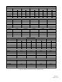
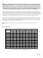
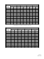
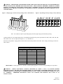
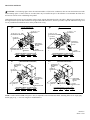
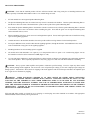
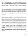
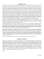
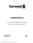
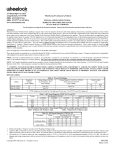
273 Branchport Avenue Long Branch, NJ 07740 (800) 631-2148 www.wheelockinc.com Thank you for using our products. INSTALLATION INSTRUCTIONS SERIES ET70/90 LOW PROFILE SPEAKERS AND SPEAKER STROBES Use this product according to this instruction manual. Please keep this instruction manual for future reference. GENERAL: Wheelock’s Series ET70/90 Low Profile Speakers and Speaker Strobes are UL Listed under Standard 1971 for Signaling Devices for the Hearing Impaired and UL Standard 1480 for Speaker Appliances. They are designed for multiple power requirements with high dBA output at each power tap. All models offer a choice of field selectable taps, 1/8W to 8W for either 25.0VRMS or 70.0VRMS audio systems. The Low Profile design incorporates a high efficiency speaker for maximum output at minimum power across a frequency range of 400Hz to 4000Hz, and features a sealed back construction for extra protection and improved audibility. The Series ET appliances also incorporate a Speaker Mounting Plate attached to the speaker for ease of installation. The Low Profile Speaker Strobes can provide a non-synchronized strobe appliance when connected directly to a Fire Alarm Control Panel (FACP), or provide a synchronized strobe appliance when used in conjunction with a Sync Module (SM), Dual Sync Module (DSM), or Power Booster (PS-12/24-8). The Strobes use a Xenon flashtube with solid state circuitry enclosed in a rugged Lexan lens to provide maximum visibility and reliability for effective visible signaling. The 241575W candela wall mounted strobes are listed at 15 candela under UL Standard 1971 and meet 75 candela intensity on axis with low current draw. The ET70 Speaker Strobes for wall mounting only are available with a choice of five UL Listed strobe options: 2415W, 241575W, 2430W, 2475W and 24110W. The ET90 Speaker Strobes for ceiling mounting only are available with a choice of four UL Listed strobe options: 2415C, 2430C, 2475C, and 24100C. All models are Listed for indoor use only with the backboxes specified in these instructions (see Mounting Options). NOTE: All CAUTIONS and WARNINGS are identified by the symbol . All warnings are printed in bold capital letters. WARNING: READ THESE INSTRUCTIONS CAREFULLY. FAILURE TO COMPLY WITH ANY OF THE FOLLOWING INSTRUCTIONS, CAUTIONS AND WARNINGS COULD RESULT IN IMPROPER APPLICATION, INSTALLATION AND/OR OPERATION OF THESE PRODUCTS IN AN EMERGENCY SITUATION, WHICH COULD RESULT IN PROPERTY DAMAGE AND SERIOUS INJURY OR DEATH TO YOU AND/OR OTHERS. SPECIFICATIONS: Table 1: UL Listed Models and Ratings Speaker Strobe dBA at 10 Feet Voltage Mounting Models Voltage (Rated Watts) (VDC/VRMS) Candela Options (VRMS) 1/8 1/4 1/2 1 2 4 8 Min Nom Max ET70 25/70 75 78 81 84 87 90 93 ------------A,C ET70-2415W 25/70 75 78 81 84 87 90 93 16 24 33 15 B,D ET70-241575W 25/70 75 78 81 84 87 90 93 16 24 33 15* B,D ET70-2430W 25/70 75 78 81 84 87 90 93 16 24 33 30 B,D ET70-2475W 25/70 75 78 81 84 87 90 93 16 24 33 75 B,D ET70-24110W 25/70 75 78 81 84 87 90 93 16 24 33 110 B,D ET90 25/70 75 78 81 84 87 90 93 ------------A ET90-2415C 25/70 75 78 81 84 87 90 93 16 24 33 15 B ET90-2430C 25/70 75 78 81 84 87 90 93 16 24 33 30 B ET90-2475C 25/70 75 78 81 84 87 90 93 16 24 33 75 B ET90-24100C 25/70 75 78 81 84 87 90 93 16 24 33 100 B *241575W models are UL Listed at 15cd and meet 75cd on axis. NOTES: 1. Strobes will produce 1 flash per second over the “regulated voltage” range. 2. All models are UL Listed for indoor use with a temperature range of +32oF to +120oF (0oC to +49oC) and maximum humidity of 85% RH. 3. dBA is rated per UL Standard 1480 for Speaker Appliances. WARNING: THESE APPLIANCES WERE TESTED TO THE OPERATING VOLTAGE LIMITS OF 16-33 VOLTS USING FILTERED (DC) OR UNFILTERED FULL-WAVE RECTIFIED (FWR). DO NOT APPLY 80% AND 110% OF THESE VOLTAGE VALUES FOR SYSTEM OPERATION. WARNING: CHECK THE MINIMUM AND MAXIMUM OUTPUT OF THE POWER SUPPLY AND STANDBY BATTERY AND SUBTRACT THE VOLTAGE DROP FROM THE CIRCUIT WIRING RESISTANCE TO DETERMINE THE APPLIED VOLTAGE TO THE STROBES. NOTE: THE MAXIMUM WIRE IMPEDENCE BETWEEN STROBES SHALL NOT EXCEED 35 OHMS. THE MAXIMUM NUMBER OF STROBES ON A SINGLE NOTIFICATION APPLIANCE CIRCUIT SHALL NOT EXCEED 47. Copyright 2000 Wheelock, Inc. All rights reserved. P83567 C Sheet 1 of 10 Table 2: Wall Mount Strobe Current Ratings (AMPS) for 24VDC Models Rated Average Current Voltage 2415W 241575W 2430W 2475W MEAN RMS MEAN RMS MEAN RMS MEAN RMS 16.0VDC 0.072 0.072 0.099 0.099 0.125 0.125 0.215 0.220 24.0VDC 0.053 0.053 0.068 0.076 0.085 0.089 0.140 0.176 33.0VDC 0.045 0.045 0.055 0.066 0.069 0.081 0.114 0.172 16.0VRMS ----0.105 ----0.125 ----0.131 ----0.217 24.0VRMS ----0.076 ----0.097 ----0.121 ----0.200 33.0VRMS ----0.069 ----0.084 ----0.105 ----0.176 Rated Peak Current * Voltage 2415W 241575W 2430W 2475W 16.0VDC 0.155 0.205 0.240 0.440 24.0VDC 0.160 0.210 0.250 0.450 33.0VDC 0.165 0.215 0.255 0.460 16.0VRMS 0.160 0.210 0.250 0.450 24.0VRMS 0.165 0.215 0.255 0.460 33.0VRMS 0.170 0.220 0.265 0.470 Rated Inrush Current ** Voltage 2415W 241575W 2430W 2475W 16.0VDC 0.110 0.110 0.110 0.110 24.0VDC 0.165 0.165 0.165 0.165 33.0VDC 0.230 0.230 0.230 0.230 16.0VRMS 0.155 0.155 0.155 0.155 24.0VRMS 0.235 0.235 0.235 0.235 33.0VRMS 0.325 0.325 0.325 0.325 Table 2A: Ceiling Mount Strobe Current Ratings (AMPS) Rated Average Current Voltage 2415C 2430C 2475C MEAN RMS MEAN RMS MEAN RMS 16.0VDC 0.105 0.105 0.158 0.161 0.330 0.385 24.0VDC 0.075 0.081 0.107 0.132 0.215 0.310 33.0VDC 0.058 0.080 0.090 0.129 0.165 0.273 16.0VRMS ----0.085 ----0.165 ----0.338 24.0VRMS ----0.085 ----0.153 ----0.314 33.0VRMS ----0.085 ----0.139 ----0.289 Rated Peak Current * Voltage 2415C 2430C 2475C 16.0VDC 0.215 0.335 0.755 24.0VDC 0.220 0.340 0.760 33.0VDC 0.225 0.345 0.765 16.0VRMS 0.220 0.340 0.760 24.0VRMS 0.225 0.345 0.765 33.0VRMS 0.230 0.350 0.770 Rated Inrush Current ** Voltage 2415C 2430C 2475C 16.0VDC 0.110 0.110 0.110 24.0VDC 0.165 0.165 0.165 33.0VDC 0.230 0.230 0.230 16.0VRMS 0.155 0.155 0.155 24.0VRMS 0.235 0.235 0.235 33.0VRMS 0.325 0.325 0.325 24110W MEAN RMS 0.276 0.296 0.169 0.232 0.138 0.203 ----0.274 ----0.241 ----0.217 24110W 0.584 0.586 0.590 0.586 0.590 0.595 24110W 0.110 0.165 0.230 0.155 0.235 0.325 24100C MEAN RMS 0.375 0.432 0.250 0.364 0.200 0.358 ----0.480 ----0.380 ----0.340 24100C 0.855 0.860 0.865 0.860 0.865 0.870 24100C 0.110 0.165 0.230 0.155 0.235 0.325 * The time duration for the peak current is 100 microseconds. ** The time duration for the inrush current is 4 milliseconds. P83567 C Sheet 2 of 10 WARNING: MAKE SURE THAT THE TOTAL AVERAGE CURRENT, TOTAL PEAK CURRENT AND TOTAL INRUSH CURRENT REQUIRED BY ALL APPLIANCES THAT ARE CONNECTED TO THE SYSTEM’S PRIMARY AND SECONDARY POWER SOURCES, NAC CIRCUITS, SM AND DSM SYNC MODULES DO NOT EXCEED THE POWER SOURCES’ RATED CAPACITY OR THE CURRENT RATINGS OF ANY FUSES ON THE CIRCUITS TO WHICH THESE APPLIANCES ARE WIRED. OVERLOADING POWER SOURCES OR EXCEEDING FUSE RATINGS COULD RESULT IN LOSS OF POWER AND FAILURE TO ALERT OCCUPANTS DURING AN EMERGENCY, WHICH COULD RESULT IN PROPERTY DAMAGE AND SERIOUS INJURY OR DEATH TO YOU AND/OR OTHERS. When calculating the total average, peak and inrush currents: Use Table 2 (for wall mount) and 2A (for ceiling mount) to determine the highest value of “Rated Average Current” for an individual strobe (across the expected operating voltage range of the strobe), and the highest value of “Rated Inrush Current” or “Rated Peak Current” (whichever is higher) of an individual strobe (across the expected voltage range of the strobe), then multiply these values by the total number of strobes; be sure to add the currents for any other appliances, including audible signaling appliances, powered by the same source and include any required safety factors. If the inrush current or peak current exceeds the power supplies’ inrush capacity, the output voltage provided by the power supplies may drop below the listed voltage range of the appliances connected to the supply and the voltage may not recover in some types of power supplies. For example, an auxiliary power supply that lacks filtering at its output stage (either via lack of capacitance and/or lack of battery backup across the output) may exhibit this characteristic. CAUTION: Strobes are not designed to be used on coded systems in which the applied voltage is cycled on and off. LIGHT DISTRIBUTION: Horizontal Angle (in deg.) 0 5 10 15 20 25 30 35 40 45 50 55 60 65 70 75 80 85 90 15W UL Min. 15.0 13.5 13.5 13.5 13.5 13.5 11.3 11.3 11.3 11.3 8.3 6.8 6.0 5.3 5.3 4.5 4.5 3.8 3.8 Typ. 15W 24 24 24 24 23 23 21 20 19 18 18 12 11 13 17 13 8 7 6 Table 3: Horizontal Plane (Wall Mount) 1575W* 30W 75W Typ. UL Typ. UL Typ. 1575W Min. 30W Min. 75W 94 30.0 46 75.0 103 93 27.0 46 67.5 103 88 27.0 45 67.5 104 87 27.0 46 67.5 100 85 27.0 43 67.5 101 80 27.0 43 67.5 98 75 22.5 41 56.3 94 71 22.5 40 56.3 89 62 22.5 39 56.3 83 52 22.5 41 56.3 81 35 16.5 36 41.3 77 32 13.5 27 33.8 60 34 12.0 30 30.0 59 27 10.5 35 26.3 71 19 10.5 29 26.3 73 11 9.0 22 22.5 53 9 9.0 17 22.5 35 10 7.5 15 18.8 30 10 7.5 15 18.8 30 110W UL Min. 110.0 99.0 99.0 99.0 99.0 99.0 82.5 82.5 82.5 82.5 60.5 49.5 44.0 38.5 38.5 33.0 33.0 27.5 27.5 Typ. 110W 149 152 151 151 148 140 135 129 124 133 121 85 95 113 81 72 50 38 43 * 1575W models are UL Listed for 15cd and meet 75cd on axis. P83567 C Sheet 3 of 10 Vertical Angle (in deg.) 0 5 10 15 20 25 30 35 40 45 50 55 60 65 70 75 80 85 90 15W UL Min. 15.0 13.5 13.5 13.5 13.5 13.5 13.5 9.8 6.9 5.1 4.0 3.3 2.7 2.4 2.3 2.0 1.8 1.8 1.8 Typ. 15W 24 24 24 24 24 21 23 22 13 9 9 8 8 8 8 8 8 7 3 Table 3A: Vertical Plane (Wall Mount) 1575W* 30W 75W Typ. UL Typ. UL Typ. 1575W Min. 30W Min. 75W 94 30.0 46 75.0 103 83 27.0 46 67.5 103 30 27.0 46 67.5 103 19 27.0 45 67.5 102 17 27.0 41 67.5 104 16 27.0 48 67.5 89 15 27.0 40 67.5 96 12 19.5 45 48.8 91 11 13.8 39 34.3 57 10 10.2 24 25.5 36 9 8.1 16 20.0 33 9 6.6 15 16.3 31 9 5.4 15 13.5 31 9 4.8 14 12.0 31 10 4.5 15 11.3 31 10 4.0 14 10.0 31 9 3.6 13 9.0 27 9 3.6 13 9.0 27 9 3.6 9 9.0 12 110W UL Typ. Min. 110W 110.0 149 99.0 149 99.0 137 99.0 120 99.0 110 99.0 129 99.0 114 71.5 119 50.6 109 37.4 66 29.7 45 24.2 43 19.8 40 17.6 40 16.5 39 14.3 39 13.2 36 13.2 37 13.2 16 * 1575W models are UL Listed for 15cd and meet 75cd on axis. Horizontal Angle (in deg.) 0 5 10 15 20 25 30 35 40 45 50 55 60 65 70 75 80 85 90 15C UL Min. 15.0 13.5 13.5 13.5 13.5 13.5 11.3 11.3 11.3 11.3 8.3 6.8 6.0 5.3 5.3 4.5 4.5 3.8 3.8 Table 3B: Horizontal Plane (Ceiling Mount) 30C 75C Typ. UL Typ. UL Typ. 15C Min. 30C Min. 75C 21 30.0 42 75.0 90 21 27.0 42 67.5 88 21 27.0 42 67.5 87 20 27.0 40 67.5 83 19 27.0 38 67.5 79 19 27.0 38 67.5 74 18 22.5 36 56.3 70 18 22.5 36 56.3 68 16 22.5 32 56.3 66 14 22.5 28 56.3 63 12 16.5 24 41.3 59 12 13.5 24 33.8 54 9 12.0 18 30.0 52 8 10.5 16 26.3 40 8 10.5 16 26.3 31 8 9.0 16 22.5 29 8 9.0 16 22.5 29 8 7.5 16 18.8 28 8 7.5 16 18.8 24 100C UL Min. 100 90 90 90 90 90 75 75 75 75 55 45 40 35 35 30 30 25 25 Typ. 100C 132 129 127 121 116 109 113 100 96 92 86 79 76 59 45 43 42 41 36 P83567 C Sheet 4 of 10 Vertical Angle (in deg.) 0 5 10 15 20 25 30 35 40 45 50 55 60 65 70 75 80 85 90 15C UL Min. 15.0 13.5 13.5 13.5 13.5 13.5 11.3 11.3 11.3 11.3 18.3 6.8 6.0 5.3 5.3 4.5 4.5 3.8 3.8 Table 3C: Vertical Plane (Ceiling Mount) 30C 75C Typ. UL Typ. UL Typ. 15C Min. 30C Min. 75C 21 30.0 42 75.0 90 20 27.0 40 67.5 92 20 27.0 40 67.5 89 20 27.0 40 67.5 86 20 27.0 40 67.5 86 20 27.0 40 67.5 83 19 27.0 38 67.5 77 17 19.5 34 48.8 70 17 13.8 34 34.3 65 15 10.2 30 25.5 62 10 8.1 20 20.0 42 8 6.6 16 16.3 35 8 5.4 16 13.5 33 8 4.8 16 12.0 31 8 4.5 16 11.3 31 8 4.0 16 10.0 31 7 3.6 14 9.0 30 7 3.6 14 9.0 27 6 3.6 13 9.0 26 100C UL Min. 100 90 90 90 90 90 75 75 75 75 55 45 40 35 35 30 30 25 25 Typ. 100C 132 129 127 121 116 109 113 100 96 92 86 79 76 59 45 43 42 41 36 WIRING INFORMATION: 1. Each doubling of rated Watts increases sound output by 3 dBA. Field selectable input terminals are provided on each unit. The following wattage selections are available: 1/8W, 1/4W, 1/2W, 1W, 2W, 4W, and 8W. Frequency range of speakers is 4004000Hz. 2. A 10µF blocking capacitor for DC supervision of audio lines by the FACP is factory wired in series with the speaker input. Figure 1. FROM PRECEDING SPEAKER OR FIRE ALARM CONTROL PANEL (FACP) Figure 2. TO NEXT SPEAKER OR END-OR-LINE RESISTOR (EOLR) FROM PRECEDING STROBE APPLIANCE OR SYBC MODULE TO NEXT APPLIANCE OR EOLR + STROBE - COM+ (OPTIONAL) 1. Low Profile Series E Speaker and Series E Speaker Strobe models have in-out wiring terminals that accept two #12 to #18 American Wire Gauge (AWG) wires at each screw terminal. Strip leads 3/8 inches and connect to screw terminals. 2. Break all in-out wire runs on supervised circuits to assure integrity of circuit supervision as shown in Figure 2. The polarity shown in the wiring diagrams is for operation of the appliances. * Refer to Sync Module instruction sheets SM (P83123) and DSM (P83177) for additional information. P83567 C Sheet 5 of 10 WARNING: THE SPEAKER AND SPEAKER STROBE APPLIANCES MUST BE FIELD SET TO THE DESIRED dBA SOUND OUTPUT LEVEL BEFORE THEY ARE INSTALLED. THIS IS DONE BY PROPERLY INSERTING JUMPER PLUGS IN ACCORDANCE WITH THESE INSTRUCTIONS. INCORRECT SETTINGS WILL RESULT IN IMPROPER PERFORMANCE, WHICH COULD RESULT IN PROPERTY DAMAGE AND SERIOUS INJURY OR DEATH TO YOU AND/OR OTHERS. Figure 3: Jumper plug is used to select tap settings which = dBA loudness. Figure 4: Tap Settings (Factory setting is 70V @ 1/2W (F)) AB C DE F GH AB C D EFGH Note: Use needle nose pliers to pull and properly insert the jumper plug to the desired tap setting. Connect speaker wires to common and positive of terminal block and select the power tap terminal for 1/8W, 1/4W, 1/2W, 1W, 2W, 4W or 8W; 25V or 70V as required (see Figures 1, 2, 3, 4 and Table 4). Each letter corresponds to a plug position of the header located on the printed circuit board. Select voltage and wattage as shown in Table 4 below. Table 4: Speaker Voltage and Wattage Connection Chart Position 25V 70V A 8 -----B 4 -----C 2 -----D 1 8 E 1/2 4 F 1/4 2 G 1/8 1 H -----1/2 I -----1/4 J -----1/8 GROUNDING: Connect ground wire to backbox. Install signaling appliance to backbox using mounting screws provided. WARNING: CHECK ELECTRICAL RATINGS SPECIFIED IN TABLE 1 AND 2 TO ENSURE PROPER ELECTRICAL INPUT. BE SURE THAT SPEAKER WIRING IS CONNECTED TO SPEAKER TERMINALS ONLY AND STROBE WIRING IS CONNECTED TO STROBE TERMINALS ONLY. CHECK TO INSURE THAT WIRING AT FACP IS CORRECT. IMPROPER ELECTRICAL INPUT CAN DAMAGE THE PRODUCT OR CAUSE IT TO MALFUNCTION. P83567 C Sheet 6 of 10 MOUNTING OPTIONS: CAUTION: The following figures show the maximum number of field wires (conductors) that can enter the backbox used with each mounting option. If these limits are exceeded, there may be insufficient space in the backbox to accommodate the field wires and stresses from the wires could damage the product. Although the limits shown for each mounting option comply with the National Electrical Code (NEC), Wheelock recommends use of the largest backbox option shown and the use of approved stranded field wires, whenever possible, to provide additional wiring room for easy installation and minimum stress on the product from wiring. A FLUSH MOUNTING B FLUSH MOUNTING (STROBE SPEAKER) (NON-STROBE) 4" SQ. X 2-1/8" EXTENSION RING * 4" SQ. X 1-1/2" BACKBOX 4" SQ. X 1-1/2" BACKBOX 4" SQ. X 2-1/8" EXTENSION RING * (2) #8-32 SCREWS (2) #8-32 SCREWS SPEAKER MOUNTING PLATE SPEAKER MOUNTING PLATE SQUARE OR ROUND GRILLE (2) #6-19 SCREWS CONE PROTECTOR SQUARE OR ROUND GRILLE MAXIMUM NUMBER OF CONDUCTORS AWG #18 AWG #16 AWG #14 AWG#12 4 4 4 4 SURFACE MOUNTING (NON-STROBE SPEAKER) C (2) #6-19 SCREWS MAXIMUM NUMBER OF CONDUCTORS AWG #18 AWG #16 AWG #14 AWG#12 8 8 8 8 SURFACE MOUNTING (STROBE SPEAKER) D SURFACE BACKBOX (SBB) SURFACE BACKBOX (SBB) (2) #8-32 SCREWS (2) #8-32 SCREWS SPEAKER MOUNTING PLATE SQUARE GRILLE CONE PROTECTOR (2) #6-19 SCREWS CONE PROTECTOR MAXIMUM NUMBER OF CONDUCTORS AWG #18 AWG #16 AWG #14 AWG#12 4 4 4 4 SPEAKER MOUNTING PLATE SQUARE GRILLE (2) #6-19 SCREWS CONE PROTECTOR MAXIMUM NUMBER OF CONDUCTORS AWG #18 AWG #16 AWG #14 AWG#12 8 8 8 8 NOTE: Surface backbox (SBB) in Figures C & D, is compatible with wiremold and conduit, mounting holes are for single-gang, double-gang, 4"sq., 3-1/2" & 4" octagon or round backboxes. P83567 C Sheet 7 of 10 MOUNTING PROCEDURES: CAUTION: Check that the installed product will have sufficient clearance and wiring room prior to installing backboxes and conduit, especially if sheathed multiconductor cable or 3/4" conduit fittings are used. 1. ET70/90 models have an integrated Speaker Mounting Plate. 2. The Speaker Mounting Plate must be oriented correctly when it is mounted to the backbox. Turn the Speaker Mounting Plate so that the arrow above the words “Horizontal Strobe” points to the top side of the Speaker Mounting Plate. 3. First mount the Speaker Mounting Plate to the backbox with the Cone Protector on; after the Speaker Mounting Plate is attached to the backbox, remove the Cone Protector before installing the grille. Next slide the grille over the Speaker Mounting Plate strobe and attach with (2) screws. 4. When terminating field wires, do not use more lead length than required. Excess lead length could result in insufficient wiring space for the signaling appliance. 5. Conduit entrances to the backbox should be selected to provide sufficient wiring clearance for the installed product. 6. Do not pass additional wires (used for other than the signaling appliance) through the backbox. Such additional wires could result in insufficient wiring space for the signaling appliance. 7. Mounting hardware for each mounting option is supplied. 8. All models can be flush mounted to a 4” square by 1-1/2” deep backbox with a 4” square 1-1/2” extension ring (Figure A or B). ET70 models can also be surface mounted to a SBB (Figure C or D). 9. Use care and proper techniques to position the field wires in the backbox so that they use minimum space and produce minimum stress on the product. This is especially important for stiff, heavy gauge wires and wires with thick insulation or sheathing. CAUTION: Always operate audio amplifiers and speakers within their specified ratings. Excessive input may distort sound quality and may damage audio equipment. Do not exceed +130% of speaker input voltage per UL 1480. Improper input voltage can damage speaker. If distortion is heard, check for clipping of the audio appliance with an oscilloscope and reduce the amplifier input level or gain level to eliminate any clipping. WARNING: WHEN INSTALLING STROBES IN AN OPEN OFFICE OR OTHER AREAS CONTAINING PARTITIONS OR OTHER VIEWING OBSTRUCTIONS, SPECIAL ATTENTION SHOULD BE GIVEN TO THE LOCATION OF THE STROBES SO THAT THEIR OPERATING EFFECT CAN BE SEEN BY ALL INTENDED VIEWERS, WITH THE INTENSITY, NUMBER, AND TYPE OF STROBES BEING SUFFICIENT TO MAKE SURE THAT THE INTENDED VIEWER IS ALERTED BY PROPER ILLUMINATION, REGARDLESS OF THE VIEWER'S ORIENTATION. FAILURE TO DO SO COULD RESULT IN PROPERTY DAMAGE AND SERIOUS INJURY OR DEATH TO YOU AND/OR OTHERS. ET70-24110W strobe models are Listed for use in sleeping or non-sleeping areas when installed in accordance with appropriate NFPA Standards and the Authority Having Jurisdiction. P83567 C Sheet 8 of 10 WARNING: INSTALLATION OF WHEELOCK 110 CANDELA STROBE PRODUCTS IN SLEEPING AREAS SHOULD BE WALL MOUNTED AT LEAST 24" BELOW THE CEILING AS FOLLOWS: (1) THE ON-AXIS (DIRECTLY IN FRONT OF LENS) LIGHT OUTPUT SHOULD BE DIRECTED AT THE EYE-LIDS OF THE SLEEPING PERSON, E.G. PILLOW END OF BED, BED HEAD; (2) NO PART OF THE BED SHALL BE MORE THAN SIXTEEN (16) FEET FROM THE STROBE NOTIFICATION APPLIANCE. INSTALLERS MUST ADVISE OWNERS AND OPERATORS OF BUILDINGS WITH SLEEPING OCCUPANTS, E.G. HOTELS AND MOTELS, TO WARN GUESTS, RESIDENTS AND EMPLOYEES TO NOT MOVE THE BED LOCATION TO A POSITION VIOLATING POINTS (1) AND (2) ABOVE OR SERIOUS INJURY AND/OR LOSS OF LIFE MAY OCCUR DURING A FIRE EMERGENCY. WARNING: A SMALL POSSIBILITY EXISTS THAT THE USE OF MULTIPLE STROBES WITHIN A PERSON'S FIELD OF VIEW, UNDER CERTAIN CIRCUMSTANCES, MIGHT INDUCE A PHOTO-SENSITIVE RESPONSE IN PERSONS WITH EPILEPSY. STROBE REFLECTIONS IN A GLASS OR MIRRORED SURFACE MIGHT ALSO INDUCE SUCH A RESPONSE. TO MINIMIZE THIS POSSIBLE HAZARD, WHEELOCK STRONGLY RECOMMENDS THAT THE STROBES INSTALLED SHOULD NOT PRESENT A COMPOSITE FLASH RATE IN THE FIELD OF VIEW WHICH EXCEEDS FIVE (5) Hz AT THE OPERATING VOLTAGE OF THE STROBES. WHEELOCK ALSO STRONGLY RECOMMENDS THAT THE INTENSITY AND COMPOSITE FLASH RATE OF INSTALLED STROBES COMPLY WITH LEVELS ESTABLISHED BY APPLICABLE LAWS, STANDARDS, REGULATIONS, CODES AND GUIDELINES. NOTE: NFPA 72/ANSI 117.1 conform to ADAAG Equivalent Facilitation Guidelines in using fewer, higher intensity strobes within the same protected area. CAUTION: Check the installation instructions of the manufacturers of other equipment used in the system for any guidelines or restrictions on wiring and/or locating Notification Appliance Circuits (NAC) and notification appliances. Some system communication circuits and/or audio circuits, for example, may require special precautions to assure electrical noise immunity (e.g. audio crosstalk). NOTE: This equipment has been tested and found to comply with the limits for a Class B digital device, pursuant to Part 15 of the FCC Rules. These limits are designed to provide reasonable protection against harmful interference in residential installation. This equipment generates, uses and can radiate radio frequency energy and, if not installed and used in accordance with the instructions, may cause harmful interference to radio communications. However, there is no guarantee that interference will not occur in a particular installation. If this equipment does cause harmful interference to radio or television reception, which can be determined by turning the equipment off and on, the user is encouraged to try to correct the interference by one or more of the following measures: 1) Reorient or relocate the receiving antenna, 2) Increase the separation between the equipment and receiver, 3) Connect the equipment into an outlet on a circuit different from that to which the receiver is connected, and 4) Consult the dealer or an experienced radio/TV technician for help. ANY MATERIAL EXTRAPOLATED FROM THIS DOCUMENT OR FROM WHEELOCK MANUALS OR OTHER DOCUMENTS DESCRIBING THE PRODUCT FOR USE IN PROMOTIONAL OR ADVERTISING CLAIMS, OR FOR ANY OTHER USE, INCLUDING DESCRIPTION OF THE PRODUCT'S APPLICATION, OPERATION, INSTALLATION AND TESTING IS USED AT THE SOLE RISK OF THE USER AND WHEELOCK WILL NOT HAVE ANY LIABILITY FOR SUCH USE. IMPORTANT: READ SEPARATE "GENERAL INFORMATION" SHEET FOR INFORMATION ON THE PLACEMENT, LIMITATIONS, INSTALLATION, FINAL CHECKOUT, AND PERIODIC TESTING OF NOTIFICATION APPLIANCES. P83567 C Sheet 9 of 10 Limited Warranty Wheelock products must be used within their published specifications and must be PROPERLY specified, applied, installed, operated, maintained and operationally tested in accordance with these instructions at the time of installation and at least twice a year or more often and in accordance with local, state and federal codes, regulations and laws. Specification, application, installation, operation, maintenance and testing must be performed by qualified personnel for proper operation in accordance with all of the latest National Fire Protection Association (NFPA), Underwriters' Laboratories (UL), Underwriters’ Laboratories of Canada (ULC), National Electrical Code (NEC), Occupational Safety and Health Administration (OSHA), local, state, county, province, district, federal and other applicable building and fire standards, guidelines, regulations, laws and codes including, but not limited to, all appendices and amendments and the requirements of the local authority having jurisdiction (AHJ). Wheelock products when properly specified, applied, installed, operated, maintained and operationally tested as provided above are warranted against mechanical and electrical defects for a period of three years from date of manufacture (as determined by date code). Correction of defects by repair or replacement shall be at Wheelock's sole discretion and shall constitute fulfillment of all obligations under this warranty. THE FOREGOING LIMITED WARRANTY SHALL IMMEDIATELY TERMINATE IN THE EVENT ANY PART NOT FURNISHED BY WHEELOCK IS INSTALLED IN THE PRODUCT. THE FOREGOING LIMITED WARRANTY SPECIFICALLY EXCLUDES ANY SOFTWARE REQUIRED FOR THE OPERATION OF OR INCLUDED IN A PRODUCT. WHEELOCK MAKES NO REPRESENTATION OR WARRANTY OF ANY OTHER KIND, EXPRESS, IMPLIED OR STATUTORY WHETHER AS TO MERCHANTABILITY, FITNESS FOR A PARTICULAR PURPOSE OR ANY OTHER MATTER. USERS ARE SOLELY RESPONSIBLE FOR DETERMINING WHETHER A PRODUCT IS SUITABLE FOR THE USER'S PURPOSES, OR WHETHER IT WILL ACHIEVE THE USER'S INTENDED RESULTS. THERE IS NO WARRANTY AGAINST DAMAGE RESULTING FROM MISAPPLICATION, IMPROPER SPECIFICATION, ABUSE, ACCIDENT OR OTHER OPERATING CONDITIONS BEYOND WHEELOCK'S CONTROL. SOME WHEELOCK PRODUCTS CONTAIN SOFTWARE. WITH RESPECT TO THOSE PRODUCTS, WHEELOCK DOES NOT WARRANTY THAT THE OPERATION OF THE SOFTWARE WILL BE UNINTERRUPTED OR ERROR-FREE OR THAT THE SOFTWARE WILL MEET ANY OTHER STANDARD OF PERFORMANCE, OR THAT THE FUNCTIONS OR PERFORMANCE OF THE SOFTWARE WILL MEET THE USER'S REQUIREMENTS. WHEELOCK SHALL NOT BE LIABLE FOR ANY DELAYS, BREAKDOWNS, INTERRUPTIONS, LOSS, DESTRUCTION, ALTERATION, OR OTHER PROBLEMS IN THE USE OF A PRODUCT ARISING OUT OF OR CAUSED BY THE SOFTWARE. THE LIABILITY OF WHEELOCK ARISING OUT OF THE SUPPLYING OF A PRODUCT, OR ITS USE, WHETHER ON WARRANTIES, NEGLIGENCE, OR OTHERWISE, SHALL NOT IN ANY CASE EXCEED THE COST OF CORRECTING DEFECTS AS STATED IN THE LIMITED WARRANTY AND UPON EXPIRATION OF THE WARRANTY PERIOD ALL SUCH LIABILITY SHALL TERMINATE. WHEELOCK IS NOT LIABLE FOR LABOR COSTS INCURRED IN REMOVAL, REINSTALLATION OR REPAIR OF THE PRODUCT BY ANYONE OTHER THAN WHEELOCK OR FOR DAMAGE OF ANY TYPE WHATSOEVER, INCLUDING BUT NOT LIMITED TO, LOSS OF PROFIT OR INCIDENTAL OR CONSEQUENTIAL DAMAGES. THE FOREGOING SHALL CONSTITUTE THE SOLE REMEDY OF THE PURCHASER AND THE EXCLUSIVE LIABILITY OF WHEELOCK. IN NO CASE WILL WHEELOCK'S LIABILITY EXCEED THE PURCHASE PRICE PAID FOR A PRODUCT. Limitation of Liability WHEELOCK'S LIABILITY ON ANY CLAIM OF ANY KIND, INCLUDING NEGLIGENCE AND BREACH OF WARRANTY, FOR ANY LOSS OR DAMAGE RESULTING FROM, ARISING OUT OF, OR CONNECTED WITH THIS CONTRACT, OR FROM THE MANUFACTURE, SALE, DELIVERY, RESALE, REPAIR OR USE OF ANY PRODUCT COVERED BY THIS ORDER SHALL BE LIMITED TO THE PRICE APPLICABLE TO THE PRODUCT OR PART THEREOF WHICH GIVES RISE TO THE CLAIM. WHEELOCK'S LIABILITY ON ANY CLAIM OF ANY KIND SHALL CEASE IMMEDIATELY UPON THE INSTALLATION IN THE PRODUCT OF ANY PART NOT FURNISHED BY WHEELOCK. IN NO EVENT SHALL WHEELOCK BE LIABLE FOR ANY CLAIM OF ANY KIND UNLESS IT IS PROVEN THAT OUR PRODUCT WAS A DIRECT CAUSE OF SUCH CLAIM. FURTHER, IN NO EVENT, INCLUDING IN THE CASE OF A CLAIM OF NEGLIGENCE, SHALL WHEELOCK BE LIABLE FOR INCIDENTAL OR CONSEQUENTIAL DAMAGES. SOME STATES DO NOT ALLOW THE EXCLUSION OR LIMITATION OF INCIDENTAL OR CONSEQUENTIAL DAMAGES, SO THE PRECEDING LIMITATION MAY NOT APPLY TO ALL PURCHASERS. 11/00 P83567 C Sheet 10 of 10