1
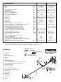
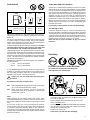
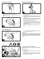
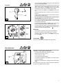
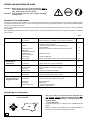
Instruction Manual
Original Instruction Manual
BCM2600
BCM3300
BCM4300
BCM2310
BCM2610
BCM3310
Important:
Read this instruction manual carefully before putting the brushcutter into operation and strictly observe the
safety regulations!
Keep this Instruction Manual!
Thank you for choosing a MAKITA product!
Table of contents
We trust that you will be a satisfied customer. By choosing a MAKITA you have chosen one of the most advanced
brushcutters.
EC declaration of conformity ............................................ 2
Packing ................................................................................ 2
Delivery inventory .............................................................. 3
Explanation of symbols ..................................................... 3
With their two-stroke gasoline engines the brushcutters can
be used anywhere, and with their fuel pump (primer) they are
unusually easy to start. They’re ideal for yardwork and greens
keeping and especially suitable for occasional use. They offer
the latest technology, ergonomic design and high ease of use
at a reasonable price.
To ensure your own safety and to get the maximum performance
out of your MAKITA brushcutter, we urge you to
read this instruction manual carefully before putting the
brushcutter into operation and to strictly observe all of the
safety regulations! Failure to observe these precautions
can lead to severe injury or death!
Page
SAFETY PRECAUTIONS
General precautions ....................................................... 4
Personal protective equipment ....................................... 4
Handling fuels / Refuelling ...........................................4-5
Putting into operation ...................................................... 5
Kickback ......................................................................... 6
Working behavior / Method of working ............................ 6
Applications for cutting tools ............................................ 6
Transport and Storage .................................................6-7
Maintenance ................................................................... 7
First Aid ........................................................................... 7
Technical data ..................................................................... 8
Components ........................................................................ 8
PUTTING INTO OPERATION
EU Conformity Declaration
The undersigned, Tamiro Kishima and Rainer Bergfeld, as
authorized by DOLMAR GmbH, declare that the MAKITA
machines,
Type: BCM2310 (351), 2610 (352), 3310 (353)
BCM2600 (352), 3300 (353), 4300 (354)
manufactured by DOLMAR GmbH, Jenfelder Str. 38, 22045
Hamburg, Germany, conforms to the basic safety and health
requirements of the applicable EU Directives:
EU Machinery Directive 98/37/EG.
EU EMC Directive 2004/108/EG.
Outdoor Noise Directive 2000/14/EG.
Starting on 29 Dec. 2009, Directive 2006/42/EG will come into
force, replacing Directive 98/37/EG. This product meets the
requirements of the new Directive.
The most important standards applied to properly meet the
requirements of the above EU Directive were:
EN 11806, EN 14982, EN 61000-4-2, EN 61000-4-3.
The conformity assessment procedure 2000/14/EG was performed per Annex V.
BCM2310: The measured sound power level is 110 db(A), the
guaranteed sound power level is 112 db(A).
BCM2610: The measured sound power level is 110.7 db(A),
the guaranteed sound power level is 112 db(A).
BCM2600: The measured sound power level is 102.8 db(A),
the guaranteed sound power level is 105 db(A).
BCM3310: The measured sound power level is 112.3 db(A),
the guaranteed sound power level is 115 db(A).
BCM3300: The measured sound power level is 103.6 db(A),
the guaranteed sound power level is 105 db(A).
Handle installation, BCM2600/3300/4300 ...................... 9
Handle installation, BCM2310/2610/3310 ...................... 9
Mounting the cutter guard ............................................. 10
Mounting the 4-tooth star blade .................................... 11
Installing the trimmer head ........................................... 11
Adjusting the line ........................................................... 12
Replacing the line .......................................................... 12
Replacing the line knife ................................................. 12
Fuel mixture / Refuelling ................................................ 13
Putting on the harness ................................................... 14
Balancing the brushcutter ............................................. 14
Quick-release buckle .................................................... 14
Start engine .............................................................14-15
Idle adjustment ............................................................. 15
REPAIR AND MAINTENANCE WORK
Instructions for maintenance ......................................... 16
Sharpening of cutting tools ........................................... 16
Cleaning the air filter ..................................................... 17
Replacing and Inspecting the spark plug ...................... 17
Lubricating the gear box ............................................... 18
Suction head in the fuel tank ........................................ 18
Cleaning the muffler opening ........................................ 18
Service and maintenance ............................................. 18
Trouble shooting .............................................................. 18
Extract from the spare part list ....................................... 19
Service, spare parts and guarantee ...........................19-20
Notes .................................................................................. 21
BCM4300: The measured sound power level is 104.7 db(A),
the guaranteed sound power level is 107 db(A).
The technical documentation is on file at DOLMAR GmbH, Abteilung FZ, Jenfelder Strasse 38, 22045 Hamburg, Germany.
Packing
Your MAKITA brushcutter comes in a cardboard box to protect
it from shipping damage.
Hamburg, 11.4. 2008
For DOLMAR GmbH
Cardboard is a raw material. We encourage you to re-use the
box or recycle it (waste paper).
Tamiro Kishima
Managing Director
2
Rainer Bergfeld
Managing Director
Delivery inventory
1.
2.
3.
4.
5.
6.
7.
8.
9.
10.
Brushcutter
Handle (version depends on model)
Harness
Cable ties (only with the BCM2600/3300/4300)
Combination tool, AF 17/19
Allen key, 4 mm
Allen key, 5 mm
Wrench, 8/10
Guard (cutting attachment guard)
Cutting tool
Shown: BCM2600
(BCM2600/3300/4300 = 4-tooth star blade, BCM2310/2610/331 = 2-line trimmer head)
11. Tool protection (BCM2600/3300/4300 only)
12. Guard extension
Instruction Manual (not shown)
If one of these parts is missing when you unpack the brushcutter,
contact your dealer!
12
Explanation of symbols
You will notice the following symbols on the brushcutter and in the instruction manual.
Read the instruction manual and follow
all warnings and safety instructions!
Maximum tool rpm
Particular care and caution!
Choke
Forbidden!
Start engine
Wear protective gloves!
STOP
Stop engine!
Wear safety shoes!
Wear head, eye, face and hearing protection!
No smoking!
No open flame!
The distance between the machine and
bystanders shall be at least 50 feet!
DANGER:
Beware of thrown objects!
Fuel and oil mixture
First aid
Do not use metal blades!
Recycling
Do not use saw blades!
CAUTION: Kickback!
(blade thrust)
CE-Marking
3
SAFETY PRECAUTIONS
General precautions
Proper use: These power brushcutters are intended for cutting
grass or heavy weeds, with the appropriate and permissible cutting tools. A brushcutter may be operated only by one person, and
only out of doors!
Improper use:
The cutting tools permissible for this brushcutter must not be used
to cut heavier material such as shrubs, bushes, heavy growth, or
thickets.
Impermissible users:
Persons who are unfamiliar with this Instruction Manual, minors,
and persons under the influence of alcohol, drugs or medication
must not operate this tool.
To ensure correct operation, the user has to read this instruction
manual to make himself familiar with the handling of the brushcutter. Insufficiently informed users will risk danger to themselves as
well as others due to improper handling (1).
- It is recommended only to lend the brushcutter to people who
have experience with brushcutters. When lending the brushcutter
to someone else, give him this Instruction Manual as well.
- First-time users should ask their dealer for basic instructions so that they can familiarize themselves with the basic
handling of gasoline-powered brushcutting.
- Children and persons under the age of 18 must not be allowed
to operate the brushcutter. Exceptions may be made for persons over 16 for training purposes under the supervision of a
qualified trainer.
- Always use brushcutters with the utmost care and attention.
- Operate the brushcutter only if you are in good physical condition. Perform all work calmly and carefully. The user must
accept liability for others.
- Never use the brushcutter after consumption of alcohol, drugs
or medication (2).
should not come in contact with mineral oil products. Always
wear protective gloves when refuelling. Frequently clean and
change protective clothes. Do not breathe in fuel vapors.
Inhalation of fuel vapours can be hazardous to your health.
Before refuelling the brushcutter make sure it is on its side
in a stabile position.
Do not spill fuel or oil. When you have spilt fuel or oil immediately clean the brushcutter. Fuel should not come in
contact with clothes. If your clothes come in contact with
fuel, change them at once.
-
1
2
Personal protective equipment
-
-
-
-
-
The clothing worn should be functional and appropriate, i.e.
it should be tight-fitting but not cause hindrance. Do not wear
either jewellery or clothing which could become entangled with
bushes or shrubs. Secure hair so it is above shoulder level. If
you have long hair, always wear a hair net!
In order to avoid head-, eye-, hand- or foot injuries as
well as to protect your hearing, the following protective
equipment and protective clothing must be used during
operation of the brushcutter:
It is recommended to wear a protective helmet; it is imperative
when working in forests. The protective helmet (1) should be
checked at regular intervals for damage and must be replaced after
5 years at the latest. Use only approved protective helmets.
The helmet face shield (2) protects your face from flying
particles from the cut and other objects. To prevent eye injury,
wear protective goggles in addition to the face shield.
Wear adequate noise protection equipment to avoid hearing impairment (ear muffs (3), ear plugs etc.). Octave brand
analysis upon request.
The forestry safety jacket (4) is equipped with special red
coloured shoulder parts. The arms and neck should always be
protected by clothing.
The protective trousers (5) are made from a nylon fabric
with 22 layers and protects against cuts. We strongly recommend its use. In any case, it is essential that a long pair of
trousers made of tough material be worn during operation of
the brushcutter.
Protective gloves (6) made of thick leather are part of the
prescribed equipment and must always be worn during operation of the brushcutter.
Safety shoes or boots (7) fitted with anti-skid sole, steel toe
caps and leg protection must always be used. Safety shoes
equipped with a protective layer give protection against cuts
and ensure a secure footing.
3
4
Handling fuels / Refuelling
4
Stop the engine before refuelling.
Keep away from open flame or sparks and do not smoke while
refuelling or mixing fuel.
Let the engine cool down before refuelling.
Fuel may contain substances similar to solvents. Eyes and skin
5
-
Ensure that no fuel or chain oil oozes into the soil (environmental
protection). Use an appropriate base.
Refuelling is not allowed in closed rooms. Fuel vapors will
accumulate near the floor (explosion hazard).
Carefully tighten the locking screw of the fuel tank and inspect
the fuel cap at regular intervals.
Change the place before starting the engine (at least 3 meters
from the place of refuelling) (6).
Fuel cannot be stored for an unlimited period of time. Buy
only as much as will be consumed in the near future.
Use only approved and marked containers for the transport
and storage of fuel. Ensure children have no access to fuel.
3 meters
(10 feet)
6
Putting into operation
-
-
-
-
-
-
-
-
Do not work alone. Another person must be nearby in case
of emergencies (within shouting distance).
Children and other persons must remain more than 15 meters
(50 feet) from the working area. Keep an eye out for animals
as well (7).
Before use always check that the brushcutter is safe for
operation:
Make sure the cutting tool is securely installed. The throttle
must automatically return to the off position when released,
and the throttle lever lock must work properly. The cutting tool
must not turn during idling. The handles should be clean and
dry. The on/off switch must function properly. The guard must
be undamaged and securely installed in the correct position.
Otherwise you are in danger of injury!
Start the brushcutter only in accordance with the instructions. Do
not use any other methods for starting the engine (8)!
Use this brushcutter and its cutting tools only for the uses they
are intended for as specified in the documentation.
Start the brushcutter only after complete assembly and
inspection. Operation of the device is only permitted after
all the appropriate accessories are attached!
The cutting tool must be equipped with its appropriate
guard. Never run the cutter without this guard!
The cutting tool must not turn during idling. If necessary adjust
the idling speed.
Before starting, make sure that the cutting tool has no contact
with hard objects such as branches, stones etc.
The engine must be switched off immediately if there are any
noticeable changes in the behavior of the equipment.
Should the cutting tool hit stones or other hard objects, immediately switch off the engine and inspect the cutting tool.
Inspect the cutting tool at frequent intervals for damage (detect hairline cracks by means of tapping - noise test). Hairline
cracks can occur in the region of the base of the
teeth after long use. Damaged cutting tools and
cutting tools with hairline cracks must not be
used any longer under any circumstances.
Operate the brushcutter only with the shoulder strap
attached, which is to be suitably adjusted before putting the
brushcutter into operation. It is essential to adjust the shoulder
strap according to the user’s size to prevent fatigue during use.
Never hold the cutter with one hand during use.
When working with the brushcutter always hold it with both
hands (9). Keep proper footing and balance at all times.
Operate the brushcutter in such a manner as to avoid inhalation
of the exhaust gases. Do not start or operate the brushcutter
in closed rooms (risk of gas poisoning). Carbon monoxide is
an odorless gas. Work only in well-ventilated places.
When taking a break or leaving the brushcutter unattended,
turn off the engine (10) and set the brushcutter down in such
a way that there is no risk of injury to yourself or others.
Never put the hot brushcutter onto dry grass or onto any combustible materials.
Shut off the engine during transport or when moving on to a
new location (10).
Never operate the engine with a faulty exhaust muffler.
Schematic
drawing
15 meters
(50 feet)
7
8
BCM2310
BCM2610
BCM3310
BCM2600
BCM3300
BCM4300
9
10
● Breaks
● Transport
● Refuelling
● Maintenance
● Tool Replacement
5
Kickback
During operation the brushcutter can kickback in an uncontrolled manner. This can happen when the cutting blade (4tooth star blade) comes into contact with hard objects such
as stumps, fenceposts, tree trunks, woody brush or large
rocks.
This can fling the brushcutter to one side with great force and
speed (injury hazard).
To avoid kickback, observe the following:
- Remove foreign objects from the cutting area and be aware of
plants and objects in the area.
11 Caution: Kickback!
- The cutting tool must be turning at full speed before starting
cuts.
- The danger of kickback is heightened in the darkened area
(illustration), especially if using a metal cutting tool!
Working behavior / Method of working
-
-
-
Use the brushcutter only in good light and visibility. During the
winter season beware of slippery or wet areas, ice and snow
(risk of slipping). Always ensure a safe footing.
Never cut above your shoulder height.
Never stand on a ladder and run the brushcutter.
Never climb up into trees to perform cutting operations with
the brushcutter.
Never work on unstable surfaces.
Make sure the cutting area is free of foreign objects such as
stones and metal items. Foreign particles can rebound (danger
of injury, 12), damage the cutting tool and cause dangerous
kickbacks.
Before commencing cutting, the cutting tool must have reached
full working speed.
12
Applications for cutting tools
Employ only the correct cutting tool for the job in hand! Do not use
tools for jobs they are not designed for.
13
2-line trimmer head (13)
Only for cutting up against walls, fences, trees, posts etc. and at
lawn edges (as an adjunct to a lawnmower).
4-tooth star blade (14)
For cutting grass or heavy weeds. Perform this cutting work by
swinging the brush cutter evenly in half-circles from left to right
(15, similar to a scythe).
Transport
-
-
-
When transporting the equipment or moving to another
working location, the brushcutter must be switched off in
order to avoid unintentionally starting the cutting tool.
Never transport the brushcutter when the cutting tool is
in operation!
The tool protection included with the equipment must always be
used if the brushcutter is transported over longer distances.
Ensure that the brushcutter is safely secured so that no fuel
can run out before transporting it in a vehicle. Empty the fuel
tank before transporting the brushcutter.
Before shipping the brushcutter, completely empty the fuel
tank.
14
15
6
Storage
-
The brushcutter must be safely stored in a dry room. Use the
tool protection for metal cutting tools. Keep the brushcutter out
of reach of children.
-
If the brushcutter is stored for a long period of time, it should be
given a thorough maintenance check and a complete inspection
at an authorized MAKITA service centre.
-
If the brushcutter is stored for a long period of time, the fuel
tank should be completely emptied and the carburetor run dry.
Fuels may only be stored for a limited period of time and could
cause deposits to form in the tank or in the carburetor.
-
Fuel remains in reserve canisters should be used for other
engines or disposed of.
16
Maintenance
-
Always make sure the brushcutter is in good working order
before using it. This includes in particular the cutting tool,
guard, harness and fuel system (check for leaks). Particular
attention must be paid to the cutting blades, which must be
correctly sharpened.
CAUTION: Metal cutting tools must be sharpened only at an
authorized service centre!
A tool which has been improperly sharpened can cause
unbalance and thus considerable danger of injury. Apart from
this, the equipment may be damaged due to vibrations.
-
When changing the cutting tool, cleaning the brushcutter and
the cutting tool etc., it is essential to switch off the engine
and pull the spark plug cap.
-
Replace cracked, bent, warped, damaged or dull cutting
tools immediately. Never straighten or weld damaged cutting
tools.
-
Operate the brushcutter with as little noise and pollution as possible. In particular check the correct setting of the carburetor.
-
Clean the brushcutter at regular intervals and check that all
screws and nuts are well tightened.
-
Never service or store the brushcutter near open flames (16)!
-
Always store the brushcutter in a locked storage area, with the
fuel tank completely empty and the carburetor run dry.
Observe the accident prevention instructions issued by the
relevant trade associations and insurance companies. Do not
make any modifications to the brushcutter - you will only be
putting your own safety at risk!
SERVICE
17
18
The performance of maintenance or repair work by the user is
limited to those activities described in this instruction manual. All
other work must be done by the MAKITA customer service (17).
Use only original MAKITA spares and accessories.
The use of non-MAKITA spares, accessories, or cutting tools increases the risk of accident. MAKITA will not accept any liability for
accidents or damage caused by the use of non-approved cutting
tools and fixing devices of cutting tools, or accessories.
First Aid
A first-aid kit should always be nearby as a precaution in the
event of an accident.
Immediately replace any items taken from the first aid kit.
When calling for help, give the following information:
Place of accident, what happened, number of persons injured,
nature of injuries, your name.
NOTE
Individuals with poor circulation who are exposed to excessive
vibration may experience injury to blood vessels or the nervous
system. Vibration may cause the following symptoms to occur in
the fingers, hands or wrists: ”Falling asleep” (numbness), tingling,
pain, stabbing sensation, alteration of skin colour or of the skin. If
any of these symptoms occur, see a physician!
19
7
Technical Data
2310 | 2610 | 3310
2600 | 3300 | 4300
Displacement
cm3
22.6 | 25.6 | 32.6
25.6 | 32.6 | 42.7
Bore
mm
31 | 33 | 36
33 | 36 | 40
Stroke
mm
30 | 30 | 32
30 | 32 | 34
Rated capacity per ISO 8893
kW
0.7 | 0.8 | 0.97
0.8 | 0.97 | 1.27
Operating speed
rpm
8,000 | 8,000 | 7,500
8,000 | 7,500 | 7,500
rpm
7,370 I 7,370 I 8,100
7,370 I 8,100 I 7,370
Maximum engine speed
with one-part metal cutting tool
1)
Maximum spindle speed
with one-part metal cutting tool 1)
rpm
10,000
10,000
Idling speed
rpm
3,000 I 3,000 I 2,500
3,000 I 2,500 I 2,500
Carburetor
Ignition system
Type
Type
diaphragm carburetor diaphragm carburetor
electronic
electronic
Spark plug
Type
NGK BPMR 8Y
Electrode gap
mm
0.6 - 0.7
NGK BPMR 8Y
0.6 - 0.7
Sound power level LWA, eq per ISO 10884 2) 4)
dB(A)
106.8 | 107.8 | 109
99.5 | 100.5 | 102
94.9 | 95.1 | 97.1
89.9 | 92 | 91.4
Sound pressure level LpA, eq at the workplace per ISO 7917 2) 5)
dB(A)
Vibration acceleration ahv, eq per ISO 7916 2) 6)
- Right handle (idling speed/maximum speed)
- Left handle (idling speed/maximum speed)
- Round handle (idling speed/maximum speed)
- Handle on shaft (idling speed/maximum speed)
m/s2
m/s2
m/s2
m/s2
7.5 / 6.1 | 4.6 / 9.5 | 4.7 / 6.5
4.8 / 8.1 | 4.4 / 6.0 | 6.3 / 7.8
Fuel consumption per ISO 8893 3)
kg/h
0.35 | 0.36 | 0.44
0.36 | 0.44 | 0.49
Specific consumption per ISO 8893 3)
g/kWh
500 | 450 | 454
450 | 454 | 386
Fuel tank capacity
l
0.6 | 0.6 | 0.8
0.6 | 0.8 | 0.9
50:1
50:1 (2%)
50:1
50:1
50:1 (2%)
50:1
14:19 | 14:19 | 17:21
5.1 | 5.1 | 5.9
14:19 | 14:19 | 14:19
5.9 | 6.7 | 7.9
5.1 / 5.7 | 2.1 / 6.2 | 4.8 / 5.5
4.0 / 6.2 | 5.0 / 5.3 | 5.3 / 6.5
Mixture ratio (fuel / MAKITA two-stroke oil)
- when using MAKITA oil
- when using Aspen Alkylat (two-stroke fuel)
- when using other oils (quality grade: JASO FC or ISO EGD)
Gear ratio
Weight (not including guard, cutting tool and fuel)
1)
2)
3)
kg
The maximum rated speed of the trimmer head is not exceeded when using a MAKITA trimmer head.
Figures derived in equal part from idle and top-speed operation (per EN-ISO 11806).
At max. power. 4) Uncertainty KWA = 2,5 dB(A). 5) Uncertainty KpA = 2,5 dB(A). 6) Uncertainty K = 2 m/s2.
Components
Type plate (BCM2600)
BCM2600
2008 123456
Serial number
Year of manufacture
1 Cutting tool
2 Gear box
3 Guard (Cutter guard)
22045 Hamburg
Germany
4 Shaft tube
5 Handle
6 Throttle (throttle trigger)
7 Combination “start/stop” (O/I) switch, half-throttle lock
8 Safety locking button (throttle trigger lockout)
9 Bowden cable guide
10 Tube handle holder
11 Stop knob for halfway throttle
12 Harness eyelet (suspension point)
13 Fuel tank cap
14 Spark plug cover
15 Starter grip
16 Type plate
17 Choke lever
18 Harness
8
Shown: BCM2600
000.000.000
Indicate when ordering spare parts!
PUTTING INTO OPERATION
STOP
CAUTION:
When working on the brushcutter always be absolutely certain to switch off the engine, pull the spark plug
cap and wear protective gloves!
IMPORTANT: Do not start the brushcutter until fully assembled and inspected!
Installing the handle
(BCM2600, BCM3300, BCM4300)
B
A
-
Loosen screws (A/1) and unscrew about 1-2 mm.
-
-
Push the grips (A/2) into the grip mounting, as shown in the
illustration.
Push the handle about 10 to 20° forward and tighten the
bolts (A/1).
-
-
Tighten the screws only enough to hold the grips while leaving them able to be turned for final positioning.
Attach the bowden cable to the shaft tube using the cable
ties (B/3) found in the enclosed pack.
NOTE:
The handle must be tilted to accommodate the operator, so
the exact angle will depend on the operator’s body size. For
easiest operation the elbows should be slightly bent, with the
wrists straight.
Installing the handle
(BCM2310, BCM2610, BCM3310)
C
-
Take the bolts and nuts (C/4, 5) and grip bracket (C/7) from
the enclosed pack.
-
Place grip (C/6) on shaft tube.
-
Attach the handle retainer plate (C/7) with bolts (C/4) and
nuts (C/5). Set the right distance between the throttle grip
(C/8) and hand grip, and tighten screws (C/4).
9
Installing the cutter guard
Important: Safety regulations and your own safety make
it imperative to use the right cutter guard with a given
cutting tool!
Warning: Use only the cutting tools shown here! It is not
permitted to use other cutting tools as this can increase danger of accidents and cause damage to the equipment!
Tool/guard combinations for the BCM2600 / BCM3300 / BCM4300
Cutting tool
Cutter guard
4-tooth star blade: Part no. 362 224 140
Part no. 351 504 101
Outside diameter: 230 mm (9"), arbour: 25.4 mm (1")
2-line trimmer head Part no. 351 502 030
Part no. 351 504 101
15 m Part no. 369 224 670
and
120 m Part no. 369 224 672
Part no. 351 504 102
Install the guard extension
Tool/guard combinations for the BCM2310 / BCM2610 / BCM3310
Cutting tool
Cutter guard
2-line trimmer head Part no. 351 502 030
Part no. 351 504 101
15 m Part no. 369 224 670
and
120 m Part no. 369 224 672
Part no. 351 504 102
Install the guard extension
Mounting the cutter guard
-
Hook the hood (A/5) by the cutout (A/1) on the lug (A/2).
-
Insert and tighten bolt (A/3) and nut (A/4).
A
Mounting the guard extension for use with trimmer head.
-
See above for installation of the cutter guard.
-
Attach the guard extension (B/6) supplied with the brushcutter to the upper part of the cutter guard (A/5), bending it to
fit the contour of the guard.
-
Attach the trimmer line knife (B/7) to the guard extension
(B/8) with the bolt (B/6).
Note: If the trimmer line has been extended (see “Adjusting
the line”) the trimmer line knife automatically cuts the line
ends to the same length during use.
6
7
B
10
8
Mounting the 4-tooth star blade
(BCM2600, BCM3300, BCM4300)
Always switch off the engine and disconnect the spark plug
cap before mounting metal cutter blades! Wear protective
gloves!
-
Remove floating disc (C/6) and thrust washer (C/5).
-
Insert the offset screwdriver 4 mm (C/1) through the winding guard and the locking disc into the opening (C/3) in the
angular gear (block the winding gear). If necessary turn the
mounting disc (C/3) slightly.
-
Position the blade (C/4), thrust washer (C/5) and finally the
floating disc (C/6) as shown.
-
Screw down the locknut (C/7) and tighten it by turning the
combination wrench counter-clockwise.
Caution: For safety reasons, after every 10 tool changes
the locknut (C/7) must be replaced with a new one. For the
order number, see the spare parts list at the end of this
manual.
C
-
Unscrew the locknut (C/7) from the shaft by turning it clockwise. If necessary, block the angle gear (see below).
Note: The locknut is provided with a left-hand thread!
- Remove Allen key and check for freedom of motion of the
cutting tool.
Installing the trimmer head
(BCM2310, BCM2610, BCM3310)
Always switch off the engine and
disconnect the spark plug cap
before mounting the trimmer head!
-
Place the mounting disc (D/3) on the shaft.
-
Insert the 4 mm Allen key (D/1) through the winding guard
and the mounting disc (D/3) into the opening on the angle
gear (blocks the angle gear). If necessary turn the mounting
disc (D/3) slightly.
-
Screw the trimmer head (D/2) onto the shaft by turning it
counter-clockwise.
-
Now tighten the trimmer head by hand.
-
Remove the Allen key and check for freedom of motion of
the trimmer head.
D
11
Adjusting the line
-
You can adjust the line to the right length at any time by lightly
tapping the trimmer head against the ground (direction of
arrow). The line cutter automatically cuts off excess line.
However, this only works when at least 3 cm of line are visible at each end.
E
-
If the line ends are shorter than 3 cm, it will be necessary
to adjust the trimmer line manually.
-
To do this, push the button firmly and pull out the line ends
forcefully.
CAUTION: Before cleaning the trimmer head, replacing the
trimmer line, or manually adusting it, make absolutely certain to switch off the engine and pull the spark-plug cap!
Replacing the line
-
Engage the nylon line in the cutout (F/6) so that one end of
the line is about 80 mm longer than the other. Then wind both
ends tightly about the spool in the direction of the arrow.
-
After winding the line, temporarily insert the ends in the cutouts
(F/4). Leave about 100 mm protruding on each end.
-
Place the spool (F/5) in the housing cover (F/2). Remove
the line ends from the cutouts (F/4) and pull them through
the metal eyelets (F/3) in the housing cover.
-
Line the housing tabs (F/1) up with the housing cover (F/2)
and push together firmly until both tabs click into position
audibly.
F
Always switch off the engine and disconnect the spark plug
cap before replacing the line!
-
Push the housing tabs (F/1) inward to remove the housing
cover (F/2).
-
Remove the spool (F/5) from the housing cover (F/2) remove
all line and line fragments.
-
Cut line (diam. 2.4 mm) to 7.5 m length.
Replacing the line knife
(BCM2310, BCM2610, BCM3310)
Before installing a new line knife, make absolutely certain
to switch off the engine, disconnect the spark plug cap,
and wear protective gloves!
G
12
-
Unscrew the screws (G/5) and remove the old line knife.
-
Mount the new line knife (G/4) as shown (towards the trimmer head) with screws (G/5).
NOTE: Do not overtighten the screws. The protective hood
is made of plastic, and overtightening can strip the threads. If
this has happened and it is not possible to mount the line knife
firmly, the protective hood must be replaced.
AVOID SKIN AND EYE CONTACT!
Fuel mixture
Fuel
50:1
Utmost care is required when handling fuel. Fuel may contain
substances similar to solvents. Refuel either in a well ventilated
room or outdoors. Do not inhale fuel vapours. Fuel vapours are
poisonous and can be hazardous to your health. Avoid eye and
skin contact with fuels and mineral oils. Mineral oil products
degrease your skin. If your skin comes in contact with these
substances repeatedly and for an extended period of time, it
will desiccate. Various skin deseases may result. In addition,
allergic reactions are known to occur. Eyes can be irritated by
contact with oil. If oil comes into your eyes, immediately wash
them with clear water.
50:1
+
If your eyes are still irritated, see a doctor immediately!
1000 cm3 (1 litre)
3
5000 cm
A
(5 litres)
10000 cm3 (10 litres)
20 cm3
20 cm3
3
3
100 cm
200 cm3
100 cm
200 cm3
This tool is powered by a high-performance air-cooled twostroke engine. It runs on a mixture of gasoline and two-stroke
engine oil.
The engine was designed for regular lead-free gasoline with
an octane number of at least 91 ROZ. If this is not available,
higher-octane gasoline may be used. This will not damage the
engine, but may impair engine performance.
The Storage of Fuel
Fuels have a limited storage life. Fuel and fuel mixtures age
through evaporation, especially at high temperatures. Aged fuel
and fuel mixtures can cause starting problems and damage the
engine.Purchase only that amount of fuel, which will be consumed over the next few months. At high temperatures, once fuel
has been mixed it should be used up in 6-8 weeks.
Store fuel only in proper containers, in dry, cool, secure
locations!
A similar situation will arise from the use of leaded fuel. To obtain
optimum engine operation and to protect your health and
the environment, only unleaded fuel should be used!
To lubricate the engine, use a synthetic oil for two-stroke air-cooled
engines (quality grade JASO FC or ISO EGD), which has to be added to the fuel. The engine was designed for use with a high
performance two-stroke oil sold by MAKITA, with a mixture ratio
of 50:1. This will ensure long engine life and reliable operation
with low exhaust emissions.
Refuelling
MAKITA high-performance two-stroke engine oil is available in
two different sizes:
1 liter
part no. 980 008 607
100 ml
part no. 980 008 606
In case MAKITA high-performance two-stroke engine oil is not
available, it is urgently recommended to use a mixture ratio of
50:1 with other two-stroke engine oils, as otherwise optimum
operation of the engine cannot be guaranteed.
FOLLOW THE SAFETY PRECAUTIONS!
Be careful and cautious when handling fuels.
The engine must be switched off!
Caution: Do not use ready-mixed fuel from petrol
stations.
Preparation of the correct mixture ratio:
50:1
when using MAKITA high-performance two-stroke engine
oil, i. e. mix 50 parts gasoline with 1 part oil.
50:1
when using other synthetic two-stroke engine oils
(quality grade JASO FC or ISO EGD), i. e. mix 50 parts
gasoline with 1 part oil.
Note:
When preparing the fuel mixture, always first mix the entire
oil quantity with half of the gasoline, and then add the rest of
the gasoline. Shake the mixture well before putting in the fuel
tank.
It is not wise to add more oil to the mixture than specified,
even if this may seem safer for the engine. More oil only leads
to increased combustion residues, which not only pollute the
environment, but are also bad for the cylinder exhaust channel
and the muffler. Furthermore fuel consumption will increase and
performance will fall.
B
-
Thoroughly clean around the tank cap (B/1) so that no dirt
can enter the fuel tank.
Before refuelling the brushcutter make sure it is on its
side in a stabile position.
-
-
Unscrew the tank cap (B/2) and carefully fill in the fuel mixture
up to the lower edge of the filler neck. Fill the tank carefully,
making sure not to spill any fuel.
Tightly screw on the cap.
Clean screw cap and tank after refuelling.
13
Putting on the harness
Balancing the brushcutter
A
B
-
Put on the harness as shown in figure A.
-
-
Adjust it so that the clip is about a hand-width above your
hipbone.
Correctly balancing the brushcutter reduces strain on the
arms while working.
-
When using the trimmer head on a level terrain, the trimmer
head should touch the ground lightly without the user having
to hold the unit.
-
In difficult terrain or when using the steel bush cutter the
brushcutter should balance about 20 cm above the ground
without the user having to hold the unit.
-
Fuel the brushcutter and clip it into the harness.
-
To balance the brushcutter, loosen the bolt (C/1). Push
the eyelet (C/2) forward to move the centre of gravity back
towards the engine, or back to move the centre of gravity
forward towards the tool.
-
When you are satisfied with the balance tighten the bolt
(C/1).
-
In an emergency, pulling the red tab (D/3) will instantly detach
the brushcutter from the operator.
C
Quick-release buckle
CAUTION:
When putting on the shoulder harness, make sure that
the red release tab is not on the inside towards the operator’s body, but on the outside, easily visible and easy to
reach!
D
Start engine
Observe accident-prevention regulations!
Do not start the brushcutter until fully assembled and
inspected!
Starting the engine
E
14
-
Move at least 3 meters (10 feet) away from where you filled
the fuel tank.
-
Make sure you have a good footing, and lay the brushcutter
on the ground in such a way that the cutting tool is not touching the ground or anything else.
Cold start
F
-
Prime the fuel pump (G/5) by pressing it several times until
you can see fuel in the pump.
-
Actuate the half-throttle lock by depressing the safety lock
(F/3), pressing in the throttle (F/1) and moving the combination switch (F/2) into the START position. Then release
throttle (F/1) and then the combination switch (F/2).
-
Turn the choke lever (G/4) to the CHOKE (closed) position.
-
Hold the brushcutter with one hand as shown in Fig. E on
page 14.
-
Pull the starter cable slowly until you feel resistance (piston
is just before top dead centre).
-
Now pull quickly and forcefully until you hear the first
audible ignition (the engine will start briefly).
-
Do not pull out the whole starter cable to its full extent and
do not let the starter handle jump back, but let it slowly
automatically rewind itself.
-
Turn the choke lever (G/4) to the RUN (open) position and
pull the starting handle again until the engine runs.
-
Once the engine has started, press the throttle (F/1) all the
way and release it again immediately. The half-throttle catch
will come out and the engine will idle.
Warmstart
-
If the engine is warmed up do not prime the fuel pump.
-
Move the combination switch (F/2) to the “I” position.
-
Do not turn the choke switch to the CHOKE (closed) position, but to RUN.
G
Stop engine
Move the combination switch (F/2) to the “O” position.
Idle adjustment
Important: The cutting tool must not rotate when the engine
is idling! If it does, adjust the idle speed.
H
-
The appropriate cutting tool must be mounted.
-
Make sure the air filter is clean.
-
Let the engine run warm.
-
Do not operate the throttle (F/1).
-
Unscrew the adjustment screw (H/6) no more than 1/8 turn
(counter-clockwise).
-
Repeat the procedure if the cutting tool still rotates during
idling.
If the cutting tool does not stop, do NOT work with the brushcutter. Take it to a MAKITA service centre!
15
REPAIR AND MAINTENANCE WORK
CAUTION: Before doing any work on the brushcutter, always
switch off the motor and pull the plug cap off the spark
plug . Always wear protective gloves!
CAUTION: Start the brushcutter only after complete assembly
and inspection!
Instructions for maintenance
For long life and trouble-free operation of your brushcutter the maintenance work listed below must be carried out regularly. Failure
to perform this maintenance work in a correct and timely fashion will void the guarantee. Failure to perform the prescribed maintenance work can lead to accidents!
Do not do any maintenance or servicing work not described in this Instruction Manual. All such work may be done only by a MAKITA
service station.
After refuelling the brushcutter 50 times, it should be given a thorough maintenance check and a complete inspection at a MAKITA
service centre.
Page
General
The brushcutter
as a whole
Clean exterior, check for damage. In case of damage,
have repaired by a qualified service centre immediately
Before each start
Cutting tool
Check for any signs of damage, that the tool is sharp
and that it is firmly secured.
Check for correct position, firm attachment and
good condition.
Check their condition and that they are firmly secured.
Guards
Screws and nuts
I/O-switch,
Safety locking button,
Throttle lever
Fuel tank cap and
fuel system
Idling speed
10
16
Functional check
16
Check for tightness
Check, the cutting tool must not turn when the engine is idling.
16
18
Every time after the
brushcutter is
switched off
Air filter
Clean
Cooling slit
Clean, check for any signs of damage.
Every 6 months
Spark plug
Suction head
Fuel tank
Starter cable
Check and replace if necessary
Have checked by a qualified workshop
Clean
Check for any signs of damage.
Annually
The brushcutter
as a whole
Check at an authorized service centre
lf the brushcutter is
not to be used for a
long period of time
The brushcutter
as a whole
Have a maintenance check carried out at a MAKITA
service centre. Store safely in a dry room.
Fuel tank
Carburetor
Metal cutting tools
Empty and clean
Run empty
Clean and lubricate lightly
Use the tool protection
18
18
Sharpening of cutting tools
4-tooth star blade
Note: The cutting tools below should be sharpened only
at a qualified workshop! Manual resharpening will result
in an imbalance of the cutting tool, causing vibrations and
engine damage.
• 4-tooth star blade
Expert sharpening can be obtained from a MAKITA service
station.
Note: To prolong its useful lifetime, the 4-tooth star blade can
be turned once until both cutting sides are blunt.
I
16
Cleaning the air filter
A
-
Loosen the screws (A/1) and remove the air filter cover
(A/2).
- Take the foam filter out of the cover.
Caution: To prevent eye injuries, do not blow out dirt
particles!
- Very dirty filters can be cleaned out using regular dishwashing liquid in lukewarm water.
- If it is very dirty clean it more often. Only a clean filter ensures
full engine power!
- Before reinstalling the air filter check the choke valve for dirt
particles, and if necessary clean it out with a brush.
- Carefully dry the air filter and reinstall it.
- First insert the air filter cover (A/2) in the groove (A/4) and
then affix with the screw (A/1).
Important: If the air filter is damaged replace it immediately!
Torn-off fabric pieces and large dirt particles can destroy
the engine!
Replacing the
spark plug
CAUTION!
NEVER touch the spark plug or spark plug cap while the
engine is running (high voltage)!
Never do maintenance work with the engine running!
A hot engine can cause severe burns. Wear protective
gloves!
The spark plug must be replaced if the insulator is damaged or
if the electrodes are severely eroded or dirty or oily.
-
B
Pull the spark plug cap (B/6) off the plug. Remove the spark
plug with a spark plug wrench (19 mm size).
Note:
Replace only with NGK BPMR8Y spark plugs!
Electrode gap
The electrode gap must be 0.6 - 0.7 mm.
Inspecting the
spark plug
-
Insert the wrench (C/7) between the housing and the cylinder,
only as shown in the illustration.
CAUTION!
Do not insert the wrench into the spark plug hole. Make
contact only with the cylinder (otherwise you may damage
the engine).
-
C
-
Firmly connect the spark plug cap to the spark plug (removed
from the engine) and hold it against the wrench using insulated pliers (away from the spark plug hole!).
Move the combination switch (I/O) to the “I” position.
-
Pull the starter cable hard.
A spark should be visible at the electrode gap.
17
Lubricating the gear box
Suction head in the fuel tank
E
D
After about 50 operating hours the gear box (D/8) should be
checked by a OLMAR service centre, and if necessary regrease.
The service centre will add the exact amount of grease, as
excessive grease will lead to overheating of the gearbox.
The felt filter (E/9) of the suction head is used to filter the fuel
taken in by the carburetor.
A periodical visual inspection of the felt filter should be conducted. For this purpose open the tank cap, and use a wire
hook to pull out the suction head through the tank opening. If
the filter has hardened or is dirty or clogged, replace it.
Insufficient fuel supply can result in the admissible maximum
speed being exceeded. It is therefore important to replace the
felt filter at least every three months to ensure a good fuel supply to the carburetor.
Servicing and maintenance
Service
Cleaning the muffler opening
After about 50 tankfuls, have the brushcutter thoroughly inspected
at a MAKITA service centre.
Regularly inspect the muffler opening (E/8). When it becomes
clogged with carbon residues, carefully scrape them out with
the suitable tool.
No maintenance and adjustment work not described in this
manual may be performed by the user. Al such work must
be performed only by a MAKITA service centre.
Trouble shooting
Fault
System
Observation
Cause
Engine will not start or
starts only with difficulty
Ignition system
Ignition spark OK
Fault in fuel supply or compression system,
mechanical defect
No ignition spark
STOP switch is depressed, wiring fault or short
circuit, spark plug or connector defective,
ignition module faulty
Fuel supply
Fuel tank full
Incorrect choke position, carburetor defective,
suction head dirty, fuel supply line bent or
interrupted
Compression
system
Inside of engine
Outside of engine
Cylinder bottom gasket defective, crankshaft
seals damaged, cylinder or piston rings worn
Poor sealing of spark plug
Mechanical fault
Starter not engaging
Broken starter spring, broken parts inside engine
Carburetor
Tank filled
Incorrect carburetor setting
Warm start problems
Ignition spark OK
Engine starts but
dies immediately
Fuel supply
Tank full
Incorrect idle speed, suction head or
carburetor dirty
Fuel tank vent defective, fuel supply line
interrupted, cable or STOP switch faulty
Insufficient power
18
Several systems
may be affected
simultaneously
Engine idling
Air filter dirty, carburetor adjustment
incorrect, muffler clogged, exhaust duct in
the cylinder clogged
Extract from the spare parts list
Use only original MAKITA spare parts. For repairs and replacement
of other parts see your MAKITA service station.
BCM2600/3300/4300
BCM2310/2610/3310
Pos.
MAKITA-No.
Qty
1
2
3
4
5
6
6
7
351 050 230
352 400 040
351 400 800
351 410 110
362 224 140
351 510 013
351 510 023
351 502 030
1
1
1
1
1
1
1
1
Tank cap cpl.
Suction head
Air filter
Spark plug NGK BPMR 8Y
4-tooth star blade
Locknut (for BCM2600/3300)
Locknut (for BCM4300)
2-line trimmer head, cpl.
Description
9
10
11
12
-
351 010 154
351 010 151
351 010 152
351 010 153
369 224 670
369 224 672
1
1
1
1
1
1
Open wrench 8/10
Allen key, 4 mm
Allen key, 5 mm
Combination tool, AF 17/19
Trimmer line, 2.4 mm dia. x 15 metres
Trimmer line, 2.4 mm dia. x 120 metres
Service, spare parts and guarantee
Maintenance and repair
The maintenance and repair modern brushcutters and safety-related components and assemblies requires qualified technical training
and a workshop equipped with special tools and testing devices.
Any maintenance or adjustment work not described in this Instruction Manual may be done only by an authorised MAKITA service
centre.
The MAKITA service centres have all the necessary equipment and skilled and experienced personnel, who can work out cost-effective
solutions and advise you in all matters.
Repair attempts by third parties or unauthorised persons will void the warranty.
Spare parts
Reliable long-term operation, as well as the safety of your brushcutter, depend among other things on the quality of the spare parts
used. Use only original MAKITA parts, marked
Only original spare parts and accessories guarantee the highest quality in material, dimensions, functioning and safety.
Original spare parts and accessories can be obtained from your local dealer. He will also have the spare part lists to determine the
required spare part numbers, and will be constantly informed about the latest improvements and spare part innovations. To find your
local distributor, please visit www.makita-outdoor.com
Please bear in mind that if parts other than original MAKITA spare parts are used, this will automatically invalidate the MAKITA
product guarantee.
19
Guarantee
MAKITA guarantees the highest quality and will therefore reimburse all costs for repair by replacement of damaged parts resulting
from material or production faults occurring within the guarantee period after purchase. Please note that in some countries particular
guarantee conditions may exist. If you have any questions, please contact your salesman, who is responsible for the guarantee of
the product.
Please note that we cannot accept any responsibility for damage caused by:
•
Disregard of the instruction manual.
•
Non-performance of the required maintenance and cleaning.
•
Exceeding of the maximum admissible speed due to incorrect carburetor adjustment.
•
Incorrect carburetor adjustment.
•
Normal wear and tear.
•
Obvious overloading due to permanent exceeding of the upper performance limits.
•
Use of force, improper use, misuse or accidents.
•
Overheating due to dirt in the coolant-air intake system including air filter.
•
Work on the brushcutter by unskilled persons or inappropriate repairs.
•
Use of unsuitable spare parts or parts which are not original MAKITA parts, insofar as they have caused the damage.
•
Use of unsuitable or old oil.
•
Damage related to conditions arising from lease or rent contracts.
•
Damages caused by disregarding loose outer bolted connections.
Cleaning, servicing and adjustment work is not covered by the guarantee. All repairs covered by the guarantee must be performed
by a MAKITA service centre.
20
Notes
21
Notes
22
Notes
23
To find your local distributor,
please visit www.makita-outdoor.com
MAKITA Werkzeug GmbH
Postfach 70 04 20
D-22004 Hamburg
Germany
Specifications subject to change without notice
Form: 995 707 481 (12.09 GB)