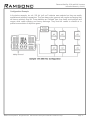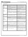
1
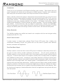
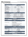
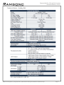
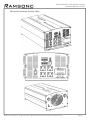
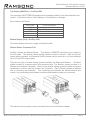
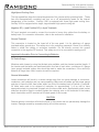
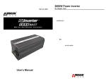
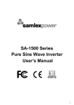
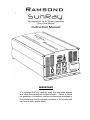
Intelligent DC to AC Power Inverters (Pure Sine Wave) Instruction Manual IMPORTANT It is important that you carefully study this instruction manual and follow the instructions contained herein. Failure to follow the guidelines, instructions, cautions and warnings contained in this manual may lead to improper operation of the inverter and may lead to injury and/or death. Ramsond SunRay 1500 and 3000 Inverters Instruction Manual (v. 34411) Introduction Thank you for your purchase of the Ramsond SunRay power inverter. With minimal care and proper treatment, this inverter will provide years of reliable service. Carefully read, understand and comply with all instructions before use. Keep this manual for future reference. Nearly a decade of advanced research, development and real-world testing in some of the most demanding conditions have yielded the world’s most sophisticated series of DC to AC pure sine wave power inverters. The Ramsond SunRay inverters are arguably the most advanced and reliable pure sine wave inverters available in the market. The design, functionality, stability, reliability and affordability of SunRay inverters are simply unrivaled. They are extremely rugged and powerful. At the same time, they are elegant in appearance, compact and lightweight. They are developed to be user-friendly and furnish real time live data and information (via LED displays and alarms) about the working conditions of the inverter, the load and battery bank. Safety Standards The SunRay inverters are certified and tested to be compliant with the most stringent safety standards (UL458, ETL, CE). About Power Inverters A power inverter, in simple terms, changes Direct Current (DC) power from a battery into conventional Alternating Current (AC) power that can use used to operate most electrical devices, instruments and appliances. Pure Sine Wave Output SunRay inverters convert the direct current (DC) power of batteries to alternating current (AC), the type of power used by modern appliances and devices. The AC power produced by SunRay inverters is pure (true) sine wave, which is the same quality of power produced by the utility grid. Pure sine wave output is a far superior (cleaner) form of output power as compared with modified sine wave power. Increasingly, most modern electrical or electronic devices such as laptop computers, stereos, laser printers, sensitive medical equipment, digital clocks, kitchen appliance with multi-stage timers, and variable speed or rechargeable tools can only function properly with pure (true) sine wave power. SunRay’s pure sine wave output provides suitable power for operation of all electronic and electrical appliances and devices, whereas the inferior modified sine wave inverters are not capable of providing suitable power to many devices. Both the function and longevity of electrical/electronic devices and appliances are improved with pure sine wave power. Pure Sine Wave Modified (Square Wave) ©Ramsond Corporation. All right reserved. Ramsond and Sunray are trademarks of Ramsond Corp. Page 1. Ramsond SunRay 1500 and 3000 Inverters Instruction Manual (v. 34411) Applications The characteristics of SunRay power inverters make them suitable for virtually all residential, commercial and industrial applications. The applications are countless, but some include the following: Off-Grid Power Source Renewable Energy (Solar, Wind, Hybrid) Emergency Backup Power RV, Mobile Homes, Trucks, Tractors, Cars Camping, Tailgating Marine Applications (Boats and Yachts) Commercial and Industrial Applications Mobile Power for Tools and Machinery Construction Sites Mobile Command Centers Mobile Medical Clinics Remote Scientific and Research Sites Mobile Laboratories Disaster Relief Modules Temporary Disaster Shelters Mobile Water Purification Systems Telecommunication, Surveillance Towers Oil Platforms, Research Sites, Defense and Military Applications Exhibition Booths, Concessions Stands ©Ramsond Corporation. All right reserved. Ramsond and Sunray are trademarks of Ramsond Corp. Page 2. Ramsond SunRay 1500 and 3000 Inverters Instruction Manual (v. 34411) General Safety Precautions Do not expose the inverter to water, mist, snow, spray, or dust. To reduce risk of hazard, do not cover or obstruct the ventilation openings. Do not install the inverter in a zero-clearance compartment. Overheating may occur. To avoid risk of fire and electronic shock, be sure all DC and AC wiring is in good condition and not undersized. Do not operate the inverter with damaged or substandard wiring. This inverter contains components that can cause arcs and spark. To prevent fire or explosion do not locate flammable materials near the inverter. Precautions When Working with Batteries If battery acid contacts skin or clothing, wash it off with soap and water immediately. If battery acid contacts your eyes, wash it out with cold running water for at least 20 minutes and get medical attention immediately. Never smoke or create sparks or flame in the vicinity of the battery or the engine. Do not drop a metal tool on the battery. The resulting spark or short circuit may cause the battery to explode. Remove jewelry and personal metal items such as rings, bracelets, necklaces, and watches when working with batteries. Jewelry may cause a short circuit creating very high temperatures which can melt metal items and cause severe burns. ©Ramsond Corporation. All right reserved. Ramsond and Sunray are trademarks of Ramsond Corp. Page 3. Ramsond SunRay 1500 and 3000 Inverters Instruction Manual (v. 34411) Technical Details – SunRay 1500 ©Ramsond Corporation. All right reserved. Ramsond and Sunray are trademarks of Ramsond Corp. Page 4. Ramsond SunRay 1500 and 3000 Inverters Instruction Manual (v. 34411) Technical Details – SunRay 3000 ©Ramsond Corporation. All right reserved. Ramsond and Sunray are trademarks of Ramsond Corp. Page 5. Ramsond SunRay 1500 and 3000 Inverters Instruction Manual (v. 34411) Mechanical Drawings (SunRay 1500) ©Ramsond Corporation. All right reserved. Ramsond and Sunray are trademarks of Ramsond Corp. Page 6. Ramsond SunRay 1500 and 3000 Inverters Instruction Manual (v. 34411) Mechanical Drawings (SunRay 3000) ©Ramsond Corporation. All right reserved. Ramsond and Sunray are trademarks of Ramsond Corp. Page 7. Ramsond SunRay 1500 and 3000 Inverters Instruction Manual (v. 34411) Front Panel – SunRay 1500 The front panel of SunRay 1500 contains the inverter’s ON/OFF Switch, LED bar displays, three (3) AC outlets, USB charging port and a Remote switch connector for connecting an optional Remote starter system. Front Panel – SunRay 3000 The front panel of SunRay 3000 contains the inverter’s ON/OFF Switch, LED displays, direct wiring High Current Terminal, four (4) AC outlets, USB charging port and a Remote switch connector for connecting an optional Remote starter system. ©Ramsond Corporation. All right reserved. Ramsond and Sunray are trademarks of Ramsond Corp. Page 8. Ramsond SunRay 1500 and 3000 Inverters Instruction Manual (v. 34411) ON / OFF (Main) Rocker Switch Before installing the inverter, be sure the main rocker switch is set to “OFF”. 115V / 60Hz AC Outlets Each outlet will supply up to 15 amps 115V / 60 Hz AC maximum, for powering appliances. Greater than 1650 watts continuous power from any outlet may cause damage to the inverter and may cause possible injury. Use the high output terminals for appliance loads greater than 15 amps (SunRay 3000 only). High Output AC Terminals (SunRay 3000 Only) There are three insulated terminals on the front panel of the inverter. These terminals are for connecting 115 volt / 60 Hz AC devices that require more than 15 amps to operate. Other uses are for connection to distributed wiring that has multiple AC outlets. Any wiring that is directly connected must be 10 gauge or larger. Facing the Front Panel, the terminals are: GND (Ground) N (Neutral) L (Live or Hot) Neutral and Ground are bonded inside the inverter to comply with the National Electric Code (NEC) requirement that any AC source must have a Neutral to Ground connection. LED Displays Bars - SunRay 1500 SunRay 1500 is equipped with two LED display bars. The display on the left shows the voltage of the battery bank. The display on the right shows the current load on the inverter LED Displays - SunRay 3000 SunRay 3000 is equipped with two LED displays. ©Ramsond Corporation. All right reserved. Ramsond and Sunray are trademarks of Ramsond Corp. Page 9. Ramsond SunRay 1500 and 3000 Inverters Instruction Manual (v. 34411) Top Display (Watt/Error) – SunRay 3000 The top display (WATT/ERROR) displays the load wattage (watt/h) of the load attached to the inverter. In the event of error, it also displays a 3 character error message. Error codes are as follows: Error Code LUP OUP OCP OLP OPP Error Description Low Voltage High Voltage Temperature Protection Overload Protection Short Circuit Protection Bottom Display (Volt) – SunRay 3000 The bottom display shows the voltage of the battery bank. Remote Starter Connection Port SunRay inverters are Remote-Ready. They feature a REMOTE connection port, located on the front panel. The optional remote starting systems connect to this port. With the optional remote starting systems, the Ramsond SunRay inverter can be turned on or off from distances up to 100 feet (30+ meters) away. There are two type of remote starting systems available; the Wired and Wireless. The Wired system consists of a remote switch and connecting wire. The Wireless system consists of a Receiver and wireless Transmitter. Both of these remote starting systems provide convenient mechanisms to start or stop the inverter from a distance. Each of these systems is supplied with a connecting wire assembly. The connecting wire (between the Receiver/Switch and inverter) can be lengthened as needed, using standard telephone cable and connectors. The optional remote systems can be purchased from your local Ramsond dealer. ©Ramsond Corporation. All right reserved. Ramsond and Sunray are trademarks of Ramsond Corp. Page 10. Ramsond SunRay 1500 and 3000 Inverters Instruction Manual (v. 34411) USB Port The front panel of the SunRay inverter is equipped with a USB port. This 5 Volt USB port can be used to charge electronic devices with USB charging capability. Rear Panel (SunRay 1500) Rear Panel (SunRay 3000) ©Ramsond Corporation. All right reserved. Ramsond and Sunray are trademarks of Ramsond Corp. Page 11. Ramsond SunRay 1500 and 3000 Inverters Instruction Manual (v. 34411) High-Speed Cooling Fans The high-speed fans keep the internal temperature of the inverter within operating limits. These fans are thermostatically controlled and turn on or off automatically based on the internal temperature of the inventor. SunRay 1500 is equipped with three high speed cooling fans. SunRay 3000 is equipped with a single, large diameter high speed cooling fan. Negative DC (−) and Positive DC (+) Input Terminals DC input terminals are used to connect the inverter to heavy duty cables from the battery or battery bank. For connection information, refer to the sections on installation. Ground Terminal This connection is located on the lower left of the rear panel. It is for attaching a 6 gauge insulated safety ground wire. This safety wire is for protecting personnel if there is an unlikely failure in either the cabling or enclosure insulation. Do not directly connect this ground connection to the negative DC terminal. This safety wire is to be connected to earth ground. Important Information Prior to Connecting to Batteries DC Cable Gauge Minimize cable losses by using the thickest wire available, and the shortest practical length. If the inverter and the battery are positioned within four feet of each other, a minimum of 0 gauge (zero gauge) insulated copper wire should be used to make the connections. If the round trip distance is longer than 4 feet, heavier wire will be required. General Information Loose connections will result in a severe voltage drop that can cause damage to connectors, conductors, and insulation and can cause sparking. Make sure all cables are the proper gauge and plan to have the ANL fuse holder within one foot of the battery bank’s Positive (+) terminal. All cable ends need to be stripped of insulation for approximately ¾ of an inch to have appropriate sized ring terminals crimped onto the bare cable ends. Appropriately sized socket wrenches should be used to carefully tighten the retaining nuts on the terminals of the battery bank, fuse holder and DC terminals on the back panel of the inverter. CAUTION Reverse polarity connection will blow the fuses in the inverter and can permanently damage the inverter. Damage caused by reversed polarity will void the warranty. ©Ramsond Corporation. All right reserved. Ramsond and Sunray are trademarks of Ramsond Corp. Page 12. Ramsond SunRay 1500 and 3000 Inverters Instruction Manual (v. 34411) CAUTION Prior to Connecting the Inverter to Batteries: Turn the rocker switch to the OFF Disconnect all load sources from inverter. Disconnect any REMOTE starting systems Disconnect any device connected to the USB port. Procedure for Connecting to Batteries Fusing Requirements NOTE: It is important that ANL 300 ampere or equivalent main battery fuses be added to the positive (+) battery cable as close as possible to the battery bank’s positive terminal. The fuse amperage rating must be sized to allow simultaneous operation of all the AC appliances to be powered, allowing for the momentary high startup current requirements of inductive loads. Use the recommended fuse block (fuse holder) and fuse, or an electrical equivalent. ANL type fuses and fuse holders are readily available from marine supply dealers. The fuses are very important to protect equipment, batteries and personnel. The fuses protect against battery explosion if the cables that connect to the inverter accidentally short. 1) Make sure the ON/OFF switch located on the front panel of the inverter is in the OFF position. 2) Make sure the inverter is not connected to any load source. 3) Make sure any option remote starting systems are disconnected. 4) Make sure any USB devices are disconnected. 5) Locate the Ground Lug Terminal at the rear of the inverter. Connect an insulated 6 gauge copper wire to the terminal. The other end of the ground wire is connected to a “proper” grounding point. Use the shortest practical length of wire. In a city, the ground wire can connect to a metal cold water pipe that goes underground. In remote locations, the ground wire can be connected to an “earth ground”. This can be an attachment to a 6 foot long copper clad metal rod driven into the ground. In the unlikely event of a short circuit, operating the inverter without proper grounding can result in electrical shock. Do not directly connect this ground wire to the Negative DC Terminal. You can connect the ground wire to the negative battery terminal. You may also connect this wire to the chassis of your vehicle or to the grounding system in your boat. NOTE: The cable ends need to be stripped of insulation for approximately ¾ of an inch at both ends. The battery ends or fuse ends need to have ring terminals crimped onto the bare cable ends. 6) Connect the Negative (−) cable ring terminal to the Negative (−) Battery Terminal. ©Ramsond Corporation. All right reserved. Ramsond and Sunray are trademarks of Ramsond Corp. Page 13. Ramsond SunRay 1500 and 3000 Inverters Instruction Manual (v. 34411) 7) Use a socket wrench to loosen and remove the Positive (+) and Negative (−) cable connector retaining nuts on the inverter. 8) Place the Negative (−) cable ring terminal onto the Negative (−) DC terminal. 9) Place the retaining nut on the terminal stud. Use the socket wrench to make a good, secure connection. 10) Recheck and make sure the DC cable fuse is installed in the fuse holder between the Positive (+) connection for the inverter. 11) Attach the Positive (+) DC cable to the Positive (+) terminal on the battery. Avoid shorting the socket wrench and carefully tighten the retaining nut. CAUTION: Making an initial connection between the positive cable and the inverter’s positive terminal may cause a spark. This is normal and is a result of capacitors in the inverter starting to charge. Because of the possibility of sparking, it is extremely important that both the inverter and the battery bank be positioned away from any source of flammable fumes or gases. Failure to heed this warning can result in fire or explosion. Do not make the positive terminal connection immediately after the batteries have been charging. Allow time for the battery gasses to vent to outside air. 12) Attach the positive cable ring terminal to the Positive (+) DC connector stud on the inverter. Replace the retaining nut and carefully tighten. Make sure the connection is tight and secure. 13) Turn on the inverter. 14) Wait 30 seconds. 15) Check to make sure that the LED light above the On/Off switch is on and not blinking. 16) Check to make sure there are not alarms sounding. 17) Check to make sure that there are no error messages on the display. 18) Prior to connecting any appliance to the inverter, make sure the appliance is turned off. 19) When you have confirmed that the appliance to be operated is turned off, plug the appliance into one of the two AC outlets on the front panel of the inverter. 20) Turn the appliance on. Reverse Polarity Reverse polarity connection will blow the fuses in the inverter and can permanently damage the inverter. Damage caused by reversed polarity will void the warranty. Connect battery positive (+) to inverter positive (red); battery negative (-) to inverter negative (black). Be aware, there will be a large spark when the last DC connection is made. Be very careful to NEVER connect DC terminals to the inverter backwards (inverter positive to battery negative). Reverse polarity connection will cause sparking and may cause fire. Reverse Polarity Protection SunRay inverters are internally equipped with replaceable spade fuse protection in case of inadvertent reverse polarity. In the event of inadvertent reverse polarity the bank/series of spade fuses will blow to prevent further damage to the inverter. This protection mechanism is not 100% fail-safe. Reverse polarity, even if inadvertent, will void the warranty of the inverter. ©Ramsond Corporation. All right reserved. Ramsond and Sunray are trademarks of Ramsond Corp. Page 14. Ramsond SunRay 1500 and 3000 Inverters Instruction Manual (v. 34411) Load Considerations When an appliance with a motor starts, it requires a momentary surge of power. This surge of power is the “starting load” or “peak load”. Once started, the appliance requires less power to continue to operate. This is known as the “continuous load”. It is important to know starting loads and continuous loads of appliances that will be powered by the inverter. Appliance power is rated in watts. This information is usually stamped or printed on most appliances and equipment. In some cases, a tool will be rated in amperes. To convert from amps to watts, multiply: AMPS × 11 5 (AC voltage) = WATTS. Then multiply this number by 90% (the efficiency of this inverter). This formula yields an approximation of the continuous wattage load of that appliance. The startup load of an appliance is a major factor of whether this inverter can power it. Startup load is momentary. With many appliances, it is approximately twice the continuous load but some appliance startup loads can be as high as eight times the continuous load. To determine if an appliance or tool will operate with this inverter, run a test. This inverter will automatically shut down in the event of an output overload, so there is no danger of damaging either the inverter or the equipment. This inverter may not properly operate some appliances with either speed control features or dimmer controls. Some appliance GFCI power cords will not operate properly while powered by this inverter. The only way to be sure of proper operation is to try it. Configuring the Battery Bank To determine the minimum battery ampere-hour rating that you will need to operate appliances from the inverter and any DC appliances powered by the battery bank, follow these steps: 1) 2) 3) 4) List the maximum continuous wattage that the inverter has to supply. Estimate the number of hours the appliances will be in use between battery recharges. This will vary depending on appliances. For example, a typical home use coffee maker draws 500 watts during its brew time of 5 minutes. It maintains the temperature of the pot, requiring 100 watts. Typical use of a microwave oven is only for a few minutes. Some longer operating time appliances are lamps, TVs, computers and refrigerator/freezers. Determine the total watt-hours of energy needed. This is done by multiplying average power consumption in watts by hours of run time. For example: 1,500 watts for 10 hours = 15,000 watt hours. To get an estimate of the maximum current (in amps) that a battery bank must be capable of delivering to the inverter, divide the load watts by ten. For example a 1,500 watt appliance load will need 150 amps at 12 volts DC. Using the 1,500 watts (or 150 Amps) for 10 hours example as above, then 150 amps is needed for 10 hours. This provides us with the basic amp hours (Ah) of battery that is required. Ten hours at 150 amps equals 1,500 Amp hours (Ah). This answer is just a beginning because there are additional factors that determine actual run time. These include: AC appliance load and time in use (basic Ah). Cable gage and length (cable losses). Charge level of the batteries (between use, chargers have to be able to fully charge the batteries). Temperature of the batteries (colder batteries provide fewer amps). ©Ramsond Corporation. All right reserved. Ramsond and Sunray are trademarks of Ramsond Corp. Page 15. Ramsond SunRay 1500 and 3000 Inverters Instruction Manual (v. 34411) Age and condition of the batteries (older batteries lose Ah capacity). Compliance with turning off unnecessary AC loads. Use of DC appliances and compliance with turning off unnecessary DC loads. Derating the Battery Bank Most lead-acid batteries have a rating expressed in amp-hours (Ah). The most common rating of Ah is “at the 20 hour rate”. NOTE: There is no relationship between Cold Cranking Amps (CCA) and Ampere Hours (Ah). For example: if a 20 Ah battery is discharged at a 1 amp rate, will take 20 hours to discharge that battery. The terms “charged” and “discharged” relate to actual battery voltage. This means that the output voltage of a nominal 12 volt battery starts at 13.2 volts (fully charged) then drops to 10.5 volts (discharged-Inverter low voltage limit). If the load on the battery causes the battery to discharge faster than the 20 hour rate, the capacity (Ah) of the battery is measurably reduced (derated). Derating is a major run time factor. Example: The user needs a one hour run time. The battery is 220Ah (20 hour rate), and the load is 220 amps; that is 100% of the Ah (20 hour rate). But in fact, a higher battery capacity is required to get the desired run time of one hour. In most cases you will need to multiply the actually battery Ah by three 3. So, if you need to run 220 amp at 1 hour, you should have at the minimum 660 Ah batteries. The installer must carefully plan the capacity of battery bank or the run time may be seriously affected. To the inexperienced installer, several trial battery capacities may be required to make sure a large enough battery capacity is available to achieve the desired run time. It is always a safe bet to oversize the battery bank as the battery capacity is likely to reduce with time. ©Ramsond Corporation. All right reserved. Ramsond and Sunray are trademarks of Ramsond Corp. Page 16. Ramsond SunRay 1500 and 3000 Inverters Instruction Manual (v. 34411) Configuration Example In the below example, six volt, 220 Ah “golf cart” batteries were selected as they are readily available and relatively inexpensive. They are deep-cycle type and with regular recharging they will have a relatively long life. These batteries are “flooded” type; they freely vent hydrogen and oxygen while under charging and heavy discharge. They must be vented to outside air to prevent accumulation of explosive gases. ©Ramsond Corporation. All right reserved. Ramsond and Sunray are trademarks of Ramsond Corp. Page 17. Ramsond SunRay 1500 and 3000 Inverters Instruction Manual (v. 34411) Troubleshooting TROUBLE Low or No Output Voltage Inverter Shutdown Reason Using incorrect type of voltmeter to test output voltage. Use true RMS reading meter. Poor contact with battery terminals. Clean terminals thoroughly. Battery Voltage Low Charge Batteries Over Load – appliances power draw exceeds the capacity of the inverter or the outlets Over Temperature – Thermal Shut Down Low Voltage Alarm Sounding Optional Remote System Not Operating Solution The battery voltage is at a critically low level causing the alarm to sound The rocker switch of the inverter is in the ON position. The connection to the REMOTE port of the inverter is not proper. Reverse Polarity In case the polarity is reversed (connecting the + and – in reverse), the internal spade fuses of the inverters will blow out as a measure of protection. This will render the inverter inoperable. Fan Turns On and Off The fan is thermostatically controller. This is a normal condition of the unit. Fan is Noisy Debris may be caught in fan Disconnect the Load – Use a bigger inverter. Try connecting to the hard-wire terminal block (if available). Allow the Inverter to Cool Down. Check the ventilation around the inverter to make sure free air flow around the inverter. Charge the batteries above the alarm protection level. Check the connections of the batteries and inverter terminals. Turn the rocker switch of inverter to the OFF position. Ensure proper connection to both the REMOTE port and the receiver (in case of wireless remote system) or switch (in case of wired remote system). Disconnect unit from batteries. Disconnect all Loads. Wait 3 minutes. Open the unit and check and replace all spade fuses. Make sure there is sufficient ventilation space behind the inverter. Disconnect unit from batteries. Disconnect all Loads. Wait 3 minutes. Check and remove any debris from the fan system. Use a vacuum cleaner to clean dust and debris from the fan inlet. ©Ramsond Corporation. All right reserved. Ramsond and Sunray are trademarks of Ramsond Corp. Page 18. Ramsond SunRay 1500 and 3000 Inverters Instruction Manual (v. 34411) LIMITED WARRANTY Applicable Products: Ramsond SunRay 1500 and 3000 Pure Sine Wave Inverters All Ramsond Corporation products are warranted to the original purchaser of the product only. Ramsond Corporation warrants the above referenced products to be free from defect or workmanship for a period of one (1) year from the original date of purchase date, subject to the limitations contained herein. In the event of product failure or malfunction, return the product or in person or by courier, shipping prepaid, to Ramsond Corporation, WPC Service Department, 4051 Haggerty Road, West Bloomfield, Michigan 48323, Tel: (248) 363-8302 Fax: (248) 363-7834. You MUST include the following to receive warranty service: 1) Proof of purchase; 2) Detailed written description of the fault or problem as well as full contact information; 3) Visible Serial Number of the unit; 4) $30 Handling fee (check, money order); 5) Return Shipping Label (prepaid) for returning to you the repaired/replaced product. The faulty/defective product will then be repaired or replaced (at our option). The repaired/replaced component/product shall then be returned to the purchaser. The purchaser shall be responsible for all shipping and handling costs of sending the defective/faulty item to us, as well as all shipping and handling costs of returning the repaired/replaced to the customer. Any import/export costs associated with shipping of repaired product outside the United States, such as brokerage fees, taxes, customs or duties are the responsibility of the customer. Certain items which are subject to normal wear and tear are specifically excluded from this Limited Warranty. Please allow up to 30 days from date that we receive the unit for repair/replacement. In the event that we are not able to repair the product, we will replace the product with same or similar unit. In the event that the model is not available, we will replace the product with an existing model with same or more superior characteristics, functionality and quality. We reserve the right to replace a defective unit with an identical refurbished unit that has been subjected to testing, which will similarly be warranted against defect or workmanship. Faulty installation, operation or maintenance of the product or attempted repair and maintenance by persons not expressly authorized by Ramsond shall render this limited warranty void. Damage resulting from failure to use the product in a manner consistent with our recommendations as contained in Instruction Manuals and other sources shall render the limited warranty void. This limited warranty specifically excludes any consequential and/or incidental damages. Additionally, this limited warranty expressly excludes labor costs provided by third parties. Although we may provide technical assistance via telephone or email to the customer, it is virtually impossible to troubleshoot all matters via telephone or remote assistance. As such, the offering by us of any technical assistance is made without any warranty or guarantee and provided on “as is” basis. It is the responsibility of each purchaser to determine whether any particular product is compliant with and permissible for use pursuant to the applicable rules, codes and/or regulations, if any, and suitable for particular use and operation. We make no representations or warranties whatsoever concerning the suitability of any merchandise for a particular use or purpose and any such warranty is expressly excluded from the terms of this limited warranty. We reserve the right to make slight modifications necessary to the merchandise for product improvement. This limited warranty shall be subject the laws of the State of Michigan and any claiming arising therefrom shall be interpreted in accordance to the laws of the State of Michigan and subject to the exclusive jurisdiction of the Courts of State of Michigan. ©Ramsond Corporation. All right reserved. Ramsond and Sunray are trademarks of Ramsond Corp. Page 19. Ramsond SunRay 1500 and 3000 Inverters Instruction Manual (v. 34411) For comments and questions, please email or write to: Ramsond Corporation Public Relations Dept 4051 Haggerty Road West Bloomfield, Michigan 48323 USA Tel: (866) 777-7071 Fax: (248) 363-7834 Email: www.ramsond.com For accessories and parts, please visit Ramsond’s store at www.Ramsond.com ©Ramsond Corporation. All right reserved. Ramsond and Sunray are trademarks of Ramsond Corp. Page 20.