1
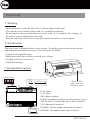
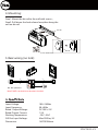
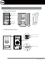
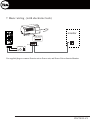
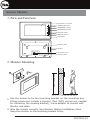
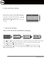
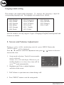
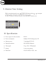
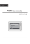
Yale 7402
2 Wire Video Intercom System
USER MANUAL
User Setup (1)
Door Station Call Tone ...
Intercom Call Tone ...
DoorBell Tone ...
Clock ...
Next Page ...
Select Item About
Exit
OK
YDV7402-V1
Power Unit
1. Warning
- Don’t dismantle or alter the unit. Fire or electric shock could result.
- The unit must be installed and wired by a qualified technician.
- Do not connect any non specified power source to the N, L terminals, Fire, damage to
the unit, or system malfunciont can result.
- Keep the unit away from water or any other liquid, risk of fire or electric shock.
2. Introduction:
The power unit is designed for two wire systems. It supplies power to the outdoor station,
indoor monitor and other accessories. The features are as follow:
• Universal AC input/full range
• Multi protection: sho rt circuit, overload, over voltage
• Cooling by free air convection
• DINrail mounting
60m m
3. Terminal Description:
90
mm
N
N
L
SW
PA P- P+
CN2
LED
BUS(IM) BUS(DS)
CN1
140mm
* Press on both
sides of the cover
and lift to remove
N: AC input.
L:AC input.
SW: Swit ch termina l.
LED: Power indicator,always on when plug in p ower.
CN2: PA and P+ terminal should be sho rt-circuited.
CN1: Buscontrol termina l.
BUS(IM): Indoor monitor conne ction termina l.
BUS(DS): Door st
ation conne ction termina l.
YDV7402-V1
4. Mounting:
Step1: Mount the din rail to the wall with screws ;
Step2: Pull down the lock release lever,then hang the
unit on din rail.
Din rail
Din rail
Lock release lever
5. Basic wiring (no lock):
2
BUS BUS
(DS) (IM)
NP
NP: Non-polarized
PA P- P+
L1
L2
N
L
2
NP
L1
L2
AC~
Note:PA&P+ terminal must be short-circuited.
Input Voltage:
Input Frequency:
Rated Output Voltage:
Rated Output Current:
Working Temperature:
SW Port Input Voltage:
Dimension:
100~240Vac
50~60Hz
DC 28V+/-2V
1.5A
-100C~500C
Max.230Vac, 2A
140*90*60mm
YDV7402-V1
Exterior Unit
1.Parts and Functions
Camera Lens
Speaker
176 mm
Night View LED
Nameplate
Call Button
Microphone
Rain Cover
90 mm
23 mm
2.Terminal Descriptions
ON
1 2
Lock Control Jumper
Doorstation Code DIP
1 2
ON
1 2 3
MIC adjustment
SPK adjustment
BUS
S2+ SPL S1+
Main Connect Port
YDV7402-V1
• Lock Control Jumper: Not to be removed
• Doorstation Code DIP: To be used when additional exterior units are used in the same system.
• Main Connect Port: To connect the interior monitor and electornic lock/s.
BUS: Connection to interior monitor, no polarity.
PL: External lock power input, connect to the power positive(power +).
S1+, S2+: Lock power(+) output. To locks can be connected through the unit.
S-: Lock power(-) output, connect to the power(-) input of locks only when using the camera to
power the locks, if using the external power supply for the locks, the S- will not be connected).
3. Specification
Lock Power supply:
12Vdc, 300mA(Internal Power)
Power Consumtion:
NO, COM dry contact:
1W in standby, 12W in working
Max. 48V dc 1.5A
Unlocking time:
Working temperature:
1 to 9 seconds, set by Monitor
-10ºC ~ 45ºC
4.Mounting
1
2
3
4
1
2
160-165cm
YDV7402-V1
5. Placing Name Label
Remove the plastic cover to open the transparent name label holder, cut a paper to size
print name. Insert paper on to name holder re insert plast cover back to the panel
ON
1 2
Backside
name label
6. Adjusting Camera Angle
Use a screwdriver to loosen the screw. Adjust the desired
anlge and then fix the screw back.
YDV7402-V1
7. Basic wiring (with electronic lock)
ON
1 2
AC~
monitor
BUS(IM) BUS(DS)
BUS(DS)
BUS PLS1+ S2+ S-
BUS(IM)
+
Use supplied plugs to connect Exterior unit to Power unit, and Power Unit ot Interior Monitor.
YDV7402-V1
Interior Monitor
1. Parts and Functions
Digital TFT LCD screen
UNLOCK(▲) button
MONITOR(▼) button
INTERCOM(●) button
TALK(◄) button
MENU(►) button
Microphone
Mounting hook
Speaker
Connection Port
BT1
BT2
EH
GND
VD
DIPS
ON
1 2 3 4 5 6
L1
L2
Mounting hook
145~160 cm
2. Monitor Mounting
1. Use the scrwes to fix the mounting bracket on the mounting box.
Fitting accesories include a bracket (Two 4X25 screws are needed
for fastening the mouting bracket), 2 wire adaptor to connect with
Monitor and cable.
2. Wire the system correctly (see Outdoor Station Installation) then
hang the monitor on the mounting bracket firmly.
YDV7402-V1
3. Basic Door Release Operation
1. Press CALL button on outdoor station, the
Monitor rings, at the same time, the screen
displays the visitor image.
DS-1
00:23
2. Press TALK ( ) button on monitor, you can
communicate hands free with the visitor for 90
seconds.After finishing communication,press
"TALK" button again to end the communication.
If nobody answers the phone, the screen will be turned off automatically after 30
seconds.
UNLOCK ( ) button to open the door for the
3. During talking state, Press
visitor. If two locks are connected to door camera,press corresponding unlock button
to open the matching door.
MONITOR ( ) , the screen
4. When the monitor is in standby mode, press
can display the view of outside. If multi door stations are installed, press
INTERCOM ( ) button to enter camera switch mode. Select Camera 1 ...
item, the screen will display the image from the first door camera.Similarly.
Select Camera 2 ... item to choose the second one. Select Camera 3 ... item
to choose the third one. Select Camera 4 ... i t e m t o c h o o s e t h e f o u r t h o n e .
(Press"MONITOR" button again to end monitoring.)
4. Intercom Function
When the monitor is in standby mode, press
INTERCOM ( ) button to enter Intercom
Function page. Use ▲ / ▼ button to move upward
/ downward to select the item you want, press
MENU (
Intercom
Intercom Call ...
Inner Call ...
Direct Call Guard Unit ...
Select Item
Exit
OK
YDV7402-V1
Intercom Call : User in one apartment can call
Intercom Call
other apartments in the system. The namelist will be
[ 00 ]
Alex
[ 01 ]
Joe
created automatically by the system. Selete a name
[ 02 ]
Ray
[ 03 ]
Alice
[ 04 ]
Mary
on the screen then press
MENU ( ) button to
[ 05 ]
Martin
dial.(Note 1. Press "MENU " button again to redial.
Last/Next
Exit
Calling
2. The DIP switches codes of each monitor must set
differently)
Inner Call : If multi Monitors are installed in the
same apartment, select Inner Call, all the other Monitors will ring at the same time.
The Monitor that answers the call will start the conversation, while the other monitors will
stop ringing (Note: DIP switches setting of all monitors must be the same).
Direct Dial Guard unit: A Monitor can be assigned as Guard Unit Monitor; when the
Guard Unit Monitor answers the call, conversation with the guard person is started.
5. Basic Setup Instructions
Ring Tone Settings
Acess Door Station Call Tone, Inercom Call Tone or DoorBell Tone item on User
Setup (1) page by pressing MENU ( ) A total of 12 pieces ring tones can be selected.
/ button to select last/next ring tone, press MENU ( ) button to save and exit.
Use
Door Station Call Tone : Sets the ring tone from outdoor station calling.
Intercom Tone : Set the ring tone from other apartments calling.
DoorBell tone : Set the ring tone calling from door bell.
User Setup (1)
Door Station Call Tone
Door Station Call Tone ...
Intercom Call Tone ...
DoorBell Tone ...
Clock ...
Next Page ...
Select Item
About
Exit
Selected:
1 Carmen
2 Ding Dong
3 Rain
4 For Alice
OK
06
5 Sonatine
9 Do Re Me
6 Edelweiss
10 Happy Birthday
7 Going Home
11 Jingle Bells
8 Congratulation 12 Telephone Ring
Last/Next
Cancel
Save&Exit
YDV7402-V1
6. Date and Time Setting
Select Clock... item on User Setup (1) page.
Input date and time by pressing ▲ / ▼ button
to increase / decrease the value; press
/
button to select last/next digit. Press
INTERCOM ( ) button to save and return
last page.
Clock
2011- 04 - 22
17:17
Inc/Dec
Last/Next
Save&Exit
7. Advanced Settings
How to enter the advanced installation setting page
step1
step2
step3
User Setup (1)
04/22/2011
03:25
Fir
PM
1. Press
2. Press
3. Press
H/W :
S/W:
Local addr:
Unlock timing:
Unlock2 select:
Video standard:
Language:
Door Station Call Tone ...
Intercom Call Tone ...
DoorBell Tone ...
Clock ...
Next Page ...
Select Item
About
Exit
step4
OK
Exit
DT14-CT a1.3
V17.11.418.00
-------
Code Number:[0000]
[0010]:Remove remote
[0011]:Add remote
[8000]:Master 0
[8001]~[8003]:Slaver 1~3
[8004]:Guard unit
[8005]:Not guard unit
[8006]:Panel on as slaver called [8007]:P
[8008]:MM/DD/YYYY
[8009]:DD/MM/YYYY
[8010]:Unlock mode 0
[8011]:Unlock mode 1
[8012]:12-Hour system
[8013]:24-Hour system
[8014]:Unlock2 on
[8015] :Unlock2 o
[8021]~[8029]:Unlock time set 1~9s
Inc/Dec
Exit
Last/Next
) button in standby mode. A calendar will appear, press MENU button again.
) button at User Setup (1) page to enter About information page.
UNLOCK ( ) button and hold for 2s.
4. Press / button to increase/decrease the value and / button to select the setting
number ,press MENU ( ) to save the settings after inputing 4 digits number,press
button to return last page.
MENU (
INTERCOM (
YDV7402-V1
How to set secundary/slave monitors to view image when call is made
In default mode and when receiveing a call, the master and slave monitors will ring at the
same time, but just the master monitor will display the image, while the slave monitors
will not. This setting can be changed to have all the monitors (master and slave), dispaly
the image at the same time while receiving a call by using the code 8006 on each slave
monitor.
How to set the unlock lock mode
Two types of unlock modes:
1. Power-on- to-unlock type: Unlock mode = 0 (default setting)
2.power-off-to-unlock: Unlock mode = 1
The code number of 8010 is used to set the unlock mode to 0
The code number of 8011 is used to set the unlock mode to 1
Unlock time:
The unlock time can also be changed. It can be set from 1 to 9 seconds.
The code number from 8021 to 8029 are used to set the unlock time, being the last digits
the number of seconds (1~ 9 seconds).
2 locks control
The monitor can be set to control 2 locks while you should set the unlock2 item to "on "
state.
The code number of 8015 is used to set the unlock2 OFF. This setting is for only one lock.
The code number of 8014 is used to set the unlock2 ON. This setting is to control two locks.
Note: - During a call or while monitoring outside, press
UNLOCK ( ) button. Two unlock icons will be
showed. Press
UNLOCK ( ) button to release
MONITOR ( ) to release
the second lock. Press INTERCOM ( ) button to
return to last page.
Restoring the monitor to default settings will not
change this parameter.
1
2
YDV7402-V1
Language mode setting
This monitor can support multi languages. T o c h a n g e t h e l a n g u a g e , input the
corresponding language code. The language code number are as follows:
8101: English
8102: French
8103: Spanish
8104: Italian
8105: German
8106: Dutch
8107: Portuguese
8108: S-Chinese
8109: T-Chinese
8110: Greek
8111: Turkish
8112: Polish
8113: Russian
8114: Slovakia
8115: Hungray
8116: Czech
Note:the monitor can only support 4 types of languages.English,French,Spanish and
German are default.
8. Screen and Volume Adjustment
During a c a l l o w h i l e monitoring o u t s i d e , press MENU Button,the
ADJUST MENU will be displayed
Press ▲ / ▼ button to select the adjustment item; press
/
button to decrease /
increase the value.
1. Scene mode selection: Total of 4 screen modes
can be selected:
Normal, User, Soft and Bright. Whenever you
modify Brightness or colour, Scene item will be
set to User mode automatically.
Scene
Bright
Color
Ratio
Talk Volume
Select Item
Brightly
6
6
16:9
2
Exit
Dec
Inc
2. Brightness and Color: to adjust brighness
and color of the screen
3. Talk Volume: to ajust intercom volume during a call.
4. Press "MENU" button to exit the setting mode.
YDV7402-V1
9. Monitor Time Setting
While in monitoring mode, press
INTERCOM button and use ▲ / ▼ to navigate
to Monitor Time Set Option. Press MENU button to enter.
Use ▲ / ▼ button to increase/decrease value and MENU button to save
Monitor Time Select
Current :
Last/Next
01min
Cancel
Save&Exit
10. Specification
● Power supply for indoor monitor:
DC24V
● Power consumption:
Standby 0.5W; Working status 5W
● Monitor screen:
7 Inch digital TFTLCD
● Display Resolutions:
800*3(RGB)*480pixels
● Video signal:
1Vp-p, 75Ω, CCIRstandard
● Wiring:
2 wires, non-polarity
● Dimension:
143(H)×242(W)×23(D) mm
YDV7402-V1