1
PCL-848A/B
MULTIFUNCTION IEEE-488
INTERFACE CARD
PCL-848A/B MULTIFUNCTION
IEEE-488 INTERFACE CARD
USER’S MANUAL
This documentation and software routines contained in the PCL848A/B software
diskette are copyrighted 1989 by Advantech Co.. Ltd. All rights are reserved.
Advantech Co., Ltd. reserves the right to make improvements of the products
described in this manual at any time without notice.
No part of this manual may be reproduced, copied, translated or transmitted, in any
form or by any means without the prior written permission of Advantech Co., Ltd.
Information provided in this manual is intended to be accurate and reliable.
However, Advantech Co., Ltd. assumes no responsibility for its use; nor for any
infringements of rights of third parties which may result from its use.
PC-LabCard is a trademark of Advantech Co., Ltd. IBM and PC are trademarks of
International Business Machines Corporation. MSDOS and QuickBASIC are trade
marks of Microsoft Corporation BASIC is a trademark of Dartmouth College. Intel is
a trademark of Intel Corporation. Nl PC-II is a trademark of National Instruments.
Part No. 2003848000
Printed in Taiwan
Rev. A1
Apr 2001
Contents
1. GENERAL INFORMATIQN .................................................................. 1
1.1. Introduction to the Product ......................................................................... 1
1.2. Description of the Documentation .............................................................. 2
2. INSTALLATION ...................................................................................... 4
2.1. Inspection .................................................................................................... 4
2.2. Switch and Jumper Setting ......................................................................... 4
2.2.1.
2.2.2.
2.2.3.
2.2.4.
2.2.5.
I/O Base Address and Wait State Setting .......................................................... 5
Firmware Address Setting ................................................................................. 6
Operating Mode Setting ..................................................................................... 7
DMA Level Setting ............................................................................................ 7
Interrupt Level (IRQ) Setting .............................................................................. 7
2.3. Installing the Card ....................................................................................... 7
2.3.1. Preparation ....................................................................................................... 7
2.3.2. Installing the Card into a PC ............................................................................. 8
2.3.3. Function Check ................................................................................................. 9
3. PROGRAMMING REFERENCE ........................................................ 10
3.1.
3.2.
3.3.
3.4.
Introduction ............................................................................................... 10
Using the BASIC CALL Statement ........................................................... 11
Using QuickBASIC and BASIC Compiler ................................................. 13
The IEEE-488 Driver Routines ................................................................. 13
3.4.1. AHORT ........................................................................................................... 14
3.4.2. DEVCLR (Device Clear) Purpose : ................................................................. 15
3.4.3. DEVICE .......................................................................................................... 16
3.4.4. ENTER Purpose : ........................................................................................... 17
3.4.5. ENTERA ......................................................................................................... 18
3.4.6. EOL ................................................................................................................ 20
3.4.7. INIT ................................................................................................................. 21
3.4.8. LLO ................................................................................................................. 23
3.4.9. LOCAL ............................................................................................................ 24
3.4.10. OUTPUT Purpose : ........................................................................................ 25
3.4.11. OUTPUTA ...................................................................................................... 26
3.4.12. PPOLL ............................................................................................................ 28
3.4.13. PPOLLC ......................................................................................................... 29
3.4.14. PPOLLU ......................................................................................................... 31
3.4.15. REHOTE ........................................................................................................ 32
3.4.16. SEND ............................................................................................................. 33
3.4.17. SPOLL ............................................................................................................ 35
3.4.18. STATUS Purpose : ......................................................................................... 36
3.4.19. TIMEOUT Purpose : ....................................................................................... 37
3.4.20. TRIGGER Purpose : ....................................................................................... 38
3.4.21. ERRPTR ........................................................................................................ 39
4. PROGRAMMING TECBNIQUES ...................................................... 41
4.1.
4.2.
4.3.
4.4.
4.5.
4.6.
Interactive Data Transfer .......................................................................... 41
Set IEEE-488 Printer ................................................................................ 43
Voltage Measurement with a DVM ........................................................... 44
AD500 PMU Programming ....................................................................... 45
Multiple Device Triggering ........................................................................ 47
Interrupt Handling ..................................................................................... 49
5. ADVANCED PROGRAMM1N~ TECBNIQUES ............................... 51
5.1.
5.2.
5.3.
5.4.
Direct Memory AcceAs (DMA) .................................................................. 51
Transfer Speed ......................................................................................... 54
Interrupt ..................................................................................................... 55
Hore about the SEND Command ............................................................. 56
6. DIGITAL OUTPUT ............................................................................... 57
7. TBEORY OP OPERATION.................................................................. 58
7.1. Introduction ............................................................................................... 58
7.2. Block Diagram Description ....................................................................... 58
8. TROUg3LB5BOOTING ........................................................................ 60
8.1.
8.2.
8.3.
8.4.
Introduction ............................................................................................... 60
Periodia Maintenance ............................................................................... 60
Troubleshooting Procedure ....................................................................... 60
Part List ..................................................................................................... 62
9. BUS TUTORIAL .................................................................................... 64
9.1. General Bus Description ........................................................................... 64
9.2. Bus Structure ............................................................................................ 66
9.2.1. IEEE-488 Connector Pin Assignment ............................................................. 66
9.2.2. IEC-625 Connector Pin Assignment ................................................................ 67
9.3. Management Lines ................................................................................... 67
9.4. Bus Commands ........................................................................................ 68
9.5. Servioe Request and Serial Polling .......................................................... 68
9.6. Parallel Polling .......................................................................................... 69
9.7. Code Summary ......................................................................................... 69
9.8. Randshake Lines ...................................................................................... 71
9.9. Other Bus Lines ........................................................................................ 73
9.10. Bus Operating Considerations .................................................................. 73
10. ASCII TABLE ...................................................................................... 74
11. NEC7210 RBAD / WRITE REGISTSR ............................................. 76
12. SUMMARY OF TBE IEEE-488 LIBRARY FUNCTIONS ............. 77
Figures
Fig. 2.2 Location of switches and jumpers ................................................... 4
Fig. 7-1 PCL-848A/B Block Diagram ................................................................ 59
1. GENERAL INFORMATIQN
1.1. Introduction to the Product
The PCL-848A/B IEEE-488 interface card is a valuable addition to your PC that
allows you to communicate with over 2000 products, made by over 200 manufacturers, in over 14 countries. The IEEE488-1978 standard that this IEEE-488 card
implements is the most widely used international standard for information transfer
between computer and electronic instruments. There are numerous publications and
articles that may be used in conjunction with this manual to assist you to understand
the interface standard. The IEEE reference document may be ordered by writing to the
IEEE Service Center, 445 Uoes Piscataway, NJ 08854, USA.
The IEEE-488 interface card provides the hardware (electrical and mechanical) and
software required for you to interface your PC to the IEEE-488 bus. The software is
packaged in read-only-memory (firmware) to provide versatile and easy-to-use IEEE488 function extensions for your current programming language or operating system.
Firmware cannot be accidentally erased or overwritten and it is always available for
use by application programs. This manual provides a programming reference (Section
3.) and programming techniques (Section 4. and 5.) to assist you in writing your own
application programs.
The key features of this interface card include:
* Operating in one of the two modes (switch selectable).
Mode A : Compatible with PCL-748 and use the on-board firmware driver.
Mode N : Software compatible with National Instrument PC-II and IBM-PC GPIB adaptor and use the driver and software developed for them.
* Implementation of the entire IEEE-488 standard.
* Powerful and easy-to-use software command set. Fewer arguments and simple
initialization.
* Software driver is in on-board firmware. Requires no additional disk operation when
using BASIC or Turbo Pascal.
* On-board RAM for working space. No system memory space is needed for the
IEEE-488 interface operation.
* Built-in 16 bit digital output port provides a convenient and economical solution for
signal switching and digital control applications. The D/O port is compatible with
the daughter boards: PCLD-785 Relay Output Eoard, PCLD-786 SSR & Relay
Driver Board and PCL-789 Amplifier Multiplexer Board.
CHAPTER 1 GENERAL INFORMATIQN
1
BASICA, BASIC compiler and Quick-BASIC are supported as standard languages. C
and Pascal language support packages can be ordered separately as PCL-748-C and
PCL-748-P.
The software can change the PC printer port to an IEEE-488 device. The PrtSc (print
screen) key, all print statements, word processing and spreadsheet programs that use
printer driver in BIOS can use IEEE-488 printers.
* High speed direct memory access (DMA) with the ability to handle 64K byte
arrays.
* Programmable system controller, active controller or device functions.
* All device functions, addresses, interrupt conditions, and parallel poll responses are
programmable.
* Automatic initialization. Interface parameters are set to default when starting using
the interface. Parameters can still be changed by calling the initialization routine.
* DIP switch selectable wait states (0/2/4/6 wait states) to ensure the compatibility to
very high speed PC’s.
* PCL-848A offers the connectors of the IEEE-488 standard while PCL-848B uses
the 25 pin D type connectors for the IEC-625 standard.
* Each device on the IEEE-488 bus can be assigned with its own terminator.
1.2. Description of the Documentation
Information in this manual is given at several levels of detail and is organized to allow
you to work through the TUTORIAL, PROGRAHMING REFERENCE and
PROGRAMMING TECHNIQUES sections.
If you have no IEEE-488 experience, go to Section 9. after this section.
The IEEE-488 TUTORIAL in Section 9. is designed to give you a thorough understanding of how the IEEE-488 General Purpose Interface Bus (GP-IB) works. Topics
in the TUTORIAL should be read in sequence if you have no IEEE-488 background
and intend to write application programs. With a solid understanding of the basic
IEEE-488 concepts, followed by returning to the PROGRAMMING REFERENCE,
and the PROGRAMMING TECHNIQUES, you should be able to program almost
any IEEE-488 bus system without interface problems.
2
PCL-848AB
User's Manual
If you are familiar with the basic concepts of the IEEE-488 bus you may want to
begin reading the Section 3. PROGRaI~MING REFERENCE. This section describes
the statement syntax and techniques to use the IEEE-488 driver in the firmware.
Section 4. PROGRAMMING TECHNIQUES will show you how the functions are
used in typical applications and also provide you with some useful program examples
for your own applications. All the examples are written in BASICA language.
If you want to know more details about this IEEE-488 interface card, please refer to
Section 5. ADVANCED PROGRAMMING TECHNIQUES. This section tells you
how to set DMA, how to modify transfer speed and how to use interrupts.
This manual is intended to be accurate and is organized to give you a quick reference
for programming ideas and the concepts of the IEEE-488 bus.
CHAPTER 1 GENERAL INFORMATIQN
3
2. INSTALLATION
2.1. Inspection
When unpacking, check the unit for signs of shipping damage (damaged box, scratches,
dents, etc). If there is any damage to the unit or it fails to meet specifications, notify
your localt sales representative immediately. .
2.2. Switch and Jumper Setting
This IEEE-488 interface card has two DIP switch (SW1 and SW2), 1 one slide switch
(SW3) and three jumpers (JP1, JP2 and JP3). The: setting must be coincident with the
application program.
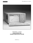
Legend:
CN1: GP-IB connector CN2: Digital output
connector
SW1: I/O port base address and wait states
SW2: Firmware base address SW3: Operation
mode (PCL-748 or NI PCÑI I )
JP1: DACK channel JP2: DRQ channel JP3:
IRQ level Fig. 2.2 . Location of switches and
jumpers
Fig. 2.2 Location of switches and jumpers
4
PCL-848AB
User's Manual
2.2.1. I/O Base Address and Wait State Setting
The I/O ports base address and the number of wait states are selectable by the 8
position DIP switch SW1. The base address can be set anywhere in the I/O address
area from hex 200 to hex 3F8 and the wait states can be set to 0, 2, 4, or 6. Refer to
3 Fig. 2.2. for the locations of the DIP switches SW1. Factory settings of these
switches are hex 2B0 and zero wait state.
This multifunction interface card takes 16 addresses of I/O port following the base
address. The digital output port takes the addresses of BASE+0 and BASE+1 and the
IEEE-488 interface takes the addresses from BASE+8 to BASE+15. When using the
IEEE-488 driver routines, the IEEE-488 interface base address must be set to BASE+8
where the BASE is the set by DIP switch SW1. The default address of the IEEE-488
interface is then hex 2B8.
The switch settings for various base addresses and wait states are illustrated as below:
Note : - 0N = 0, 0FF = 1
- 1..8 are switch positions
- W0..W1 correspond to wait state
- A4..A8 correspond to address lines of the PC bus
- * means factory setting
Switch position (SW1)
1
2
3
4
5
Occupied
A8
A7
A6
A5
A4
Addresses
-------------------------------------------------------------------0
0
0
0
0
200-20F
0
0
0
0
1
210-21F
.
.
.
*
0
1
0
1
1
2B0-2BF
.
.
1
1
1
1
0
3E0-3EF
1
1
1
1
1
3F0-3FF
-------------------------------------------------------------------Switch position (SW1)
7
8 Wait state(s)
W1
W0
-----------------------------------------------*
0
0
0
0
1
2
1
0
4
1
1
6
-----------------------------------------------CHAPTER 2 INSTALLATION
5
2.2.2. Firmware Address Setting
The IBEE-488 interface driver routine is stored in the on-board i EPROM. The
memory address of this firmware can be selected by SW2. The memory segment of
the firmware can be from hex 8000 to s hex FC00. Factory setting is hex D000.
The range of these locations is out of the 640K system memory of i the IBM PC, PC/
XT and PC/AT. However, choice of this location must be made to avoid any conflict
with other interface cards. When two or more IEEE-488 interface cards are used in one
PC, the location settings must be different in order to have different working space
although the firmware code is the same.
The SW2 positions l to 5 determine the address bits Al8 to Al4. ~ Address bit A19 is
always 1. Address bits below A13 (included) are not cared.
Memory Location Segment
(hex)
SW2-1
A18
SW2-2
Al7
SW2-3
A16
SW2-4
A15
SW 2-5
A14
----------------------------------------------------------------------------------------------------8000
0
0
0
0
0
8400
0
0
0
0
1
8800
0
0
0
1
0
.
.
Reserved
A000
0
1
0
0
.
.
CRT Display
B000
0
l
1
0
.
.
Factory Setting
D000
1
0
1
0
.
.
System ROM
F000
1
1
1
0
FC00
1
1
1
1
--------------------------------------------------------------------------------------* 0 : ON
l : OFF
0
0
0
0
1
This multifunction IEEE-488 interface card takes 10K bytes of the memory space
including 8K byte RON and 2K byte RAM. The starting . address of the working
RAM is offset 8K bytes from the ROM starting address.
6
PCL-848AB
User's Manual
2.2.3. Operating Mode Setting
SW3 is a slide switch to select the operating mode. When it is set to “A”, this card is
compatible with the easy-to-use PCL-748 IEEE-488 interface card except there is no
real time clock. When SW3 is set to “N”, this card becomes NI PC-II compatible. 3
It depends on the users which mode is selected. If the software package is already
developed for PC-II, then mode “N” can be used to eliminate the software effort.
Dowever, for new software developing, mode “A” is recommended to get all the
benefit of PCL-848A/B. PCL-848A/B does not support the software driver to use
mode “N” and this manual offers the information for mode “A” 3 operation only.
2.2.4. DMA Level Setting
The PCL-848A/B is designed to permit DMA (Direct Memory Access) = data
transfer between IEEE-488 bus and the system RAM of the PC. The DMA level is
set by JP1 and JP2. The JP1 is for DACK signal path while the JP2 is for DRQ. The
settings of JP1 and JP2 must be coincident. For example, if the JP1 is set to DACK 3,
then JP2 must be set to DRQ 3.
2.2.5. Interrupt Level (IRQ) Setting
The PCL-848A/B is designed to permit access to interrupt level 2 up to level 7 and
the interrupt is initiated by the NEC7210 GP-IB interface controller. The selection is
made by setting JP3.
Note :
Although the IRQ level can be set from IRQ 2 to IRQ 7 _ on the
board, the firmware supports IRQ 2, 3, 5, and 7 only.
2.3. Installing the Card
2.3.1. Preparation
Discharge any static electricity by touching the back of the system unit before you
handle the board. You should avoid contact with materials that create static electricity
such as plastic, vinyl, and styrofoam.
CHAPTER 2 INSTALLATION
7
The IEEE-488 interface card is setup at the factory of default setting:
Jumper/Switch
Selection
Default setting
SW1 1-5
SW1 7-8
SW2
SW3
JP1
JP2
JP3
I/O port base address
Wait states
Firmware base address
Operating mode
DACK level
DRQ level
IRQ level
Hex 2B0
0
Hex D000
A
1
1
7
Refer to Section 2.2. for other configurations.
2.3.2. Installing the Card into a PC
The procedure to install the IEEE-488 interface card is as following:
1. Turn off the computer and any peripheral devices (such as printers and monitors).
2. Disconnect the power cord and any other cables from the back of the computer.
Turn the system unit so the back of the . unit faces you.
3. Remove the system unit cover (See your computer user’s guide if necessary).
4. Locate the expansion slots at the rear of the unit and =; choose any unused slot.
5. Remove the screw that secures the expansion slot cover to the system unit. (Save
the screw to secure the IEEE-488 interface card retaining bracket).
6. Carefully grasp the upper edge of the IEEE-488 interface 3 card. Align the hole in
the retaining bracket with the hole on top of the expansion slot, and align the gold
striped edge connector with the expansion slot socket. Press the board firmly into
the socket.
7. Replace the screw in the expansion slot retaining bracket.
8. Replace the system unit cover. Connect the cables you ~emoved in step 2.
8
PCL-848AB
User's Manual
2.3.3. Function Check
Confirm proper operation by connecting an IEEE-488 instrument to i the bus and
attempting to operate it with a program written in BASIC.
Here is an example procedure using an HP3478A digital voltmeter s and a short
BASIC program.
1. Connect the HP3478A DVM to the IEEE-488 bus connector Of this card on the
back of the PC with a standard IEEE-488 s cable. On the PCL-848B, the connector
is 25 pin D type defined by IEC-625 and a PCL-15488-2 IEC-625 to IEEE-488
cable must be used.
2. Set the device address of the HP3478A DVM to 23.
3. Turn on the HP3478A DVM and the PC.
4. Get into BASICA or GWBASIC environment.
5. Key in the following BASIC statements:
10
20
30
40
50
60
70
80
90
100
110
DEF SEG=&BD000
OUTPUT%=3 : ENTER%=6
ADDR%=23 ‘GP-IB address of up3478A
TMP$=”F1" ~UP3478A DVM programming code
CALL OUTPUT%(ADDR%,TMP$)
FOR I=1 TO 10
D$=SPACE$(80)
CALL ENTER%(ADDR%,D$)
PRINT D$
NEXT I
END
6. Execute the program. It will display the 10 readings i measured by the HP3478A
DVM and thus confirm proper ~ operation.
If the system fails this test, check for these common problems:
1. The instrument requires a special terminator. Check the instruments instruction
manual and Section 3. of this manual.
2. The programming command syntax for the instrument may be incorrect. Check the
examples in the instrument manual.
3. Check all electrical connections.
If there is still any problem, contact your local sales representative for further
assistance.
CHAPTER 2 INSTALLATION
9
3. PROGRAMMING REFERENCE
3.1. Introduction
The PCL-848A/B interface card contains the resident firmware that provides IEEE488 language extensions for your PC. The firmware (software programmed into a readonly-memory) appears transparent to the users and the function inside is called by the
IEEE-488 commands.
All of the routines in the firmware are written in assembly language to insure maximum data transfer rates. Each routine combines bus error checking. The routines also
check parameter values to insure that appropriate bus protocol is followed.
The routines in the firmware transfer commands and data on the IEEE-488 BUS
through the use of statements that are given English I language names like OUTPUT,
ENTER and INIT. Statement OUTPUT sends a data string to the IEEE-488 BUS in
much the same way as <PRINT “string”> sends data to the screen. Statement ENTER
looks ] for data coming from the IEEE-488 BUS, similar to the way <INPUT X$>
waits for a keyboard entry to assign to the string variable X$. Statement INIT clears
the interface and sets up specific operating modes on the interface card as the CLS
clears the screen and establishes specific operating conditions.
The data strings that you include in a SEND statement can be as general as the strings
you would use in a <PRINT> statement. The SEND function interprets IEEE-488
commands and data in any order that you choose. It also allows you to build powerful
commands that can be assigned to a single string variable that has a name and purpose
that is meaningful to you. The IEEE-488 BUS commands are separated by one or
more spaces. There is no difficult syntax to learn and only standard IEEE-488
mnemonics are used. The function of each mnemonic is performed exactly as defined
in the IEEE-488-1978 standard.
The firmware converts your command and data strings to specific control codes for
the IEEE-488 bus controller chip. It also passes back received data and interface status
conditions to your program. Received information may be used directly by your
program and the status codes (those returned by the STATUS function) may be used
to determine various interface operating conditions or to detect syntax errors in the
statements.
The next section discusses the CALL statement of BASICA and QuickBASIC. All of
the examples are given in BASICA, the syntax and use of each function is similar to
those of QuickBASIC version 2.0, 3.0 and 4.0.
10
PCL-848AB
User's Manual
3.2. Using the BASIC CALL Statement
The firmware routines on the IEEE-488 interface card, can be thought of as BASIC
language extensions. The extensions consist i of the statements ABORT, CLEAR,
ENTER, ENTERA, EOL, INIT, LLO, LOCAL, OUTPUT, OUTPUTA, PPOLL,
PPOLLC, PPOLLU, REMOTE, SEND, SPOLL, STATUS, TIMEOUT, TRIGGER
and ERRPTR. These routines allow ~ the PC to execute much faster because they are
written in assembly language. Another advantage is that the statement names only
represent address offsets and these offsets may be given any name that you prefer.
Calling the routines in the firmware when using BASICA requires three steps.
1. The location of the firmware routines must be defined using a DEF SEG statement.
This statement defines the current is egment address of the firmware and it is
determined by the setting of SW2. Since the factory setting is hex D000, as
statement as following is required.
DEF SEG = &HD000
Note:
In most cases, the default setting of SW2 (hex D000) i is all right
for operation. Keep this setting unless another add-on card
occupies this memory space and cannot be changed.
2. The called routine must be located within the segment as defined by an offset
variables. For example, the OUTPUT routines has an offset of 3 and a statement to
define the offset variables is:
OUTPUT% = 3
Note:
The OUTPUT% variabLe can be other variable names.
3. The parameters needed by this routine must be defined ~‘ according to the requirement of the application. Then, the s routine is executed by using a CALL statement.
The state ments are such as:
ADDR% = 23
D$ = “F1RA”
CALL OUTPUT%(ADDR%,D$)
Additional information on the DEF SEG and CALL statements is available in your
BASIC manual.
CHAPTER 3 PROGRAMMING REFERENCE
11
Every called routine must define its entry address with an offset from the current
segment. For ease of reference all IEEE-488 routine offsets are at three byte increments and start at the top of the segment. For example, the INIT routine is at an
offset of 0 (zero), the OUTPUT routine is at an offset of 3, the ENTER routine is at
an offset of 6, and so on.
Please note that the program offsets must be entered exactly as shown for each
interpreter routine. The offsets determine where the program will branch and an
improper location can cause the PC to ignore all inputs except the power switch. This
is true of all BASIC CALL subroutines and is not a limitation of the interface board.
When you assign the offset, you are explicitly telling the CPU of the PC where to
look for its next instruction. Because it is running an assembly language routine, it
cannot check the validity, purpose, or use of each instruction the way it does as with
BASIC instructions. For that reason, it depends on receiving the proper offset address
and then assumes that the instructions are correct. The DEF SEG statement and all
offset address may be assigned with a single BASIC statement and never require
reassignment within your program. That means you can “set it and forget it” and get
on with the job of solving your program rather than being concerned about addressing
details.
Each routine also access the parameters those are received from or passed back to the
BASIC program. These parameters are shown in parentheses following the program
offset variable for each statement.
There are some limitations in BASICA that have, unfortunately, placed restrictions on
the called routines.
* The order, number, and type of variables passed to the routines must be exactly as
shown for each routine. This is because BASIC only passes pointers of variables
and does not provide a variable type identifier.
* The BASIC interpreter and compiler (such as Compiled BASIC and QuickBASIC)
have different string variable requirements. -t The default is for the BASIC
interpreter. For the BASIC compiler, you must call the INIT routine to set the
SETTING% bit 8 to be “1” to tell the firmware routines to handle the 3 parameters
in a different way.
* Passed parameters must be variables and cannot be constants.
* BASIC may change its source code if a statement changes the contents of the passed
string. This situation can be avoided by assigning a value to the string argument
before calling the firmware routines. The statement to define a blank string to
receive data is recommended is as:
D$ = SPACE$(255).
12
PCL-848AB
User's Manual
The programming examples and interpreter routines have been written to work around
these limitations and they should not placed any restrictions on your IEEE-488
applications.
3.3. Using QuickBASIC and BASIC Compiler
Calling the IEEE-488 routines in the firmware when using BASIC compiler or
QuickBASIC is almost the same way as using BASICA except the following two
areas.
1. When using the IEEE-488 routines in BASICA programming, the l; user does not
need to call the INIT routine (initialization) except the default setting is not used.
Uowever, the user need to call the INIT routine before calling any other IEEE488
routines when programming in BASIC compiler or QuickBASIC. When calling the
INIT routine, the bit 8 of the parameter SETTING% must be set to “1”.
2. The syntax to call the IEEE-488 firmware routines when programming in BASICA
is as:
CALL OUTPUT%(ADDR%,D$)
however, in BASIC compiler or QuickBASIC, the syntax is: lt
CALL ABSOLUTE(ADDR%, D$,0UTPUT%)
Note:
When using QuickBASIC, the user needs to enter the developing environment by the command
QB/L
to load the library USERLIB.EXE. Otherwise, the word “ABSOLUTE” cannot be
recognized.
3.4. The Driver Routines
The following twenty one routines can be called by programs written in BASICA,
BASIC Compiler or QuickBASIC to access the IEEE-488 interface. QuickBASIC has
the same syntax as BASIC Compiler.
CHAPTER 3 PROGRAMMING REFERENCE
13
3.4.1. AHORT
Purpose:
This command aborts all activities on the interface bus bys
Offset :
AHORT%=9
Syntax :
CALL AHORT%
---BASIC
CALL AHSOLUTE(AHORT%)
---BASIC Compiler
Parameter:
None.
Bus Activity :
IFC is pulsed for 100 microseconds.
REN is set true
ATN is set false.
Remark :
This command can be called only in system controller mode An error will occur if this
command is called in the nonsystem control mode.
14
PCL-848AB
User's Manual
3.4.2. DEVCLR (Device Clear) Purpose :
This command sends a Selective Device Clear (SDC) command to a specified device or
sends a Device Clear (DCL) to the interface bus.
Offset :
DEVCLR%=15
Syntax :
CALL DEVCLR%(ADDR%)
---BASIC
CALL ABSOLUTE(ADDR%,DEVCLR%)
---BASIC Compiler
Parameter :
ADDR% -
The address of the device to be cleared. If 0 <= ADDR% <= 30, it
executes a Selective Device to the i device specified, otherwise, it
executes a Device Clear to the bus.
Bus Activity :
- If 0 <= addr <= 30
ATN is set true.
UNL is sent.
LAD is sent.
MTA is sent.
SDC is sent.
- If addr < 0 or addr > 30
ATN is set true.
DCL is sent.
CHAPTER 3 PROGRAMMING REFERENCE
15
3.4.3. DEVICE
Purpose:
This command installs an IEEE-488 device driver in place of s the LPT1:, LPT2:,
LPT3:, COM1: and COM2: driver. The IEEE-488 devices then can be accessed using
the system commandst in MS-DOS.
Offset :
DEVICE%=57
Syntax:
CALL DEVCLR%(ADDR%,PORT%)—BASIC
CALL ABSOLUTE(ADDR%,PORT%,DEVCLR%)
—BASIC Compiler~
Parameter:
ADDR% -
The address of the device which is assigned to
LPTn: or COMn:. If ADDR% < 0 or ADDR% > 30, the replacement of LPTn: or COMn: is disabled.
PORT% -
The port number which is to be replaced with the
IEEE-488 device.
1 : assigned to LPT1:
2 : assigned to LPT2:
3 : assigned to LPT3:
4 : assigned to COM1:
5 : assigned to COM2:
Bus Activity:
None.
16
PCL-848AB
User's Manual
3.4.4. ENTER Purpose :
This command enters a string from a device or from the interface. Reading iB
terminated upon receiving the terminator specified by the EOL command or the
maximum length of data bytes is reached.
Offset :
ENTER%=6
Syntax :
CALL ENTER%(ADDR%,DS)
---BASIC
CALL ABSOLUTE(ADDR%,D$,ENTER%)
---BASIC Compiler
Parameter :
ADDR% - Device address. If 0 < ADDR% <= 30, then it enters the string from
the specified device, ~ otherwise, it enters the string from the interface.
D$ -
The string from the specified device or from the interface.
Bus Activity :
- If 0 <= addr <= 30
ATN is set true.
REN is set true.
UNL is sent.
TAD is sent.
MLA is set.
ATN is set false.
Data string is entered.
- If addr < 0 or addr > 30
ATN is set false.
Data string is entered.
Remark:
The entered string length can be read by STATUS.
CHAPTER 3 PROGRAMMING REFERENCE
17
3.4.5. ENTERA
Purpose :
This command enters a long string (can be up to 65535 bytes) from a specified
device or from the interface. Reading is terminated upon receiving the terminator, or
when the specified length is reached, or on timeout. The string is put into the
specified segment in the memory. The starting address of the received string has
offset 0 in that segment.
Offset :
ENTERA%=51
Syntax :
CALL ENTER%(ADDR%,DATASEG%,LENGTH%) ----BASIC
CALL ABSOLUTE(ADDR%,DATASEG%,LENGTH%,ENTERA%)
----EASIC Compiler
Parameter :
ADDR% -
The address of the device the input string comes from, If 0 <=
ADDR% <= 30, the specified device is the talker, otherwise,
the talker is the previously defined one.
DATASEG% -
The memory segment where the string is to be put. The starting
address offset is 0.
LENGTH% -
The input string length. The range is from 0 to 65535.
Bus Activity :
- If 0 <= addr <= 30
ATN is set true. UNL is sent. TAD is sent. MLA is set. ATN is set false.
Data string is entered.
- If addr < 0 or addr > 30
ATN is set false. Data string is entered.
18
PCL-848AB
User's Manual
Example:
10
DEF SEG=&HD000 ‘ Define location of firmware :
20
ENTERA%=51 : STATUS%=42 ‘ Define routine offset
.
.
40
ADDR%=8 ‘ GP-IB Device 8 as data source
50
DATASEG%=&u3000 ‘ Put data to this segment
60
LENGTH%=&RFFFF ‘ Set buffer length 65535 byte
70
CALL ENTERA%(ADDR%,DATASEG%,LENGTu%) ‘Enter data
80
CONDITION%=9 : COUNT%=0
90
CALL STATUS%(CONDITION%,COUNT%) ‘Read data length
100
DEF SEG=&u3000 ‘ Define location of data
110
IF COUNT%<0 THEN CNT=655361+COUNT% ELSE CNT=COUNT%
120
FOR I= 1 TO CNT
130
PRINT CER$(PEEK(I-1)); ‘Print the data string
140
NEXT I
150
DEF SEG=&HD000
.
.
CHAPTER 3 PROGRAMMING REFERENCE
19
3.4.6. EOL
Purpose :
This command sets the terminators of input and output strings for the specified
device. The terminators of all devices are set to default values if this command is not
called.
Offset :
EOL%=12
Syntax :
CALL EOL%(ADDR%,OUTEOL%,OUTEOL$,INEOL%,INEOLBYTE%)
----BASIC
CALL ABSOLUTE(ADDR%,OUTEOL%,OUTEOLS,INEOL%,INEOLBYTE%,EOL%)
----BASIC Compiler
Parameter :
ADDR% -
The address of device to be assigned the terminator.
The range is from 0 to 30.
OUTEOL% -
Terminator type appended to output string. The default value is 0.
0 Terminated with both OUTEOL$ and EOI.
1 Terminated with EOI only. OUTEOL$ not used. i;
2 Terminated with OUTEOL$ only. EOI is disabled.
OUTEOL$ -
End-Of-Line string which is to be sent following output strings.
The string can be 8 characters long at maximum. The default string
is 13, 10 (CARRIAGE RETURN and LINE FEED).
INEOL% -
The condition for which the input string is terminated. The default
value is 0.
0 Terminated when INEOLBYTE$ received or EOI true or input
string full.
1 Terminated when EOI true or input string full.
INEOLBYTE$ -
The ASCII code of the character upon which the input string will
be terminated when INEOL% is 0. The default is 10 (LINE
FEED).
Bus Activity :
None.
20
PCL-848AB
User's Manual
3.4.7. INIT
Purpose :
This aommand initializes the interface card and sets the relative parameters. It can be
neglected if the parameters used are all default values.
Offset :
INIT%=0
Syntax :
CALL INIT%(IOPORT%,MYADDR%,SETTING%)
----BASIC
CALL ABSOLUTE(IOPORT%,NYADDR%,SETTING%,INIT%)
----HASIC Compiler
Parameter :
IOPORT% -
I/O port of NEC7210, from hex 008 to hex 2F8 by increment of
hex 010. The value is the I/O base address plus 8. The default
value is hex 2B8 since the base address (determined by SW1) of
this card is set to hex 2B0 at factory.
MYADDR% -
IEEE-488 address of the IEEE-488 interface card. The range-is
from 0 to 30. The default value is 21.
SETTING% -
An integer (16 bit) to set the DMA LEVEL, IRQ LEVEL and
other parameters. The default value is 0, i.e., 8ASIC interpreter,
system controller, no IRQ and no DMA.
CHAPTER 3 PROGRAMMING REFERENCE
21
For more information about bit 12,14,15 of setting, please refer to Section 5. ADVANCED PROGRANMING TECUNIQUES.
Bus Activity :
This command takes following action when it is called.
1. Initialize the NEC7210 GP-IB controller.
2. Set relative parameters for the NEC7210.
3. Store the I/O base address, IRQ level and DMA level into working RAM.
Examples :
1) Set IEEE-488 interface card to mode : Non-system controller, No IRQ, No DMA.
Bus address is 21. I/O port address is hex 2B8 (SW1 is set at hex 2B0).
50 INIT% = 0
60 MYADDR% = 21
70 IOPORT% = &u2B8
80 SETTING% = &H008F
90 CALL INIT%(IOPORT%,MYADDR%,SETTING%)
.
.
2) Set IEEE-488 interface card to mode : System controller, IRQ level 7 and DMA
level 1. IEEE-488 address is 0. I/O port address is hex 3C8 (SW1 is set at hex 3C0).
.
.
50 INIT% = 0
60 MYADDR% = 0
70 IOPORT% = &H3C8
80 SETTING% = &H001D ' Bit 0, 2, 3, 4 are all 1
90 CALL INIT%(IOPORT%,MYADDR%,SETTING%)
.
.
3) Set IEEE-488 interface card to BASIC Compiler mode, System controller, No IRQ,
DMA level 2. Bus address is 21. I/O port address is hex 2B8.
.
.
50 INIT% = 0
60 MYADDR% = 21
70 IOPORT% = &H2B8
80 SETTING% = &H0102
90 CALL INIT%(IOPORT%,MYADDR%,SETTING%)
.
.
22
PCL-848AB
User's Manual
3.4.8. LLO
Purpose :
This command executes a Local Lockout (LLO) to disable a device’s front panel. It is
received by all devices on the bus, whether or not they are addressed to listen.
Offset :
LLO%=18
Syntax :
CALL LLO%
----BASIC
CALL ABSOLUTE(LLO%)
----BASIC Compiler
Parameter :
None.
Bus Activity :
ATN is set true. LLO is sent.
CHAPTER 3 PROGRAMMING REFERENCE
23
3.4.9. LOCAL
Purpose :
This command executes a Go To Local (GTL) or clears the REN line to enable a
device’s front panel controls.
Offset :
LOCAL%=21
Syntax :
CALL LOCAL%(ADDR%)
----BASIC
CALL ABSOLUTE(ADDR%,LOCAL%)
----BASIC Compiler
Parameter :
ADDR% -
The address of the device to be set local. If 0 <= addr <=30, then it
executes a Go To Local (GTL) command to the specified device.
Otherwise, it sets the REN line false (High).
Bus Activity :
- If 0 <= addr <= 30
ATN is set true.
UNL is sent.
LAD is sent.
MTA is sent.
GTL is sent.
- If addr < 0 or addr > 30
REN is set false.
ATN is set false.
24
PCL-848AB
User's Manual
3.4.10. OUTPUT Purpose :
This command outputs a string to the specified device or to the interface bus. After
the string is sent, the terminator 3 specified by the EOL command is sent.
Offset :
OUTPUT%=3
Syntax :
CALL OUTPUTi(ADDR%,D$)
----BASIC
CALL ABSOLUTB(ADDR%D$,OUTPUT%)
----BASIC Compiler 3
Parameter :
ADDRt -
Device address. If 0 <= addr <= 30, then it outputs the string to
the specified device. Otherwise, it outputs the string to the
interface bus.
D$ -
The data string variable to be output.
Bus Activity :
- If 0 <= addr <= 30
ATN is set true.
REN is set true.
UNL is sent.
LAD is sent.
MTA is sent.
ATN is set false.
Data string is sent.
EOL string and/or EOI is sent.
- If addr < 0 or addr > 30
ATN is set false.
Data string is sent.
EOL string and/or EOI is sent.
CHAPTER 3 PROGRAMMING REFERENCE
25
3.4.11. OUTPUTA
Purpose :
This command outputs a long string (can be up to 65535 bytes) to a specified device
or to the interface. The output string iB terminated when the length of the output
string is approached, or when the bus handshake times out. The output string is in the
memory area with the specified segment. The start address of the output string is at
offset 0 in that segment.
Offset :
OUTPUTA%=54
Syntax :
CALL OUTPUTA%(ADDR%,DATASEG%,LENGTH%)
----BASIC
CALL ABSOLUTE(ADDR%,DATASEG%,LENGTH%,OUTPUTA%)
----BASIC Compiler
Parameter :
ADDR% -
The address of the device which the output string is sent to. If
0<=addr<=30, then the specified device is the listener. Otherwise, the listener(s) is(are) the previously defined one(s).
DATASEG% -
The memory segment where the output string is put.
The start address offset is 0.
LENGTu% -
The output string length. The range is from 0 to 65535.
Bus Activity :
- If 0 <= addr <= 30
ATN is set true.
UNL is sent.
LAD is sent.
MTA is set.
ATN is set false.
Long string is sent.
- If addr < 0 or addr > 30
ATN is set false.
Long string sent.
26
PCL-848AB
User's Manual
Example:
10
‘ This program loads a data file from disk into RAM
20
‘ and then outputs this data to the IEEE-488 device 8
.
.
50
ADDR%=8
60
OPEN “DATA.001” FOR INPUT AS 12 ‘line 150 to 230
70
DEF SEG=&H4000
80
COUNT=0
90
WHILE NOT EOF(2)
100 A$=INPUT$(1,X2)
‘read a data strinq
‘read one byte
110 POKE COUNT,ASC(A$)
3
120 COUNT=COUNT+1
130 WEND
140 CLOSE #2
150 DEF SEG=&HD000
160 OUTPUTA%=54
170 DATASEG%=&H4000
180 IF COUNT < 327681 THEN LENGTH%=COUNT ELSE
LENGTH%=COUNT -655361
190 CALL OUTPUTA%(ADDR%,DATASEG%,LENGTH%)
200 STOP
.
.
CHAPTER 3 PROGRAMMING REFERENCE
27
3.4.12. PPOLL
Purpose :
This command conducts a parallel poll of the interface bus. It returns the value (0255) of an eight-bit byte represent- , ing the response of those devices of the interface
which have been configured to respond to a parallel poll (see the PPOLLC command).
Offset :
PPOLL%=24
Syntax :
CALL PPOLL%(RESPONSE%)
----BASIC
CALL ABSOLUTE(RESPONSE%,PPOLL%)
----BASIC Compiler
Parameter :
RESPONSE% -
An integer equals to the result of parallel polling. Value 0-255
of an eight bit byte represents the parallel poll response of the
devices of the interface bus.
Bus Activity :
ATN and EOI are set true for 25 microseconds.
The parallel poll byte is read.
EOI is set false.
ATN is set false.
28
PCL-848AB
User's Manual
3.4.13. PPOLLC
Purpose:
This command performs a Parallel Poll Configure. In preparation for a parallel poll
command, it enables you to tell a device how to respond to the parallel poll, and on
which data line to respond. In general, it enables you to contfigure a parallel poll
response byte to reflect the response ri of a desired arrangement of devices. You can
define the ~ bits to reflect the responses of particular instruments or the logical-OR of
several instrument responses.
Offset:
PPOLLC%=27
Syntax:
CALL PPOLLC&(ADDR%,CONFIG%)
CALL ABSOLUTE(ADDR%,CONFIG%,PPOLLC%)
----BASIC
----BASIC Compiler
Parameter:
ADDR% -
The address of the device to be configured. If 0 i <= addr <= 30,
then the specified device is configured. Otherwise, the previously defined s listener(s) are configured.
CONFIG% -
An integer sent to configure the specified device indicating how
and which data line to respond.
Bit
3
2
1
0
Indicates line 0-7 (DI01-8)
0 : Responds with 0
1 : Responds with 1
Bit 4-15 : Not used.
CHAPTER 3 PROGRAMMING REFERENCE
29
Bus Activity:
- If O <= addr <= 30
ATN is set true.
UNL is sent.
LAD is sent.
MTA is sent.
PPC is sent.
PPE is sent.
- If ADDR% < 0 or ADDR% >30
ATN is set true.
PPC is sent.
PPE is sent.
30
PCL-848AB
User's Manual
3.4.14. PPOLLU
Purpose:
This command executes a Parallel Poll Unconfigure. It directs a device to not
respond to a parallel poll. It can e be addressed to the interface bus or to a specific
device.
Offset:
PPOLLU%=30
Syntax:
CALL PPOLLU%(ADDR%)
----BASIC
CALL ABSOLUTE(ADDR%,PPOLLU%)
----BASIC Compiler
Parameter:
ADDR’ - The address of the device to be unconfigured. If s 0 <= addr <= 30, the
specified device is uncon figured. Otherwise, all the devices are unconfigured.
Bus Activity:
- If 0 <= addr <= 30
ATN is set true.
UNL is sent.
LAD is sent.
MTA is sent.
PPC is sent.
PPD is sent.
- If addr < 0 or addr > 30
ATN is set true.
PPU is sent.
CHAPTER 3 PROGRAMMING REFERENCE
31
3.4.15. REHOTE
Purpose:
This command places a device in Remote Mode. It can be addressed to a specific
device or to the interface, which just sets the REN line true.
Offset:
REMOTE%=33
Syntax :
CALL REMOTE&(ADDR%)
----BASIC
CALL ABSOLUTE(ADDR%,REMOTE%)
----BASIC Compiler
Parameter :
ADDR% -
The address of the device to be set to remote. If 0<=addr<=30,
the specified device is set to remote. Otherwise, just the REN
line is set true.
Bus Activity :
- If 0 <= addr <= 30
REN is set true.
ATN is set true.
UNL is sent.
LAD is sent.
MTA is sent.
- If addr < 0 or addr > 30
REN is set true.
32
PCL-848AB
User's Manual
3.4.16. SEND
Purpose:
This command sends user specified IEEE-488 Interface commands to the interface.
Eor example, to send an output string to several instruments simultaneously, you can
establish multiple listener status with the SEND command, then issue the OUTPUT
command with address <0 or >30.
Offset:
SEND%=36
Syntax:
CALL SENDi(CMDS)
----BASIC
CALL ABSOLUTE(CMDS,SENDi)
----BASIC Compiler
Parameter:
CMD$ -
Pointer of a string of standard mnemonic IEEE-488 interface
commands. The following can be used:
LISTEN TALK DATA UNL UNT GET DCL GTL P PPD
PPE PPU i REN SDC SPD SPE TCT MLA MTA IFC CMD
LLO SEC EOI
Example:
CMD$=’’UNL UNT MTA LISTEN 9 10 SEC 3 DATA
‘ABCD’EOI”
See Section 5.4. for more information.
CHAPTER 3 PROGRAMMING REFERENCE
33
Bus Activity :
- The following commands set ATN true then send out the corresponding character.
Mnemonic
ASCII
(Hex)
UNL
?
(3F)
UNT
GET
DCL GTL
(5F)
(08)
(14)
Mnemonic
ASCII
SDC
SPD
SPE
TCT *MLA
5
(hex)
(04)
(19)
(18)
(09)
P
PPD
PPU
(01) (05) (70)
(15)
*MTA
U
LLO
(35) (55) (11)
* My address = 21
The following commands take some actions other than sending characters.
LISTEN
Take following values as listener address.
TALK
Take following values as talker address.
DATA
Set ATN false.
EOI
Set EOI true at last data byte.
PPE
Take following values as Parallel Poll Config.
IFC
Pulse IFC true for 100 microseconds.
CMD
Set ATN true.
SEC
Take following values as secondary commands.
34
PCL-848AB
User's Manual
3.4.17. SPOLL
Purpose :
This command conducts a serial poll of the interface bus. It returns the value (0255) of an eight-bit byte representing the device’s status.
Offset :
SPOLL%=39
Syntax :
CALL SPOLL%(ADDR%,RESPONSE%)
----BASIC
CALL ABSOLVTE(ADDR%,RESPONSE%,SPOLL%)
----BASIC Compiler
Parameter :
ADDR% -
The address of the device to be serial polled. Must be within 0
and 30.
RESPONSE% -
An integer with the value 0-255 of an eight bit byte representing
the status of the device specified.
Bus Activity :
ATN is set true.
UNL is sent.
TAD is sent.
MLA is set.
SPE is sent.
ATN is set false.
Data byte is read.
ATN is set true.
SPD is sent.
UNT is sent.
CHAPTER 3 PROGRAMMING REFERENCE
35
3.4.18. STATUS Purpose :
Purpose :
This command reads the status from the interface and returns this value to the
calling statement.
Offset :
STATUS%=42
Syntax :
CALL STATUS%(CONDITION%,5%)
CALL ABSOLUTE(CONDITION%,5%,5TATUS%)
----BASIC
----BASIC Compiler
Parameter :
CONDITION% - This number specifies which status is read.
0 - 7 : NEC7210 read register 0 - 7.
8 : Error Number of last called command.
9 : Count of string bytes that are output or entered.
10 : Timeout interval in milliseconds.
11 : I/O port address of NEC7210.
12 : DMA & IRQ setting.
S% -
Variable which represents interface status 3 response.
Bus Activity :
None.
Remark :
The error number returned with condition 8 represents different types of errors.
Error Number
36
Error Type
0
No error
l
Handshake timeout
2
Interface error
3
Call ABORT when non-system controller
4
Invalid passed parameter(s)
PCL-848AB
User's Manual
3.4.19. TIMEOUT Purpose :
Purpose :
This command sets the timeout period. When the bus handshake is stuck, the called
I/O functions will terminate at the time specified and the timeout flag will be set.
Offset :
TIMEOUT%=45
Syntax :
CALL TIMEOUT%(T%)
CALL ABSOLUTE(T%,TIMEOUT%)
----BASIC
----BASIC Compiler
Parameter:
T% T% = 0 Disable the timeout command.
T% = 1 to 32767 Timeout period is T% units.
T% = -1 to -32767 Timeout period is (65536+T%) units.
Bus Activity :
None.
Remark :
1. The unit of the timeout period depends on the execution speed of the CPU. For PC/
XT of 4.77 MHz clock rate, the unit is one millisecond. For PC/AT and higher clock
rate CPU, the unit is less.
2. The timeout period is set to 10000 units each time the INIT command is called.
CHAPTER 3 PROGRAMMING REFERENCE
37
3.4.20. TRIGGER Purpose :
Purpose :
This command sends a Group Execute Trigger (GET) to a device or to the interface
bus.
Offset :
TRIG%=48
Syntax:
CALL TRIGi(ADDRi)
CALL AHSOLUTE(ADDR’,TRIG%)
----BASIC
----BASIC Compiler
Parameter :
ADDRi -
The address of the specified device to be triggered. If 0 <= addr
<= 30, the specified device is triggered. Otherwise, all the
listeners of the bus are triggered.
Hus Activity :
- If 0 <= addr <= 30
ATN is set true.
UNL is sent.
LAD is sent.
MTA is sent.
GET is sent.
- If addr < 0 or addr > 30
ATN is set true.
GET is sent.
38
PCL-848AB
User's Manual
3.4.21. ERRPTR
Purpose :
This command assigned variables for error number and count of string bytes.
Offset:
ERRPTR%=60
Syntax :
CALL ERRPTR%(IOERR%,IOCOUNT%)
----BASIC
CALL ABSOLUTE(IOERR%,IOCOUNT%,ERRPTR%) ----BASIC Compiler
Parameter :
IOERR% -
Variable which represents the error number of last called
command.
IOCOUNT% -
Variable which represents the count of string bytes that are
outputed or entered.
Bus Activity :
None.
Remark:
This command must be executed before calling any other t~command except the
“INIT” command.
ERROR NUMBER
0
1
2
3
4
ERROR TYPE
No error
Handshake timeout
Interface error
Call ABORT when non-system controller
Invalid passed parameter(s)
See the STATUS command (condition 8) for other information.
CHAPTER 3 PROGRAMMING REFERENCE
39
Example :
10
20
30
40
50
60
70
80
85
90
100
110
120
130
160
170
40
DEF SEG=&HD000
INIT%=0:OUTPUT%=3:ENTER%=6:ERRPTR%=60
ADDR%=23
CALL ERRPTR%(IOERR%,IOCOUNT%)
TMPS=”FlRAT3NS”
CALL OUTPUT%(ADDR%,TMP$):GOSUB 100
ANs$=sPACE$(40)
CALL ENTER%(ADDR%,ANS$):GOSUH 100
PRINT ANS$
STOP
‘Error number and string counts check routine
PRINT “TBE COUNT OF STRING BYTES = “;IOCOUNT%
IF IOERR%=0 TEEN PRINT “NO ERROR”
IF IOERR%=1 TREN PRINT “3ANDSBAKE TIMEOUT”
RETURN
END
PCL-848AB
User's Manual
4. PROGRAMMING TECBNIQUES
4.1. Interactive Data Transfer
10
20
40
50
70
80
90'
100
110
120
130
140
150
160
170
180
190
200
210
220
230
240
250
260
270
280
290
310
320
330
340
350
360
370
380
390
400
410
'FILE NAME : EXAMPLE.1
'Program Example : INTERACTIVE DATA TRANSFER
'Purpose : This program outputs data strings entered by
users and enters data from the IEEE-488 bus.
'
'Initialization
LIN.Y=1 : KEY OFF : CLS
DEF SEG=&BD000
ABORT%=9 : OUTPUTi=3 : ENTER%=6 : STATUS%=42
CALL ABORT’
'
'Command entry point
KEY(1) ON : KEY(2) ON : KEY(3) ON : KEY(4) ON : KEY(5) OFF
KEY(6) OFF: KEY(7) OFF: KEY(8) OFF: KEY(9) OFF: KEY(10) OFF
KEY 1 CLS .KEY 2 0UTPUT ¥KEY
KEY 5 .KEY 6.KEY 73 ENTER KEY 4 EXIT
KEY 9,” “:KEY 10,”
ON KEY(1) GOSUB 390
ON REY(2) GOSUB 440
ON KEY(3) GOSUB 560
ON KEY(4) GOSUB 810
'
GOSUB 330
KEY ON
GOTO 290 ‘Loop here waiting function key
'Display message
'
COLOR 15,7:LOCATE 22,1,0:PRINT “ “;SPACE$(79):LOCATE 22,1
PRINT “Select function key l”:COLOR 7,0:LOCATE 1,1
RETURN
'
'Clear Screen
'
CLS:GOSUB 330
RETURN
'
CHAPTER 4 PROGRAMMING TECBNIQUES
41
420
430
440
450
460
430
490
500
510
520
530
540
550
560
570
580
590
600
610
620
630
640
650
660
670
680
690
700
710
720
730
740
750
760
770
780
790
800
810
820
830
42
'OUTPUT UTILITY
'
TMP$=SPACE$(80)
IF 22-LIN.Y<6 TREN CLS:LIN Y=1
LOCATE 22,1,0:PRINT “ “;SPACE$(79):LOCATE LIN.Y,1
INPUT “To which address 7 “,ADDR
LINE INPUT ‘’OUTPUT string 7 “,TNP$
E.FG%=0 : CALL OUTPUT%(ADDR%,TMP$)
GOSUB 710
IF S%=0 THEN PRINT “Data transmitted 1”
PRINT : PRINT : LIN.Y=CSRLIN : GOSUB 330
RETURN
'
'
'ENTER UTILITY
'
PRINT
D$=SPACE$(80)
IF 22-LIN.Y<6 TUEN CLS : LIN.Y=1
LOCATE 22,1,0:PRINT “ “;SPC(79):LOCATE LIN.Y,1
INPUT l’From which address 7 “,ADDR% 3
CALL ENTER%(ADDR%,D$)
GOSUB 710 ‘Error check
IF S%c>0 THEN 690 ‘Error happened
PRINT “ENTERED STRING :”
PRINT D$
PRINT : LIN.Y=CSRLIN : GOSUB 430
RETURN
'
'
'TIMEOUT CUECK ROUTINE
'
CONDITION%=8
CALL STATUS%(CONDITION%,S%)
IF S%=1 THEN PRINT “TIMEOUT 1”
IF S%<>0 AND S%<>1 THEN PRINT “INTERFACE ERROR l”
RETURN
'
END
'
'TUEN END OF THIS PROGRAM
PCL-848AB
User's Manual
4.2. Set IEEE-488 Printer
10
20
30
40
50
70
80
90
100
110
120
130
140
150
170
180
190
200
220
230
250
260
270
290
300
320
330
340
350
360
370
380
390
'FILE NAME : EXAMPLE.2
' Program Example : SET IEEE-488 PRINTER
'
'Purpose : This program converts an IEEE-488 printer to a
'PC system printer
'
'Initialization
CLS
DEF SEG=&HD000
DEVICE%=57
Enter the IEEE-488 printer setting
INPUT “Enter the IEEE-488 printer address ? “,ADDR%
IF ADDR&<0 OR ADDR~~>30 THEN PRINT “Bad entry.” ~ GOTO 170
INPUT “Enter the printer port ? (1/LPT1 2/LPT2;) “,N%\
IF N%<>1 OR N%<>2 TuEN PRINT “Bad entry.’ . GOTO 19
'
'Setting the IEEE-488 printer
CALL DEVICE%(ADDR%,N%)
PRINT
PRINT “IEEE-488 printer is ready to use.”
'
'Check the IEEE-488 printer function
PRINT
INPUT “Send string to printer ? (Y/N) “,Y$
IF Y$<>”y” AND Y$<>”Y” THEN END
LINE INPUT “Enter the string : “;D$
LPRINT D$
GOTO 320
'
END
CHAPTER 4 PROGRAMMING TECBNIQUES
43
4.3. Voltage Measurement with a DVM
10
20
30
40
50
60
70
80
90
100
110
120
130
140
160
170
180
190
200
210
220
230
240
260
270
280
290
300
310
320
330
340
350
360
370
380
390
400
410
420
430
440
450
460
470
480
44
'FILE NAME : EXAMPLE.3
'Program Example : VOLTAGE MEASUREMENT WIT)3 A DVM
'
'Purpose : This program measure 10 voltage readings
'and displays them
'
'Remark : This program is written for the HP3478A DVM. If
'another model of voltmeter is used, please check
'the operating manual and make necessary
'modification to this program.
'
'Initialization
'
CLS 150 DEF SEG=&HD000
ABORT%=9 : ENTER%=6 : OUTPUT%=3 : STATUS%=42 : TRIGGER%=48
CALL ABORT%
'
‘ Set the DVM
'
ADDR%=23
D$=l’FlT3RAN5'’
CALL OUTPUT%(ADDR%,DS) ‘ Send instrument setting string
GOSUB 430 250 IF ER%<>0 T13EN PRINT “Error when setting DVM.” : END
'
'Measurement start
'
FOR I=1 TO 10
CALL TRIGGER%(ADDR%) Trigger the DVM.
D$=SPACE$(40)
CALL ENTER%(ADDR%,D$) Enter DVM reading
GOSUB 430 ‘Error check
IF ER%<> 0 TuEN PRINT “Error when reading DVM.” : END
PRINT I,D$ .
NEXT I
END
'
'Error check routine
'
CONDITION%=8 : ER%=0
CALL STATUS%(CONDITION%,ER%) ‘Read the error num’oer
IF ER%<>0 TSEN PRINT “Error “;ER%
IF ER%=1 T13EN PRINT “Device timeout 1”
RETURN
'
'End of this program
PCL-848AB
User's Manual
4.4. AD500 PMU Programming
10
20
30
40
50
60
70
80
90
100
110
120
125
130
140
150
160
170
180
190
200
210
220
230
240
250
260
270
280
290
300
310
320
330
340
350
360
370
380
390
400
410
'FILE NAME : EXAMPLE.4
'Program Example : AD500 PMU PROGRAMMING
'
'Purpose : This program measures 16 channel of voltages and
'display them. If the voltage of any channel is
'greater than a certain level then it close a
'relay to drive an alarm.
'
'Remark : The AD500 has a 16 channel multiplexer in alot 0
'and 16 channel relay actuator in slot 1. The };
'voltage measurement is done by an HP3478A DVM.
'The AD500 has an address of 9 and HP3478A has an
'address of 23.
'
'Initialization
'
CLS _
DIM V(16)
DEF SEG=&HD000
ABORT%=9 : ENTER%=6 : OUTPUT%=3: STATUS%=42: TRIGGER%=48
TIMEOUT%=45 : EOL%=12 : ADDR3478%=23 : ADDR500%=9
V.LIMIT=2 ‘ Voltage limit
'Set handshake timeout & init IEEE-488 bus
CALL ABORT% : FOR Y=0 TO 300 : NEXT Y ‘Wait for ADSOOA reset
T%=5000 : CALL TIMEOUT%(T%) ‘ Set timeout 5 sec.
'Init ADSOOA terminator
OUTEOL%=2 : OUTEOLS=CHR$(13) : INEOL%=0 : INEOLBYTE%=10
CALL EOL%(ADDR500%,OUTEOL%,OUTEOL$,INEOL%,INEOLBYTE%)
'Set the DVM and Multiplexer
'
D$=”FlT3RAN5"
CALL OUTPUT%(ADDR3478%,D$) ‘ Send DVM setting string
GOSUB 770 ‘ Error check
IF ER%<>0 THEN PRINT “Error when setting DVM.” : END
'
D$=”DW0,16;DW1,0";
CALL OUTPUT%(ADDR500%,D$) ‘ Open relays of Multiplexer
'and Actuator
GOSUB 770 ‘ Error check
IF ER%<>0 THEN PRINT “Error when setting AD500.” : END
'
CHAPTER 4 PROGRAMMING TECBNIQUES
45
420
430
440
450
460
470
480
490
500
510
520
530
550
560
'Measurement start
'
ALARM%=0
FOR I=0 TO 15
D$=”DW0,”+STR$(I)
'
CALL OUTPUT%(ADDR500%,D$) ‘ Close channel I.
FOR K-1 TO 10 : NEXT K ‘ Delay for the relay operation.
CALL TRIGGER%(ADDR3478%) ‘ Trigger the DVM.
D$=SPACES(40) 540 CALL ENTER%(ADDR3478%,DS) ‘ Enter DVM reading
GOSUB 770 ‘ Error check
IF ER%0 THEN PRINT “Error when setting DVM.” : END 570 ‘ 580
V(I)=VAL(D$)
PRINT I,V(I),
IF V(I)>V.LIMIT THEN PRINT “ALARM1”, : ALARM%=1
PRINT
NEXT I
PRINT
IF ALARM%=0 THEN 710
D$=”DW1,1" :7
CALL OUTPUT%(ADDR500%,D$) ‘ Set the alarm
PRINT “Set Alarml” : PRINT
GOTO 420
590
600
610
620
630
640
650
660
670
680
690
700
710 D$=”DW1,0"
720 CALL OUTPUT%(ADDR500%,D$) ‘ Reset the alarm
730 PRINT “Reset Alarmi” : PRINT
740 GOTO 420
750 '
760
770 'Error check routine
780
790 CONDITION%=8
800 CALL STATUS%(CONDITION%,ER%) ‘ Read the error number
810 IF ER%0 THEN PRINT “Error” ER%
820 IF ER%=1 THEN PRINT “ Device timeoutt”
830 RETURN 4
840 '
850'
860 ‘ End of this program
46
PCL-848AB
User's Manual
4.5. Multiple Device Triggering
10
20
30
40
50
60
70
80
90
100
110
120
130
140
150
160
170
180
190
200
210
220
230
240
250
260
270
280
290
300
310
320
330
340
350
360
370
380
390
400
410
'FILE NAME : EXAMPLE.5
'Program Example : MULTIPLE DEVICE TRIGGERING
'
'Purpose : This program triggers 2 voltmeters at the same
'time to make the measurement simultaneously.
'
'Remark :
This program is written for the HP3478A DVM. If
'
another model of voltmeter is used, please check
'
the operating manual and make necessary
'
modification to this program.
'
'Initialization
'
CLS
DEF SEG=&HD000
ABORT%=9 : ENTER%=6 : OUTPUT%=3 : SEND%=36 : STATUS%=42
TRIGGER%=48
ADDR1%=23 : ADDR2%=24
CALL ABORT%
'
'
'Set the DVM’s
'
D$=l’FlT3R2N5'’
CALL OUTPUT%(ADDR1%,D$)
‘ Send DVM #1 setting string
CALL OUTPUT%(ADDR2%,D$)
‘ Send DVM #2 setting string
GOSUB 550 ‘ Error check
IF ER%<>0 TuEN PRINT “Error when setting DVM.” : END
'
'
'Measurement start
'
FOR I=1 TO 10
'
CMD$=’UNL UNT MTA LISTEN 23 24 GET”
CALL SEND%(CMD$) ‘ Trigger the DVM’s
'
D1$=SPACE$(40)
CALL ENTER%(ADDR1%,D$) ‘ Enter DVM #1 reading
GOSUB 550 ‘ Error check
IF ER%<>0 TuEN PRINT “Error when reading DVM #1.” : END
CHAPTER 4 PROGRAMMING TECBNIQUES
47
420
430
440
450
460
470
480
490
500
510
520
530
540
550
560
570
590
600
610
620
630
48
'
D2$=SPACE$(40)
CALL ENTER%(ADDR2%,D$) ‘ Enter DVM #2 reading
GOSUB 550 ‘ Error check
IF ER%<>0 TEEN PRINT “Error when reading DVM #2.” : END
'
PRINT I,D1$,D2$
'
NEXT I
'
END
'
'Error check routine
'
CONDITION%=8 530 CA L STATUS%(CONDITION%,ER%) ‘ Read the
error number
IF ER%0 TEEN PRINT “Error” ER%
IF ER%=1 TEEN PRINT “Device timeoutl”
RETURN
'
'End of thie program 570 CONDITION%=8
PCL-848AB
User's Manual
4.6. Interrupt Handling
10
20
30
40
50
60
70
80
90
100
110
120
130
140
150
160
170
180
190
200
210
220
230
260
270
280
290
300
310
320
330
340
350
360
370
380
390
400
410
420
430
440
450
'FILE NAME : EXAMPLE.6
'Program Example : INTERRUPT HANDLING
'
'Purpose : This program measures 100 voltage readings and
'displays them. It also goes to service
'subroutines when interrupts happen.
'
'Remark : The interrupt handing is for the Advanced BASIC
'Version A3.00 and higher only. For other BASIC
'Version, this may ont work because of the
'different memory arrangement.
'This program is written for the HP3478A DVM. If
'other models of voltmeters are used, please
'check the operating manual and make necessary ;
'modification to this program.
In this example, the program only shows when the
'interrupt happens. You can add more actions to
'the service routine to response to an interrupt.
'
'Initialization
'
CLS
DEF SEG=&HD000 240 ABORT%=9 : ENTER%=6 : OUTPUT%=3 :
STATUS%=42 : TRIGGER%=48 250 SPOLL%=39 : DEVCLR%=15
INIT%=0
IOPORT%=&H2B8 : MYADDR%=21
E
SETTING%=&HE1C ‘ Enable Bus Error, Timeout & select IRQ7
'for SRQ interrupt
CALL INIT%(IOPORT%,MYADDR%,SETTING%)
'
'Set the DVM & UNMASK Front Panel SRQ bit
'
ADDR%=23
CALL DEVCLR%(ADDR%)
FOR II=1 TO 1000 : NEXT II
D$=”KM20FlT3RAN5"
CALL OUTPUT%(ADDR%,DS) ‘ Send instrument setting string
'
ON ERROR GOTO 580
ON KEY(l9) GOSUB 700 : KEY(l9) ON
ON KEY(20) GOSUB 770 : KEY(20) ON
CHAPTER 4 PROGRAMMING TECBNIQUES
.
49
460
470
480
490
500
450
510
520
530
540
550
560
570
580
600
610
620
630
640
650
660
670
680
690
700
710
720
730
740
750
760
770
780
790
800
810
820
830
840
850
860
50
'Measurement start
'
FOR I=1 TO 100
CALL TRIGGER%tADDR%)
‘ Trigger the DVM.
ANS$=SPACE$(40)
'
CALL ENTER%(ADDR%,ANS$) ‘ Enter DVM reading
PRINT I,ANS$
NEXT I
END
'
'Error check routine
IF ERR<128 THEN PRINT “BASIC Error”;ERR ELSE ER%=ERR-128
IF ER%<>0 TuEN PRINT “Error” ; ER%
IF ER%=1 THEN PRINT “Device timeoutl”
IF ER%=2 TuEN PRINT “Interface Errorl
IF ER%=3 TBEN PRINT “Abort by Non-system Controllerl”
IF ER%=4 THEN PRINT “Invalid parameterel”
STOP
RETURN
'Timeout service routine
'
PRINT “Interface Timeoutl”
RETURN
'
'
SRQ service routine
'
PRINT “Interface SRQI”
RES’=0 : CALL SPOLL’(ADDR%,RES%) .
PRINT “BP3478A STATUS BYTES IS”;RES%
A=INP(IOPORT%+2) c
FOR CC=0 TO 500 : NEXT CC
RETURN
'
'End of this program
PCL-848AB
User's Manual
5. ADVANCED PROGRAMM1N TECBNIQUES
5.1. Direct Memory AcceAs (DMA)
Direct memory acaess (DHA) improves system performance by allow- ~ ing external
devices to directly transfer information to or from 3 the system memory without
operation of the system CPU. Any I/O ~ port can source data for DMA and any
read-write memory location ~¤ can receive data. The IEEE-488 interface data transfer
can be programmed to proceed with or without DMA. When you use DMA, the
IEEE-488 interface card provides a number of unique and powerful features.
These features include :
1) The ability to run application programs and DMA simultaneously. It means the
data transfer between PC and the IEEE-488 bus can be background operated.
2) Selection of two DMA operating modes : single byte transfer mode or block
transfer mode.
3) The ability to run IEEE-488 DMA and disk DMA simultaneously.
4) The ability to continuously transmit or receive data blocks of up to 64K bytes
without processor overhead.
These features can significantly improve system performance in applications where
high speed transfers are required or large blocks of data must be moved.
This section describes how DMA works and how you can use it to your advantage. It
also introduces and explains Bit 15 and 14 of <SETTING%> of the INIT routine
described in Section 3.3.7.
DMA is controlled by the 8237 DMA controller chip on the PC’s system board. It
performs dynamic RAM refresh, and supports data transfer between floppy disks
and hard disks in addition to serving the IEEE-488 interface.
Like all DMA chips, the 8237 DMA chip is designed to perform one basic function.
That function is to transfer data between memory and I/O devices. It performs the
transfer by simultaneously addressing the memory location and I/O device and
providing the appropriate read and write signals.
The 8237 DMA chip has four DMA channels, four operating modes, and four
operating conditions. Each channel has a mode register that determines the four
operation conditions of the DMA channel.
These conditions are:
1) The direction of transfer (input or output).
CHAPTER 5 ADVANCED PROGRAMM1N TECBNIQUES
51
2) The DMA operating mode (single, demand, block, and cascade).
3) Autoinitialization (enabled or disabled).
4) Address register direction (increment or decrement).
A little additional explanation is required to understand these key operating conditions.
This interface allows you to choose from three of the four possible DMA channels.
Channel 0 is used by the PC’s memory refresh controller, so channels 1, 2, and 3 are
the only ones available to the peripherals. Bit 0 and l of <SETTING%> of INIT
rout+ne make this selection.
The interface supports two of the four possible DMA operating modes:
l) Single-byte-transfer mode
In single-byte-transfer mode, the DMA chip and the system processor share
control of the system bus. This allows both DMA and CPU processing to continue
simultaneously.
2) Hlock-transfer mode
In block-transfer mode, transfers are activated by a request for service and continue
until the number of bytes specified by the programmer are transferred. In blocktransfer mode control of the system bus is returned to the microprocessor only after
all data is transferred.
Demand-transfer mode and Cascade mode are not supported by this interface.
The IEEE-488 interface disables the auto-initialization function and uses only the
address register increment direction on the 8237 chip because of the nature of IEEE488 bus data transfer.
Bit 14 of <SETTING%> of the INIT routine determines the DMA operating mode.
Setting the bit to “0” lets the DMA operate in single-byte-transfer mode for low
DMA rate and high CPU throughput. Setting the bit to “1” lets the DMA operate in
blocktransfer mode for high DMA rate and low CPU throughput.
Bit 15 of <SETTING%> of INIT routine determines the sequence of software to
handle a DMA. When bit 15 is set to “0”, the software waits for the completion of
DMA before it goes further. When bit 15 is set to “1”, the software initializes the
DMA and then goes away. It is also called BACXGROUND operation. When data
transfer is timing related with the software, BACKGROUND operation cannot be
used.
52
PCL-848AB
User's Manual
The DMA operation of this IEEE-488 interface is quite transparent to users. Once
you select the DMA mode by calling INIT routine, all further data transfer proceeds
in this mode. Bowever, when you select block-transfer mode, the DMA channel 0
memory refresh may be held long enough to corrupt RAM memory content. Do not
use block-transfer mode unless you have confidence that the data transfer will be
completed within the time limits of memory refresh.
When using background operation, the CPU does not care about the data transfer. The
data string can be terminated by byte count only. The data format problem then must
be handled by users. It is safe to use DMA in single-byte-transfer and non-background operation mode (the default condition). The other modes can be used only
when you have solid understanding of the PC, 8237 DMA chip and your IEEE-488
devices. We do not recommend using these modes.
CHAPTER 5 ADVANCED PROGRAMM1N TECBNIQUES
53
5.2. Transfer Speed
The data transfer speed is determined by several factors:
1) The instruction execution speed of the computers. (4.77 MBz PC/XT to 16 MHz
PC/AT to ?)
2) The software overhead.
3) The interface chip operating speed.
4) The clock rate of the DMA chip. (3 to 8 MBz)
5) DMA operating mode.
6) The operating speed of other processors that may be occupying the data bus. (e.g.
8087 coprocessor)
7) The speed of handshake of the peripheral devices.
8) The IEEE-488 cable length and capacitance.
Factors l), 4), and 6) are the nature of the PC. Factors 7) and 8) are determined by
your choice of devices and cables. For factor 5), you can choose block-transfer mode
DMA to get maximum speed with the risk that the PC may be hung. For factor 2), the
interface driver routine is written with a lot of effort to maximize execution speed by
handling the overhead effectively. For factor 3), the NEC7210 was chosen because it is
an interface chip that can operate handshaking with 2 speeds. The user can choose an
appropriate speed according to the actual situation by setting bit 12 of <SETTING%>
when calling INIT routine. This setting will change the handshake timing T1, T6, T7
and T9.
Bit 12 Speed :
54
PCL-848AB
O
Slow
1
Fast
User's Manual
5.3. Interrupt
The interface has the capability to interrupt the PC’s processor when certain event
happen. Dowever, most of the version of BASIC language in MS-DOS operating
system only handles the interrupts from keyboard, light pen, communication port,
game port and BASIC error. To use interrupt capability in BASIC, the software can
replace Function Key 19 and 20 interrupts and can add some ERROR’s to inform
BASIC that there is an interrupt from the IEEE488 interface. When these interrupts
are enabled, Function Keys 19 and 20 cannot be used in their normal mode or the
program will 34 be confused.
EVENTS
INTERRUPT
ERROR
Error. This interface detects an error. The error number is ERR
128. Check 3-3-18 STATUS routine for the error type.
Fl9
Timeout. The IEEE-488 handshake is hung.
F20
SRQ. The IEEE-488 SRQ line is pulled low active by some
device.
The default condition disables all these interrupts. To enable these interrupts, you
must set bits 9,10 and 11 of SETTING’ when calling the INIT routine.
Bit Set O Set 1
IEEE-488 Interrupt
Function Key
9 disable enable
10 disable enable
11 disable enable
SRQ
Timeout
Error
F20
Fl9
Error
The BASIC syntax to claim interrupt traps are
ON KEY (20) GOSUB 100
ON KEY (19) GOSUB 200
ON ERROR GOSUB 300
'Handle SRQ
'Handle Timeout
'Handle Error
The interrupt handling of the IEEE-488 interface software is written for IBM
BASICA Version A3.0 & A3.3 only. Since other BASIC versions may have different
traps for the Function Keys and different address of error number, the IEEE-488
interface inter- 44 rupt handling discussed above may not work.
CHAPTER 5 ADVANCED PROGRAMM1N TECBNIQUES
55
5.4. Hore about the SEND Command
The SEND routine allows the user to control the IEEE-488 interface directly.
Therefore, some unusual functions of the IEEE-488 function can be done by calling
SBND.
An example is PASSING CONTROL to another device. This can be done by
executing the following statements. This example passes control to device 22.
SEND%=36
CND$=”UNL UNT TALK 22 TCT”
CALL SEND%(CMD$)
Some instruments use secondary addressing technique. To write a data string to
secondary address 03 with primary address 23, the program is as follows:
SEND%=36 : OUTPUT%=3
ADDR%=-1 ‘ OUTPUT to pre-defined listeners
D$=”ABCD”
CND$=”UNL UNT MTA LISTEN 23 SEC 03"
CALL SEND%(CMD$)
CALL OUTPUT%(ADDR%,D$)
If your computer intermittently fails to execute this code, you are having a timing
problem. To avoid this, put the data from D$ in CMD$ after the DATA statement.
CMD$=”UNL UNT MTA LISTEN 23 SEC 03 DATA ‘ABCD’”
The SEND command allows you to program all the BUS activities. The IEEE-488
interface does not have special functions to handle PASS CONTROL and secondary
addressing. They are done by calling SEND.
56
PCL-848AB
User's Manual
6. DIGITAL OUTPUT
The PCL-848A/B provides 16 digital output channels. These i digital output channels
use the I/O port registers at address BASE+0 and BASE+1. The register’s data format
is listed below.
BASE + O
(write port)
D7
D6
DS
D4
D3
D2
D1
DO
D/O low byte
D07 D06
D05
D04
D03
D02
DO1
D00
BASE + 1
(write port)
D7
DS
D4
D3
D2
D1
DO
D/O high byte
D015D014 D013 D012
DOll
D010
DO9
D08
D6
It is fairly straight forward to use your PCL-848A/B digital ~ output functions. Some
areas requires your attentions are the . pin assignment.
Connector 2 (CN2) - Digital Output
The programming is quite easy and it needs only the BASIC statement ‘OUT’. For
example, to set all the output channels high:
IOPORT%=&U2B0
OUT IOPORT%, &hFF
OUT IOPORT%+1, &hFF
.
.
CHAPTER 6 DIGITAL OUTPUT
57
7. TBEORY OP OPERATION
7.1. Introduction
This section describes the operation theory of this IEEE-488 t interface card. A
thorough understanding of the theory will increase its usefulness and help avoid future
problems.
7.2. Block Diagram Description
Figure 7.1. is the block diagram of this interface card. The i interface transfers data in a
bi-directional fashion between the PC-Bus and the IEEE-488 instrument bus. The
IEEE-488 bus driver is stored in the on-board ROM. When the application program
calls the bus driver, the driver routines generates the necessary bus command sequence
and then transparently passes the data ~ string to or from the bus device.
All of the major elements of this card are interconnected by the data bus of the PC
bus.
When an IEEE-488 bus driver routine is called, the CPU starts the t routine stored in
the ROM. The driver routine controls the IEEE-488 INTERFACE CONTROLLER to
execute the necessary command E sequence.
The on-board RAM is for the storage of the interface parameters, such as the IEEE488 address of the controller. The IEEE-488 INTERFACE CONTROLLER is an IC
chip which provides an interface ; between a microprocessor system and the IEEE488 interface bus. This IC is controlled and configured through 8-bit I/O mapped
registers and enables all aspects of the IEEE-488 standard to be implemented,
including talker, listener and controller functions.
When the computer executes a data output from the PC to a bus device, the driver
routine writes the data byte to the IEEE-488 interface controller chip and the chip will
handshake the byte out to the bus via the IEEE-488 bus driver/receiver. When entering
data from a bus device, the driver routine sets the IEEE-488 interface controller chip
to accept data and waits for . the handshake to be completed. The data byte is
received via the bus driver/receiver and then is put into the system memory.
58
PCL-848AB
User's Manual
Fig. 7-1`PCL-848A/B Block Diagram
CHAPTER 7
TBEORY OP OPERATION
59
8. TROUBLESHOOTING
8.1. Introduction
This section provides information on maintaining, troubleshooting and repairing the
IEEE-488 interface card.
8.2. Periodia Maintenance
The IEEE-488 interface card has no internal adjustment and does not require periodic
calibration. Bowever, the following actions are recommended for preventive maintenance on a once-a-year basis (or more often, in high humidity environments).
The IEEE-488 bus connector (CN1) and the golden fingers for the PC I/O slot should
be cleaned to prevent wax and dirt build-up. Spray the contacts lightly with a good
contact cleaner, such as trichflorethlyene and use a cotton swab to rub off the dirt and
excess cleaner.
8.3. Troubleshooting Procedure
The majority of problems are due to poor cabling, contacts or incorrect device
programming.
The remedy for these two problems is to keep the connector and golden fingers clean
and tight and also to read each device’s manual to gain an understanding of its unique
initialization and setup requirements. For other problems, the troubleshooting guide
lists the symptom, probable cause and suggested corrective action.
60
PCL-848AB
User's Manual
SYmDtom
Possible Fault
Check
Computer hangs up
when calling driver
routine
Bad connections between golden fingers
and PC slot
Clean wax on golden
fingers
On-board firmware
address switch setup
not the same as
software setup
Change the switch
setup or the softis
ware
The firmware address
or I/O address setconflict with
other add-on cards
Change the firmware
or I/O address settings
tings
Instrument does not
Wrong instrument
Instrument address
response
address
setting
Bad bus connections
Check bus data with
bus analyzer
Wrong instrument
programming sequence
Verify with instrument manual .
Instrument hangs up
Instrument output
Send instrument a
when sending data
control not set OK
Selective Device
Clear
Instrument output
terminates on wrong
characters
Use EOL procedure
to change
terminator
Change instrument
terminator if
possible
CHAPTER 8 TROUBLESHOOTING
61
8.4. Part List
Item No.
Oty
Description
C1-C6,
C8-C21
20
0.1 microfarad capacitors
C7,C22,
C23
3
10 microfarad capacitors
C24
1
470 picofarad capacitor
R1
1
0 ohm resistor
R2
1
51 ohm resistor
RP1,RP3
2
4.7 Rohm resistor array (9 pin)
RP2
1
4.7 Kohm resistor array (5 pin)
OSC1
1
8 Muz OSC
U1,U5
2
74LS273
U2
1
74LS08
U3
1
74LS126
U4
1
74LS04
U6
1
74LS164
U7
1
74LS138
U8,U12,
U15,U17
4
PEEL 18CV8PC-25
AMI
U9
1
75160A
TI
U10
1
75162B
TI
U11
1
16K SRAM, 150ns
NEC4016C-3
or Equ.
U13
1
GP-IB Interface Controller NEC
NEC7210C
U14
1
64K EPROM 150ns,
U16,U18
2
74LS244
62
PCL-848AB
User's Manual
Mfr
NEC2764 or
Equ.
Item No.
Oty
Description
Mfr
U19
1
74LS245
SW1,SW2
2
DIP switches (16 pins)
SW3
1
Slide switch
JP1,JP2
2
3 by 2 pin headers
JP3
1
6 by 2 pin header
CN1
1
24 pin ribbon connector (IEEE-488) for PCL-848A or 25
pin D type connector (IEC-625) for PCL-848B
CN2
1
20 pin header with socket
CHAPTER 8 TROUBLESHOOTING
63
9. BUS TUTORIAL
9.1. General BUB DeBCriPtiOn
The IEEE-488 bus is easy to use and allows great flexibility in data communications
between independent devices. These features have made it one of the world’s most
popular methods for connecting multiple devices to one interface.
The IEEE-488 bus’s popularity comes from its ability to act as an interface between
the computer and the computer’s peripherals. Every interface should handle the
hardware book keeping and timing while maintaining four areas of compatibility
between the computer and its peripherals. These areas include:
Electrical -
to insure the proper voltage and current requirements.
Mechanical - a connector to physically connect the computer to its peripherals.
Functional -
hardware and software to convert computer data to bus data and vice
versa.
Operational - commands and data on the bus are interpreted in similar ways by all
devices in the system.
This interface card implements IEEE-488 interface standard and does all of these well.
Electrically, this card uses IEEE-488 bus drivers that are designed to drive long cables
and receive noisy data without error. The data, address, and control bus interface
between the board and the PC has been designed for minimum current loading and
maximum speed. Mechanically, it has a connector that is identical to all other
connectors of the IEEE-488 standard. This allows devices to be quickly and easily
added or removed from the system. The connector is designed to withstand over 1000
insertions and provide maximum electromagnetic radiation protection when used with
a shielded cable.
Functionally, this card provides the complete computer to peripheral interface by
using an IEEE-488 bus controller chip. The IEEE-488 bus chip provides complete
compliance with the latest update to the IEEE-488 standard. Full compliance with the
interface standard means that the PC can control any IEEE-488 compatible peripheral
or become a device that may be controlled by other computers. The PC can send data
to multiple devices simultaneously or instruct devices to send data to each without
supervision by the computer. Full compliance means that fourteen devices may be
attached to one interface card. Multiple inter face cards may be used in one PC.
64
PCL-848AB
User's Manual
Operationally, the interface is thoughtfully supported with professional software
support package. The software provides high level language extensions that support
IEEE-488 bus data and i command transmission and reception. The function mnemonics are identical to those found in the IEEE-488 standard. These mnemonics are used
by most manufacturers of IEEE-488 compatible equip ment.
To solve your interface problems you need a standard that goes beyond hardware and
software to provide consistency between different equipment manufacturers. The
world’s largest manufacturers of instrumentation, computers, and computer peripherals have chosen the IEEE-488 bus as the means for transferring information between
dissimilar devices. This gives you the ability to attach a printer from one manufacturer, a plotter from another, and instruments from a third and know that the system will
work. When you compare this to the number of serial and parallel interface cards it
would take to support fifteen incompatible peripherals, the decision to use the IEEE488 bus becomes obvious.
The IEEE-488 bus is a carefully defined instrumentation interface which simplifies the
integration of instruments, peripherals and computers into systems. It minimizes
compatibility problems between devices and has sufficient flexibility to accommodate
future products. The bus has been formally accepted by the International Electrotechnical Commission (I.E.C.), as an international standard, and by the Institute of
Electrical and Electronic Engineers (I.E.E.E.) as an American standard.
The IEEE-488 bus employs a 16 line to interconnect up to 15 instruments. This bus is
normally the sole communication link between the interconnected units. Each
instrument in the bus is connected in parallel to the 16 lines of the bus. Eight of the
lines are used to transmit data and the remaining eight are used for communication
timing and control.
Data is transmitted on the eight data lines as a series of eightbit characters referred to
as “bytes”. Normally, a seven-bit ASCII (American Standard Code for Information
Interchange) code is used with the eighth bit available for a parity check, if desired.
Data is transferred by means of an interlocked “handshake” technique. This sequence
permits asynchronous communication over a wide range of data rates.
Communication between devices on the IEEE-488 bus employs the three basic
functional elements listed below. Every device on the bus must be able to perform at
least one of these functions:
1) LISTENER. A device capable of receiving data from other devices. Typical listeners
are printers, programmable power supplies, programmable signal generators and the
like.
CHAPTER 9
BUS TUTORIAL
65
2) TALKER. A device capable of transmitting data to other devices. Typical talkers
are voltmeters,counters, audio analyzers and many other measurement instruments.
3) CONTROLLER. A device capable of managing communications over the IEEB-488
bus such as addressing and sending commands. A PC with the IEEE-488 interface is
typically a controller.
An IEEE-488 bus system allows only one device at a time to active talker, but it
allows multiple listeners receiving the same data at the same time. Only one controller
can be active at a time.
9.2. Bus Structure
An IEEE-488 bus has 24 lines including 7 ground return lines and one shield line. The
16 lines with signals are 8 data lines, 3 handshake lines and 5 management lines.
9.2.1. IEEE-488 Connector Pin Assignment
The IEEE-488 standard uses 24 pin ribbon connector as the standard and the signal
assignment is :
DATA
Lines Pin No.
---------------------------------DIO1
1
DI02
2
DI03
3
DI04
4
DI05
13
DI06
14
DI07
15
DI08
16
66
PCL-848AB
User's Manual
MANAGEMENT Lines
Pin No.
------------------------------------------------IFC
9
REN
17
ATN
11
SRQ
10
EOI
5
HANDS8AKE Lines
Pin No.
------------------------------------------------DAV
6
NRFD
7
NDAC
8
9.2.2. IEC-625 Connector Pin Assignment
The IEC-625 standard uses 25 pin D type connector as the standard and the signal
assignment is:
DATA
Lines Pin No.
---------------------------------DIO1
1
DI02
2
DI03
3
DI04
4
DI05
14
DI06
15
DI07
16
DI08
17
MANAGEMENT Lines
Pin No.
------------------------------------------------IFC
10
REN
5
ATN
12
SRQ
11
EOI
6
HANDSHAKE Lines
Pin No.
------------------------------------------------DAV
7
NRFD
8
NDAC
9
9.3. Management Lines
The active controller manages all bus communications. The state of the ATN line,
driven by the controller, determines whether the data on the data lines will be
interpreted as a bus command or received by other devices as data. When ATN is true,
the IEEE-488 bus is in COMMAND mode. Otherwise, the bus is in DATA mode. In
COMMAND mode the controller is active and all other devices are waiting for
instructions. COMMAND mode instructions which can be issued by the controller
include:
1) Talk Address. A byte transmitted by the controller enables a specified device to
talk. Only one device can be the talker at a time. When a new talker is assigned, the
old one is disabled.
2) Listen Address. A byte transmitted by the controller enables a specified device to
listen. The IEEE-488 bus allows multiple listeners. When new listeners are assigned,
the old listeners are still active.
3) Universal Commands. All devices on the bus will respond to these commands
whether they are addressed or not.
4) Address Commands. These commands are recognized only by the devices that are
addressed as listeners. A few commands are recognized only by the talker.
5) Unaddress Commands. ASCII “?” unaddresses all listeners that have been previously addressed to listen. This command is called “Unlisten” (UNL). ASCII “ “
unaddresses any talker that has been previously addressed to talk. This command is
called “Untalk” (UNT).
CHAPTER 9
BUS TUTORIAL
67
9.4. Bus Commands
In COMMAND mode, bus commands can be placed on the bus and sent to all
devices. These commands have the same meaning regardless of the kind of device.
Each device is designed to respond to those commands that have a useful meaning to
the device and will ignore all others. The operating manual of each device will state
those commands it can recognize.
Bus Command Table
Type
-------
Mnemo ASC
--------- ------
Bex
-----
Purpose
--------------------------------------------------------
Universal
LLO
DC1
11
Local Lockout. Disable front panel local key of
the devices.
Universal
DCL
DC4
14
Device Clear. All devices are set to a known
state.
Universal
PPU
NAK
15
Parallel Poll Unconfigure.
Universal
SPE
CAN
18
Serial Poll Enable.
Universal
SPD
EM
19
Serial Poll Disable.
Address
SDC
EOT
04
Selective Device Clear. Clear the listeners to a
known state.
Address
GTL
SOE
01
Go To Local. Set all listeners into local mode.
Address
GET
BS
08
Group Execute Trigger. Trigger all listeners on
the bus.
Address
PPC
ENQ
05
Parallel Poll Configure. Configure a device to
respond to parallel poll.
Address
TCT
ET
09
Take Control. Transfer control to another
device.
Unaddress
UNL
?
3F
Unlisten. Unaddress the current listeners.
Unaddress
UNT
_
SF
Untalk. Unaddress the current talker.
9.5. Servioe Request and Serial Polling
Some IEEE-488 devices have the ability to request service from the controller. A
device may request service when it has completed a measurement, or when it has
detected a critical condition, or for other reasons. An IEEE-488 device requests
controller service by setting the SRQ line low. The controller has to determine when
and how a service request will be serviced.
The following sequence is used to respond to a service request:
1) The controller checks for the presence of a service request.
68
PCL-848AB
User's Manual
2) If a service request i8 present, the controller sets the serial poll mode. The serial
poll mode is initiated by the r controller sending the command SPE (Serial Poll
Enable).
3) The controller sequentially polls those devices that may a have requested service.
Each polled device responds with the status byte. The controller then checks the bit
6 (weight 64) of the byte to see if service was requested by this device.
4) For each device that has requested service, the controller takes appropriate action.
5) When all devices have been polled, the controller terminates the serial poll mode by
issuing the command SPD (Serial Poll Disable).
The full sequence of operations is not necessary in all cases. If the reason for a request
is simple and the controller knows the action, serial polling is not necessary. For
software convenience, the controller sends SPD just after the status byte is read by
the computer.
9.6. Parallel Polling
Parallel polling permits the status of up to eight devices on the bus to be checked
simultaneously. Each device is assigned a data line (DIO1 to DI08) during parallel poll
configure. When the controller conducts a parallel poll (ATN and EOI set low at same
time), the device sets the assigned data line low or high to indicate if it requires service.
If more than eight devices are used with their parallel poll capability, some of them can
share one data line. Very few instruments have the capability to respond to a parallel
poll. Therefore, you can neglect the parallel poll now and only study it when it
becomes necessary.
9.7. Code Summary
A code assignment is shown in the table on the next page. These assignments apply
only in command mode. In data mode there are no specific code assignments and data
strings are recognized by the devices which receive the data.
The set of codes labeled “Primary Command Group” are the codes commonly used to
communicate on the bus. The “Secondary Command Group” is used when addressing
extended listeners and talkers, or enabling the Parallel Poll Mode (PPE).
CHAPTER 9
BUS TUTORIAL
69
70
PCL-848AB
User's Manual
9.8. Randshake Lines
Each character byte transferred on the bus data lines employs the three wire handshake sequence. This sequence has the following characteristics:
1) Data transfer is asynchronous. Data can be transferred at any rate suitable for the
devices operating on the bus. The devices wait for others to complete a byte
transfer.
2) Devices with different input and output speeds can be interconnected. Data
transfer rate is determined by the 3 slowest active device.
3) Multiple devices can accept data at the same time.
The following definitions are used when discussing IEEE-488 bus:
1) SOURCE. A device sending information on the bus in either the command or data
mode.
2) TALKER. A device addressed to talk in the data mode.
3) ACCEPTOR. A device receiving information on the bus in either the command or
data mode.
4) LISTENER. A device addressed to listen in the data mode.
The handshake lines have the following name and meaning:
DAV Data Valid
NRFD Not Ready For Data
NDAC Not Data Accepted
The handshake timing sequence is shown as following:
CHAPTER 9
BUS TUTORIAL
71
Handshake Timing Sequence
72
PCL-848AB
User's Manual
9.9. Other Bus Lines
The three remaining bus lines are:
1) REN (Remote Enable) The system controller sets REN low and then addresses the
devices to listen before they will operate under remote control.
2) IFC (Interface Clear) Only the system controller can activate this line. When IFC is
set true, all talkers, listeners and active controllers go to their inactive states.
3) EOI (End or Identify) This line is used to indicate the end of a multiple byte
transfer sequence or, in conjunction with ATN, to execute a parallel poll sequence.
9.10. Bus Operating Considerations
When a device is powered on during system operation, it may activate IFC and cause
the active controller on the bus to halt with an error. The controller must send IFC to
regain active control.
Prior to addressing new listeners it is recommended that all previous listeners be
unaddressed using the UNL command (?).
only one talker can be addressed at a time. When a new talker is addressed the former
talker is automatically unaddressed.
The maximum cumulative length of the IEEE-488 bus cable in any system must not
exceed more than 2 meters of cable per device or 20 meters, whichever is less, unless
bus Expanders or Extenders are used.
For more information about the IEEE-488 bus, please refer to the IEEE reference
document.
CHAPTER 9
BUS TUTORIAL
73
10. ASCII TABLE
CHAR
BINARY
UEX
DEC
NULL
SOU
STX
ETX
EOT
ENQ
ACK
BELL
BS
UT
LF
VT
FF
CR
50
SI
DLE
DC1
DC2
DC3
DC4
NAK
SYNC
ETB
CAN
EM
SUB
ESC
FS
GS
RS
US
0000000
0000001
0000010
0000011
0000100
0000101
0000110
0000111
0001000
0001001
0001010
0001011
0001100
0001101
0001110
0001111
0010000
0010001
0010010
0010011
0010100
0010101
0010110
0010111
0011000
0011001
0011010
0011011
0011100
0011101
0011110
0011111
00
01
02
03
04
05
06
07
08
09
OA
OB
0C
0D
OE
0F
10
11
12
13
14
15
16
17
18
19
1A
1B
1C
1D
1E
1F
0
1
2
3
4
5
6
7
8
9
10
11
12
13
14
15
16
17
18
19
20
21
22
23
24
25
26
27
28
29
30
31
74
PCL-848AB
COMMAND
GTL
SDC
PPC
GET
TCT
LLO
DCL
PPU
SPE
SPD
User's Manual
CHAR
BINARY
HEX
DEC
COMMAND
SPACE
!
“
#
$
%
&
‘
(
)
*
+
,
.
/
0
1
2
3
4
5
6
7
8
9
:
;
<
=
>
?
0100000
0100001
0100010
0100011
0100100
0100101
0100110
0100111
0101000
0101001
0101010
0101011
0101100
0101101
0101110
0101111
0110000
0110001
0110010
0110011
0110100
0110101
0110110
0110111
0111000
0111001
0111010
0111011
0111100
0111101
0111110
0111111
20
21
22
23
24
25
26
27
28
29
2A
2B
2C
2D
2E
2F
30
31
32
33
34
35
36
37
38
39
3A
3B
3C
3D
3E
3F
32
33
34
35
36
37
38
39
40
41
42
43
44
45
46
47
48
49
50
51
52
53
54
55
56
57
58
59
60
61
62
63
LA0
LA1
LA2
LA3
LA4
LA5
LA6
LA7
LA8
LA9
LA10
LA11
LA12
LA13
LA14
LA15
LA16
LA17
LA18
LA19
LA20
LA21
LA22
LA23
LA24
LA25
LA26
LA27
LA28
LA29
LA30
UNL
CHAR
BINARY
UEX
DEC
COMMAND
@
A
B
C
D
E
F
G
H
I
J
K
L
M
N
O
P
Q
R
5
T
U
V
W
X
Y
Z
[
\
]
^
_
1000000
1000001
1000010
1000011
1000100
1000101
1000110
1000111
1001000
1001001
1001010
1001011
1001100
1001101
1001110
1001111
1010000
1010001
1010010
1010011
1010100
1010101
1010110
1010111
1011000
1011001
1011010
1011011
1011100
1011101
1011110
1011111
40
41
42
43
44
45
46
47
48
49
4A
4H
4C
4D
4E
4F
50
51
52
53
54
55
56
57
58
59
SA
SB
SC
SD
SE
SF
64
65
66
67
68
69
70
71
72
73
74
75
76
77
78
79
80
81
82
83
84
85
86
87
88
89
90
91
92
93
94
95
TA0
TA1
TA2
TA3
TA4
TA5
TA6
TA7
TA8
TA9
TA10
TAll
TA12
TA13
TA14
TA15
TA16
TA17
TA18
TAl9
TA20
TA21
TA22
TA23
TA24
TA25
TA26
TA27
TA28
TA29
TA30
UNT
CHAR
BINARY
HEX
DEC
COMMAND
a
b
c
d
e
f
g
h
i
j
k
1
m
n
c
p
q
r
s
t
u
v
w
x
y
z
{
1
}
~
DEL
1100000
1100001
1100010
1100011
1100100
1100101
1100110
1100111
1101000
1101001
1101010
1101011
1101100
1101101
1101110
1101111
1110000
1110001
1110010
1110011
1110100
1110101
1110110
1110111
1111000
1111001
1111010
1111011
1111100
1111101
1111110
1111111
60
61
62
63
64
65
66
67
68
69
6A
6B
6C
6D
6E
6F
70
71
72
73
74
75
76
77
78
79
7A
7B
7C
7D
7E
7F
96
97
98
99
100
101
102
103
104
105
106
107
108
109
110
111
112
113
114
115
116
117
118
119
120
121
122
123
124
125
126
127
SC0
SC1
SC2
SC3
SC4
SC5
SC6
SC7
SC8
SC9
SC10
SCll
SC12
SC13
SC14
SC15
SC16
SC17
SC18
SCl9
SC20
SC21
SC22
SC23
SC24
SC25
SC26
SC27
SC28
SC29
SC30
SC31
CHAPTER 10
ASCII TABLE 75
11. NEC7210 RBAD / WRITE REGISTSR
Read Register
0
Bit Contents
7
6
5
4
3
2
1
0
Data In
DI7
DI6
DI5
DI4
DI3
DI2
DIl
DI0
Status 1
CPT
APT
DET
END
DEC
ERR
DO
DI
Status 2
INT
SRQI LOK REM
CO
PEND
S4
S8
3
Serial Poll
4
Address
5
Command Pass CPT7 CPT6 CPT5 CPT4 CPT3 CPT2 CPT1 CPT0
Through
6
Address 0
X
DT0
DL0 AD50 AD40 AD30 AD20 AD10
7
Address 1
EOI
DTl
DL1
CIC
S6
S5
LOKC REMC ADSC
ATN SPMS LPAS TPAS
Write Register
S3
S2
S1
LA
TA MJMN
AD51 AD41 AD31 AD21 AD11
Bit Contents
7
6
5
4
3
2
1
0
0
Hyte Out
BO7
BO6
BO5
BO4
BO3
BO2
BO1
BO0
1
Interrupt
Mask 1
CPT
APT
DET
END
DEC
ERR
DO
DI
2
Interrupt
Mask 2
0
3
Serial Poll
S8
rsv
4
Address
Mode
ton
lon
5
Auxiliary
Mode
6
Address 0/1
ARS
DT0
DL
AD5
AD4
AD3
AD2
AD1
7
End of String
EC7
EC6
EC5
EC4
EC3
EC2
EC1
EC0
76
PCL-848AB
SRQI DMAO DMAI
S6
S5
TRM1 TRM0
CO
LOKC REMC ADSC
S4
S3
0
0
S2
Mode
ADM1 ADM0
CNT2 CNT1 CNT0 COM4 COM3 COM2COM1 COM0
User's Manual
12. SUMMARY OF THE IEEE-488 LIBRARY FUNCTIONS
Routins
Offset
Parameters
ABORT
9
None
DEVCLR
15
ADDR%
DEVICE
57
ADDR%,PORT%
ENTER
6
ADDR%,D$
Enters data from a device.
ENTERA
51
ADDR%,DATASEG%,
Enters a long string from a
EOL
12
ADDR%,OVTEOL%,
Sets the terminators of input
OUTEOL$,INEOL%,
and output string of a device
LENGTB%
Activity
Aborts all bus activity by pulsing the IFC
line.
Device clear or selective device clear.
Replaces an LPTn: or COMn: port with an
IEEE-488 device.
device.
INEOLBYTE%
INIT
0
IOPORT%,MYADDR%,
Initializes the interface and
SETTING%
sets parameters.
Local Lockout.
LLO
18
None
LOCAL
21
ADDR%
OUTPUT
3
ADDR%,D$
OUTPUTA
54
ADDR%,DATASEG%,
LENGTB%
Sets a device to local mode or releases the
REN line.
Outputs data to a device.
Outputs a long string of data
to a device.
PPOLL
24
RESPONSE%
Parallel Poll.
PPOLLC
27
ADDR%,CONFIG%
PPOLLU
30
ADDR%
Parallel Poll Unconfigure.
RENOTE
33
ADDR%
Sets a device to remote mode and sets the
REN line.
SEND
36
CMD$
Parallel Poll Configure.
Sends the IEEE-488 mnemonics commands
to the bus.
CHAPTER 12 SUMMARY OF THE IEEE-488 LIBRARY FUNCTIONS
77
Routins
Offset
Parameters
SPOLL
39
ADDR%,RESPONSE%
STATUS
42
CONDITION%,5%
TIMEOUT
45
T%
TRIGGER
48
ADDR%
ERRPTR
60
IOERR%,IOCOUNT%
78
PCL-848AB
User's Manual
Activity
Serial Poll.
Reads the status of the interface.
Sets timeout interval.
Triggers a device or devices
Assign variables for error number and count
of string bytes.