1
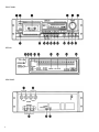
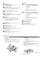
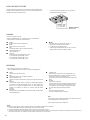
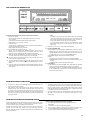
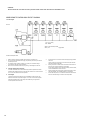
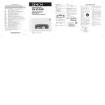
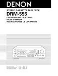
STEREO CASSETTE TAPE DECK
DN-790R
OPERATING INSTRUCTIONS
IMPORTANT TO SAFETY
FOR U.S.A. & CANADA MODEL ONLY
CAUTION
WARNING:
TO PREVENT FIRE OR SHOCK HAZARD, DO NOT EXPOSE THIS
APPLIANCE TO RAIN OR MOISTURE.
TO PREVENT ELECTRIC SHOCK DO NOT USE THIS (POLARIZED) PLUG WITH
AN EXTENSION CORD, RECEPTACLE OR OTHER OUTLET UNLESS THE BLADES
CAN BE FULLY INSERTED TO PREVENT BLADE EXPOSURE.
CAUTION:
1.
Handle the power supply cord carefully
Do not damage or deform the power supply cord. If it is damaged or
deformed, it may cause electric shock or malfunction when used. When
removing it from wall outlet, be sure to remove by holding the plug attachment
and not by pulling the cord.
2.
Do not open the top cover In order to prevent electric shock, do not open
the top cover. If problems occur, contact your DENON DEALER.
3.
Do not place anything inside Do not place metal objects or spill liquid inside
the cassette tape deck. Electric shock or malfunction may result.
Please, record and retain the Model name and serial number of your set
shown on the rating label.
Model No. DN-790R
Serial No.______________________
2
FRONT PANEL
DISPLAY
REAR PANEL
3
DENON SERVICE NETWORK
Please contact one of our overseas service centers, listed below, for follow-up service consultation.
Wenden Sie sich für anfallende Wartungs-bzw. Reparaturarbeiten bitte an eine der folgend aufgeführten Kundendienststellen.
Adressez-vous à nos centres de service d’outre-mer indiqués ci-dessous, pour le service aprèsvente.
Per il servizio dopo vendita rivolgete Vi al nostro centro di servizio estero appropriato della lista seguente.
Para consultas de servicio porfavor dírigirse a cualquiera de nuestros centros de servicio en el extranjero, enlistados abajo.
Neem kontakt op met één van onze reparatie-inrichtingen in het buitenland, waarvan hier een lijst volgt, voor na-service.
Ta kontakt med nedan angivna servicecentraler för rådfrågning om servicearbeten efter försäljningen.
Favor contactar um de nossos centros de serviços internacionais, abaixo listados, para consulta de serviços de acompanhamento.
Australia
Austria
Belgium
Canada
China
Czecho
Denmark
Finland
France
F.R. Germany
Greece
Hong Kong
Iceland
Indonesia
Italy
Korea
Malaysia
Mexico
Netherlands
New Zealand
Norway
Poland
Portugal
Singapore
Spain
Sweden
Switzerland
Taiwan R.O.C.
Thailand
United
Kingdom & Eire
U.S.A.
AWA Audio Products Pty Ltd. 67 O’Riordan Street, Alexandria NSW 2015, Australia
Tel: (02) 9669-3477 Fax: (02) 9578-0140
Digital-Professional-Audio Vertriebsges.m.b.H., 1170 Wien, Rupertusplatz 3
Tel: 0222-4501006~9, Fax: 0222-457679
Transtel-Sabima P.V.B.A. Harmoniestraat 13, 2018 Antwerpen 1, België Tel: 03-237-3607
Denon Canada Inc. 17 Denison Street, Markham Ontario, Canada L3R 1B5 Tel: 905-475-4085 Fax: 905-475-4159
Shanghai Denon Products Service Co., Ltd. Room 1504, A Building 527 Huaihai Zhong Road,
Shanghai 200020, P.R.C. Tel: (021)53062078
EUROSTAR OSTORAVA s.r.o. Za Vokovikou vozovnou 369/5, 161 00 Praha 6
Tel: 2-316-3690 Fax: 2-316-6852
Hifi Klubben A/S Dali Alle 1, 9610 Noerager, Denmark Tel: 45-96 72 10 00 Fax: 45-96 72 10 14
Suomen Hi-Fi Klubi OY Nylandsgatan 4-6, Helsingfors Tel: 0644401
Denon France S.A. 3 Boulevard Ney, 75018 Paris Tel: 44-89-68-69
Denon Electronic GmbH Halskestraße 32, 40880 Ratingen Tel: 02102-4985-0
KINOTECHNIKI LTD. 47 Stournara Str., Athens Tel: 380-6998
Denon Hong Kong Ltd., 11/F North, Somerset House 979 King’s Road, Quarry Bay, Hong Kong
Tel: 2516-6862, Fax: 2516-5940
Japis Ltd. Brautarholt 2, Box 396, 121 Reykjavik, Iceland Tel: 5625200
PT Autoaccindo Jaya. Cideng Barat No. 7 Jakarta, Indonesia Tel: 633-2730
Professional Equipment srl. 20142 Milano v.le Famagosta 37, Italy Tel: 02-89.10.241 Fax:02-81.38.032
DAIYOUNG Industrial Co.,Ltd. 1027-5, Bangbae-dong, Seocho-gu, Seoul 137-060 Korea
Tel: 02-588-3960 Fax: 02-586-3721
Pertama Audio (PJ) Sdn. Bhd. 38, 40 & 42 Jalan PJS 11/28A Sunway Metro Bandar Sunway 46510
Selangor, Malaysia Tel: 03-7378888 Fax: 03-7378188
Labrador, S.A. de C.V. Zamora No. 154 Col. Condesa 06140 Mexico, D.F. Tel: 286 55 09 Fax: 286 34 62
Penhold B.V. Poppenbouwing 58, NL-4191 NZ Geldermalsen, Netherland Tel: 31-345-588 080 Fax: 31-345-588 085
Avalon Audio Corpn. Limited 119 Wellesley Street, Auckland 1, New Zealand Tel: 09-779-351, 09-775-370
Hi-Fi Klubben Box 70 Ankertorget, 0133 Oslo 1 Tel: 02-112218
HORN DISTRIBUTION ul. Nowoursynowska 131R (wjazd od ul. Rosota) 02-975 Warszawa
Tel: 22-649-3071 Fax: 22-649-3199
Videoacustica Qta. Do Paizinho-Armazém 5-Estrada De Circunvalação-Apart. 3127 1303 Lisboa Codex
Tel: 2187004/2187096
Denon Electronics Singapore Pte Ltd. 257 Selegie Road #03-257 Selegie Complex
Singapore 188350 Tel: 65-339-1181 Fax: 65-339-8366
Gaplasa S.A. Conde de Torroja, 25, 28022 Madrid Tel: 91-329-42-63
Sveriges Hi-Fi Klubb Box 5116, S-402 23 Göteborg Tel: 031-200040
Diethelm & Co., AG. Grindelstrasse 5, 8303 Bassersdorf Tel: 01-838-1611
Taiwan Kolin Co., Ltd. 10th Fl., 86, Sec. 1, Chung-king S. Rd., Taipei, Taiwan R.O.C.
Tel: (02) 314-3151 (20 Lines) Fax: (886) 02-3614037 Telex: 11102 TKOLIN
WARNING:
CAUTION:
1. Handle the power supply cord carefully
Do not damage or deform the power supply cord. If it is damaged or
deformed, it may cause electric shock or malfunction when used. When
removing from wall outlet, be sure to remove by holding the plug
attachment and not by pulling the cord.
2. Do not open the top cover
In order to prevent electric shock, do not open the top cover.
If problems occur, contact your DENON dealer.
3. Do not place anything inside
Do not place metal objects or spill liquid inside the CD player.
Electric shock or malfunction may result.
DN - C630
OPERATING INSTRUCTIONS
BEDIENUNGSANLEITUNG
MODE D’EMPLOI
INSTRUCCIONES DE OPERACION
BRUKSANVISNING
Please, record and retain the Model name and serial number of your set
shown on the rating label.
Model No. DN-C630
Serial No.
CAUTION
RISK OF ELECTRIC SHOCK
DO NOT OPEN
CAUTION: TO REDUCE THE RISK OF ELECTRIC SHOCK,
DO NOT REMOVE COVER (OR BACK). NO
USER-SERVICEABLE PARTS INSIDE. REFER
SERVICING TO QUALIFIED SERVICE
PERSONNEL.
The lightning flash with arrowhead symbol, within
an equilateral triangle, is intended to alert the
user to the presence of uninsulated “dangerous
voltage” within the product’s enclosure that may
be of sufficient magnitude to constitute a risk of
electric shock to persons.
The exclamation point within an equilateral
triangle is intended to alert the user to the
presence of important operating and maintenance
(servicing) instructions in the literature
accompanying the appliance.
• FOR U.S.A. & CANADA MODEL ONLY
THIS PRODUCT COMPLIES WITH DHHS RULES 21 CFR
SUBCHAPTER JAPPLICABLE AT DATE OF MANUFACTURE.
CAUTION:
USE OF CONTROLS OR ADJUSTMENTS OR REFORMANCE OF PROCEDURES OTHER THAN THOSE SPECIFIED HEREIN MAY RESULT IN HAZARDOUS RADIATION EXPOSURE.
THE COMPACT DISC PLAYER SHOULD NOT BE ADJUSTED OR
REPAIRED BY ANYONE EXCEPT PROPERLY QUALIFIED SERVICE
PERSONNEL.
This device complies with Part 15 of the FCC Rules. Operation is
subject to the following two conditions : (1) This device may not
cause harmful interference, and (2) this device must accept any
interference received, including interference that may cause
undesired operation.
POWER
OPEN / CLOSE
TRACK
PHONES
If there is no service center in your local area, consult the outlet where the equipment was purchased.
Falls sich in Ihrer Nähe keine Kundendienststelle befindet, wenden Sie sich an das Geschäft, wo das Gerät gekauft wurde.
S’il n’y a aucun centre de service dans votre région, consultez votre revendeur.
Se nella Vostra zona non c’è il centro di servizio, rivolgete Vi al negozio dove avete acquistato l’apparecchio.
Si no hay centros de servicio en su área local, consulte en donde haya comprado su equipo.
Als er in uw streek geen reparatie-inrichting is, neemt u kontakt op met de vestiging waar u de apparatuur gekocht heeft.
Saknas servicecentral i närheten där du bor, bör kontakt tas medåterförsäljaren för apparaten.
Se não existir um centro de serviços em sua área local, consulte o estabelecimento onde o equipamento foi adquirido.
TO PREVENT ELECTRIC SHOCK DO NOT USE THIS (POLARIZED)
PLUG WITH AN EXTENSION CORD, RECEPTACLE OR OTHER
OUTLET UNLESS THE BLADES CAN BE FULLY INSERTED TO
PREVENT BLADE EXPOSURE.
COMPACT DISC PLAYER DN-C630
LEVEL
STOP
CUE
TIME
REPEAT
PLAY
MODE
SINGLE
0%
END MON
INDEX
MIN
REPEAT
A-B
PROG.PLAY
ON / OFF
PROG. IN
PITCH
PLAY / PAUSE
1.
Read Instructions – All the safety and operating
instructions should be read before the applicance is
operated.
2.
Retain Instructions – The safety and operating instructions
should be retained for future reference.
3.
12.
Power-Cord Protection – Power-supply cords should be
routed so that they are not likely to be walked on or
pinched by items placed upon or against them, paying
particular attention to cords at plugs, convenience
receptacles, and the point where they exit from the
appliance.
Heed Warning – All warnings on the applicance and in the
operating instructions should be adhered to.
14.
Cleaning – The appliance should be cleaned only as
recommended by the manufacturer.
4.
Following Instructions – All opeerating and use instructions
should be followed.
15.
Power Lines – An outdoor antenna should be located away
from power lines.
5.
Water and Moisture – The appliance should not be used
near water – for example, near a bathtub, washbbowl,
kitchen sink, laundry tub, in a wet basement, or near a
swimming pool, and the like.
16.
6.
Carts and Stands – The appliance should be used only with
a cart or stand that is recommended by the manufacturer.
6A.
An appliance and cart
combination should be
moved with care.
Quick stops, excessive
force, and uneven
surfaces may cause
the applicance and cart
combination to overturn.
Outdoor Antenna Grounding – If an outside antenna is
connected to the receiver, be sure the antenna system is
grounded so as to provide some protection against voltage
surges and built-up static charges. Article 810 of the
National Electrical Code, ANSI/NFPA 70, provides
information with regard to proper grounding of the mast
and supporting structure, grounding of the lead-in wire to
an antenna-discharge unit, size of grounding conductors,
location of antenna-discharge unit, connection to grounding
electrodes, and requirements for the grounding electrode.
See Figure A.
17.
Nonuse Periods – The power cord of the appliance should
be unplugged from the outlet when left unused for a long
period of time.
This Class B digital apparatus meets all requirements of the
Canadian Interference-Causing Equipment Regulations.
Cet appareil numérique de la classe B respecte toutes les
exigences du Règlement sur le matériel brouilleur du Canada.
CLASS 1 LASER PRODUCT
LUOKAN 1 LASERLAITE
KLASS 1 LASERAPPARAT
7.
Wall or Ceiling Mounting – The appliance should be
mounted to a wall or ceiling only as recommended by the
manufacturer.
18.
Object and Liquid Entry – Care should be taken so that
objects do not fall and liquids are not spilled into the
enclosure through openings.
8.
Ventilation – The appliance should be situated so that its
location or position does not interfere with its proper
ventilation. For example, the appliance should not be
situated on a bed, sofa, rug, or similar surface that may
block the ventilation openings; or, placed in a built-in
installation, such as a bookcase or cabinet that may
impede the flow of air through the ventilation openings.
19.
Damage Requiring Service – The appliance should be
serviced by qualified service personnel when:
CLASS 1
,,
LASER PRODUCT
ADVARSEL: USYNLIG LASERSTRÅLING VED ÅBNING, NÅR
SIKKERHEDSAFBRYDERE ER UDE AF FUNKTION.
UNDGÅ UDSAETTELSE FOR STRÅLING.
VAROITUS!
LAITTEEN KÄYTTÄMINEN MUULLA KUIN TÄSSÄ
KÄYTTÖOHJEESSA MAINITULLA TAVALLA SAATTAA
ALTISTAA KÄYTTÄJÄN TURVALLISUUSLUOKAN 1
YLITTÄVÄLLE NÄKYMÄMTTÖMÄLLE LASERSÄTEILYLLE.
VARNING–
OM APPARATEN ANVÄNDS PÅ ANNAT SÄTT ÄN I
DENNA
BRUKSANVISNING SPECIFICERATS, KAN ANVÄNDAREN
UTSÄTTAS FÖR OSYNLIG LASERSTRÅLNING SOM
ÖVERSKRIDER GRÄNSEN FÖR LASERKLASS 1.
CAUTION
Mahajak Development Co., Ltd. 6th Fl., Mahajak Building, 46 Sukhumvit 3 (Nananua), Klongteoy,
Prakranong, Bangkok 10110 Tel: 256-0020
Hayden Laboratories Ltd. Hayden House, Chiltern Hill, Chalfont St.
Peter Gerrards Cross, Bucks, SL9 9UG Tel: 01753-888447
DENON ELECTRONICS, a Division of Deonon Corporation (U.S.A.) 222 New Road Parsippany,
NJ07054, U.S.A., Tel: 973-575-7810, Fax: 973-575-1213
SEARCH
*
*
*
*
*
*
*
*
*
CERTIFICATION
TO PREVENT FIRE OR SHOCK HAZARD, DO NOT EXPOSE THIS
APPLIANCE TO RAIN OR MOISTURE.
CD PLAYER
SAFETY INSTRUCTIONS
LABELS (for U.S.A. model only)
,,
•
•
•
•
•
•
•
•
IMPORTANT TO SAFETY
9.
Heat – The appliance should be situated away from heat
sources such as radiators, heat registers, stoves, or other
appliances (including amplifiers) that produce heat.
10.
Power Sources – The appliance should be connected to a
power supply only of the type described in the operating
instructions or as marked on the appliance.
11.
Grounding or Polarization – Precautions should be taken so
that the grounding or polarization means of an appliance is
not defeated.
FIGURE A
EXAMPLE OF ANTENNA GROUNDING
AS PER NATIONAL
ELECTRICAL CODE
• POUR LES MODELES AMERICAINS ET CANADIENS
UNIQUEMENT
MAX
PRESET
14-14, AKASAKA 4-CHOME, MINATO-KU, TOKYO 107-8011, JAPAN
Telephone: (03) 3584-8111
Cable: NIPPON COLUMBIA TOKYO Telex: JAPANOLA J22591
Printed in Japan 511 3345 000
808
PAGE
SEITE
PAGE
PAGINA
SIDA
007 ~ PAGE
026 ~ SEITE
046 ~ PAGE
066 ~ PAGINA
086 ~ SIDA
025
045
065
085
105
ELECTRIC
SERVICE
EQUIPMENT
D. The appliance does not appear to operate normally or
exhibits a marked change in performance; or
E. The appliance has been dropped, or the enclosure
damaged.
20.
Servicing – The user should not attempt to service the
appliance beyond that described in the operating
instructions. All other servicing should be referred to
qualified service personnel.
ANTENNA
LEAD IN
WIRE
GROUNDING CONDUCTORS
(NEC SECTION 810-21)
GROUND CLAMPS
POWER SERVICE GROUNDING
ELECTRODE SYSTEM
(NEC ART 250, PART H)
NOTE:
This CD player uses the semiconductor laser. To allow you to enjoy music at a
stable operation, it is recommended to use this in a room of 5 °C (41 °F) – 35
°C (95 °F).
1
C. The appliance has been exposed to rain; or
ANTENNA
DISCHARGE UNIT
(NEC SECTION 810-20)
POUR PREVENIR LES CHOCS ELECTRIQUES NE PAS UTILISER
CETTE FICHE POLARISEE AVEC UN PROLONGATEUR UNE PRISE
DE COURANT OU UNE AUTRE SORTIE DE COURANT, SAUF SI LES
LAMES PEUVENT ETRE INSEREES A FOND SANS EN LAISSER
AUCUNE PARTIE A DECOUVERT.
FOR ENGLISH READERS
FÜR DEUTSCHE LESER
POUR LES LECTEURS FRANCAIS
PARA LECTORES DE ESPAÑOL
FÖR SVENSKA LÄSARE
B. Objects have fallen, or liquid has been spilled into the
appliance; or
GROUND
CLAMP
ATTENTION
G80801
A. The power-supply cord or the plug has been damaged;
or
NEC - NATIONAL ELECTRICAL CODE
2
4
NOTE ON USE
Keep the set free from moisture,
water, and dust.
Do not let foreign objects in the set.
Avoid high temperatures
Allow for sufficient heat dispersion
when installed on a rack.
Unplug the power cord when not
using the set for long periods of time.
Do not let insecticides, benzene, and
thinner come in contact with the set.
Handle the power cord carefully. Hold
the plug when unplugging the cord.
"(For sets with ventilation holes)
Do not obstruct the ventilation holes.
Never disassemble or modify the set
in any way.
5
Thank you very much for purchasing the DENON component stereo
cassette tape deck.
DENON proudly presents this advanced tape deck to audiophiles and
music lovers as a further proof of DENON's non compromising pursuit
of the ultimate in sound quality. The high quality performance and
easy operation are certain to provide you with many hours of
outstanding listening pleasure.
- TABLE OF CONTENTS FEATURES ..............................................................6
CONNECTION .........................................................7
NAMES AND FUNCTION OF PARTS..........................8, 9
CASSETTE TAPES ....................................................9
AUTO TAPE SELECT FEATURE ................................10
PLAYBACK .............................................................10
RECORDING ..........................................................10
AUTOTUNING ........................................................11
MONITOR BUTTON ................................................11
PROPER RECORDING LEVEL ...................................12
RECORDING BIAS ADJUSTMENT .............................12
REC/REC MUTE BUTTON ........................................12
MUSIC SEARCH SYSTEM ........................................12
TAPE COUNTER AND MEMORY STOP ......................13
DOLBY NOISE REDUCTION SYSTEM .......................13
DOLBY HX-PRO HEADROOM EXTENSION SYSTEM ...13
WIRED REMOTE CONTROL BOX CIRCUIT DIAGRAM 14
MAINTENANCE ......................................................15
TROUBLESHOOTING ..............................................16
SPECIFICATIONS ...................................................16
6
Please check to make sure the following items are
included with the main unit in the carton:
(1) Operating Instructions……………………………………………………… 1
(2) Connection Cords …………………………………………………………….. 2
FEATURES
•
•
•
•
•
•
•
•
•
•
•
•
•
•
•
•
Computer Controlled Mechanism
Closed-loop Dual-capstan Tape Transport
Non-slip Reel Drive for Stabilizing Tape Tension
Dual Power Supply
3-Head Design Utilizes The Amorphous Head
Dolby S Noise Reduction System
Dolby HX PRO System
Dolby B & C Noise Reduction System
XLR Type (Balanced) Input/Output Connectors Provided
Auto Tuning
Manual Bias Adjustment Controls
Computing Linear or Real Time Tape Counter With 4-Digit
Read out and Memory Stop
Auto Tape Selector.
19-inch Rack Mountable
Speed Control of Approximately ±12%
Accurate Music Search System
CONNECTION
• Leave your entire system (including this cassette deck) turned off until all connections between the deck and other components have been completed.
• Connecting the Deck to an Amplifier
Before connecting the deck to your amplifier, it is a good practice to review your
amplifier's instruction manual.
Use the white plugs for the left channel and red plugs for the right channel.
• Systems Remote Control (Refer to page 14)
A wired remote control box can be connected to this unit. No remote control
box is included. For remote control, the user should build a remote control box
referring to the schematic diagram (remote control box schematic diagram).
Connect the remote control terminal to the remote control jack on the rear
panel.
• Connecting Headphones
To listen through headphones, plug your headphones into the PHONES jack.
• Tape Dubbing
Many stereo amplifiers and receivers have tape dubbing circuitry so that tape
duplication can be performed between two or more tape decks. Review your
amplifier's instruction manual for a full explanation of this mode of operation.
• Installation Precautions
If the deck is placed near an amplifier, tuner or other components, noise
(induced hum) or beat interference may result (especially during AM or FM
reception). If this occurs, separate the deck from other components or reorient
its position.
NOTE:
Use this unit in a horizontal orientation.
When the unit is used with the front panel facing upward (and the unit is in a
vertical orientation) or when the front panel is on an incline, the unit will not operate
properly.
7
NAMES AND FUNCTIONS OF PARTS (Refer to Page3.)
FRONT PANEL
Power Switch (POWER)
TAPE SIZE button
Controls the supply of AC power to the deck. One push turns the deck on, a second
push turns it off. The deck remains in a stand-by (non-operative) mode for
You can know accurate elapsed time of the tape by adjusting the
TAPE SIZE button to the tape size used. When the TAPE SIZE button is pressed, the
approximately 2 seconds after it is switched on.
current tape size is displayed for 1 sec in the 4-figures counter. If you further press
the button during the display, the tape size will change in the following cycle.
C-90---C-74--C-60--C-100 --C-90 …etc
EJECT button
Press this button to eject the cassette. When the deck is operating (tape is
running), press the stop button first to stop the tape transport; then press the
EJECT button.
Cassette compartment cover
If this compartment cover is not closed completely, the deck's transport controls will
remain inoperative.
Auto Tuning, CLEAR button (CLEAR)
When this button is pressed after-setting auto tuning or during the auto tuning
operation, auto tuning is cleared and the recording characteristics are reset to the
standard values. Refer to page 11.
MONITOR button
Auto Tuning START button (START)
The SOURCE position of this button allows you to monitor the source program
before it is recorded. The TAPE position of this button is used for tape playback
When this button is pressed, the auto tuning operation starts and the recording
characteristics most suited for the tape being used are set automatically. Refer to
monitoring or simultaneous monitoring during recording.
page 11.
MPX FILTER button
REC LEVEL control
The recording input level is adjusted by this knob. The levels in the left and right
channels can be changed independently.
The MPX FILTER button should be used to prevent interference with the Dolby NR
circuit when making Dolby NR encoded recordings '6f FM stereo programs. When
making Dolby NR encoded recordings from any program source other than FM
stereo, leave this button in the "OFF" position.
TAPE SPEED button
This button is for setting the tape speed to the fixed speed (FIX) or variable speed
(VARIABLE) position.
When set at the FIX position, the tape is played at the standard (fixed) speed
regardless of the position of the tape speed control knob.
When set at the VARIABLE position, the tape speed changes according to the
position of the tape speed control knob.
There are independent buttons for the Dolby NR "OFF", "B", "C" and "S" positions.
When recording tapes, set the Dolby NR function as desired.
When playing tapes, set the Dolby NR function to the same position as when the
tape was recorded.
PHONES jack
BIAS FINE control
For private music enjoyment without disturbing others, or for monitoring a
recording, a set of headphones may be plugged in. Impedance should be from 8 to
1200 ohms.
(for NORMAL, Cr02 and METAL tape)
Adjust the bias according to the tape characteristics. Standard biasing is obtained at
the center click-stop position.
COUNTER RESET button
TAPE SPEED control
(for the real time counter and the linear counter too) Operation of the
button resets the counter to all zero.
Use this knob to vary the tape speed.
First set the tape speed button to the VARIABLE position.
The speed can be varied within a range of approximately ±12% according to the
position of the tape speed control knob.
MEMORY STOP button
During rewinding operations, the tape will stop at the "00 00" counter point
automatically when this button is pressed in.
17. Tape transport controls
8
DOLBY NR switch
DISPLAY
REAR PANEL
XLR Type input connectors (BALANCED INPUT)
TAPE SPEED indicator
"FIX" or "VARIABLE" is interlocked with the TAPE SPEED button. The tape speed
can be controlled when "VARIABLE" is light.
a)
AUTO TUNING indicator
b)
This indicator flashes during the auto tuning operation and stops flashing,
remaining lit, once auto tuning is completed. The indicator turns off when the
CLEAR button is pressed, and when the auto tuning data is cleared.
c)
These are active balanced inputs using XLR type connectors
(XLR-3-31). Connected them to the balanced output terminals on an
amplifier or console.
Pin layout:
Pin 1 – Common
Pin 2 – Cold
Pin 3 - Hot
Applicable connector: XLR-3-12C or the equivalent.
NOTE: Do not short-circuit the hot or cold pin with the common pin.
PLAY, PAUSE and REC indicator
When the PLAY, PAUSE and REC buttons are pressed, this indicator will light.
XLR Type output connectors (BALANCED OUTPUT)
a)
Fluorescent peak meters
These meters indicate recording or playback peak levels for each channel. For peak
levels exceeding -7 dB, the Auto Peak Hold Feature holds the peak level reading for
b)
approximately 1 seconds.
Tape counter
c)
Tape-passage is indicated digitally in minutes and seconds.
When "M" and "S" are lit, the counter is set to the real time display mode.
These are active balanced outputs using XLR type connectors
(XLR-3-32). Connected them to the balanced input terminals on an
amplifier or console.
b) Pin layout:
Pin 1 - Common
Pin 2 - Cold
Pin 3 - Hot
Applicable connector: XLR-3-11C or the equivalent.
NOTE: Do not short-circuit the hot or cold pin with the common pin.
When "M" and "S" are off, the counter is set to the linear display mode.
For an explanation of the real time and linear time display modes, refer to the
section "TAPE COUNTER AND MEMORY STOP".
RCA Pin Jack (UNBALANCED)
INPUT Selector switch
Use this to select the input jack to be used.
MEMORY indicator
Remote Control Jack
This indicator light is interlocked with the memory stop button. (MEMORY)
Use this to operate the DN-790R using the remote control box.
(The remote control box is not included with the DN-790R.)
MPX FILTER indicator
This indicator light is interlocked with the MPX FILTER button.
TAPE SELECT indicator
This indicator light is interlocked with the Auto Tape Select feature which
automatically adjusts the deck to the type of tape in use.
(TYPE I TYPE II or TYPE IV).
MONITOR indicator
This indicator light is interlocked with the MONITOR button to inform the use of the
selected monitoring source TAPE or SOURCE.
CASSETTE TAPES
•
•
Handling Precautions
C-120 Cassettes:
•
C-120 cassette tapes are not recommended as they use a very thin tape base
which may become tangled around the capstan or pinchroller.
Tape Slack:
This cassette deck incorporates an automatic tape slackness preventive
mechanism, but it can not prevent such a slackness as shown below. Remove it
with a pencil or the like prior to use.
• Storage Precautions
• Do not store cassette tapes in -a place where they will be subject to:
•
Extremely high temperature or excessive moisture
•
Excessive dust
•
•
Direct sunlight
•
Magnetic fields (near TV sets or speakers)
To eliminate tape slack, store your cassettes in cassette cases with hub stops
• Accidental Erasure Prevention
• Every cassette has erasure prevention tabs for each side. To protect your valuable
recorded tapes from accidental or inadvertent erasure, remove the tab for the
•
appropriate side with a screwdriver or other tools.
To record on a tape with the erasure prevention tabs removed, cover the tab holes
with plastic tape.
9
AUTO TAPE SELECT FEATURE
This Stereo Cassette Deck contains an Auto Tape Select feature which automatically selects
the optimum bias and equalization for the tape in use. This is accomplished by detection of
tape type detection holes in the cassette housing.
•
If a tape without tape type detection holes is used, the deck will
automatically adjust itself for normal tapes.
PLAYBACK
• Switch on your amplifier or receiver.
• Set the TAPE MONITOR switch on your amplifier or receiver to the TAPE position.
• Operate the deck in numerical order as illustrated below:
►PLAY
PHONES
Playback sound is fed into the headphones set.
POWER
Push the switch to turn "ON" the power.
EJECT
Press the EJECT button to open the cassette compartment.
Cassette Compartment Cover
Load the cassette tape
DOLBY NR
For recordings made without Dolby NR, set to "OFF".
For recordings made with Dolby B NR, set to "B".
For recordings made with Dolby C NR, set to "C".
For recordings made with Dolby S NR, set to "S".
•
•
•
Push the PLAY button (The PLAY indicator will light up).
When playback is finished, press the stop button.
To restart the tape, press the PLAY button.
If different types of Dolby Noise Reduction are used for record and
playback, playback response will be adversely effected.
.
RECORDING
• Switch on the source component (tuner, amplifier, etc.).
• Set the TAPE MONITOR switch on your amplifier or receiver to the SOURCE position.
POWER
Push the switch to turn "ON" the power.
EJECT
Press the EJECT button to open the cassette compartment.
Cassette Compartment Cover
(Make sure the erasure prevention tab has not been removed from the cassette shell
half.)
DOLBY NR
Set, in accordance with the recording to be made. For recordings without Dolby NR,
• REC/REC MUTE
When pressed, the deck goes into the record standby mode. The O
REC and OV PAUSE indicators ® will light. Initial setting of recording
levels should be made in the record standby mode.
The tape speed control is set to the fixed mode and "FIX" lights on the
display.
REC LEVEL
Used to set the recording level.
The left and right channels can be adjusted independently. Normally
set the grooves in the controls for the left and right channels to the
set to "OFF". For recordings with Dolby B NR, set to "B". For recordings with Dolby C
NR, set to "C". For recordings with Dolby S NR, set to "S". Future mistakes during
same positions. To change the left/right recording balance, operate
the controls for the left and right channels separately.
(PLAY
playback can be avoided if the cassette is so marked for Dolby NR encoded
recordings.
MPX FILTER
Button 13 it "ON" for the DOLBY NR recording of FM broadcasts (The MPX FILTER
indicator 24 will light up).
When pressed, the recording will start.
(The >PLAY and OREC indicators ® will light up).
Note:
In the recording mode, the variable speed mode cannot be selected, and the mode
is automatically switched to the fixed speed mode.
•
When recording is finished, press the STOP button.
Caution:
Be careful not to erase important recordings by mistake. Mis-erasing can be avoided by following the two steps below:
1. If the PLAY button (17) is pressed while the REC indicator is on, the tape will be recorded.
2. If the PLAY and RECORD (*REC) button (17) are pressed at the same time, the tape will be recorded.
3.
10
Performing the record pause or the stop operation during recording will create a discontinuous portion in the recording signal. The previously recorded signal may remain after erasure at
this connecting portion. Also, a very small amount of the end portion of the previous song may be erased.
AUTO TUNING
Though tapes may be of the same type, tapes of different manufacturers and even tapes of the same manufacturer may have slightly different recording characteristics. The auto tuning system
is a function which automatically sets the optimum recording characteristics to take maximum advantage of the performance of individual tapes.
Set the cassette tape to be tuned into the cassette box.
Set the Dolby NR switch for the position to be used for recording.
Caution:
1.
Press the 0 REC/REC MUTE button to set the recording pause mode.
(The " O " Rec and “ll” PAUSE indicators will light up.)
Press the START button. Tuning starts. The AUTO TUNING indicator flashes during
tuning.
2.
After 5 to 10 seconds, tuning is completed, the tape is automatically rewind to a
position a little before the position at which tuning started, and the AUTO TUNING
rewound to a position a little before the beginning of the magnetic portion (at the
leader tape section) after tuning is completed.
indicator stops flashing, remaining lit.
To cancel the setting:
During tuning:
Press the STOP or CLEAR button.
After tuning:
Press the CLEAR button.
Turn off the power.
The recording characteristics are reset to the standard values.
Note: To achieve the optimum recording characteristics, we recommend always tuning
each tape before recording, even for tapes of the same type and the same
manufacturer.
If tuning is started from the beginning of the tape (the leader tape section), tuning is
performed after the tape is forwarded to the magnetic portion. In this case, the tape is
3.
If the tape is too near the end, the tuning mode may be canceled before tuning is
completed.
4.
The bias control knob on the front panel functions during auto tuning, so we
recommend setting it to the center click position. If the bias control knob is set too far
in one direction, the auto tuning system may not be able to fully correct the change in
the frequency response and level, resulting in poor recording characteristics.
MONITOR BUTTON
This Stereo cassette deck uses a three-head system which permits simultaneous "off-the-tape monitoring" during recording.
11
PROPER RECORDING LEVEL
A too high recording level can saturate the tape and cause distortion. On the other hand, if the recording levels are set too low, soft passages will be marked by residual noise. Proper recording
level is the single most important factor for making well balanced recordings.
Guideline for maximum recording level
Normal tape
Cr02 tape
Metal tape
TYPE 1
TYPE II
TYPE IV
+1 dB levels on peaks
+3 dB levels on peaks
+5 dB levels on peaks
Note:
Optimum recording levels can differ depending on program sources or the type of tape used.
RECORDING BIAS ADJUSTMENT
•
Use this to change the characteristics to suit your tastes, taking advantage of the
performance of the tape.
•
For normal recording, set the control at the center click position to achieve
satisfactory characteristics.
If the bias is low (when the knob is turned to the " - " side), the high frequencies
•
Caution:
The bias control knob functions independently of the auto tuning system, so if it is adjusted
after auto tuning, the bias changes starting from a flat recording characteristic.
increase, but so does distortion. If the bias is high, (when the knob is turned to
the " + " side), the high frequencies decrease, but so does distortion.
REC/REC MUTE BUTTON
REC/REC MUTE is the DENON's unique and convenient function. By using this button, it is
easily possible to insert a suitable space (the non-recorded part) between two melodies.
1. When you want to make about 5 seconds of non-recorded part after the
recording state:
Press the REC/REC MUTE button. The recorder will automatically create about 5
seconds of non-recorded part and will stay in the recording standby state.
2. To create about 5 seconds of non-recorded part after the standby state: Press the
REC/REC MUTE button, and the recorder will enter the non-recording state,
automatically create about 5 seconds of non-recorded part and stay in the standby
state.
3.
4.
To cancel the non-recording state (the REC MUTE state): Press the PAUSE button, and
the recorder will cancel the non-recording state and will stay in the standby state.
To extend the non-recording state (the REC MUTE state) for further 5 seconds or more:
Press the REC/REC MUTE button, and the non-recorded part will automatically be
extended for another 5 seconds.
MUSIC SEARCH SYSTEM
This device is a convenient system which detects the non-recorded part of more than 4
seconds between melodies, cues the next melody while the present melody is being
reproduced or automatically detects the beginning of the melody now being reproduced and
makes it into the reproduceable state.
1.
For cueing the next melody while the present melody is being reproduced:
At PLAY mode, depress the PLAY button and the FF button simultaneously. This device
2.
will detect the interval between melodies with the CUE state on, automatically become
the PLAY mode and begin performing the next melody.
For hearing again the melody being reproduced:
At PLAY mode, depress the PLAY button and the REW button simultaneously. This
device will detect the interval between melodies with the REVIEW state on,
automatically become the PLAY mode, detect the beginning of the melody now being
performed and play it from the first again.
12
NOTE: Note about MUSIC SEARCH action:
MUSIC SEARCH is a function which operates by detecting a comparatively
long non-recorded part on the tape. Therefore, MUSIC SEARCH may not
operate normally in the following cases.
• Sound on the tape is interrupted by speech or conversation.
•
•
Long periods of pianissimo (Softly played music) or non-recorded intervals occur on the
tape.
The tape has picked up noise in a non-recorded interval.
•
•
Non-recorded intervals on the tape are less than 4 seconds in length.
Noise-emitting electrical appliances are in operation nearby, i.e.;
Electric razors, drills, refrigerators, etc.
TAPE COUNTER AND MEMORY STOP
• Note
The method of measuring the time and the precision differ for the real time tape
counter (fixed speed travel) and the linear tape counter. The tape may not be
1) Operation of the Real Time Tape Counter and the Linear Tape Counter
• Real Time Tape Counter
The time of the tape traveling at a constant speed is indicated in "M" (minutes)
•
(1)
(2)
(3)
and "S" (seconds).
A microcomputer measures and displays the time with high precision.
Display example: 32: 10: 32 minutes, 10 seconds.
Linear Tape Counter
The tape travel time is indicated with a 4-digit value. The first two digits indicate the
minutes, the last two digits the seconds.
Display example: 3456 34 minutes, 56 seconds.
Press the RESET button to reset the counter to:
00: 00:
"M" and "S" are not displayed when "VARIABLE" is displayed. They are also not
displayed when "FIX" is displayed during the fast-forward, rewind, music search
operations or when the STOP button has been pressed during an operation.
Select "FIX" using the TAPE SPEED button. "FIX" appears on the display, the counter
is set to the real time mode, and "M" (minutes) and "S" (seconds) appear.
The counter remains in the real time mode when the play, record play, pause, record
pause or stop mode is selected at this time.
The counter automatically switches to the linear mode if the fast forward or rewind
mode is set from any of the modes in (2)or if the "VARIABLE" mode is set during
playback.
(4) If the music search mode is selected, the counter automatically switches to the linear
mode, then switches back to the real time mode once playback begins after the music
search operation.
(5)
2)
3)
returned to the precise position when the fast-forward, rewind, music search or
memory rewind operations are used, but this is not a malfunction.
Use the real time tape counter to measure the accumulated time at constant
speed without counting the time in which the pause, stop and record pause
modes are set.
The counter is reset to " 00 00 " when the EJECT button is pressed.
Operation of MEMORY STOP
(1) During recording or playback operations, MEMORY STOP can be used to locate a
particular point on the tape. At the desired point, reset the counter to" 00.00.
".With the MEMORY STOP button in the "ON" position, the deck will stop at the "00
00 " point (actually -00 02 " and "00 00 ") during REWIND operations.
(2) The MEMORY indication will light when this function is activated.
(3) Notes:
When the power is turned "OFF", this function is automatically deactivated.
The MEMORY STOP is accurate to -5 on the counter, and will stop between "-00 02
" and "00 00 ".
The MEMORY STOP is released by pressing the EJECT button.
Display Back-up
(1) The DOLBY NR, MPX FILTER, COUNTER VALUE, TAPE SPEED and TAPE SIZE
functions are protected for approximately one month by a memory back-up.
Once the back-up period is up, the DOLBY NR and MPX FILTER settings are set to
off, the TAPE SIZE setting is reset to "C-90", the Tape Speed setting is set to FIX,
and the counter is reset to ”00 00”.
DOLBY NOISE REDUCTION SYSTEM
•
The Dolby noise reduction system substantially reduces the tape background noise
(hiss) inherent in the cassette medium.
•
Tape background noise consists primarily of high frequency information, which is
particularly annoying during soft passages. The Dolby NR system increases the level of
low volume mid and high frequency signal during recording and reduces the level of
these signals by an identical amount during playback. As a result, the playback signal is
identical to the original source signal, but the level of background noise generated by the
•
The operating principle of Dolby C NR is similar to that of Dolby B NR except for the
encoding /decoding response curves. The noise reduction effect obtained with Dolby C
NR is up to 20 dB, compared to 10 dB with Dolby B NR. In addition, Dolby C NR uses
an anti-saturation network and spectral skewing circuitry for a significant improvement
•
tape is greatly reduced.
in the dynamic range of the mid- to high-frequencies.
The S-type provides a maximum noise reduction effect of 24 dB in the high frequencies
and 10 dB in the low frequencies, and expands the dynamic range over a wide
frequency range.
DOLBY HX-PRO HEADROOM EXTENSION SYSTEM
This deck is equipped with the Dolby HX-PRO headroom extension system. Since the system
functions automatically during recording, no switching operation or adjustment is required.
The system is effective with any type of Normal, Cr02 and Metal tape.
The Dolby HX-PRO headroom extension system functions during recording to lift up the
saturation level in the treble range. Therefore, most of the treble range components
distorted or lost during recording on conventional cassette decks are more faithfully recorded
on the new cassette deck.
Features of the Dolby HX-PRO Headroom Extension System
(1)
Performance of Normal and Cr02 tapes can be upgraded closer to that
(2)
(3)
(4)
of Metal tapes.
The dynamic range in the treble is improved significantly.
Since no decoding in playback is necessary, the improvement can be obviously heard
on any hi-fi playback system including portable components and car systems.
The system functions whether the Dolby B/C/S NR is engaged or not.
13
WARNING:
INSTRUCTIONS ON THIS PAGE ARE FOR QUALIFIED SOUND INSTALLERS AND SERVICE PERSONNELS ONLY.
WIRED REMOTE CONTROL BOX CIRCUIT DIAGRAM
1. Circuit Diagram
First Unit
L - CH : Vcc (5 VOLT)
R -CH : SIGNAL
SWO01 - 006: Momentary Contact
SW101, 102:
Toggle Switch
Second and Subsequent Units
•
•
•
•
2.
3.
Make a control box using the supplied remote control box connection wire.
Do not connect the left channel of the plug (Vcc) with 8001 (200 ohms) in the second
and subsequent units.
Use resistors having a tolerance of within ±5% (1/4W). Use of resistors having a
poorer tolerance will cause incorrect operation.
Never short circuit the left-channel line (Vcc). Doing so will damage the main unit.
Operation with Parallel Connections
A number of DN-790R units can be simultaneously operated in parallel with 1 button.
Operation with parallel connections can be used with a maximum of 5 units. Connection
of 6 or more units will lead to incorrect operation.
Cable Length
The longer the length of the cable, the more susceptible the system will be to the
effects of external noise. Keep cable lengths to 2 m or less. Do not locate equipment
that produces electrical noise in the vicinity of the cable. Doing so might lead to
incorrect operation due to the noise.
14
4.
5.
6.
7.
Do not disconnect or connect the remote control plug during operation
of the unit.
The pins of the plug might cause a short circuit of the pins inside the
jack which can stop the operation.
Pressing more than one button of the wired remote control box at the
same time (for combined operations) is not possible.
A music search operation will not result from pressing the PLAY and FF,
or PLAY and REW buttons at the same time.
Pressing a button of the wired remote control box and a button of the
main unit, DN-790R, (for combined operations) is not possible.
Do not switch the power on or off when the cable of the wired remote
control is connected. Doing so will cause incorrect operation.
MAINTENANCE
•
Removing the cassette compartment cover
It will be more convenient if the cassette compartment cover is
removed during the cleaning of the pinchroller and heads, or during
demagnetizing of heads.
Follow these procedures:
1. Press the EJECT button to open the cassette compartment.
2. Hold only the cover of the cassette compartment and pull it up. The
• Cleaning the Pinchroller and the Capstan
If the pinchroller or the capstan accumulate dust, tape transport may become
unstable resulting from slippage during recording or playback. The tape can also be
damaged by being rolled up around the capstan. Clean them with a cotton swab or
soft cloth moistened with cleaning solution (such as alcohol).
compartment cover is removed from the front.
When attaching the cassette compartment cover, reverse the above procedure.
•
Head Cleaning
After long usage, tape coating or dust may adhere to the heads, causing deterioration
of sound. Clean them regularly. Use a cotton swab moistened with cleaning solution
(such as alcohol).
Note:
1. Some cleaning cassettes on the market have a strong abrasive effect
and scratch the heads. Use cotton swab instead of cleaning cassettes.
2. Since the use of metal tapes is apt to collect more dust on the heads,
clean the heads more often to enjoy optimum sound.
• Demagnetizing the Heads
The heads may become magnetized after long usage or by having a strongly
magnetized object brought neat them. The result is a generation of noise, loss of the
high frequency range, or erasing the treble components of pre-recorded tapes and
adding noise.
Demagnetize the heads on a regular basis.
• Procedure
1. Be sure to turn "off" the power supply.
2. Turn the demagnetizer "on" while it is more than 30cm away from the heads.
Bring the demagnetizer near the heads and slowly move it in a small circle four or
five times.
3. Slowly move the demagnetizer away from the heads and turn "off" the power of
the demagnetizer when it is about 30cm away from the heads.
15
TROUBLESHOOTING
Make sure of the followings before you consider as any malfunctions:
1.
Are all the connections correct?
2.
Is the set being operated correctly in accordance with the operating instructions?
3.
Are the speakers and amplifiers functioning correctly?
If the tape deck still does not function properly, check it again, using the check list below. If the symptom does not correspond to the check list, please contact your DENON dealer.
Problem
Tape does not run.
Tape is not recorded when recording button is
pressed.
Sound is warbled or distorted.
Cause
• Power cord is off.
• Tape is completely wound up.
• Tape is loose.
• Cassette is not loaded properly.
• Defective cassette.
• No cassette is loaded.
• Erase prevention tab is broken off.
• Heads, capstan or pinchroller are contaminated
Remedy
• Check power cord.
• Rewind tape.
• Tighten tape with a pencil, etc.
• Load cassette properly.
• Replace cassette.
• Load cassette.
• Cover hole with plastic tape.
• Clean them.
• Tape is wound too tight.
• Fast forward or rewind to loosen tape
winding.
• Adjust recording input level.
• Replace tape.
• Replace tape.
• Clean them.
• Recording input level is too high.
• Tape is worn out and has "drop-outs".
• Tape is worn.
• Heads, capstan or pinchroller are contaminated
Excessive noise.
High frequency (treble) is emphasized.
High frequency (treble) is lost.
When a Cr02 or metal tape is placed in the deck,
a different tape indicator comes on.
The cassette tape cannot be removed.
• Heads are magnetized.
• Recording input level is too low.
• Dolby NR button is set improperly.
• Heads are contaminated.
• Tape is worn.
• The cassette housing is of an older design
without tape type detection holes.
• If the power switch is turned off in either the
recording or playback mode, and the unit is
stopped, there may be case when the
cassette cannot be removed, even if the
EJECT button is pressed.
• Demagnetize heads.
• Adjust recording input level.
• Set Dolby NR button properly.
• Clean them.
• Replace tape.
• Use the latest cassette with tape type detection
holes.
• Turn the power switch ON again, and then
press the stop button.
• Then, in the stop mode, press the EJECT
button to remove the cassette tape.
SPECIFICATIONS
Type
Motors
Vertical tape loading; 4-track 2-channel
stereo cassette deck
Recording head (amorphous) x 1
Playback head (amorphous) x 1
Erase head (Double-gap ferrite) x 1
Capstan (DC servo motor) x 1
Headphone
1.23 V (+4 dBm)
(with 600 ohms load, recorded level of 200 pwb/ mm )
775 mV (0 dBm)
(with 47k ohms load, recorded level of 200 pwb/mm)
1.2 mW output level at maximum
Tape Speed
Reel (DC motor) x 1
Actuator (DC motor) x 1
4.8 cm/sec. (FIX)
Power Supply
Power Consumption
(optimum load impedance 8 ohms ~ 1.2 k ohms)
Voltage is shown on rating label
22 W
Variable (PLAY)
Fast Forward,
Rewind Time
Approx. ±12%
Dimensions
Approx. 100 sec. with a C-60 cassette
Weight
483 (W) x 134 (H) x 275 (D) mm
(19" x 5-17/64" x 10-53/64")
5.1 kg (11 Lbs 11 oz)
Recording Bias
Overall S/N Ratio
(at 3% THD level)
Approx 105 kHz
Installation
19-inch rack mountable (3U)
Heads
Overall Frequency
Response
Channel Separation
Crosstalk
Wow & Flutter
Inputs
RCA Pin Jack
Dolby C NR on: more than 75 d8 (CCIR/ARM)
•
20 ~ 20,000 Hz ±3 dB (at-20 dB, Metal tape)
More than 40 dB (at 1 kHz)
•
More than 65 dB (at 1 kHz)
0.038% WRMS (JIS method), ±0.1 % w. peak
Line XLR Type Connector 1.23 V (+4 dBm) input level at maximum
Input impedance: 200 ohms balanced
RCA Pin Jack
80 mV (-20 dBm) input level at maximum
Input impedance: 50 k ohms unbalanced
16
Outputs:
Line XLR Type Connector
•
Above specifications and design styling are subject to change for
improvement.
Dolby noise reduction and HX Pro headroom extension manufactured
under license from Dolby Laboratories Licensing Corporation. HX Pro
originated by Bang & Olufsen.
"DOLBY", the double-D symbol and "HX PRO" are trademarks of
Dolby Laboratories Licensing Corporation.