1
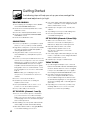
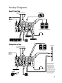
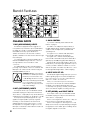
owner’s manual
by
CAUTION
AVIS
RISK OF ELECTRIC SHOCK
DO NOT OPEN
RISQUE DE CHOC ELECTRIQUE
NE PAS OUVRIR
CAUTION: TO REDUCE THE RISK OF ELECTRIC SHOCK
DO NOT REMOVE COVER (OR BACK)
NO USER-SERVICEABLE PARTS INSIDE
REFER SERVICING TO QUALIFIED PERSONNEL
ATTENTION: POUR EVITER LES RISQUES DE CHOC
ELECTRIQUE, NE PAS ENLEVER LE COUVERCLE. AUCUN
ENTRETIEN DE PIECES INTERIEURES PAR L'USAGER. CONFIER
L'ENTRETIEN AU PERSONNEL QUALIFIE.
AVIS: POUR EVITER LES RISQUES D'INCENDIE OU
D'ELECTROCUTION, N'EXPOSEZ PAS CET ARTICLE
A LA PLUIE OU A L'HUMIDITE
The lightning flash with arrowhead symbol within an equilateral
triangle is intended to alert the user to the presence of uninsulated
“dangerous voltage” within the product’s enclosure that may be
of sufficient magnitude to constitute a risk of electric shock to persons.
Le symbole éclair avec point de flèche à l'intérieur d'un triangle
équilatéral est utilisé pour alerter l'utilisateur de la présence à
l'intérieur du coffret de “voltage dangereux” non isolé d'ampleur
suffisante pour constituer un risque d'éléctrocution.
The exclamation point within an equilateral triangle is intended to
alert the user of the presence of important operating and maintenance
(servicing) instructions in the literature accompanying the appliance.
Le point d'exclamation à l'intérieur d'un triangle équilatéral est
employé pour alerter les utilisateurs de la présence d'instructions
importantes pour le fonctionnement et l'entretien (service) dans le
livret d'instruction accompagnant l'appareil.
SAFETY INSTRUCTIONS
1.
Read Instructions — All the safety and operation instructions
should be read before this product is operated.
2.
Retain Instructions — The safety and operating instructions
should be kept for future reference.
3.
Heed Warnings — All warnings on this product and in these
operating instructions should be followed.
4.
Follow Instructions — All operating and other instructions
should be followed.
5.
Water and Moisture — This product should not be used near
water – for example, near a bathtub, washbowl, kitchen sink,
laundry tub, in a wet basement, near a swimming pool, etc.
6.
Cleaning — Clean only with a dry cloth.
7.
Ventilation — This product should be situated so that its location
or position does not interfere with its proper ventilation. For
example, the Component should not be situated on a bed,
sofa, rug, or similar surface that may block any ventilation
openings, or placed in a built-in installation such as a bookcase
or cabinet that may impede the flow of air through ventilation
openings.
8.
Heat — This product should be situated away from heat
sources such as radiators, or other devices which produce
heat.
9.
Power Sources — This product should be connected to a
power supply only of the type described in these operation
instructions or as marked on this product.
12. Damage Requiring Service — This product should be serviced
only by qualified service personnel when:
A. The power-supply cord or the plug has been damaged; or
B. Objects have fallen, or liquid has spilled into this product; or
C. This product has been exposed to rain; or
D. This product does not appear to operate normally or
exhibits a marked change in performance; or
E. This product has been dropped, or its chassis damaged.
13. Servicing — The user should not attempt to service this
product beyond those means described in this operating
manual. All other servicing should be referred to the Tapco
Service Department.
14. To prevent electric shock, do not use this polarized plug with
an extension cord, receptacle or other outlet unless the
blades can be fully inserted to prevent blade exposure.
Pour préevenir les chocs électriques ne pas utiliser cette fiche polariseé avec
un prolongateur, un prise de courant ou une autre sortie de courant, sauf si les
lames peuvent être insérées à fond sans laisser aucune pariie à découvert.
15. Grounding or Polarization — Precautions should be taken so
that the grounding or polarization means of this product is not
defeated.
16. Power Precaution — Unplug this product during lightning
storms or when unused for long periods of time.
17. This apparatus does not exceed the Class A/Class B
(whichever is applicable) limits for radio noise emissions
from digital apparatus as set out in the radio interference
regulations of the Canadian Department of Communications.
ATTENTION —Le présent appareil numérique n’émet pas de bruits radioélectriques
dépassant las limites applicables aux appareils numériques de class A/de class B
(selon le cas) prescrites dans le règlement sur le brouillage radioélectrique édicté
par les ministere des communications du Canada.
18. Exposure to extremely high noise levels may cause permanent
hearing loss. Individuals vary considerably in susceptibility to
noise-induced hearing loss, but nearly everyone will lose some
hearing if exposed to sufficiently intense noise for a period of
time. The U.S. Government’s Occupational Safety and Health
Administration (OSHA) has specified the permissible noise
level exposures shown in the following chart.
According to OSHA, any exposure in excess of these permissible limits
could result in some hearing loss. To ensure against potentially dangerous
exposure to high sound pressure levels, it is recommended that all persons
exposed to equipment capable of producing high sound pressure levels
use hearing protectors while the equipment is in operation. Ear plugs or
protectors in the ear canals or over the ears must be worn when operating
the equipment in order to prevent permanent hearing loss if exposure is in
excess of the limits set forth here.
Duration Per Day Sound Level dBA,
In Hours
Slow Response
8
90
6
92
10. Power Cord Protection — Power supply cords should be routed
so that they are not likely to be walked upon or pinched
by items placed upon or against them, paying particular
attention to cords at plugs, convenience receptacles, and
the point where they exit this product.
4
95
3
97
2
100
1.5
102
1
105
11. Object and Liquid Entry — Care should be taken so that
objects do not fall on, and liquids are not spilled into, this
product.
0.5
110
0.25 or less
115
Typical
Example
Packed garage concert
VW Bus Peace Train
Cranked psychedelic tunes
High speed chase on C.H.I.P.s
Loudest parts at a Heavy Metal concert
WARNING — To reduce the risk of fire or electric shock,
do not expose this appliance to rain or moisture.
2
Contents
Safety Instructions.........................................2
Getting Started.............................................4
Introduction ..................................................6
Hookup Diagrams ........................................7
Blend 6 Features ...........................................8
Channel Inputs.........................................8
Channel Controls.....................................9
Equalization ............................................9
Auxiliaries ................................................9
Master Section .......................................11
Output Connections .............................12
Rear Panel Features ..............................12
Appendix A: Service Information .............13
Appendix B: Connections .........................14
Appendix C: Blend 6 Specifications.........15
Gain Structure Diagram........................16
Block Diagram .......................................17
Track Sheets............................................18
TAPCO Limited Warranty ...........................19
Don’t forget to visit our website at www.tapcogear.com
for more information about this and other TAPCO products.
What me, read a manual?
Before you begin, please make sure you read the Safety Instructions on page 2 and
Getting Started on page 4.
Your new TAPCO® Blend 6 mixer is designed to set up quickly and operate easily.
We know it’s often seen as a sign of weakness to read a manual, along with asking for
directions when lost, but maybe you can read the rest when nobody is looking.
It is important to keep your receipt in a safe place, and not a bad idea to write your
product information here for future reference (i.e., insurance claims, tech support, return
authorization, etc.).
Product Serial #:
Purchased at:
Date of purchase:
Part No. 0008813-90 Rev. A 1/04
©2004 LOUD Technologies Inc. All Rights Reserved.
3
Getting Started
The following steps will help you set up your mixer, and get the
levels and adjustments just right.
ZERO THE CONSOLE:
1. Turn everything off, including the mixer’s POWER
switch and PHANTOM POWER switch.
4. If necessary, apply channel EQ changes. (You may
need to compensate for level changes afterward
with the channel LEVEL control.)
2. Turn down the channel strip GAIN, AUX 1, AUX 2,
and LEVEL controls.
5. Repeat steps 1 through 4 for the other Mic/Line
channel.
3. Center the channel strip EQ and PAN controls.
6. Stop making noise. Everyone: start making music.
4. Turn down the AUX RETURNS, CONTROL ROOM,
and PHONES controls.
7. Now turn up the MAIN MIX control to a
comfortable listening level.
5. Turn down the MAIN MIX control.
SET THE LEVELS (Channels 3/4 and 5/6):
CONNECTIONS:
1. Make some noise with the mono or stereo
instrument connected to the LINE IN jacks on
Channels 3/4. Play it at its normal output level.
1. Connect your speakers to your amplifier’s outputs
(unless, of course, you have powered speakers).
2. Plug all the sound system components into suitable
AC outlets, properly grounded and capable of
delivering adequate current.
3. Using TRS cables, make connections from your
mixer’s MAIN OUT to your amplification system’s
line inputs.
4. Connect your microphones and instruments to the
mixer: Connect microphones to the mono channel
MIC jacks. (For condenser microphones, engage
the PHANTOM POWER switch.) Connect highimpedance line-level instruments (electric guitar,
bass guitar) to the mono channel INST IN, or other
line-level signal source to the stereo channel LINE
IN jacks.
Note: Normally, you would plug in only one
microphone or one instrument into each mono
channel.
5. Zero the console, as shown above.
6. Turn all the power switches on, leaving the
amplifier’s switch for last.
7. Turn up the MAIN MIX control to the 9 o’clock
position, for now. We’ll crank it up later on.
8. Now you are ready to set the levels.
SET THE LEVELS (Channels 1 and 2):
1. Choose one of the microphones or instruments
you connected to the mono MIC or INST input.
Make some noise. If it’s a microphone, sing at your
normal singing volume. If it’s an instrument, play it
at its normal output level.
2. While making noise, turn up that channel’s GAIN
until the adjacent LEVEL SET LED starts blinking.
3. Raise that channel’s LEVEL to unity gain (U label).
You should be hearing your noise now.
4
2. Raise that channel’s LEVEL control until it
is approximately equal in volume to the
microphones or instruments connected to
channels 1 and 2.
3. If necessary, apply channel EQ changes. (You may
need to compensate for level changes afterward
with the channel LEVEL control.)
4. Repeat steps 1 through 3 for Channels 5/6.
TWEAK THE MIX:
1. If you are using an external processor connected
between the AUX SEND 2 and the AUX RETURN jacks,
use each channel’s AUX 2 FX control to send signal
to the processor, and add the processor’s signal to
the mix using the AUX RETURN TO MAIN MIX control.
2. Now that you have a rough mix going, you
may need to readjust the MAIN MIX control to
a comfortable listening level. The LED VU meters
should indicate by lighting most of the green LEDs
when music is playing, and occasionally light the
yellow LEDs.
3. Depending on how much time you have, keep
tweaking. Walk the room to see how it sounds
away from your mixer. Keep tweaking.
1
MIC
INPUT
2
MIC
INPUT
AUX RETURN
AUX SENDS
DS
L
CTRL
L ROOM
R
1
MAIN
N MIX
L
L
(MONO)
MON
IN
OUT
OUT
OUT
2
R
R
R
FX
INST
INPUT
INST
INPUT
3/4
LINE IN
LINE IN
5/6
CD/ TAPE
PHONES
LEVEL
SET
LEVEL
SET
MIC
U
L
L
(MONO)
(MONO)
R
R
L
MIC
U
R
+3
+50
-22dB
+25 dB
GAIN
-15
+3
+50
-22dB
+25 dB
BAL /UNBAL
UNBAL
GAIN
EQ
EQ
EQ
EQ
HIGH
12kHz
HIGH
12kHz
HIGH
12kHz
-15
-15
+15
-15
+15
OUT
BAL /UNBAL
UNBAL
HIGH
12kHz
+15
IN
LEFT RIGHT
POWER
16
OL
12
+15
8
4
LOW
80Hz
LOW
80Hz
-15
-15
+15
AUX
U
-15
+15
AUX
U
SEND
LOW
80Hz
AUX
+15
AUX
U
SEND
SEND
1
1
1
1
MON
MON
MON
MAX
MAX
MAX
U
MAX
U
2
2
2
FX
FX
FX
MAX
R
1
MAX
PAN
L
R
2
U
MAX
PAN
L
R
3
U
PHONES
TO
X1
AUX1
MON
MA X
MAX
PAN
L
R
4
U
24
0 = + 4dBu
U
2
PAN
12
RETURN
TO
O
MAIN
MIX
0
4
AUX
U
MAX
U
FX
MAX
NRM
PHANTOM 48V
MON
U
L
-15
+15
U
SEND
LOW
80Hz
MAIN
CD/ TAPE
TA
MA X
CTRL ROOM
MAIN MIX
U
U
OFF
MAIN
MAX
LEVEL
MAX
LEVEL
MAX
LEVEL
MAX
LEVEL
CD/ TAPE
TA
O MAIN
M X
TO
M N MI
MA X
MAIN MIX
A FEW PRECAUTIONS:
• Never listen to loud music for
prolonged periods. Please
see the Safety Instructions
on page 2 for information on
hearing protection.
• Never plug amplifier speaker-level outputs into
anything except speakers.
• Never use guitar cables to connect amplifiers to
speakers.
• Before making connections to an external
amplifier, or reconfiguring an amp’s routing, turn
the amp’s level (gain) controls down, turn the
power off, make the changes, turn the power
back on, and then turn the level controls back up.
• When you shut down your equipment, turn off any
external amplifiers first. When powering up, turn on
the amplifiers last.
• Save the shipping box and packing material! The
box can also be turned into a unique hat, lunch
box, or handbag to accessorize your mixer.
5
Introduction
Thank you for choosing a TAPCO Blend 6 mixer by Mackie. The
TAPCO family of mixers hails back to the days of TAPCO Corporation,
Greg Mackie’s first company. TAPCO revolutionized the audio industry
back in 1969 with the very first 6-channel mixer specifically designed
for keyboards and rock ‘N’ roll PA.
The first TAPCO mixer, although primitive by today’s standards, was
truly innovative for its time. It had the headroom to handle screaming
singers, was priced for the pocketbook of starving psychedelic musical
neophytes, and durable enough to withstand mammoth levels of
TAPCO version of Greg
wear and tear on the road, and at now-legendary concerts.
In essence, TAPCO re-defined the price performance ratio and made high-quality
professional audio mixers accessible to virtually anyone. Today, TAPCO is reborn with the
same ideals and is backed by the world-class engineering and manufacturing horsepower
of Mackie.
This compact mixer is perfect for small to medium-sized live sound reinforcement
applications, keyboards and synths, video, and small-project studio applications.
Here’s a quick glance at all the features packed into this mixer:
2 mono mic/line channels, with:
Master section, with:
• Variable input trim (+3 to +50 dB for microphones,
and –22 to +25 dB for line-level inputs)
• Rotary stereo Main Mix control
• Phantom power (globally switched)
• 8-segment stereo LED VU metering
• Level Set indicator LED
• 1/4" TRS Aux 1/Monitor send
• XLR microphone input jack
• 1/4" TRS Aux 2/Effects send
• 1/4" TRS instrument line input jack
• Pre-fader aux (monitor) send
• Two rotary stereo aux return controls (To Mains and
To Monitors)
• Post-fader aux (effects) send
• RCA tape out
• 2-band EQ
• RCA tape in
• Pan control
• Rotary level control
• Master +48V phantom power switch with LED
indicator
2 stereo line channels, with:
• Left and Right 1/4" TRS Control Room outputs with
Level control
• Left and right 1/4" TRS line input jacks
• Balanced 1/4" TRS stereo main outputs
• Pre-fader aux (monitor) send
• Stereo 1/4" TRS Headphone output with Level
control
• Post-fader aux (effects) send
• Power LED indicator
• 2-band EQ
• Inter-Planetary Space Drive control
• Pan control
• OK, we made that last one up, but we can pencil
it in for next time
• Rotary level control
TAPCO van (a.k.a. micro bus)
6
Hookup Diagrams
Small Club Gig
Active Monitor
Mono in/Stereo out Reverb
(optional)
Microphones
1 and 2
1
MIC
INPUT
MIC
INPUT
2
AUX RETURN
AUX SENDS
DS
L
CTRL
L R
ROOM
1
(MONO)
MON
IN
OUT
2
R
MAIN
N MIX
L
L
OUT
OUT
R
R
FX
INST
INPUT
INST
INPUT
LINE IN
3/4
LINE IN
5/6
CD/ TAPE
PHONES
LEVEL
SET
LEVEL
SET
MIC
U
L
L
(MONO)
(MONO)
R
R
L
MIC
U
Active Speakers (Mackie SRM450s)
R
+3
+50
-22dB
+25 dB
+3
+50
-22dB
GAIN
+25 dB
BAL /UNBAL
UNBAL
GAIN
IN
OUT
BAL /UNBAL
UNBAL
Headphones
Tape Player
DAT Recorder
Keyboard
Drum Machine
Computer set-up
Sound Card
Mono in/Stereo out Reverb
(optional)
Mackie HR824 or other
Active Studio Monitors
LINE
IN
LINE
OUT
Microphone
MIC
INPUT
1
MIC
INPUT
2
AUX RETURN
AUX SENDS
DS
L
1
(MONO)
MON
IN
R
CTRL
L ROOM
R
MAIN
N MIX
L
L
OUT
OUT
OUT
2
R
R
MIC
IN
FX
INST
INPUT
INST
INPUT
LINE IN
3/4
LINE IN
5/6
CD/ TAPE
PHONES
LEVEL
SET
LEVEL
SET
MIC
U
L
L
(MONO)
(MONO)
R
R
L
MIC
U
R
+3
+50
-22dB
+25 dB
GAIN
+3
+50
-22dB
+25 dB
GAIN
BAL /UNBAL
UNBAL
IN
OUT
BAL /UNBAL
UNBAL
Headphones
Note: Push down the
CONTROL ROOM
(18) switch to listen
to the sound card
output in the control
room speakers and
headphones. Leave it
up to listen to the main
mix. Do not press the
CD/TAPE TO MAIN MIX
(21) switch, or there
will be feedback.
Guitar
Drum Machine
7
Blend 6 Features
MIC
INPUT
1
1
MIC
INPUT
2
AUX RETURN
1
AUX SENDS
DS
L
1
(MONO)
MON
IN
R
CTRL
L R
ROOM
MAIN
N MIX
L
L
OUT
OUT
OUT
2
R
R
FX
INST
INPUT
INST
INPUT
2
4
LEVEL
SET
LINE IN
2
4
LEVEL
SET
5
L
5
(MONO)
3
+50
+25 dB
GAIN
5/6
L
L
(MONO)
5
+3
R
+25 dB
GAIN
R
5
+50
-22dB
BAL /UNBAL
UNBAL
R
IN
OUT
BAL /UNBAL
UNBAL
CHANNEL INPUTS
1. MIC (MICROPHONE) INPUTS
The Blend 6 is equipped with two rugged, lownoise, phantom-powered microphone preamplifiers,
providing up to 50 dB of crystal-clear amplification.
Their balanced circuitry rejects all manner of
extraneous interference. Professional condenser,
dynamic, and ribbon mics all sound excellent through
these XLR inputs.
You can plug in almost any kind of balanced mic
that has a standard XLR-type male mic connector.
See Appendix B for more information on XLR
connectors.
The TAPCO Blend 6 provides +48 VDC phantom
powering on pins 2 and 3 of the mono channels’ XLR
MIC inputs. This can be turned on and off using the
PHANTOM POWER (17) switch.
CAUTION: DO NOT connect a linelevel device to a MIC input with the
phantom power switched on. This
could damage the device. Use the
INST IN (2) or LINE IN (5) jacks instead.
Do not use phantom power with
tube or ribbon microphones, as this
may cause damage.
2. INST (INSTRUMENT) INPUTS
These inputs can accept 1/4" TRS balanced and
TS unbalanced plugs from any line-level instrument,
effects device, or tape player. They can be driven by
virtually any line-level signal, from –45 dBu up to +18 dBu.
These inputs are specially designed to accept
signals from high-impedance pickups on guitars.
Normally, you must use a direct box between a
guitar and a mixer’s input, which serves to convert
the impedance of the guitar from high to low. The
INST inputs on Channels 1 and 2 make the need for a
direct box unnecessary.
8
CD/ TAPE
MIC
U
3
-22dB
LINE IN
PHONES
MIC
U
+3
3/4
3. GAIN CONTROL
If you haven’t already, please read “SET THE
LEVELS” on page 4.
The GAIN control adjusts the input sensitivity of
the MIC and INST inputs. This allows signals from the
outside world to be adjusted to optimal internal
operating levels.
Through the mono channels’ MIC (XLR) inputs,
there is 50 dB of gain with the knob fully up.
Through a mono channels’ INST IN (TRS) inputs,
there is 22 dB of attenuation fully down and 25 dB of
gain fully up, with a U (unity gain) mark halfway up.
Having 22 dB of line-level attenuation can be very
handy when you are injecting a signal that is very hot,
or when you want to add a lot of EQ boost, or both.
Without this “pad,” it would be very difficult to control
the line signal and might lead to channel clipping.
4. INPUT LEVEL SET LED
This handy LED (Light Emitting Diode) lets you know
that the signals going into the mixer are adjusted to
the correct level, not too strong to cause distortion
and not too weak to be lost in noise.
After you connect a microphone or line-level
component to the mixer, do a sound test and adjust
the GAIN control until this handy LED flickers just
occasionally. If it is glowing constantly, turn the GAIN
down. If the LED is doing almost nothing, turn it up.
5. LEFT (MONO) and RIGHT LINE IN
These inputs can accept 1/4" TRS balanced and
TS unbalanced plugs from any line-level instrument,
effects device, or tape player.
When connecting a stereo device (two cords), use
both the left (mono) input and the right input.
When connecting a mono device (just one cord),
always use the left (mono) input and plug nothing into
the right input. A trick called “jack normalling” causes
the signal to appear on both sides.
CHANNEL CONTROLS
AUXILIARIES
Channel strips 1 and 2 allow adjustment of EQ, Pan
and Level for mono signals. Channel strips 3/4, and
5/6 allow adjustment of stereo or mono signals. The
output from each strip passes onto the left and right
main mixes. Auxiliary signals can be tapped off and
sent to monitors or processors. The block diagram on
page 17 shows how the signal flows through the mixer.
In addition to the main mix output, the mixer
provides two auxiliary mixes, which you can send to
parallel effects processors or stage monitors.
The AUX knobs adjust how much of each channel is
tapped off, added to each aux mix, and sent out via
the AUX SEND (26, 27) jacks.
Channel 3/4 and 5/6 AUX knobs control a mono
sum of the channel’s stereo signals. For instance,
channel 3 (L) and 4 (R) mix together to feed that
channel’s AUX send knobs.
UNITY GAIN
LOOK
The U symbol on most of the
controls, stands for “unity gain,”
meaning there is no change
CLOSER in signal level. Once you have
adjusted the input signal to linelevel, you can set every control at U, and your signals
will travel through the mixer at optimal levels.
EQUALIZATION
Each EQ control provides up to +15 dB of shelving
boost, and –15 dB of shelving cut, with no change to
the signal (0 dB) in the center position.
Although you can bring a sound to life with proper
EQ, you can also mess things up. If you max the EQs
on every channel, you’ll get mix mush, not to mention
driving your mix levels near or beyond clipping. So
equalize subtly; use cut as well as boost.
EQ
HIGH
12kHz
6
-15
+15
7
LOW
80Hz
-15
+15
AUX
U
SEND
8
1
MON
MAX
U
9
2
FX
MAX
PAN
10
L
R
1
U
11
MAX
LEVEL
8. AUX 1 MON
AUX 1 MON is designed to send a separate mono mix
to your stage monitors via the AUX 1 SEND (26) output
jack. The GAIN, EQ, and AUX 1 controls will affect the
output to your monitors, but PAN and LEVEL won’t. This
signal is tapped off before the channel LEVEL control.
9. AUX 2 FX
AUX 2 FX is used to feed the mono input of parallel
effects devices via the AUX 2 SEND (27) output jack.
All the channel controls (except PAN) will affect the
AUX 2 signal. The signal is tapped off after the LEVEL
control. The output from an external processor can
come back in via the AUX RETURN (12) inputs, and be
added to the main mix.
6. HI EQ
10. PAN
Turning this clockwise boosts
the level of all frequencies
above 12 kHz. Turning it
counter-clockwise cuts the
levels.
Use this wisely to add sizzle
to cymbals or an overall sense
of transparency or edge to
keyboards, vocals, guitar, and
bacon frying. Turn it down a
little to reduce sibilance or hide
tape hiss.
This adjusts how much of the channel signal plays in the
left side of the main mix, and how much plays in the right.
For mono channels, if PAN is in the center position,
the mono signal appears equally in both the left and
right of the main mix. If the control is set left, more of the
signal appears in the left side. If the control is set right,
more of the signal appears in the right side of the mix.
For stereo channels, the PAN control works like a
home stereo balance control, by attenuating one
side or the other. In the center position, the left and
right channel signals pass through to the main mix
unaffected. If it is turned left, the right channel is
attenuated; if turned right, the left side is attenuated.
7. LOW EQ
Turning this clockwise boosts
the level of all frequencies
below 80 Hz. Turning it counterclockwise cuts the levels.
Frequencies of 80 Hz and
below represent the punch
in bass drums, bass guitar,
fat synth patches, and hightestosterone male singers.
11. LEVEL
This is the master level control for the channel’s
signal. Subtle adjustment of the channels’ level
control is the key to a finely-tuned mix.
Typically (providing the GAIN is set correctly), this
will be positioned somewhere between 0 dB (U) and
the 3 o’clock position.
If you have LEVEL set all the way up, it’s usually a
sign that your GAIN is set too low. If LEVEL is set way
down, your GAIN may be too high.
Note: If this were a slide control instead of a rotary
one, it would be called a fader. It still serves as the
reference point when talking about pre-fader and
post-fader.
9
MIC
INPUT
1
MIC
INPUT
2
AUX RETURN
12
12
AUX SENDS
DS
L
1
(MONO)
MON
IN
R
CTRL
L R
ROOM
MAIN
N MIX
L
L
OUT
OUT
OUT
2
R
R
FX
INST
INPUT
INST
INPUT
LINE IN
3/4
LINE IN
5/6
CD/ TAPE
PHONES
LEVEL
SET
LEVEL
SET
MIC
U
15
L
L
(MONO)
(MONO)
R
R
L
MIC
U
15
+3
+50
-22dB
+25 dB
GAIN
+3
+50
-22dB
+25 dB
GAIN
BAL /UNBAL
UNBAL
R
IN
OUT
BAL /UNBAL
UNBAL
12. AUX RETURN INPUTS
Connect the outputs of an external parallel effects
device into these inputs.
When connecting a mono device (just one cord),
always use the left (mono) input and plug nothing
into the right input. The signal will appear on both
sides.
The signals are added into the main mix, and
a summed mono signal is added to the monitor
mix. Adjustment is provided by the fascinating AUX
RETURN controls described below.
LEFT RIGHT
POWER
12
8
4
NRM
PHANTOM 48V
13
MAX
24
0 = + 4dBu
PHONES
U
14
TO
X1
AUX1
MON
MA X
MAX
18
MAIN
CD/ TAPE
TA
14. AUX RETURN TO AUX 1 MON
This adjusts the amount of signal from the AUX RETURN
inputs that goes to the monitor mix (AUX 1 SEND).
CAUTION: Leave this control turned
all the way down if you are using
the AUX 1 SEND to go to an external
processor whose signal is returned
via the AUX RETURNS. Why? It would
create a feedback loop that would
cause the audience to howl as loud
as the speakers (ouch)!
12
RETURN
TO
O
MAIN
MIX
0
4
AUX
U
13. AUX RETURN TO MAIN MIX
This adjusts the amount of signal from the AUX
RETURN inputs that goes to the main mix.
16
OL
MA X
CTRL ROOM
MAIN MIX
U
OFF
MAIN
21
CD/ TAPE
TA
O M
MAIN
N MI
M X
TO
MA X
MAIN MIX
15. CD/TAPE INPUTS
This is where you connect the outputs of your
intermission entertainment. Any line-level mono or
stereo device can be used, such as: tape, DVD/CD
player, television audio, etc.
Signals coming into these inputs are routed directly
to the main mix when the CD/TAPE TO MAIN MIX (21)
button is pushed in. The signals can also be routed
to the CONTROL ROOM (25) outputs when the CTRL
ROOM (18) switch is pushed in.
See Appendix B for more information about RCA
connectors.
10
When connecting a mono device (just one cord),
you’ll need a “Y-splitter” RCA adapter. It turns a mono
output cord into two cords, so both the right and left
tape input jacks can be used. This adapter is widely
available.
Note: There is a chance of feedback if you have
the tape inputs and outputs connected to the same
recorder, and the recorder is in record mode.
MASTER SECTION
20. PHONES
Before you read this section, have a read of the
channel strip controls in the previous section.
This adjusts the headphone levels without disturbing
the main mix.
Turn this down before connecting
and putting on your headphones,
or engaging the CTRL ROOM (18)
switch. Bring it up slowly.
Please see page 2 for more
information on hearing protection.
LEFT RIGHT
16
16
OL
POWER
12
17
8
23
4
NRM
PHANTOM 48V
4
AUX
U
12
RETURN
24
TO
O
MAIN
MIX
13
0
U
14
TO
X1
AUX1
MON
20
MAX
This LED turns on
when the mixer is
switched on, and (as
you can probably
guess) it turns off when
the mixer is switched off.
0 = + 4dBu
PHONES
MAX
16. POWER LED
17. PHANTOM
POWER SWITCH
and LED
MA X
Push in this switch
to provide phantom
19
power to the MIC
18
(1) input XLR jacks.
MAIN
MA X
CD/ TAPE
TA
CTRL ROOM
Phantom power is
required to operate
MAIN MIX
U
most condenser
OFF
MAIN
22
microphones
21
(some condenser
CD/ TAPE
TA
O M
MAIN
N MI
M X
TO
MA X
microphones are
MAIN MIX
battery-powered). With
the switch pushed in, the Blend 6 provides +48 VDC
phantom powering on XLR pins 2 and 3.
If you have ribbon mics, tube mics, or dynamic
mics that do not require phantom power, leave the
PHANTOM POWER switch out. If you are using both
condenser and dynamic mics, don’t worry. Phantom
power will not hurt most dynamic mics. Check the
microphone’s user manual if you’re not sure.
Caution: Turn all output levels down
before operating this switch to avoid
the possibility of a “pop” in your
speakers. Do not use phantom power
with tube or ribbon microphones, as
this may cause damage.
18. CTRL ROOM Switch
Use this switch to select the signal source for the
CONTROL ROOM outputs, PHONES, and METERS.
When the switch is up, they all receive the main mix
signal tapped after the MAIN MIX control.
When the switch is pushed in, they all receive the
raw CD/TAPE Input signal. Turn down the CTRL ROOM
(19) control, and PHONES (20) before engaging.
19. CTRL ROOM Knob
This adjusts the signal level going to the CONTROL
ROOM (25) outputs.
Note: When the CTRL ROOM (18) switch is up, the
CONTROL ROOM output is also affected by the MAIN
MIX (22) control.
21. CD/TAPE TO MAIN MIX Switch
If you have a CD or Tape Deck connected to the
CD/TAPE inputs, push down this switch to add the
CD/TAPE signal to the main mix. This is useful if you
want to play some entertainment* while the band is
taking a break. Use the MAIN MIX control to adjust the
volume level.
* We do not mean to imply that your band isn’t
entertaining, or that any other music could possibly fill
in for them.
22. MAIN MIX
This rotary knob controls the final level of main
mix signals sent to the MAIN outputs, TAPE outputs,
CONTROL ROOM, PHONES and METERS. So it all comes
down to this one control.
All active mono and stereo channels that are not
turned down will appear in the main mix. Other signals
feeding this control include AUX RETURN TO MAIN MIX
(13), and CD/TAPE when CD/TAPE TO MAIN MIX (21) is
pushed in.
23. METERS
These left and right meters have eight LEDs each,
with thresholds ranging from –24 dB up to +16 dB
(OL = overload).
The 0 dB LED corresponds to an output level of
+4 dBu (1.23 V RMS). The OL LEDs turn on when the
output reaches +20 dBu. There is a fair margin of
safety before actual clipping distortion occurs, but
you should turn things down if the OL LEDs come on.
Normally, the meters display the level of the main
mix, after the MAIN MIX (22) control.
If the CTRL ROOM (18) switch is pushed in, the
meters display the raw level of the CD/TAPE signal,
and not the main mix.
You can get a good mix with the meter’s peaks
flashing anywhere between –24 and +8 dB. Most
amplifiers clip at about +10 dB, and some recorders
aren’t so forgiving either. For best real-world results, try to
keep your peaks between “0 NRM” (normal) and “+8.”
If your meters are too high, you will get distortion.
If they are too low, then your signal-to-noise will
suffer. Use the meters to help you adjust the mixer for
optimum performance without distortion or noise.
Then you can adjust your amplifier’s level controls for
good overall volume.
11
AUX RETURN
INPUT
AUX SENDS
DS
CTRL
L ROOM
R
MAIN
N MIX
INPUT
L
INPUT
LINE IN
1
MON
IN
OUT
R
INPUT
26
(MONO)
27
3/4
2
25
L
OUT
25
R
FX
LINE IN
5/6
24
L
OUT
24
R
CD/ TAPE
PHONES
LEVEL
SET
LEVEL
SET
MIC
U
L
L
(MONO)
(MONO)
L
28
29
MIC
U
28
R
+3
-22dB
+50
+25 dB
+3
+50
-22dB
+25 dB
R
BAL /UNBAL
UNBAL
R
IN
It is intended to patch into an effects device’s input,
hence the name FX.
OUT
BAL /UNBAL
UNBAL
OUTPUT CONNECTIONS
24. MAIN OUTPUTS
These 1/4" TRS jacks represent the end of the mixer
chain, where your fully mixed stereo signal enters the
real world.
Connect these outputs to the inputs of your
amplifiers, powered speakers, or serial effects
processor (graphic equalizer, for example).
25. CTRL ROOM OUTPUTS
These 1/4" TRS jacks can be used to provide
another main mix output (with the CTRL ROOM (18)
switch set to MAINS), or to monitor the CD/Tape Inputs
(CTRL ROOM switch set to CD/TAPE).
Connect these outputs to the inputs of an amplifier,
powered speakers, or recording device.
28. TAPE OUTPUTS
Use these jacks to capture the entire performance to
tape. The signal at these jacks is a sample of the main
mix, as it appears at the MAIN (24) output. The TAPE
OUTPUT level is affected by the MAIN MIX (22) control.
29. PHONES OUTPUT
The stereo signal at this output jack is the same as
the CTRL ROOM (25) outputs, but it is not affected by
the position of the CTRL ROOM (19) knob. You can
listen to the main mix, or the CD/TAPE, depending
upon the position of the CTRL ROOM (18) switch.
The PHONES (20) control allows you to set the levels
in your headphones as desired, without disturbing the
main mix or control room levels.
Note: Be very careful because
the PHONES jack can drive any
standard headphones to very
loud levels. Please see page 2 for
information on hearing protection.
See Appendix B for information about 1/4" TRS
stereo connectors.
REAR PANEL FEATURES
6 CHANNEL
CHAN
MIXER
26. AUX SEND 1 MON OUTPUT
To create a stage monitor mix, connect this 1/4" TRS
output into your monitor amplifier’s input, or powered
monitor’s input. This jack can also be used to feed the
inputs of an effects device.
Each channel strip has an AUX 1 MON (8) send
control knob that adjusts how much of that channel’s
signal appears at this output. The output from this jack
is the sum of all those active channels that have their
AUX 1 knobs set to more than the minimum position.
This output is not affected by the channel LEVEL
(11), or MAIN MIX (22) controls.
27. AUX SEND 2 FX OUTPUT
This 1/4" TRS output can be used to connect to the
input of an external effects device.
Each channel strip has an AUX 2 FX (9) control that
adjusts how much of that channel’s signal appears
at this output. The output from this jack is the mix of all
those active channels that have their AUX 2 knobs set
more than minimum.
This output is affected by the channel LEVEL (11),
but not the MAIN MIX (22) control.
Note: Since this output is post-channel EQ and
LEVEL, it is not used as a traditional stage monitor cue.
12
30
9 VAC
POWER IN
POWER
31
ON
BROUGHT TO YOU BY THE GROOVY FOLKS IN WOODINVILL
COPYRIGHT ©2003
THE FOLLOWING AR
ARE REGISTERED TRADEMARKS OF LOUD
"TAPCO", "MACKIE", AND THE "RUNNING MAN" FIGURE • PAT
30. POWER SWITCH
Push the side of the switch labeled “ON” to turn the
mixer on; you should see the POWER LED (16) glow
with happiness. To turn the mixer off, push the switch
the other way.
As a general rule, turn the mixer on first, before any
amplifiers or powered speakers. At the end of a show,
turn it off last. This will prevent any turn-on or turn-off
thumps from being heard in the speakers.
31. POWER IN
This connection is where you connect the supplied
external AC power supply to provide AC power to
the mixer. Connect the external power supply to the
Blend 6 first, then plug the power supply into a suitable
and properly rated AC outlet.
WARNING: Make sure you use the correct external
power supply capable of providing 9 VDC at 1.5 amps.
Appendix A: Service Information
Warranty Service
Repair
Details concerning Warranty Service are spelled
out in the Warranty section on page 19.
If you think your TAPCO Blend 6 has a problem,
please do everything you can to confirm it before
calling for service. Doing so might save you from the
deprivation of your mixer and the associated suffering.
These may sound obvious to you, but here are
some things you can check. Read on.
Service for TAPCO mixers is available at our factory,
located in sunny Woodinville, Washington. Service for
TAPCO mixers living outside the United States can be
obtained through local dealers or distributors.
If your mixer needs service, follow these instructions:
1. Review the preceding troubleshooting suggestions.
Please.
Troubleshooting
Bad Channel
• Is the channel GAIN turned up?
• Is the channel LEVEL turned up?
• Try the same source signal in another channel, set
up exactly like the suspect channel.
Bad Output
• IS the MAIN MIX control turned up?
• If it’s a stereo pair, try switching them around. For
example, if a left output is presumed dead, switch
the left and right cords, at the mixer end. If the left
speaker is still dead, it’s not the mixer.
Noise
• Turn the channel LEVEL, AUX RETURN, and AUX
SEND controls down, one by one. If the noise
disappears, it’s either that channel or whatever is
plugged into it, so unplug whatever that is.
Power
• Our favorite question: Is the POWER switch on?
• Is the external power supply securely plugged into
the POWER IN connector on the back of the Blend 6?
• Is the external power supply plugged into an AC
power strip? Make sure the power to the power
strip is turned on.
• Are all the lights out in your building?
2. Call Tech Support at 1-877-827-2669, 7 am to 5 pm
PST, to explain the problem and request an RA
(Return Authorization) number. Have your mixer’s
serial number ready. You must have an RA number
before you can obtain service at the factory.
3. Keep this owner’s manual. We don’t need it to
repair the mixer.
4. Pack the mixer in its original package, including
endcaps and box. This is very important. When
you call for the RA number, please let Tech
Support know if you need new packaging. LOUD
Technologies is not responsible for any damage
that occurs due to non-factory packaging.
5. Include a legible note stating your name, shipping
address (no P.O. boxes), daytime phone number,
RA number, and a detailed description of the
problem, including how we can duplicate it.
6. Write the RA number in BIG PRINT on top of the box.
Units sent to us without the RA number will be refused.
7. Ship the mixer to us. We suggest insurance for all
forms of cartage. Ship to this address:
TAPCO
SERVICE DEPARTMENT
16220 Wood-Red Road NE
Woodinville, WA 98072
8. We’ll try to fix the mixer within three to five business
days. Ask Tech Support for the latest turn-around
times when you call for your RA number. The mixer
must be packaged in its original packing box,
and must have the RA number on the box. Once
it’s repaired, we’ll ship it back the same way in
which it was received. This paragraph does not
necessarily apply to non-warranty repair.
Lonely? Looking for that special someone? Do you have a question about
your TAPCO Mixer?
Please call our Technical Support chaps at 1-877-827-2669, Monday to Friday, from 7 am to 5 pm PST.
After hours, visit www.tapcogear.com and look under Support, or e-mail us at [email protected]
13
Appendix B: Connections
XLR Connectors
1/4" TS Phone Plugs and Jacks
Channels 1 and 2 use 3-pin female XLR connectors
on the MIC inputs. They are wired as follows,
according to standards specified by the AES (Audio
Engineering Society).
“TS” stands for Tip-Sleeve, the two connections
available on a mono 1/4" phone jack or plug. They
are used for unbalanced signals.
SLEEVE
SLEEVE
TIP
2
SHIELD
TIP
HOT
TIP
1
3
COLD
SHIELD
SLEEVE
1
COLD 3
HOT
1/4" TS Unbalanced Wiring:
Sleeve = Shield
Tip = Hot (+)
2
SHIELD
1
3
COLD
2
HOT
RCA Plugs and Jacks
RCA-type plugs (also known as phono plugs)
and jacks are often used in home stereo and video
equipment and in many other applications. They are
unbalanced and electrically equivalent to a 1/4" TS
phone plug.
XLR Balanced Wiring:
Pin 1 = Shield
Pin 2 = Hot (+)
Pin 3 = Cold (–)
SLEEVE
TIP SLEEVE
1/4" TRS Phone Plugs and Jacks
“TRS” stands for Tip-Ring-Sleeve, the three
connections available on a stereo 1/4" or balanced
phone jack or plug. TRS jacks and plugs are used for
balanced signals and stereo headphones:
Balanced Mono
RING SLEEVE
SLEEVE RING TIP
TIP
RING
TIP
SLEEVE
1/4" TRS Balanced Mono wiring:
Sleeve = Shield
Tip = Hot (+)
Ring = Cold (–)
Stereo Headphones
RING SLEEVE
SLEEVE RING TIP
TIP
RING
TIP
SLEEVE
1/4" TRS Stereo Unbalanced Wiring:
Sleeve = Shield
Tip = Left
Ring = Right
14
RCA Unbalanced Wiring:
Sleeve = Shield
Tip = Hot
TIP
Appendix C: Blend 6 Specifications
Frequency Response
Maximum Voltage Gain
Mic Input to any Output (Trim at 0 dB):
+0, –1 dB,
20 Hz to 20 kHz
–3 dB,
10 Hz to 80 kHz
Distortion
THD and SMPTE IMD; 20Hz to 20kHz
Mic Input to Main Output:
< 0.025%
@ +4 dBu output
Noise
20 Hz to 20 kHz BW (150Ω source impedance)
Equivalent Input Noise (EIN):
–128 dBu
Residual Output Noise:
Channel and Main Mix levels off
Main, Ctrl Room, Phones:
–102 dBu
Aux 1 Mon out
–82 dBu
Aux 2 FX out
–92 dBu
Common Mode Rejection Ratio
(CMRR)
Mic In:
60 dB @ 1 kHz
Gain @ maximum
Crosstalk
Adjacent Inputs or Input to Output:
–85 dB @ 1 kHz
Input Gain Control Range
Mic In:
Line In:
+3 dB to +50 dB
–22 dB to + 25 dB
Phantom Power
+48 VDC
±15 dB @ 12 kHz
±15 dB @ 80 Hz
Main, Aux, Control Room:
Maximum Rated Output:
Mic Input:
Inst Input:
Stereo Line Input:
Stereo Aux Returns:
CD/Tape In:
49 dB
49 dB
49 dB
59 dB
59 dB
20 dB
20 dB
20 dB
30 dB
30 dB
10 dB
10 dB
10 dB
10 dB
20 dB
20 dB
20 dB
30 dB
30 dB
2.3 kΩ, balanced
1 MΩ
20 kΩ, balanced
20 kΩ, balanced
24 kΩ, unbalanced
Output Impedance
120 Ω
1 kΩ
25 Ω
Channel Level Set LED (Sensitivity)
0 dBu
(normal operating
level)
±15 dB @ 12 kHz
±15 dB @ 80 Hz
Mixer Rated Output
74 dB
74 dB
74 dB
84 dB
84 dB
Input Impedance
Main, Ctrl Room, Aux Sends:
Tape Output:
Phones Output:
Equalization
Mono Channel EQ:
High
Low
Stereo Channel EQ:
High
Low
Mic Input to:
Main Output:
Tape Output:
Aux Sends:
Control Room Output:
Phones Output:
Inst Input to:
Main Output:
Tape Output:
Aux Sends:
Control Room Output:
Phones Output:
Stereo Line Input to:
Main Output:
Tape Output:
Aux Send:
Control Room Output:
Phones Output:
Tape Input to:
Main Output:
Tape Output:
Control Room Output:
Phones Output:
Aux Return to:
Main Output:
Tape Output:
Aux Send:
Control Room Output:
Phones Output:
VU Meters
+4 dBu
+18 dBu
Maximum Input Levels
Main Left and Right
8 segments:
Clip (+16), +12, +8, +4, 0, –2, –4, –12, –24
0 LED = +4 dBu
Mic Input:
+18 dBu,
Gain @ +3 dB
Inst Input:
+18 dBu,
Gain @ –22 dB
Stereo Line Input, Tape Input, and Aux Return:
+18 dBu
15
AC Power Requirements
External Power Supply output:
9.0 VAC @ 1500 mA
(2.5 mm AC coaxial power connection)
External Power Supply AC input
U.S.
120 VAC, 60 Hz
Europe
240 VAC, 50 Hz
Japan
100 VAC, 50/60 Hz
Korea
220 VAC, 60 Hz
Physical Dimensions and Weight
Height:
Width:
Depth:
Weight:
2.6 in/66.7 mm
8.3 in/209.6 mm
10.5 in/266.7 mm
3.5 lb/1.58 kg
Disclaimer
Since we are always striving to make our products
better by incorporating new and improved materials,
components, and manufacturing methods, we
reserve the right to change these specifications at
any time without notice.
During a recent Garden Fete put on by the Society for the Prevention of
Misunderstandings (SRSoF), this mixer was accidentally awarded first prize in the
“Lemon Bundt Cake” category.
Gain Structure Diagram
30
20
LINE INPUT
GAIN MINIMUM
+15
10
dBu
0
LOW HIGH
EQ
EQ
STEREO INPUT
–10
–15
–20
–10
–14
PAN (STEREO) –1
PAN (MONO) –3
STEREO LEVEL
CHANNEL LEVEL
–6
MAIN SUM
–16
MAIN LEVEL
–30
–40
–50
–60
MIC INPUT
GAIN MAXIMUM
–70
–80
–90
–100
This diagram shows the gain levels in dBu, and the range of adjustment of the signal level
as it wanders through the various circuitry inside the mixer. The left side is the input, where
the signals enter the mixer, and the right side is the main output.
16
17
3
+48 VDC
PHANTOM
TAPCO BLEND 6
BLOCK DIAGRAM
SSE 01/04
AUX RETURN RIGHT
12
AUX RETURN LEFT (MONO)
AUX RETURNS
LINE IN RIGHT
5
LINE IN LEFT (MONO)
3/4 and 5/6
STEREO CHANNELS
INST IN
2
MIC IN
1
1 and 2
MONO CHANNELS
LOW
6
14
AUX RETURN
TO AUX 1 MON
13
SUM THING
AUX RETURN
TO MAIN MIX
SUM THING ELSE
HIGH
LEVEL
11
LEVEL
HIGH
LOW
12K
80
SHELVING EQ
11
6
7
12K
80
SHELVING EQ
7
GAIN
4
LEVEL
SET
8
8
AUX 1/MON
9
AUX 2/FX
PAN
10
AUX 1/MON
9
AUX 2/FX
PAN
10
R
L
R
L
R
L
R
L
22
23
MAIN MIX
20
CD/TAPE TO
MAIN MIX
PHONES
CONTROL
ROOM
21
MAIN or CD/TAPE
TO CTRL ROOM
19
18
METERS AND
PATENTED
HAMPSTER
HYPNOTIZER
28
15
27
AUX 2 /FX
SEND
AUX 1/MON
SEND
26
HEADPHONE
OUTPUT
29
CONTROL
ROOM
OUTPUTS
RIGHT
LEFT
25
RIGHT
CD/TAPE IN
LEFT
RIGHT
CD/TAPE OUT
LEFT
RIGHT MAIN
MIX OUT
24
LEFT MAIN
MIX OUT
Block Diagram
This shows an outline of the strange goings on inside the mixer.
17
AUX 2 (FX) BUS
AUX 1 (MON) BUS
RIGHT MAIN BUS
LEFT MAIN BUS
Track Sheets
Use these sheets to record some of your favorite settings.
MIC
U
MIC
U
+3
+50
-22dB +25dB
+3
+50
-22dB +25dB
GAIN
GAIN
-15
TAPCO Blend 6
NOTES
EQ
EQ
EQ
EQ
HIGH
12kHz
HIGH
12kHz
HIGH
12kHz
HIGH
12kHz
-15
+15
-15
+15
-15
+15
LEFT RIGHT
POWER
16
OL
12
+15
8
4
LOW
80Hz
LOW
80Hz
-15
-15
+15
-15
+15
AUX
U
AUX
U
SEND
LOW
80Hz
-15
+15
U
SEND
LOW
80Hz
AUX
PHANTOM 48V
+15
AUX
U
SEND
SEND
1
1
1
1
MON
MON
MON
MON
MAX
MAX
MAX
U
2
2
2
2
FX
FX
FX
L
MAX
MAX
R
1
PAN
L
R
2
R
3
U
PHONES
MAX
MAX
PAN
L
MAIN
CD/ TAPE
TA
R
4
U
0 = + 4dBu
TO
X1
AUX1
MON
MAX
PAN
L
24
O
TO
MAIN
MIX
U
FX
PAN
12
RETURN
MAX
U
0
4
AUX
U
MAX
U
MAX
NRM
MAX
CTRL ROOM
MAIN MIX
U
U
U
OFF
MAIN
MAX
LEVEL
MAX
LEVEL
MIC
U
MIC
U
+3
+50
-22dB +25dB
+3
+50
-22dB +25dB
GAIN
GAIN
-15
MAX
LEVEL
MAX
NOTES
EQ
EQ
EQ
EQ
HIGH
12kHz
HIGH
12kHz
HIGH
12kHz
-15
MAX
MAIN MIX
TAPCO Blend 6
HIGH
12kHz
+15
CD/ TAPE
TA
O M
MAIN
N M
MI X
TO
LEVEL
-15
+15
-15
+15
LEFT RIGHT
POWER
16
OL
12
+15
8
4
LOW
80Hz
LOW
80Hz
-15
-15
+15
AUX
U
-15
+15
AUX
U
SEND
LOW
80Hz
-15
+15
U
SEND
LOW
80Hz
AUX
AUX
SEND
1
1
1
1
MON
MON
MON
MON
MAX
MAX
MAX
U
FX
PAN
R
FX
1
PAN
L
R
2
U
2
FX
MAX
MAX
MAX
PAN
L
R
3
U
PHONES
TO
X1
AUX1
MON
MAX
MAX
PAN
L
R
4
U
24
0 = + 4dBu
U
2
FX
MAX
MAX
U
2
12
RETURN
O
TO
MAIN
MIX
0
4
AUX
U
MAX
U
2
L
PHANTOM 48V
+15
U
SEND
NRM
MAIN
CD/ TAPE
TA
MAX
CTRL ROOM
MAIN MIX
U
U
OFF
MAIN
MAX
LEVEL
18
MAX
LEVEL
MAX
LEVEL
MAX
LEVEL
CD/ TAPE
TA
O M
MAIN
N M
MI X
TO
MAX
MAIN MIX
TAPCO LIMITED WARRANTY
A. LOUD Technologies Inc. warrants all materials,
workmanship and proper operation of this TAPCO
product for a period of one year from the original
date of purchase. If any defects are found in the
materials or workmanship, or if the product fails to
function properly during the applicable warranty
period, LOUD Technologies, at its option, will repair
or replace the product. This warranty applies only
to equipment sold and delivered within the U.S. by
LOUD Technologies or its authorized dealers.
B. Failure to register online or return the product
registration card will not void the one-year warranty.
C. Service and repairs of TAPCO products are to
be performed only at the factory, or a factoryauthorized service center. Unauthorized service,
repairs, or modification will void this warranty.
D. To obtain factory service, please follow the
instructions found on page 14.
E. LOUD Technologies Inc. and Authorized TAPCO
Service Centers reserve the right to inspect any
products that may be the subject of any warranty
claims before repair or replacement is carried
out. LOUD Technologies and Authorized TAPCO
Service Centers may, at their option, require
proof of the original date of purchase in the form
of a dated copy of the original dealer’s invoice
or sales receipt. Final determination of warranty
coverage lies solely with LOUD Technologies Inc. or
its Authorized Service Centers.
F. TAPCO products returned to LOUD Technologies
and deemed eligible for repair or replacement
under the terms of this warranty will be repaired
or replaced within thirty days of receipt by LOUD
Technologies at our rainforest factory complex.
LOUD Technologies may use refurbished parts for
repair or replacement of any products. Products
returned to LOUD Technologies that do not meet
the terms of this Warranty will be repaired and
returned C.O.D. with billing for labor, materials,
return freight, and insurance. Products repaired
under warranty at the factory will be returned
freight prepaid by LOUD Technologies to any
location within the boundaries of the USA.
G. LOUD Technologies warrants all repairs performed
for 90 days or for the remainder of the warranty
period. This warranty does not extend to damage
resulting from improper installation, misuse, neglect
or abuse, or to exterior appearance. This warranty
is recognized only if the inspection seals and serial
number on the unit have not been defaced or
removed.
H. LOUD Technologies assumes no responsibility for
the quality or timeliness of repairs performed by
TAPCO Authorized Service Centers.
I. This warranty is extended to the original purchaser
and to anyone who may subsequently purchase
this product within the applicable warranty period.
J. This is your sole warranty. LOUD Technologies Inc.
does not authorize any third party, including any
dealer or sales representative, to assume any
liability on behalf of LOUD Technologies or to make
any warranty for LOUD Technologies.
K. THE WARRANTY GIVEN ON THIS PAGE IS THE SOLE
WARRANTY GIVEN BY LOUD TECHNOLOGIES INC.
AND IS IN LIEU OF ALL OTHER WARRANTIES, EXPRESS
AND IMPLIED, INCLUDING THE WARRANTIES OF
MERCHANTABILITY AND FITNESS FOR A PARTICULAR
PURPOSE. THE WARRANTY GIVEN ON THIS PAGE
SHALL BE STRICTLY LIMITED IN DURATION TO ONE
YEAR FROM THE DATE OF ORIGINAL PURCHASE
FROM AN AUTHORIZED MACKIE DEALER. UPON
EXPIRATION OF THE APPLICABLE WARRANTY
PERIOD, LOUD TECHNOLOGIES SHALL HAVE NO
FURTHER WARRANTY OBLIGATION OF ANY KIND.
LOUD TECHNOLOGIES SHALL NOT BE LIABLE FOR
ANY INCIDENTAL, SPECIAL, OR CONSEQUENTIAL
DAMAGES THAT MAY RESULT FROM ANY DEFECT IN
THE TAPCO PRODUCT OR ANY WARRANTY CLAIM.
Some states do not allow exclusion or limitation of
incidental, special, or consequential damages or
a limitation on how long warranties last, so some
of the above limitations and exclusions may not
apply to you. This warranty provides specific legal
rights and you may have other rights which vary
from state to state.
Please keep your sales receipt in a safe place.
“TAPCO” and “Mackie” are registered trademarks
of LOUD Technologies Inc. All other brand names
mentioned are trademarks or registered trademarks
of their respective holders, and are hereby
acknowledged.
©2004 LOUD Technologies Inc. All Rights Reserved.
19
tapcogear.com