1
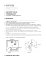
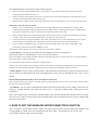
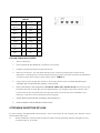
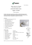
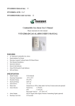
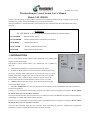
V-MUL-027-A (A0) Wireless Remote Control Switch User’s Manual Model: VST-RM588 Contain vital information on the product’s operation and installation. Read and retain carefully. If you are just installing this product, the manual MUST be given to the householder. The VST-RM588 is a wireless Remote Control Switch for use with mixed Fire & Carbon Monoxide Alarm Systems. WARNING: The VST-RM588 is for use with the following models of wireless alarm: VST-WS588IH Wireless Smoke Alarm VST-WS588IHR Wireless Smoke Alarm with Remote Test Feature VST-WH588I Wireless Heat Alarm VST-WC588IH Wireless Carbon Monoxide Alarm VST-WA588 Wireless Alarm Strobe Light 1. INTRODUCTION For use with wireless Smoke /Heat./Carbon Monoxide (CO) Alarms and wireless Alarm Strobe Light. The Remote Control Switch allows you, without the use of ladders or chairs, to: • Test the Smoke/Heat/CO Alarms and Alarm Strobe Light. • Locate the Smoke/Heat/CO Alarm and Alarms Strobe light sensing fire/CO by silencing all the other alarms (for 10 minutes). This is of great benefit, particularly at night as the source of the fire/CO can be quickly traced audibly. This is ideal for larger systems as people nearest the fire/CO can be quickly evacuated and/or control a fire if it is small. • Silence Nuisance Alarms: These can be silenced by pressing and releasing the Hush switch. • Fire & CO Indicators: In a Fire only System the Fire indicator on the VST-RM588 will flash to indicate a fire has been detected. If there is a fire, immediately evacuate the premises and telephone the fire brigade from outside. Do not silence the alarm unless you are sure there is no fire. In a mixed wireless Fire & CO System the Fire or CO indicator on the VST-RM588 will flash to indicate that Fire (smoke/heat) or Carbon Monoxide has been detected. If there is a fire, immediately evacuate the premises and telephone the fire brigade from outside. Do not silence the alarm unless you are sure there is no fire. If CO has been detected, open doors & windows while evacuating the premises. Telephone the appropriate authorities to report a Carbon Monoxide alarm has been activated. 2. SPECIFICATION ¾ ¾ ¾ ¾ ¾ ¾ ¾ ¾ ¾ Model No.: VST-RM588 Operation Temperature: -10°C—50°C Power Source: 2*1.5V AA Batteries Standby Current: 10uA max Current Consumption: 35mA max Working Frequency: 433/868MHZ Ambient Humidity: 10%-95% Low-voltage Indication: ≤2.1V Unit Dimension: 88.0mmX88.0mmX27.5mm 3. INSTALLATION 1 2 3 4 5 6 7 8 9 Position the Remote Control Switch 1.2 metres (approx) up on a wall in a suitable position on an exit route. Avoid locating near metal objects. Securely attach the mounting box of the unit to the wall using the fixing screws supplied. Find the 4-position dipswitch located on the back of Remote (see picture 1). Define the ID of your system by positioning the switches of the dipswitch in a random pattern. The ID will need to be the same for each alarm. This ID will differentiate your alarm system from similar systems nearby. See section 4 “HOW TO SET THE WIRELESS INTERCONNECTION FUNCTION ”. Using a pen or pencil, Slid the switches in each of the wireless devices to match the pattern you selected in step 4. Ensure that the sequence is not reversed Insert 2 AA batteries to compartment. NOTE POLARITY OF CONNECTIONS. (see picture 1) When the batteries have been fitted, The VST-RM588 green light indicator will flash in sequence to indicate power-up. Fix the Remote Control Switch assembly to the mounting box. Using the Test switch, verify that the Remote Control Switch activates all the alarms in the system. (If asome of the alarms have not been activated, then the ID coding procedure should be repeated. If there are still some problem, see the section 5 on “Troubleshooting RF LINK” ). Picture 1 3. USING REMOTE CONTROL Picture 2 VST-RM588 Remote Control Switch Functionality Indicators 1. When a wireless Smoke and Heat alarm is activated, the Fire light on the Remote Control will flash continually before alarm turning off. 2. When a wireless Carbon Monoxide alarm is activated, the Carbon Monoxide light on the Remote Control will flash continually before alarm turning off. 3. When batteries reach low level, three LED indicators on the unit will flash every 3 second in the same time. What to do when the Alarms sounds 1. If there is a fire, immediately evacuate the premises and telephone the fire brigade from outside. If the Carbon Monoxide light is flashing, open doors & windows while evacuating the premises. Telephone the appropriate authorities to report a Carbon Monoxide alarm has been activated. 2. When a Smoke/Heat alarm /Alarm strobe light sounds and the cause is not obvious, immediately press the ‘Locate’ switch. This will silence all the alarms except those sensing the fire. 3. Locate the alarm(s) sensing fire audibly. Be careful, check doors are not warm and that there is no sign of smoke before you open them (See escape plan in Smoke Alarm instructions for further details). 4. If you are fully satisfied that there is no fire but the Smoke/Heat alarm and Alarm strobe light is still continuing to alarm then press the ‘Silence’ switch. The Remote Control allows you to Locate, Silence or Test units as follows: • Locate button – primarily used to identify the Smoke/Heat/CO Alarm sensing fire/CO. When all the alarms are sounding due to a fire/CO (or nuisance alarm): Press and release Locate button. The RF indicator green light will come on continuously for 15 seconds indicate that an RF signal is being transmitted. This will silence all the alarms except those sensing fire/CO. This is a very useful feature. For example, consider twelve alarms sounding simultaneously, then the unit sensing the fire/CO can be identified audibly and the premises evacuated or the problem quickly resolved. • Silence Button -Used to silence nuisance alarms. This should only be pressed after the Locate button has been used to identify the Smoke/Heat/CO alarm that triggered the system, and it is determined that no fire or CO is present. Do not Silence the alarms unless you are sure there is no fire/CO. Press and release the silence button. The RF indicator green light will come on for 15 seconds to indicate that an RF signal is being transmitted. • Test Button– Use to test the Smoke/Heat/CO alarms and Alarm Strobe light or bases weekly. Switch the Test switch on. The RF indicator green light will come on for 15 seconds to indicate that an RF signal is being transmitted. Then:- the red light on the smoke alarm will flash rapidly (This indicates that the alarm has been tested in exactly the same way as if the test button of the alarm itself had been pressed. The alarm will also now be in Hush mode for the next 10 minutes). 4. HOW TO SET THE WIRELESS INTERCONNECTION FUNCTION The 1-4 numeric is for ID coding, total 16 coding. The switch usage is given in the table below (See TABLE1). ID 0 (coding 0000) is a public ID, it can communicate with other 15 IDs. Except ID0, the devices can only communicate with each other in same ID coding. TABLE1 1~4 ID 1~4 ID 0000 0 1000 8 0001 1 1001 9 0010 2 1010 10 0011 3 1011 11 0100 4 1100 12 0101 5 1101 13 0110 6 1110 14 0111 7 1111 15 FOLLOW THE ID SETUP STEPS 1. Remove the battery. 2. Press and hold the Test button for a minimum of 10 seconds. 3. Find the 4-position dipswitch located on the device. 4. Select one of the units. You will define the ID of your system by positioning the switches of the dipswitch in a random pattern. The ID will need to be the same for each alarm. This ID will differentiate your alarm system from similar systems nearby.(refer to TABLE 1) 5. Using a pen or pencil, change the switches in each of the wireless devices to match the pattern you selected in step 3. Ensure that the sequence is not reversed. 6. Insert 2 AA battery to the compartment. NOTE POLARITY OF CONNECTIONS. The unit only read the ID that has been set when they are first supplied power. Any changes to the switch after the unit is powered will not be recognized, and will require the power to be removed, Press and hold the Test button for a minimum of 10 seconds before powering again. 7. Fix the Remote Control Switch assembly to the mounting box. 8. Push test button to test the Remote Control Switch. 5.TROUBLE SHOOTING RF LINK If, when checking the RadioLINK interconnection, some of the alarms do not respond to the Remote Control Switch TEST button, then: (i) Ensure the Remote Control Switch has been activated correctly and the RF indicator red light has come on continuously for 10 seconds (ii) Repeat ID coding procedure (see section 4). (iii) Relocate the Remote Control Switch and/or rotate/relocate the RadioLINK units. There are a number of reasons why the RadioLINK signals may not reach all the alarms in your system (see section 6 on “Limitations of Radio Frequency Signals”). Try rotating the units or relocating the units (e.g. move them away from metal surfaces or wiring) as this can significantly improve signal reception. Rotating and/or relocating the units may move them out of the range of existing units even though they may have already been correctly set ID in the system. It is therefore important to check that all alarms are communicating in their final installed positions. If units are rotated and/or relocated, we recommend that all units are returned to the factory settings .Then reset ID Code all units again in their final positions. The RadioLINK interconnection should then be checked again. 6.LIMITATIONS OF RADIO COMMUNICATIONS Electronics radio communication systems are very reliable and are tested to high standards. However, due to their low transmitting power and limited range (required by regulatory bodies) there are some limitations to be considered: Radio transmitter equipment, such as the Remote Control Switch, should be tested regularly (at least weekly). This is to determine whether there are sources of interference preventing communication. The radio paths may be disrupted by moving furniture or renovations, and so regular testing protects against these and other faults. Receivers may be blocked by radio signals occurring on or near their operating frequencies, regardless of the house coding. The Remote Control Switch are designed to provide reasonable protection against harmful interference in residential installations. This equipment generates uses and can radiate radio frequency energy and, if not installed and used in accordance with the instructions, may cause interference to radio and television reception. However, there is no guarantee that interference will not occur in a particular installation. Interference from the Smoke Alarm system can be identified by temporarily turning the whole system off. Refer to the instructions supplied with the other products used for information on these. The user is encouraged to eliminate the interference by one or more of the following measures: ¾ ¾ Relocate the unit. Increase the distance between the Remote Control Switch and the device being affected. ¾ Consult the supplier or an experienced radio/television technician 7.END OF LIFE The Remote Control Switch is designed to last 10 years in normal use. However the unit must be replaced if: 1. 2. The unit is 10 years old under normal operation. If the Test switch fails to operate the alarms, or the RF indicator red light looks dim or fails to turn on, the battery in the unit may be depleted (excess use of the switch can shorten battery life). When the two red lights flashing rapidly, it is an indication that the battery level is low and the unit should be replaced. The Remote Control Switch must be switched off before disposing/recycling in accordance with the directive 2002/96/EC on waste electrical & electronic equipment (WEEE). 8.FIVE YEAR GUARANTEE(LIMITED) Vs-Top Electronics guarantees this product against any defects that are due to faulty material or workmanship for a five year period after the original date of consumer purchase. This guarantee only applies to normal conditions of use and service, and does not include damage resulting from accident, neglect, misuse unauthorized dismantling or contamination howsoever caused. Excessive use of the Remote Control Switch will shorten the battery life and is not covered. If this product has become defective it must be returned to Orientalert Electronics (see "Getting Your Remote Control Switch Serviced") with proof of purchase. If the product has become defective during the five year guarantee the manufacturer will repair/replace the unit without charge. This guarantee excludes incidental and consequential damages. Do not interfere with the product or attempt to tamper with it. This will invalidate the guarantee. The crossed out wheelie bin symbol that is on your product indicates that this product should not be disposed of via the normal household waste stream. Proper disposal will prevent possible harm to the environment or to human health. When disposing of this product please separate it from other waste streams to ensure that it can be recycled in an environmentally sound manner. For more details on collection and proper disposal, please contact your local government office or the retailer where you purchased this product. m other waste streams to ensure that it can be recycled in an environmentally sound manner. For more details on collection and proper disposal, please contact your local government office or the retailer where you purchased this product. Manufacturer: Xiamen Vs-Top Electronics Co., Ltd. 2nd floor, No. 107 Xiaguang Road, Xinyang Industrial District, Haicang, Xiamen, China. Tel: 0086-592-6017700 E-mail: [email protected] Fax: 0086-592-6017711 Website: www.orientalert.com