1
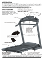
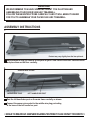
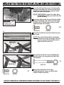
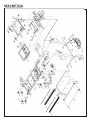
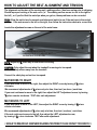
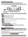
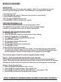
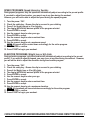
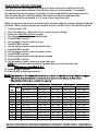
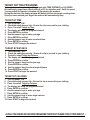
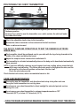
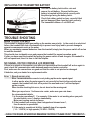
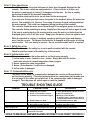
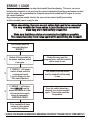
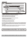
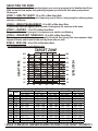
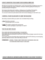
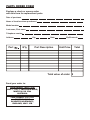
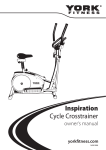
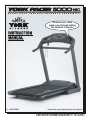
H E A R T
R A T E
C O N T R O L
F O L D A B L E
T R E A D M I L L
An electronic voice
guides you through setting
the treadmill computer
INSTRUCTION
MANUAL
11 / 2002 TWN
Product may vary slightly from the item pictured.
COMPLIES WITH EUROPEAN STANDARD EN957 PT 1+6 CLASS H C
YORK PACER 5000 HRC TREADMILL
SAFETY GUIDELINES:
Please read and follow the safety guidelines:
Before beginning any exercise program, you should consult with your doctor.
It is recommended that you undergo a complete physical examination.
Read this owner’s manual and follow the instructions.
Assemble and operate the YORK PACER 5000 HRC on a solid, level surface.
Keep the area behind the YORK PACER 5000 HRC clear.
Always allow a clear space measuring 1m wide and 2m long immediately behind
the YORK PACER 5000 HRC.
The treadmill will not operate without the safety key.
Never allow children on or near the treadmill.
The treadmill running mat will not stop immediately if any object becomes caught in the
mat or rollers - IN EMERGENCY: Pull the safety key cord to remove safety key.
Always check the treadmill before using it.
Make sure all parts are assembled, and nuts and bolts are tight.
Do not use the treadmill if the unit is disassembled in any way.
Keep hands away from moving parts.
The weight limit for this treadmill is 290 lbs (132 kgs).
Wear proper workout clothing: Do not wear loose clothing.
Do not wear shoes with leather soles or high heels. Tie all long hair back.
Don’t rock the unit from side to side.
Care should be taken when mounting and dismounting the unit.
Do not place any liquids on any part of the treadmill.
To prevent shock, keep all electric component, such as the motor, cable and switch away
from water.
Do not use any accessories that aren’t specifically recommended by the manufacturer,
these might cause injuries or cause the unit to fail.
Work within your recommended exercise level, do NOT work to exhaustion.
If you feel any pain or abnormal systems, STOP YOUR WORKOUT IMMEDIATELY.
Consult your physician immediately.
Turn off the treadmill while adjusting or working near the rear roller.
TAKE CARE TO PROTECT CARPETS AND FLOOR in case of leakages. This product is a
machine and contains moving parts which have been greased / lubricated and could leak.
WARNING - This appliance must be EARTHED.---IMPORTANT
The YORK PACER 5000 HRC is designed for the use and enjoyment of the serious trainer as well as
the dedicated user. By following the above precautions and using good judgement and common
sense, you will have safe and pleasurable exercise regimen with the YORK PACER 5000 HRC.
TOOLS REQUIRED - The tool enclosed in the carton is one allen key.
SHOULD YOU REQUIRE ANY ASSISTANCE REGARDING THIS PRODUCT PLEASE CONTACT YORK DIRECTLY.
HELP LINE
(8:30am- 4:30pm)
YORK BARBELL (U.K.) LTD.
YORK BARBELL (AUST.) LTD.
CHURCHILL WAY, DAVENTRY,
NORTHANTS, NN11 4YB ENGLAND
TEL: (01327) 701-824
FAX: (01327) 706-704
E-MAIL: [email protected]
UNIT 1, LOT 2, SWAFFHAM ROAD,
MINTO, N.S.W. 2566 AUSTRALIA
TEL: (02) 9603-8444
FAX: (02) 9603-8555
E-MAIL: [email protected]
HELP LINE
(8:30am- 4:30pm)
INTRODUCTION
The YORK PACER 5000 HRC TREADMILL has been designed and constructed to provide trouble
free usage and enjoyable exercise. You can greatly improve your understanding of the benefits of
exercising by carefully reading the instructions given in this manual.
Please familiarize yourself with the maintenance advice provided for you.
10 PROGRAMS - USER A, USER B,
SPEED INTERVAL, AEROBIC, WEIGHT LOSS,
HILL CLIMB, HR CONTROL, TARGET: TIME,
TARGET: DIST. & TARGET: CAL.
SPECIFICATIONS
POWER SUPPLY: 220~240V 50Hz
SPEED CONTROL : PUSH BUTTON
ELEVATION: POWER INCLINE 0%~10%
SPEED RANGE: 0 ~ 16 KPH
An electronic voice
guides you through setting
the treadmill computer
SAFETY KEY
HANDLE BAR WITH FOAM GRIP
COMPUTER SHOWS
ELEVATION, TIME,
CALORIE / PULSE,
DISTANCE, SPEED &
MAX. HEART RATE
HANDLE BAR POST
FOLD TREADMILL UP AND STAND
VERTICALLY FOR STORAGE
NON SLIP FOOTPAD
RUNNING MAT
BELT ADJUSTING BOLTS-ADJUST BELT TENSION &
TO CENTRALIZE MAT
MAIN FRAME
FOUR WHEELS TRANSPORTATION
SYSTEM ALLOWS YOU TO MOVE
THE TREADMILL EASILY WHEN FOLDED
* SHOULD YOU REQUIRE ANY ASSISTANCE REGARDING THIS PRODUCT PLEASE CONTACT YORK DIRECTLY. *
GENERAL
WE RECOMMEND YOU HAVE SOMEONE ASSIST YOU IN LIFTING AND
ASSEMBLING YOUR PACER 5000 HRC TREADMILL.
FOLLOW THESE INSTRUCTIONS CAREFULLY AND IT WILL MAKE IT EASIER
FOR YOU TO ASSEMBLE YOUR PACER 5000 HRC TREADMILL.
ASSEMBLY INSTRUCTIONS
1.
Product may vary slightly from the item pictured.
Ask someone to help you remove all the parts of your YORK PACER 5000 HRC from the carton
and place them on the floor carefully.
2.
SENSOR WIRE SOCKET
MIDDLE WIRE PLUG
LEFT HANDLE BAR POST
Rest the left handle bar post on the main frame carefully as shown.
Connect the sensor wire socket to the middle wire plug protruding
at the base of the left handle bar post.
* SHOULD YOU REQUIRE ANY ASSISTANCE REGARDING THIS PRODUCT PLEASE CONTACT YORK DIRECTLY. *
NOTE: DO NOT FULLY TIGHTEN THE BOLTS UNTIL YOU HAVE COMPLETED THE ASSEMBLY.
3.
Insert the left handle bar post into the handle
bar post mounting tube and secure the fixing
bracket onto the base frame, using six allen
head bolts and star washers.
LEFT
HANDLE BAR
POST
BASE FRAME
TAKE CARE
- DO NOT TRAP CABLE.
- DO NOT FULLY
TIGHTEN BOLTS YET.
FIXING BRACKET
NOTE: TAKE CARE to ensure the cable does
not get trapped when you attach the left
handle bar post.
Insert the right handle bar post into the handle
bar post mounting tube and secure the fixing
bracket onto the base frame, using six allen
head bolts and star washers.
X12
#5518-102
4.
#5518-91
Insert the handle bar into the handle bar post
as shown.
NOTE: One end of the handle bar protrudes
from the end of the foam grip, this end
must be inserted into the hole on the
right handle bar post first.
HANDLE BAR PROTRUDES
INSERT THIS
SIDE FIRST
RIGHT HANDLE
BAR POST
5.
LONG BOLT
Secure the handle bar to the left handle bar
post by using, one long allen head bolt and
star washer.
X1
SHORT BOLT
#5518-114
X1
#5518-102
#5518-91
Secure the handle bar to the right
handle bar post by using, one short allen
head bolt and star washer.
#5518-91
* SHOULD YOU REQUIRE ANY ASSISTANCE REGARDING THIS PRODUCT PLEASE CONTACT YORK DIRECTLY. *
6.
MIDDLE WIRE SOCKET
COMPUTER
WIRE PLUG
7.
HANDLE BAR POST
MOUNTING TUBE
Rest the computer console on the front handle
bar and connect the computer wire plug to the
middle wire socket protruding at the top of
the handle bar post.
Attach the computer console onto the handle
bar post mounting tubes as shown.
NOTE: TAKE CARE to ensure the cable does
not get trapped when you attach the
computer console.
If the console will not align and fit
easily, loosen all the bolts fitted so far and try again.
8.
Secure the computer console to the handle
bar post by using, four allen head bolts and
star washers.
X4
#5518-102
#5518-91
NOW tighten all the bolts you have fitted.
RECHECK
Recheck that all of the bolts are tightened securely for your safety and comfort.
Plug the power cable into a suitable AC outlet (220~240 Volt 50Hz).
Before you use the treadmill for the first time turn on the power switch and connect the
magnetic safety key.
Allow the treadmill to run for 10 minutes or so without anyone using it.
Check that the mat is tightened properly and runs smoothly.
* SHOULD YOU REQUIRE ANY ASSISTANCE REGARDING THIS PRODUCT PLEASE CONTACT YORK DIRECTLY. *
DESCRIPTION
PARTS LIST
KEY NO.
1
2
3
4
5
6
7
8
9
10
11
12
13
14
15
16
17
18
19
20
21
22
23
24
25
26
27
28
29
30
31
32
33
34
35
36
37
38
39
40
41
42
43
PART NO.
5518-01
5518-02
5518-03
5518-04
5518-05
5518-06
5518-07
5518-08
5518-09
5518-10
5518-11
5518-12
5518-13
5518-14
5518-15
5518-16
5518-17
5518-18
5518-19
5518-20
5518-21
5518-22
5518-23
5518-24
5518-25
5518-26
5518-27
5518-28
5518-29
5518-30
5518-31
5518-32
5518-33
5518-34
5518-35
5518-36
5518-37
5518-38
5518-39
5518-40
5518-41
5518-42
5518-43
Q'TY(PCS)
2
1
4
4
1
3
4
2
8
12
2
3
2
1
1
1
1
1
6
2
2
1
1
1
1
1
1
6
2
1
2
6
1
2
1
2
2
4
1
1
1
1
8
DESCRIPTION
CROSS BASE FRAME END CAP
CONTROLLER SIGNAL CABLE ( 1250mm )
PVC FOOT STOP
M6 X 25mm DOME HEAD SCREW
BASE FRAME
M8 X50mm ALLEN HEAD BOLT
MOVING WHEEL SLEEVE
BASE FRAME MOVING WHEEL
M8 X 1.6mm FLAT WASHER
M8 X 7.8mm NYLON HEX NUT
CROSS WHEEL END CAP
SNAP BUSHING
M5 X 40mm SOCKET HEAD SCREW
LOCK PIN CAP ( L )
LOCK PIN
LOCK PIN SPRING
RELEASE CABLE
LOCK PIN CAP ( R )
DECK CUSHION
REAR MOVING WHEEL SLEEVE
REAR MOVING WHEEL
SLEEVE
RELEASE LEVER
RELEASE HANDLE
M8 X 70mm ALLEN HEAD BOLT
RUBBER PAD
MAIN FRAME
M8 X 20mm SOCKET HEAD SCREW
LINKAGE SUPPORT SLEEVE
INCLINE SUPPORT LINK
INCLINE MOVING WHEEL
M8 X 30mm DOME HEAD SCREW
INCLINE WHEEL LINKAGE
E-RING
INCLINE LINKAGE SHAFT
TRACK SLIDER
BUSHING SPACER
CONNECTION TUBE BUSHING
MOVING SHAFT
INCLINE FRAME STRUCTURE
FIXED SHAFT
H FRAME
CONNECT BUSHING
44
45
46
47
48
49
50
51
52
53
54
55
56
57
58
59
60
61
5518-44
5518-45
5518-46
5518-47
5518-48
5518-49
5518-50
5518-51
5518-52
5518-53
5518-54
5518-55
5518-56
5518-57
5518-58
5518-59
5518-60
5518-61
16
2
2
2
2
1
1
1
1
1
1
2
6
1
1
2
1
1
M4 X 8mm DOME HEAD SCREW
GAS CYLINDER
M6 X 40mm SOCKET HEAD SCREW
TRACK STOPPER
HEX HEAD SPECIAL SCREW
INCLINE MOTOR NUT
INCLINE MOTOR
R PIN
INCLINE MOTOR PIN
ON / OFF POWER SWITCH
M8 X 20mm SOCKET HEAD SCREW
CONTROLLER SIGNAL CABLE ( 1250mm )
M5 X 10mm DOME HEAD SCREW
ON / OFF POWER BRACKET
AC INLET SOCKET
M4 X 6mm DOME HEAD SCREW
CIRCUIT BREAKER
CAPACI TOR
KEY NO.
62
63
64
65
66
67
68
69
70
71
72
73
74
75
76
77
78
79
80
81
82
83
84
85
86
87
88
89
PART NO.
5518-62
5518-63
5518-64
5518-65
5518-66
5518-67
5518-68
5518-69
5518-70
5518-71
5518-72
5518-73
5518-74
5518-75
5518-76
5518-77
5518-78
5518-79
5518-80
5518-81
5518-82
5518-83
5518-84
5518-85
5518-86
5518-87
5518-88
5518-89
Q'TY(PCS)
1
3
4
1
1
1
1
2
1
1
2
1
2
1
1
1
1
1
1
1
1
8
8
1
1
4
1
2
DESCRIPTION
M8 X 6.5mm HEX NUT
M8 X 40mm SOCKET HEAD SCREW
M8 X 20mm FRINGE HEAD SCREW
MOTOR BRACKET
OFF POWER SPRING
OFF POWER SLEEVE
OFF POWER BRACKET
M3 X 15mm PHILLIPS SCREW
MICRO SWITCH
INSULATION BRACKET
M4 X 8mm DOME HEAD SCREW
MICRO SWITCH BRACKET
M5 X 1.3mm SPRING WASHER
SPEED SENSOR W/ CABLE ( 580mm )
1.5 HP DC MOTOR
DRIVE BELT
RUNNING MAT
REAR ROLLER ASSEMBLY
M8 X 30mm SOCKET HEAD SCREW
CURVE WASHER
FRONT ROLLER ASSEMBLY
M6 X 35mm DOME HEAD SCREW
SIDE LANDING WASHER
RUNNING DECK
REAR DECK GUARD ( R )
M5 X 10mm DOME HEAD SCREW
REAR DECK GUARD ( L )
SIDE LANDING
90
91
92
93
94
95
96
97
98
99
100
101
102
103
104
5518-90
5518-91
5518-92
5518-93
5518-94
5518-95
5518-96
5518-97
5518-98
5518-99
5518-100
5518-101
5518-102
5518-103
5518-104
2
28
2
1
1
6
2
1
1
2
1
2
17
1
1
SINGLE-BACK SPONGE RUBBER
M8 X 0.8mm STAR WASHER
M8 X 65mm SOCKET HEAD SCREW
REAR END CAP TOP ( R )
REAR END CAP BOTTOM ( R )
M4 X 20mm DOME HEAD SCREW
M6 X 10mm DOME HEAD SCREW
REAR END CAP TOP ( L )
REAR END CAP BOTTOM ( L )
M6 X 1.5mm SPRING WASHER
MOTOR COVER
M5 X 16mm DOME HEAD SCREW
M8 X 15mm ALLEN HEAD BOLT
HANDLE BAR POST SUPPORT BRACKET ( R )
HANDLE BAR POST SUPPORT BRACKET ( L )
105
106
107
5518-105
5518-106
5518-107
1
2
2
COMPUTER CONSOLE
HANDLE BAR COVER ( L )
HANDLE BAR COVER ( R )
108
109
110
111
112
113
114
115
116
117
118
119
120
121
122
123
124
125
5518-108
5518-109
5518-110
5518-111
5518-112
5518-113
5518-114
5518-115
5518-116
5518-117
5518-118
5518-119
5518-120
5518-121
5518-122
5518-123
5518-124
5518-125
6
2
2
1
1
1
1
1
1
1
2
2
4
4
1
2
2
1
M3 X 10mm PHILLIPS HEAD SCREW
HANDLE BAR FOAM GRIP
HANDLE BAR END CAP
HANDLE BAR POST ( R )
FRONT HANDLE BAR
HANDLE BAR POST ( L )
M8 X 55mm ALLEN HEAD BOLT
SAFETY KEY
COMPUTER CONSOLE SIGNAL CABLE ( 550mm )
HANDLE BAR POST MIDDLE CABLE ( 1400mm )
M6 X 0.6mm STAR WASHER
M5 X 0.6mm STAR WASHER
M3 X 6mm PHILLIPS HEAD SCREW
M3 SPRING WASHER
FILTER
CU SCREW SLEEVE
M4 X 0.45mm STAR WASHER
CHOKE
OPERATING INSTRUCTIONS
The following procedure has been proven to be the safest and easiest method of mounting
the treadmill.
For your protection, carefully read and follow these simple steps:
1. Be sure the treadmill is positioned on a flat, level surface.
2. Make sure the magnetic safety key is not attached then plug in the treadmill power cable to a
suitable power socket and switch on at the socket.
3. Turn on treadmill power switch, which is located near where the power cable attaches to the
treadmill.
4. Straddle the running mat with your feet firmly planted on the right and left foot pads.
Stand close enough so you can extend your arms to touch all the buttons on the console.
CAUTION: Do not stand on the mat yet.
5. Insert the safety key.
6. Follow the instructions given by the computer.
( An electronic voice guides you though setting the treadmill computer. )
TIPS ON STEPPING ONTO THE TREADMILL
Once the treadmill is running at a low speed, place your weight on your right foot,
extend your left foot onto the running mat one normal step ahead of you.
Allow your left leg to follow the running mat movement.
Repeat this manoeuvre several times until you become familiar with the required pace.
Once you determine the pace, simply follow the “in motion” leg with the stationary leg in a normal
walking manner.
Continue to grip the handles firmly until you are walking normally.
After gaining stability and confidence, release your grip on the handles and let your arms swing
freely and naturally at your side.
NOTE: Walking straight on the treadmill is aided by focussing on a stationary object across
the room in front of you.
Walk as if you were approaching that object.
IN AN EMERGENCY
In a emergency take hold of the handrails and place your feet on the side rails provided,
once you are stable, pull out the safety key. The treadmill will then begin to decelerate
until it stops.
* SHOULD YOU REQUIRE ANY ASSISTANCE REGARDING THIS PRODUCT PLEASE CONTACT YORK DIRECTLY. *
HOW TO GET OFF THE TREADMILL
The following procedure has been proven to be the safest and easiest method of
dismounting the treadmill.
For your protection, carefully read and follow these simple steps.
1. Turn treadmill to low speed.
2. Firmly grip the handles to support yourself.
3. Remove your trailing foot from the running mat and place it on the foot pad on the
side of the treadmill.
This is very easy to do because the natural movement of walking will have shifted your
weight onto the foot that just stepped forward.
4. Shift your weight to the stationary foot on the foot pad, and remove the other foot from
the running mat and place it on the other foot pad.
You should now be in the starting position.
PAUSE
5. Press STOP STOP key to stop the treadmill and disconnect the safety key.
Unplug the treadmill from the main power outlet when finished.
IN AN EMERGENCY
In a emergency take hold of the handrails and place your feet on the foot pads provided,
once you are stable, pull out the safety key. The treadmill will then begin to decelerate
until it stops.
CARE AND MAINTENANCE
Use a warm damp cloth with mild detergent to keep your YORK PACER 5000 HRC
treadmill clean.
Do not clean between the mat and running board---The silicone lubricant is needed for
smooth movement of the mat.
Check parts for wear before use.
If in doubt do not use the treadmill and contact our helpline.
Pay particular attention to the fixing knobs and make sure they are tight.
Always replace the mat if worn and any other defective parts.
TAKE CARE TO PROTECT CARPETS AND FLOOR in case of leakages. This product is a
machine and contains moving parts which have been greased / lubricated and could leak.
SHOULD YOU REQUIRE ANY ASSISTANCE REGARDING THIS PRODUCT
PLEASE CONTACT YORK DIRECTLY.
HELP LINE
(8:30am- 4:30pm)
YORK BARBELL (U.K.) LTD.
YORK BARBELL (AUST.) LTD.
CHURCHILL WAY, DAVENTRY,
NORTHANTS, NN11 4YB ENGLAND
TEL: (01327) 701-824
FAX: (01327) 706-704
E-MAIL: [email protected]
UNIT 1, LOT 2, SWAFFHAM ROAD,
MINTO, N.S.W. 2566 AUSTRALIA
TEL: (02) 9603-8444
FAX: (02) 9603-8555
E-MAIL: [email protected]
HELP LINE
(8:30am- 4:30pm)
HOW TO ADJUST THE BELT ALIGNMENT AND TENSION
The alignment and tension of the running mat ( walking surface ) has been set up prior to shipping.
Should improper tracking of the mat occur ( ie. The walking surface moves too far to the right or
the left ), or if you find that the mat slips when you get on, these problems can be corrected.
TEST: Allow the mat to turn for several revolutions and watch to see if the mat runs in the central
position. If the mat moves to the left or the right, then follow the instructions below to correct this.
Locate the adjustment screws on the end of the main frame.
MAT ADJUSTMENT BOLTS
- USE ALLEN KEY TO ADJUST MAT
AS INSTRUCTED BELOW.
NOTE: Adjust by ½ a turn only to avoid over correcting.
CAUTION: Only adjust the mat when the treadmill is running at a low speed.
Keep others away from the treadmill.
Connect the safety key and set to a low speed.
MAT MOVES TO RIGHT
If your mat tends to move to the right, then adjust the RIGHT screw by turning it ½ a turn
clockwise.
We recommend adjustments of ½ a turn only at a time, then test ( as above ) each time.
If your mat continues to move to the right, then adjust the LEFT adjustment screw, by turning
½ a turn counter clockwise. TEST after each adjustment.
MAT MOVES TO LEFT
If your mat tends to move to the LEFT, then adjust the RIGHT screw by turning it ½ a turn
counter clockwise.
We recommend adjustments of ½ a turn only at a time, then test ( as above ) each time.
If the mat continues to move to the left, then adjust the LEFT adjustment screw,
by turning it ½ a turn clockwise. TEST after each adjustment.
* SHOULD YOU REQUIRE ANY ASSISTANCE REGARDING THIS PRODUCT PLEASE CONTACT YORK DIRECTLY. *
NOTE: For most people, one leg is stronger than the other, the running mat may tend to
move to that side because of the extra pressure exerted by the stronger leg.
If this occurs then either dismount the treadmill and allow the mat to track back to the middle,
or exert pressure to the side of the mat with the other leg, to track the mat back to the middle.
Or adjust the mat to compensate following the instructions for mat moves right or left.
MAT TOO LOOSE
If your mat appears to be loose, simply tighten both screws by an equal amount of ½ a turn
clockwise at a time, then test.
MAT TOO TIGHT
If it appears tight, simply loosen both screws by an equal amount of ½ a turn anti-clockwise at a
time, then test.
MAT STICKY (DOES NOT RUN SMOOTHLY)
You may feel after a period of time (depending on how often you use the machine)
that the mat feels sticky .
We recommend you apply a light covering of Silicone between the mat and the running board.
This procedure may be repeated as necessary.
WALKING MAT AND DECK LUBRICATION
This treadmill is equipped with a pre-lubricated, maintenance deck system. The mat/deck friction
may play a major role in the function and life of your treadmill, this requires periodic lubrication.
We recommend a periodic inspection of the deck. If the deck appears worn, please contact
our service department.
We recommend lubrication of the deck according to the following timetable:
Light use ( less than 3 hours per week ) every 8 months
Medium use ( 3-5 hours per week ) every 4 months
Heavy use ( more than 5 hours per week ) 2 months
HOW TO CHECK THE RUNNING MAT FOR PROPER LUBRICATION
- Disconnect the main power supply.
- Fold the treadmill up into the storage position.
- Feel the white back surface of the running mat.
If the surface is ( slick ) to the touch, then no further lubrication is required.
If the surface is dry to the touch, apply a suitable silicone lubricant.
We recommend that you use the following:
Lube-N-Walk Treadmill Lubrication Kit ( CODE: 5520 ) comes complete with instructions,
Available from your local Sports Retailer or contact YORK for your closest dealer.
* SHOULD YOU REQUIRE ANY ASSISTANCE REGARDING THIS PRODUCT PLEASE CONTACT YORK DIRECTLY. *
COMPUTER INSTRUCTIONS
Your computer is ideal for monitoring your performance and setting yourself targets.
You can monitor closely your improving condition and cardiovascular fitness.
H E A R T
R A T E
C O N T R O L
F O L D A B L E
T R E A D M I L L
SPEED
ELEVATION
UP
EMERGENCY STOP
SAFETY KEY
WARNING:
WEIGHT LOSS
PAUSE
COOL
DOWN
STOP
SLOW
HILL CLIMB
AEROBIC
User A
WHEN NOT IN USE REMOVE SAFETY KEY
AND STORE OUT OF REACH OF CHILDREN.
VIEW
START
DOWN
IN EMERGENCY - HOLD HANDRAIL
PULL THE CORD TO STOP
THE TREADMILL.
FAST
QUICK
START
SPEED INTERVAL
User B
Speed interval
ELEVATION
SAFETY when starting
Aerobic
Weight loss
SPEED
Hill climb
HR control
Target: Time
ENTER
Target: Dist.
Target: Cal.
CLEAR
ail
Hold the handr
treadmill.
or stopping the
KEYS
1.
2.
3.
Key: Adjust the elevation up and down.
QUICK
START
START
VIEW
4.
COOL
DOWN
5.
PAUSE
6.
7.
8.
STOP
Key: QUICK START- Manual workout.
START- To activate treadmill.
Key: Scans or displays time, distance, calories, pulse, or % of maximum heart rate.
Key: Interrupts the current workout and go directly into a four minute cool down routine.
Key: Slows the running belt to a complete stop.
Key: Adjusts the speed.
ELEVATION
SPEED
ENTER
CLEAR
Key: Primary function keys.
Key: Program keys: 2 custom programs,
Speed interval, Aerobic, Weight loss, Hill climb, HR control, Target: Time,
Target: Dist.,Target: Cal.
USING THE MAGNETIC SAFETY KEY
IMPORTANT: The treadmill will not work if the magnetic safety key is not in place.
Before starting the treadmill, attach the key to the computer, then attach the clip on the other end
to your clothing (above the waist). If this key is pulled out whilst you are running on the treadmill
then the mat will stop turning.
When the treadmill is not in use you should remove the safety key and store it somewhere
safe, away from the treadmill. This will prevent any unauthorised use of the treadmill.
Store the safety key in a safe place OUT OF REACH OF CHILDREN.
* SHOULD YOU REQUIRE ANY ASSISTANCE REGARDING THIS PRODUCT PLEASE CONTACT YORK DIRECTLY. *
WORKOUT PROGRAMS
QUICK START
The default settings are 0% elevation and a speed of 1 Km/H. You may adjust the speed or
elevation any time during the workout. The default time for this program is 30 minutes.
1. Turn the power “ON”.
2. Check the safety key and clip - Ensure the clip is secured to your clothing.
3. Press START for Quick Start.
4. Use the numeric keys to enter your age.
5. Press ENTER to confirm and begin your workout.
CUSTOM PROGRAM A & B
The first time you use this workout, you must program the routine.
The treadmill has 15 recordings to memorize elevation and speed settings.
In addition, the treadmill also records your age and workout time.
To program your personal exercise routine:
1. Turn the power “ON”.
2. Check the safety key - Ensure the clip is secured to your clothing.
3. Press 0 for Program A or 1 for Program B.
4. The display will show the program you have selected.
5. Press ENTER to confirm.
6. Use the numeric keys to enter your age.
7. Press ENTER to accept.
8. Use the numeric keys to enter a workout time.
9. Press ENTER to accept.
10. Press START to begin your workout.
11. The workout will start at 0% elevation and 1 Km/H. You may adjust the speed and elevation
throughout your workout. When your workout time is up, the treadmill will memorize all your
workout settings and repeat this routine when ever this program is selected again.
There are two ways to clear the custom program workout routine.
Option 1 - Clears old routine and sets new routine at the same time:
Just change the workout time, this will alert the computer to erase the previous programmed
routine. At this time, you may adjust your workout routine, at the end of the workout, the treadmill
will memorize the new routine and repeat this routine when ever this program is selected again.
Option 2 - Clears old routine only:
1. Select the program that you wish to clear ( A or B ).
2. Press CLEAR, the display will show “clear program? No”
3. Press CLEAR a second time and the display will show “ clear program ? Yes”
4. Press ENTER at this time and the memory will be cleared.
* SHOULD YOU REQUIRE ANY ASSISTANCE REGARDING THIS PRODUCT PLEASE CONTACT YORK DIRECTLY. *
SPEED PROGRAMS: Speed interval or Aerobic
During speed programs, only the speed will automatically adjust according to the pre-set profile.
If you wish to adjust the elevation, you may do so at any time during the workout.
However, you will not be able to adjust the speed during the speed program.
1. Turn the power “ON”.
2. Check the safety key - Ensure the clip is secured to your clothing.
3. Press 2 for Speed interval or 3 for Aerobic.
4. The display will show a workout profile of the program selected.
5. Press ENTER to accept.
6. Use the numeric keys to enter your age.
7. Press ENTER to accept.
8. Use the numeric keys to enter a workout time.
9. Press ENTER to accept.
10. Use the numeric keys to set a maximum speed.
NOTE: All speeds will be scaled down accordingly for the entire program.
11. Press ENTER to confirm.
12. Press START to begin your workout.
ELEVATION PROGRAMS: Weight loss or Hill climb
During elevation programs, only the elevation will automatically adjust according to the pre-set
profile. If you wish to adjust the speed, you may do so at any time during the workout. However,
you will not be able to adjust the elevation during the elevation program.
1. Turn the power “ON”.
2. Check the safety key - Ensure the clip is secured to your clothing.
3. Press 4 for Weight loss or 5 for Hill climb.
4. The display will show a workout profile of the program selected.
5. Press ENTER to accept.
6. Use the numeric keys to enter your age.
7. Press ENTER to accept.
8. Use the numeric keys to enter a workout time.
9. Press ENTER to accept.
10. Use the numeric keys to set a maximum elevation.
NOTE: All elevations will be scaled down accordingly for the entire program.
11. Press ENTER to confirm.
12. Press START to begin your workout.
* SHOULD YOU REQUIRE ANY ASSISTANCE REGARDING THIS PRODUCT PLEASE CONTACT YORK DIRECTLY. *
HEART RATE CONTROL PROGRAM
After you have set your program according to the steps below, the treadmill will activate
according to your warm up speed for the duration that you have requested. The treadmill
will automatically adjust by speed or elevation to achieve and maintain your target heart rate.
After the warm up time, it will take about 3-5 minutes to reach your target heart rate.
Your heart rate will be maintained at +/- 5 beats of your target heart rate.
When the monitor picks up your heart beat signal, the heart under the viewing display will light up
and blink. When you have reached your target heart rate, the HRC next to the heart will light up.
1. Turn the power “ON”.
2. Check the safety key - Ensure the clip is secured to your clothing.
3. Press 6 for Heart Rate Control program.
4. The display will show the program selected.
5. Press ENTER to accept.
6. Use the numeric keys to enter your age.
7. Press ENTER to accept.
8. Use the numeric keys to enter the workout time.
9. Press ENTER to accept.
10. Use the numeric keys to enter the warm up time.
11. Press ENTER to accept.
12. Use the numeric keys to enter the warm up speed.
13. Press ENTER to accept.
14. Use the numeric keys to enter your target heart rate.
NOTE: You can not input a value that is greater than your maximum heart rate.
( 220 less your age = Max. H. R. )
15. Press ENTER to confirm.
16. Press START to begin your workout.
NOTE: You must wear the transmitter chest strap in order to use the heart rate control program.
The chest strap will function at its best once you have worked up a little sweat.
The moisture will help to conduct the signals.
Max
HR
Age
155
160
165
170
175
180
185
190
195
200
205
65
60
55
50
45
40
35
30
25
20
<18
Percentage of Max Heart Rate (Beats per Minute)
Healthy Heart Weight Loss
Aerobic
Anaerobic
50 - 59%
60 - 69%
70 - 79%
80 - 89%
78 - 93
94 - 109
110 - 124
125 - 139
80 - 96
97 - 112
113 - 128
129 - 144
83 - 99
100 - 116
117 - 132
133 - 148
85 - 102
103 - 119
120 - 136
137 - 153
88 - 105
106 - 123
124 - 140
141 - 157
90 - 108
109 - 126
127 - 144
145 - 162
93 - 111
112 - 129
130 - 147
148 - 166
95 - 114
115 - 133
134 - 152
153 - 171
98 - 117
118 - 137
138 - 156
157 - 175
100 - 120
121 - 140
141 - 160
161 - 180
101 - 121
122 - 141
142 - 162
162 - 182
Maximum H/R
90 - 100%
140 - 155
145 - 160
149 - 165
154 - 170
158 - 175
163 - 180
167 - 185
172 - 190
175 - 195
181 - 200
183 - 205
* SHOULD YOU REQUIRE ANY ASSISTANCE REGARDING THIS PRODUCT PLEASE CONTACT YORK DIRECTLY. *
TARGET SETTING PROGRAMS
You may choose to workout by setting targets with TIME, DISTANCE or CALORIES.
All workouts by target have default settings of 0% for elevation and 1 Km/H for speed.
You may adjust the speed or elevation any time during the workout.
During the workout, the display window will default to show the target counting down.
Once you have reached your target, the workout will automatically stop.
TARGET BY TIME
1. Turn the power “ON”.
2. Check the safety key and clip - Ensure the clip is secured to your clothing.
3. Press 7 to select Target by Time.
4. The display will show the program selected.
5. Press ENTER to confirm.
6. Use the numeric keys to enter your age.
7. Press ENTER to confirm.
8. Use the numeric keys to enter a workout time.
9. Press ENTER to confirm.
10. Press START to begin the workout.
TARGET BY DISTANCE
1. Turn the power “ON”.
2. Check the safety key and clip - Ensure the clip is secured to your clothing.
3. Press 8 to select Target by Distance.
4. The display will show the program selected.
5. Press ENTER to confirm.
6. Use the numeric keys to enter your age.
7. Press ENTER to confirm.
8. Use the numeric keys to enter a target distance.
9. Press ENTER to confirm.
10. Press START to begin the workout.
TARGET BY CALORIES
1. Turn the power “ON”.
2. Check the safety key and clip - Ensure the clip is secured to your clothing.
3. Press 9 to select Target by Calories.
4. The display will show the program selected.
5. Press ENTER to confirm.
6. Use the numeric keys to enter your age.
7. Press ENTER to confirm.
8. Use the numeric keys to enter target calories.
9. Press ENTER to confirm.
10. Press START to begin the workout.
* SHOULD YOU REQUIRE ANY ASSISTANCE REGARDING THIS PRODUCT PLEASE CONTACT YORK DIRECTLY. *
POSITIONING THE CHEST TRANSMITTER
It is recommended that you wear the transmitter against your bare skin to ensure
flawless operation.
However if you wish to wear the transmitter over a shirt, moisten the shirt well under
the rubber electrodes.
Attach the adjustable elastic strap to the transmitter.
Moisten the rubber electrodes on the underside of the belt as shown.
Water or saliva can be used.
THE KEY TO FLAWLESS OPERATION IS TO WET THE RUBBER ELECTRODE
AREAS WELL.
The transmitter should be positioned next to your skin with the logo facing forwards in the
middle of the chest, just below the breast.
Adjust the strap to ensure a secure but comfortable fit.
The transmitter is activated automatically when on the body and is deactivated automatically
when removed.
NOTE: If you have difficulty obtaining a good regular heart rate reading, please check the belt,
which may need adjusting. The rubber electrodes must be flat against the skin, and the
belt must be in the correct position on the chest---Not too low!!
Check the electrodes are wet.
Check that the belt is clean, with no accumulated sweat or dirt.
CARE AND MAINTENANCE
Thoroughly wipe the transmitter, and allow the elastic strap to dry after each use.
Store your chest transmitter in a cool dry place.
Do not expose your chest transmitter to direct sunlight for extended periods such as
leaving it in a car.
o
Do not expose your chest transmitter to extreme temperatures above 122
o
o
o
Fahrenheit (50 C) or below 14 Fahrenheit (-10 C).
* SHOULD YOU REQUIRE ANY ASSISTANCE REGARDING THIS PRODUCT PLEASE CONTACT YORK DIRECTLY. *
REPLACING THE TRANSMITTER BATTERY
Unscrew the battery hatch with a coin and
remove the old battery. Ensure that the new
battery is inserted into the hatch correctly with
the plus sign facing the battery hatch.
Check that rubber gasket is clean, correctly fitted
and not damaged, then close the hatch securely.
The transmitter utilizes a 3 volt 2032 cell.
TROUBLE SHOOTING
WHEN TO CALL FOR HELP
This treadmill is designed with user safety as the number one priority. In the event of an electrical
failure, the treadmill will shut off automatically to prevent user injury and to prevent damage to
expensive components such as the motor.
When you encounter unusual behaviour from the treadmill, simply turn the power switch off and on
to reset the treadmill.
This should clear incidental errors and prepare the treadmill for normal operation again.
If, after you have reset the treadmill by turning the power switch off and on again, the treadmill is
still not operational, then it is time to call the helpline.
NO SIGNAL ON THE CONSOLE LCD WINDOWS
If there is no signal on the monitor, even after you have switched the treadmill off and on again to
reset, check the communication cable between monitor and motor controller.
First, make sure the connections are good and that the cable is not pinched or damaged.
If defective, ask your dealer for a replacement cable.
Error 1: Speed sensor error
Error 1 occurs when the console is not picking up the motor speed signal.
In other words, when the motor speed is not correctly fed back to the controller and
console, the treadmill will shut off to protect the user and error 1 will be displayed
on the console.
When trouble shooting this error, do not stand on the running mat.
When you report error 1 to the service center, make sure you note down
the circumstantial details.
1. Is the motor operational? For example, if the motor is not working when you push
the start button, error 1 displays immediately.
Motor and running mat do not move.
2. If the treadmill was running, then it stopped and showed error 1,
then the motor is operational.
3. If the motor is operational, did the treadmill stop at low speeds
( 1.0 - 1.5 KPH ) or high speeds ( 10 KPH - 12 KPH )
* SHOULD YOU REQUIRE ANY ASSISTANCE REGARDING THIS PRODUCT PLEASE CONTACT YORK DIRECTLY. *
Error 2: Over speed error
Error 2 occurs when the actual belt speed is faster than the speed displayed on the
console. This is also called run away protection. If the controller is broken, and
the motor is running out of control, it is dangerous to the user. So, this is a safety
mechanism to shut off the treadmill immediately.
When trouble shooting this error, do not stand on the running mat.
If you see error 2 when you first turn on the power to the treadmill, before the motor has
moved. One possibility for the error 2 occurring is because the mat had moved before
the motor moved. This could have happened during handling of the treadmill.
The controller thinks the motor moved even though it has not given power to the motor.
The controller thinks something is wrong. Simply turn the power off and on again to reset.
If the user is pushing hard on the running mat to cause the mat to run faster than the
displayed speed, error 2 will also occur. Simply turn the power off and on again to reset.
While the treadmill is running, it suddenly speeds up quickly and stops and displays
error 2 on the console. This means the controller is damaged and the motor is running
out of control. Call your dealer for service. Do not use the treadmill until it is repaired.
Error 3: Safety key error
Error 3 occurs when the safety key is not in positive contact with the console.
Check for positive contact of the safety key to the console.
Error 5: Incline motor error
This error occurs when the incline motor is not functioning properly.
1. Incline motor is over - loaded or over - heated. Simply wait until the incline
motor has returned to normal temperature, then try again.
2. Sensor connection cable has problem.
3. Sensor ( Potentiometer ) is defective or damaged.
4. Incline motor is damaged.
Error 11: Communication error
This error occurs when the communication between the console and the controller is
not functioning properly. Check the communication line connections first to make sure
it is not loose or the cables are not pinched. If the communication cable is damaged,
change it. Turn the power off and on again to reset the treadmill.
TROUBLE SHOOTING GUIDE
Problem
Treadmill will not start
Running belt slips
Running belt hesitates
when stepped on
Running belt is off center
Potential Cause
Corrections
1. Not plugged in
2. Safety key not inserted
3. House circuit breaker tri pped
4. Treadmill circuit breaker tripped
1. Plug into grounded outlet.
2. Insert the safety key into the co nsole.
3. Reset or replace fuse.
4.Reset the circuit breaker.
If happens again, lubricate the deck to
reduce friction betw een mat and deck.
5. Turn On/Off switch to "ON".
1. Adjust running mat tension.
2. Adjust drive belt tension .
1. Apply silicone lubricant.
2. Adjust running mat tension.
Center the running mat.
5. On/Off switch on "OFF"
1. Running mat not tight enough
2. Drive belt not tight enough
1. Insufficient lubrication
2. Running mat too tight / too loose
Running mat tension uneven
across the rear roller
* SHOULD YOU REQUIRE ANY ASSISTANCE REGARDING THIS PRODUCT PLEASE CONTACT YORK DIRECTLY. *
ERROR 1 CODE
This is a safety feature that can stop the treadmill from functioning. This error can occur
because the computer is not receiving the correct information from the speed sensor located
near the motor. As a precaution the computer stops the treadmill until it begins to receive
the correct feedback.
By performing a few simple checks, the error can be cleared quickly and easily,
and the treadmill can be ready for use.
When assembling, there are several cables that need to be connected.
It is very common for these cables to look like they are connected
when they are in fact not fully connected.
Make sure that these cables are connected as tightly as possible.
The connections may have come apart whilst assembling the treadmill.
The treadmill does not
move and displays
“ERROR 1”
1.
Switch off the treadmill at
the mains, and then switch
it on again.
Doing this may reset the
program error, and the treadmill
will be ready to use.
2.
If “ERROR 1” still shows
switch off and push the
running mat round
(1 cycle) using your feet.
Then switch back on.
This should reset the sensor,
and the treadmill will be ready
to use.
3.
If “ERROR 1” still shows,
then UNPLUG from the
mains and check all of the
wire connections made
during the assembly.
(SEE BOLD PRINT)
Once the cables have been
checked, turn on the treadmill
again. This should eradicate
the problem.
If the treadmill still does
not move, then please
contact the helpline.
* SHOULD YOU REQUIRE ANY ASSISTANCE REGARDING THIS PRODUCT PLEASE CONTACT YORK DIRECTLY. *
EXERCISE GUIDE
FITNESS
Many things contribute to fitness and well being but the most important factor is the condition of
your heart and lungs and how efficient they are in delivering oxygen via your blood to your muscles.
Your muscles use this oxygen to provide enough energy for daily activity.
This is called aerobic activity (with oxygen).
When you are fit your heart and lungs work well and efficiently.
This means your heart will not have to work so hard. It will pump a lot fewer times per minute so
reducing the wear and tear on your heart.
This in turn reduces the chances of your suffering heart disease.
Fitness also helps you control your weight and reduces the effects of aging and stress.
You come across the need for fitness continually in everyday life.
When you are fit you can walk briskly up hills and stairs without being too out of breath once at the
top you recover quickly.
As you can see there are great advantages in being fit.
HOW TO IMPROVE YOUR FITNESS
Like any muscle in your body your heart can be strengthened by systematic physical exercise which
requires an increased blood flow and heart rate.
You can measure your heart rate by taking a pulse reading.
Your heart of pulse rate corresponds directly to your exertion level and exercise efficiency.
To improve your fitness in a safe and effective way you need to exercise at a high enough level to
improve your aerobic fitness.
The area between these 2 levels is called the target zone.
It is important to exercise at the right intensity to stay within this zone.
For the best results you should exercise within the target zone and gradually increase the duration.
Ideally you should aim to exercise (within zone) for at least 15-20 minutes continuously,
3-4 times per week.
CAUTION
DO NOT TRY TO DO TOO MUCH TO QUICKLY START GRADUALLY AND BUILD UP.
IF YOU BECOME ILL, IF YOU ARE UNDER DOCTOR CARE, OR OVER 35-40 AND NOT CURRENTLY
TAKING REGULAR EXERCISE THEN WE WOULD ADVISE YOU NOT TO START TO EXERCISE
WITHOUT CONSULTING YOUR DOCTOR.
* SHOULD YOU REQUIRE ANY ASSISTANCE REGARDING THIS PRODUCT PLEASE CONTACT YORK DIRECTLY. *
TARGET ZONE
PULSE
RATE
MAXIMUM PULSE RATE
85% OF MAX.
EXERCISE SO THAT YOUR PULSE STAYS IN
THIS RATE FOR AT LEAST 15-20 MINUTES
70% OF MAX.
55% OF MAX.
COOL DOWN LEVEL
RESET PULSE
TIME
WARM UP
COOL DOWN
THIS IS HOW YOUR PULSE SHOULD BEHAVE DURING GENERAL FITNESS EXERCISE.
REMEMBER TO WARM UP AND COOL DOWN FOR A FEW MINUTES.
HEART ZONE SELECTION GUIDELINES
In order to set your personal target heart zone, you will need to:
- Calculate your maximum heart rate.
- Select a zone based on your current fitness level.
Calculating your maximum heart rate
The standard method for calculating heart rate training zone is based on estimating maximum
heart rate using the formula 220 minus the persons age in years. Some practitioners believe
that a woman estimated maximum heart rate can be calculated more accurately by using 226
instead of 220.
The important issue with all estimating calculations is that in reality they can vary by plus or
minus 15 bpm and at best are only an indication of actual results.
Estimated Maximum Heart Rate = 220 - Age (Year)
* SHOULD YOU REQUIRE ANY ASSISTANCE REGARDING THIS PRODUCT PLEASE CONTACT YORK DIRECTLY. *
SELECTING THE ZONE
If you have not exercised for some time begin your exercise program in the Healthy Heart Zone.
Start for the first few weeks, and gradually progress up to the zone that meets you personal
fitness goal.
ZONE 1.- HEALTHY HEART - 50 to 59% of Max Heart Rate.
If you are a beginner with the goal of improving overall fitness, losing weight or reducing stress,
exercise in this zone.
ZONE 2.- WEIGHT MANAGEMENT - 60 to 69% of Max Heart Rate.
If you already exercise regularly with the aim of losing body fat, exercise in this zone.
ZONE 3.- AEROBIC - 70 to 79% of Max Heart Rate.
Progress to this zone if your goal is to improve your aerobic conditioning.
ZONE 4.- ANAEROBIC THRESHOLD - 80 to 89% of Max Heart Rate.
This is the zone in which to improve anaerobic threshold. Exercising I this zone requires a high
degree of fitness, and should not be used by those who are unfit.
ZONE 5.- RED LINE - 90 to 100% of Max Heart Rate.
For professional supervised athletes only.
TARGET ZONE
200
RED
-LINE
ANAE
ROBI
C THR
90-10
ESHO
0% M
AERO
L
D
HR
BIC ZO
ZONE
NE
80-90
% MH
R
WEIGH
T MAN
7
0
8
AGEM
0% M H
ENT Z
R
ONE
HEALTHY
6
0-70%
HEART Z
MHR
ONE
50-60% M
HR
160
140
120
100
80
60
Max
Age
HR
155
65
160
60
165
55
170
50
175
45
180
40
185
35
190
30
195
25
200
20
205 <18
180
ZON
E
Maximum Heart Rate (MHR) = 220 - AGE
20
30
40
50
60
70 AGE
160
140
120
100
HEART RATE
HEART RATE
180
200
80
60
Percentage of Max Heart Rate (Beats per Minute)
Healthy Heart Weight Loss
Aerobic
Anaerobic
50 - 59%
60 - 69%
70 - 79%
80 - 89%
78 - 93
94 - 109
110 - 124
125 - 139
80 - 96
97 - 112
113 - 128
129 - 144
83 - 99
100 - 116
117 - 132
133 - 148
85 - 102
103 - 119
120 - 136
137 - 153
88 - 105
106 - 123
124 - 140
141 - 157
90 - 108
109 - 126
127 - 144
145 - 162
93 - 111
112 - 129
130 - 147
148 - 166
95 - 114
115 - 133
134 - 152
153 - 171
98 - 117
118 - 137
138 - 156
157 - 175
100 - 120
121 - 140
141 - 160
161 - 180
101 - 121
122 - 141
142 - 162
162 - 182
Red line
90 - 100%
140 - 155
145 - 160
149 - 165
154 - 170
158 - 175
163 - 180
167 - 185
172 - 190
175 - 195
181 - 200
183 - 205
* SHOULD YOU REQUIRE ANY ASSISTANCE REGARDING THIS PRODUCT PLEASE CONTACT YORK DIRECTLY. *
HOW TO MONITOR YOUR HEART RATE DURING EXERCISE
Now that you know where your training zone is, you’ll I have to monitor yourself to be sure you’re
in it. Here’s a simple rule, if you can’t hold a conversation without gasping for breath you’re
probably above your training zone.
To know precisely where you’re working - making sure you’re getting all the benefits We recommend you check your heart rate periodically throughout your workout.
You can use the electronic pulse monitor which will count and display your heart rate for you.
CONTROL YOUR PULSE RATE TO KEEP WITHIN ZONE
How hard you exercise affects your pulse rate, it is determined by two thing:
1. Rate: How fast you exercise.
e.g. Speed you cycle, run or step.
2. Load: The resistance against which you exercise.
e.g. Tension you apply on cycle, step or run up hill.
THE PULSE RATE RULES
If your pulse rate is too low exercise faster or increase load.
If your pulse rate is too high exercise slower or decrease load.
If your pulse rate goes up towards the end of your exercise, you are trying to exercise for too long,
shorten the time.
If your pulse rate does not quickly return to normal after exercise (5-10 minutes) you are not giving
your body chance to recover, reduce how often you exercise.
REMEMBER - GENERAL FITNESS IS BEST IMPROVED BY INCREASING HOW LONG
YOU EXERCISE RATHER THAN BY HOW HARD.
* SHOULD YOU REQUIRE ANY ASSISTANCE REGARDING THIS PRODUCT PLEASE CONTACT YORK DIRECTLY. *
HOW LONG TO EXERCISE?
To qualify as a true aerobic exercise with all the benefits we're mentioned, you must maintain your
heart rate within your training zone for at least 12 uninterrupted minutes.
If you exercise longer than 60 minutes the benefits are reduced and the risk of injury is increased.
If you're just starting out on a new exercise program we're commend you stay at the 12 minute
minimum for at least a week. When you feel you're ready to go longer, increase your time no more
than 10% a week. Don't push yourself too hard.
You should never feel exhausted during or following exercise.
TEST YOUR FITNESS LEVEL AND CHECK YOUR PROGRESS
You can use your computer to control your exercise intensity and to monitor your progress.
The time it takes for your pulse to return to normal, after exercise, is an indicator of
your fitness level.
During the first minute of your cool-down phase you will experience a drop in your pulse rate.
The bigger the drop in that minute -- the fitter you are.
TO CHECK YOUR PROGRESS:
1. Monitor your pulse rate the moment you end the aerobic phase of your workout and note your
pulse rate.
2. Begin slowing down for the cool down phase.
3. After 60 seconds note the rate again.
The bigger the drop in that minute-the fitter you are.
To check your progress repeat this test every few weeks using the same duration and exercise
intensity each time.
Keep a record of the results to help you monitor your progress.
* SHOULD YOU REQUIRE ANY ASSISTANCE REGARDING THIS PRODUCT PLEASE CONTACT YORK DIRECTLY. *
LIMITED WARRANTY
WARRANTY
YORK BARBELL LTD. warrants this product to be free from defects in workmanship and material,
under normal use and conditions, for a period of one year on all steel parts, thirty days on all vinyl
and upholstery, and ninety days on all other parts.
This warranty extends to the original purchaser only.
It is recommended that the original receipt be kept with the manual.
YORK BARBELL LTD. will provide a replacement part free of charge when a defect is found during
the warranty period. If a repair is necessary, please contact our Customer Service Department.
Under no circumstances will YORK BARBELL LTD. be responsible for damages or failures that
occur as a result of improper assembly, or failure to operate the product correctly.
This warranty does not cover misuse, abuse, freight damage and/or alterations or repairs not
made by YORK BARBELL LTD. or a recommended service center.
In the event a return is necessary, call our Customer Service Department for further instructions.
Under no circumstances will returns be allowed without the Return Authorization by our
Customer Service Department.
Returns must be sent pre-paid, with the original packaging or equivalent.
This warranty does not apply when the product is used for rental or commercial use.
This warranty gives you specific legal rights, and you may also have other rights which
vary from state to state.
REPLACEMENT PARTS
ORDERING
To order replacement parts, simply call our Customer Service Department.
Monday through Friday, 8:30am until 4:30pm (excluding holidays).
To help us assist you, please have the following information ready:
1) Model: PACER 5000HRC W/ VOICE.
2) Serial Number: Located on the front of the main frame.
3) The part description and order number.
REGISTRATION
CONSUMER RESPONSIBILITY
In order to activate your warranty, you must mail in the supplied registration form found on the following page.
Failure to send in the registration form will void your warranty.
Fill in the form and send it to:
CUSTOMER SERVICE DEPARTMENT:
HELP LINE
(8:30am- 4:30pm)
YORK BARBELL (U.K.) LTD.
YORK BARBELL (AUST.) LTD.
CHURCHILL WAY, DAVENTRY,
NORTHANTS, NN11 4YB ENGLAND
TEL: (01327) 701-824
FAX: (01327) 706-704
E-MAIL: [email protected]
UNIT 1, LOT 2, SWAFFHAM ROAD,
MINTO, N.S.W. 2566 AUSTRALIA
TEL: (02) 9603-8444
FAX: (02) 9603-8555
E-MAIL: [email protected]
HELP LINE
(8:30am- 4:30pm)
PARTS ORDER FORM
Enclose a check or money order
with this form for replacement parts.
Date of purchase
Name of location where purchased
Model number
Last name, First name
Telephone number
Address
Part
City
Q'ty
State
Part Description
Zip/Postcode
Unit Price
Total value of order $
Send your order to:
YORK BARBELL (AUST.) LTD.
UNIT 1, LOT 2, SWAFFHAM ROAD,
MINTO N.S.W. 2566
AUSTRALIA
YORK BARBELL (U.K.) LTD.
CHURCHILL WAY,
DAVENTRY, NORTHANTS,
ENGLAND, NN11 4YB
Total