1
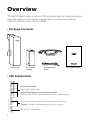
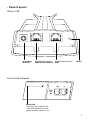
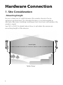
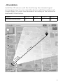
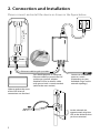
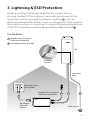
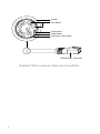
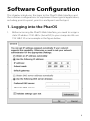
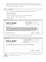
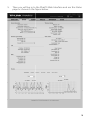
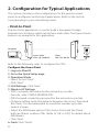
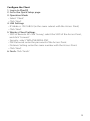
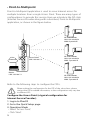
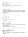
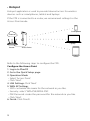
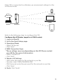
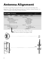
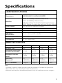
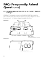
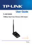
Installation Guide
Outdoor CPE
CPE210 / CPE220 / CPE510 / CPE520
CONTENTS
Overview
1
Hardware Connection
Site Consideration
Connection and Installation
Lightning & ESD Protection
3
5
6
Software Configuration
Logging into the PharOS
Configuration for Typical Applications
• Point-to-Point
• Point-to-Multipoint
• Hotspot
8
11
11
13
15
Antenna Alignment
17
Specifications
18
FAQ (Frequently Asked Questions)
19
Overview
TP-LINK's Pharos series outdoor CPEs are dedicated to outdoor wireless
network solutions. This guide is applicable to products including
CPE210, CPE220, CPE510 and CPE520.
• Package Contents
Power Cord
Pharos CPE
Passive PoE
Adapter
Pole Mounting
Straps
Installation Guide
• LED Explanation
AP/AP Router mode:
All four LEDS remain solid.
Client/Bridge/Repeater/AP Client Router mode:
That the more LEDs lit will indicate better wireless signal strength.
LAN1 LAN0 POWER
1
On: A device is connected to this port, but there is no activity.
Flashing: A device is connected to this port, and is active.
On: The CPE is powered on.
• Panel Layout
Pharos CPE:
Grounding
Terminal
Shielded Ethernet Port
LAN0 (Passive PoE in)
Shielded Ethernet Port
LAN1
RESET
Passive PoE Adapter:
Power LED
The Power LED indicates the
status of the electric current:
green (0~0.8A), red (0.8A~1A).
2
Hardware Connection
1. Site Consideration
• Mounting Height
Ensure a clear line of sight between the wireless devices for an
optimum performance. An elevated location is recommended as
obstacles like trees, buildings and large steel structures will weaken the
wireless signal.
See 'Q2' in 'FAQ' for details about how to calculate the minimum
mounting height of the devices.
Line of Sight
Side View
3
• Orientation
Install the CPE devices with the front facing the intended signal
receiving devices. You can orient the devices with the assistance of
Google Maps, GPS and some landmarks according to the horizontal
beamwidth listed below.
Models
CPE210
CPE220
CPE510
CPE520
Horizontal Beamwidth
70°
45°
45°
50°
shenzhen
H
Be oriz
am on
w tal
id
th
Lin
e
of
Si
gh
t
A
B
4
2. Connection and Installation
5734 MADE IN CHINA
5GHz 300Mbps 13dBi Outdoor CPE
Power: 24V
1A
Model: CPE510
Default Settings:
IP: 192.168.0.254
Username: admin
Password: admin
This device complies with part 15 of the FCC Rules. Operation is
subject to the following two conditions:(1) This device may not cause
harmful interference,and (2) this device must accept any interference
received, including interference that may cause undesired operation.
IC:8853A-CPE510
FCC ID:TE7CPE510
Please connect and install the device as shown in the figure below.
LAN0
POE
LAN
Ethernet cable length up to 60m
You should prepare an adequate
Ethernet cable to connect the CPE
and the passive PoE adapter.
Shielded CAT5e (or above) cable
with ground wire is recommended
(refer to the next section).
Connect to a computer,
router or switch.
(Depending on your
intended usage and/or
network topology.)
Slide to replace the cover
of the CPE when all
connections are finished.
At the selected site,
approximately align the
CPE to the direction that
you have oriented.
5
3. Lightning & ESD Protection
Proper grounding is extremely important for outdoor devices.
By using shielded CAT5e (or above) cable with ground wire for the
connection and the provided PoE adapter (method 1 ), you can
effectively eliminate ESD attacks. If you use the general CAT5e cable for
the connection, then it is necessary to connect the grounding terminal
of the CPE to earth ground through grounding cable (method 2 ).
Two Methods:
1 Shielded CAT5e (or above)
Cable with Ground Wire
2 Grounding Terminal and Cable
CPE
Grounding
Terminal
Grounding
Cable
Grounded 3-wire
Power Outlet
Shielded CAT5e (or above)
Cable with Ground Wire
1
PoE Adapter
with Earth
Ground
1
1
2
Earth Ground
6
Sheath
Twisted Pair
Ground Wire
Cable Shield
Secondary Cable Shield
Shielded RJ45 Connector
Shielded CAT5e (or above) Cable with Ground Wire
7
Software Configuration
This chapter introduces the login to the PharOS Web Interface and
the software configurations to implement three typical applications,
including point-to-point, point-to-multipoint and hotspot.
1. Logging into the PharOS
1.
Before accessing the PharOS Web Interface, you need to assign a
static IP address 192.168.0.x (2≤x≤253) to your computer. We use
192.168.0.10 as an example in the figure below.
8
2.
Open your web browser, type 'http://192.168.0.254' in the address
field and press 'Enter'. It is recommended to use the latest version of
Google Chrome, Safari or Firefox.
3.
The 'Login' page will appear, set the parameters as below.
• Username: admin.
• Password: admin.
• Region: select according to your country/region.
• Select 'I agree to these terms of use'.
• Click 'Login'.
4.
At the first login, change the 'Password' for safety.
For subsequent logins, you only need to enter the username and password
that you have set to log in.
9
5.
Then you will log in to the PharOS Web Interface and see the Status
page as shown in the figure below.
10
2. Configuration for Typical Applications
This section introduces the configurations for the point-to-point,
point-to-multipoint and hotspot applications. Refer to the section
corresponding to your networking needs.
• Point-to-Point
Point-to-Point application is used to build a transparent bridge
between two locations which are far from each other. The figure shown
below is an example for this application.
IP camera
Computer
Access Point
LAN: 192.168.0.254
Client
LAN: 192.168.0.2
Refer to the following steps to configure the CPEs.
Configure the Access Point
1. Log in to PharOS
2. Go to the Quick Setup page
3. Operation Mode
• Select 'Access Point'.
• Click 'Next'.
4. LAN Settings: Click 'Next'.
5. Wireless AP Settings
• SSID: customize the name for the network as you like.
• Security: select 'WPA-PSK/WPA2-PSK'.
• PSK Password: create the password for the network as you like.
• Distance Setting: enter the distance between the Access Point and
the Client. It is recommended to round the number up to the
nearest integer.
• Select the MAXtream option if the Access Point and the Client
both are Pharos outdoor CPEs. (Refer to 'Q4' in 'FAQ' for details about
MAXtream)
• Click 'Next'.
6. Finsh: Click 'Finish'.
11
Configure the Client
1. Log in to PharOS
2. Go to the Quick Setup page
3. Operation Mode
• Select 'Client'.
• Click 'Next'.
4. LAN Settings
• IP Address: 192.168.0.2 (in the same subnet with the Access Point)
• Click 'Next'.
5. Wireless Client Settings
• SSID of Remote AP: click 'Survey', select the SSID of the Access Point,
and click 'Connect'.
• Security: select 'WPA-PSK/WPA2-PSK'.
• PSK Password: enter the password of the Access Point.
• Distance Setting: enter the same number with the Access Point.
• Click 'Next'.
6. Finsh: Click 'Finish'.
12
• Point-to-Multipoint
Point-to-Multipoint application is used to serve Internet access for
multiple locations from a single Access Point. There are many types of
configurations to provide this service. Here we introduce the ISP-style
(Internet Service Provider along with subscribers) Point-to-Multipoint
application, as shown in the figure below.
AP Client Router
LAN: 192.168.0.254
WAN: Dynamic IP
Access Point
LAN: 192.168.7.2
Internet
Router
LAN: 192.168.7.1
AP Client Router
LAN: 192.168.0.254
WAN: Dynamic IP
AP Client Router
LAN: 192.168.0.254
WAN: Dynamic IP
Refer to the following steps to configure the CPEs.
When making the configuration for the CPE of the subscribers, please
contact the ISP for related information, as the configuration may vary due
to different ISPs.
Configure the Access Point (a typical configuration for
Internet Service Provider):
1. Log in to PharOS
2. Go to the Quick Setup page
3. Operation Mode
• Select 'Access Point'.
• Click 'Next'.
13
4. LAN Settings
• IP Address: 192.168.7.2 (in the same subnet with the router).
• Click 'Next'.
5. Wireless AP Settings
• SSID: customize the name for the network as you like.
• Security: select 'WPA-PSK/WPA2-PSK'.
• PSK Password: create the password for the network as you like.
• Distance Setting: enter the distance between the Access Point and
the most remote client. It is recommended to round the number up
to the nearest integer.
• Select the MAXtream option if the Access Point and the AP Client
Routers all are Pharos outdoor CPEs. (Refer to 'Q4' in 'FAQ' for details
about MAXtream)
• Click 'Next'.
6. Finsh: Click 'Finish'.
Configure the AP Client Router (a typical configuration for
subscribers)
1. Log in to PharOS
2. Go to the Quick Setup page
3. Operation Mode
• Select 'AP Client Router(WISP Client)'.
• Click 'Next'.
4. WAN Connection Type
• Select 'Dynamic IP'.
• Click 'Next'.
5. Wireless Client Settings
• SSID of Remote AP: click 'Survey', select the SSID of the Access Point,
and click 'Connect'.
• Security: select 'WPA-PSK/WPA2-PSK'.
• PSK Password: enter the password of the Access Point.
• Distance Setting: enter the distance between the client and the
remote Access Point to be connected. It is recommended to round
the number up to the nearest integer.
6. Wireless AP Settings: Click 'Next'.
7. Finsh: Click 'Finish'.
After finishing the CPE configuration for the subscribers, please change the
IP settings of your computer to 'Obtain an IP address automatically' and
'Obtain DNS server address automatically'.
14
• Hotspot
Hotspot application is used to provide Internet access for wireless
devices such as smartphones, tablets and laptops.
If the CPE is connected to a router, we recommend setting it in the
Access Point mode.
Smartphone
Internet
Laptop
Router
Access Point
Tablet
Refer to the following steps to configure the CPE.
Configure the Access Point
1. Log in to PharOS
2. Go to the Quick Setup page
3. Operation Mode
• Select 'Access Point'.
• Click 'Next'.
4. LAN Settings: Click 'Next'.
5. WAN AP Settings
• SSID: customize the name for the network as you like.
• Security: select 'WPA-PSK/WPA2-PSK'.
• PSK Password: create the password for the network as you like.
• Click 'Next'.
6. Finish: Click 'Finish'.
15
If the CPE is connected to a Modem, we recommend setting it in the
AP Router mode.
Smartphone
Internet
Laptop
Modem
AP Router
Tablet
Refer to the following steps to configure the CPE.
Configure the AP Router (equal to a SOHO router)
1. Log in to PharOS
2. Go to the Quick Setup page
3. Operation Mode
• Select 'AP Router'.
• Click 'Next'.
4. WAN Connection Type
*These settings may vary depending on the ISP. Please contact
your ISP for the correct information.
• Select 'Dynamic IP'.
• Click 'Next'.
5. Wireless AP Settings
• SSID: enter the name for the network as you like.
• Security: select 'WPA-PSK/WPA2-PSK'.
• PSK Password: enter the password for the network as you like.
• Click 'Next'.
6. Finsh: Click 'Finish'.
16
Antenna Alignment
In order to get the best performance, you can precisely align the
direction of the CPE with the assistance of 'Wireless Signal Quality' on
'STATUS' page of the PharOS Web Interface.
Adjust the direction of the CPE until
the device reaches the highest SNR.
WISP
WISP
17
Specifications
HARDWARE FEATURES
Power Supply
CPE520/CPE220: 275.83*79*60.3mm
CPE510/CPE210: 224.34*79*60.3mm
LAN0: 10/100Mbps Ethernet Port(PoE IN)
LAN1: 10/100Mbps Ethernet Port
GND: Grounding Terminal for Lightning Protection
RESET: Button to restore the device to Factory Default
24V Passive PoE Adapter Included
ESD Protection1
15kV
Lightning Protection1
Up to 6kV
Operating
Temperature
-30℃ ~ 70℃ (-22℉~158℉)
Operating Humidity
10% ~ 90%
Certification
CE, FCC, RoHS, IPX5
Dimensions
Interface
WIRELESS FEATURES
Models
CPE210
CPE220
CPE510
CPE520
Antenna Gain
9dBi
12dBi
13dBi
16dBi
Horizontal Beamwidth/
Elevation Beamwidth2
70°/ 45°
45°/ 30°
45°/ 30°
50°/ 20°
Maximum Transmit
Power3
27dBm
30dBm
27dBm
30dBm
Operating
Frequency3
2.42.4835GHz
2.42.4835GHz
5.155.85GHz
5.155.85GHz
802.11 Standards
11b/g/n
11b/g/n
11a/n
11a/n
Note:
1. Estimation is based on copper grounding cable and shielded CAT5e cable with ground wire.
2. Beamwidth values may vary throughout operating frequency.
3. Maximum transmit power and operating frequency may vary in different countries or regions.
18
FAQ (Frequently Asked
Questions)
Q1. How to restore the CPE to its factory default
settings?
With the CPE powered on, press and hold the 'RESET' button of the
CPE or the 'Remote Reset' button of the passive PoE adapter for about
8 seconds until the Wireless Signal Strength LEDs flash.
Method 1:
RESET Button
Press & hold for about 8 seconds
Method 2:
Remote Reset Button
Press & hold for about 8 seconds
19
Q2. How to calculate the minimum mounting height of
the devices?
In order to maximize the received signal strength of the devices,
installers need to minimize the effect of the out-of-phase signals,
which is caused by obstacles in the path between the transmitter and
the receiver. Fresnel Zone is a usual method to calculate this path, as
shown in the formula and the figure below.
d2
d1
r
h = the height of
obstacle at this point
H h+r*(1 40%)
(H is the height of the CPE)
r=
d1 × d 2 c
⋅
d1 + d 2 f
where,
r = Fresnel zone radius in meters
c = 3x10⁸ m/s, speed of light
f = operating frequency of the devices in Hz
d1 & d2 = the distances between the point
and the devices in meters
For example, assume d1 is 2km, d2 is 8km, and f is 2.4GHz, then r
would be 14.142m. Considering a toleration of 40%, allowable radius
would be 8.485m. Assume h is 10m, then the result of the minimum
mounting height based on this point would be 18.485m. Similarly,
calculate the results based on all the points where there are obstacles,
and the maximum value would be the final result.
For more information, please refer to:
http://en.wikipedia.org/wiki/Fresnel_zone
20
Q3. How can I use Spectrum Analysis to find the
appropriate channel for the devices?
1.
Log in to PharOS, on the 'WIRELESS' page, you can find the
'Spectrum Analysis' button as shown in the figure below. Click the
button.
2.
The following window will pop up. Click 'Yes' and you will then get
into the 'Spectrum Analysis' page.
3.
Select the 'Frequency Range' and click the 'Start' button, the
PharOS will begin to analyze the power of the frequency. Watch
the curves for a period of time, and then click 'Stop'. Mark the
relatively low and continuous part of the 'average' curve, and note
the corresponding frequency range.
Here we take the figure below as an example.
21
4.
Close the Spectrum Analysis Window, and then you will get back
to the 'WIRELESS' page. For the Channel/Frequency option, it is
recommended to select a value whose frequency is within the
noted frequency range.
So, in this example, the recommended Channel/Frequency is
116/5580MHz.
Q4. What is Pharos MAXtream?
Pharos MAXtream is a proprietary protocol developed on the basis of
Time Division Multiple Access (TDMA) by TP-LINK.
The MAXtream technology has the following advantages:
• Eliminates hidden node collisions & improves channel efficiency.
• Lower latency, higher throughput, larger network capacity & more
stability.
To enable the MAXtream function among the AP and stations, you only
need to select the MAXtream option on the 'WIRELESS' page of the
PharOS Web Interface of the AP, shown as the figure below. Then the
stations will automatically adjust their connections to the AP.
Pharos MAXtream is a non-standard Wi-Fi protocol that is only
compatible with TP-LINK’s Pharos series products. Please notice that
you will not be able to connect other Wi-Fi devices to an AP with
MAXtream enabled.
22
FCC STATEMENT
This equipment has been tested and found to comply with the limits for a Class A digital device,
pursuant to part 15 of the FCC Rules. These limits are designed to provide reasonable protection
against harmful interference when the equipment is operated in a commercial environment. This
equipment generates, uses, and can radiate radio frequency energy and, if not installed and used in
accordance with the instruction manual, may cause harmful interference to radio communications.
Operation of this equipment in a residential area is likely to cause harmful interference in which case
the user will be required to correct the interference at his own expense.
This device complies with part 15 of the FCC Rules. Operation is subject to the following two
conditions:
1. This device may not cause harmful interference.
2. This device must accept any interference received, including interference that may cause
undesired operation.
Any changes or modifications not expressly approved by the party responsible for compliance could
void the user’s authority to operate the equipment.
CE Mark Warning
This is a class A product. In a domestic environment, this product may cause radio interference, in
which case the user may be required to take adequate measures.
IC STATEMENT
This Class A digital apparatus complies with Canadian ICES-003.
Cet appareil numérique de la classe A est conforme à la norme NMB-003 du Canada.
Продукт сертифіковано згідно с правилами системи УкрСЕПРО на відповідність вимогам
нормативних документів та вимогам, що передбачені чинними законодавчими актами України.
Safety Information
• When product has power button, the power button is one of the way to shut off the product; When
there is no power button, the only way to completely shut off power is to disconnect the product
or the power adapter from the power source.
• Don’t disassemble the product, or make repairs yourself. You run the risk of electric shock and
voiding the limited warranty. If you need service, please contact us.
• Avoid water and wet locations.
NCC Notice & BSMI Notice
注意!
依據 低功率電波輻射性電機管理辦法
第十二條 經型式認證合格之低功率射頻電機,非經許可,公司、商號或使用者
均不得擅自變更頻率、加大功率或變更原設計之特性或功能。
第十四條 低功率射頻電機之使用不得影響飛航安全及干擾合法通行;經發現有
干擾現象時,應立即停用,並改善至無干擾時方得繼續使用。前項合法通信,
指依電信規定作業之無線電信。低功率射頻電機需忍受合法通信或工業、科學
以及醫療用電波輻射性電機設備之干擾。
減少電磁波影響,請妥適使用。
於 5.25GHz 至 5.35GHz 區域內操作之無線設備的警告聲明
工作頻率 5.250~5.350GHz 該頻段限於室內使用。
安全諮詢及注意事項
請使用原裝電源供應器或只能按照本產品注明的電源類型使用本產品。
●清潔本產品之前請先拔掉電源線。請勿使用液體、噴霧清潔劑或濕布進行清潔。
●注意防潮,請勿將水或其他液體潑灑到本產品上。
●插槽與開口供通風使用,以確保本產品的操作可靠並防止過熱,請勿堵塞或覆
蓋開口。
●請勿將本產品置放於靠近熱源的地方。除非有正常的通風,否則不可放在密閉
位置中。
●請不要私自打開機殼,不要嘗試自行維修本產品,請由授權的專業人士進行此
項工作。
此為甲類資訊技術設備,于居住環境中使用時,可能會造成射頻擾動,在此種
情況下,使用者會被要求採取某些適當的對策。
This product can be used in the following countries:
AT / BG / BY / CA / CZ / DE / DK / EE / ES / FI / FR / GB / GR / HU / IE / IT
LT / LV / MT / NL / NO / PL / PT / RO / RU / SE / SK / TR / UA / US
COPYRIGHT & TRADEMARKS
Specifications are subject to change without notice.
is a registered trademark of TP-LINK TECHNOLOGIES CO., LTD. Other brands
and product names are trademarks or registered trademarks of their respective holders.
No part of the specifications may be reproduced in any form or by any means or
used to make any derivative such as translation, transformation, or adaptation
without permission from TP-LINK TECHNOLOGIES CO., LTD. Copyright © 2014 TP-LINK
TECHNOLOGIES CO., LTD. All rights reserved.
Website: http://www.tp-link.com
Tel: +86 755 26504400
E-mail: [email protected]
7106504648 REV1.0.0