1
ECO
Gas
Remeha Gas 210 ECO
Remeha
210
Technical information
• High-efficiency
condensing boiler
with Low NOx emission
• Ranges: 80 - 160 kW
CONTENTS
Preface
5
1
General description of the boiler
6
2
Construction
2.1 Boiler layout
2.2 Operation principle
7
7
8
3
Technical data and dimensions
3.1 Dimensions
3.2 Technical data
3.3 Quotation specifications
3.4 Optional Accessories
9
9
10
11
11
4
Efficiency information
4.1 Annual efficiency
4.2 Heat to water efficiency
4.3 Standing losses
12
12
12
12
5
Application information
12
6
Control and safety equipment
6.1 The instrument panel
6.1.1 General
6.1.2 Layout of the instrument panel
6.1.3 Indication LED’s
6.1.4 Manual override (hand/auto or
forced modes ‘high’ and ‘low’)
6.1.5 Display of values with more than
two digits
6.2 Flow diagram control system
6.3 Operating mode (x [[)
6.4 Shut-off mode (b XX)
6.5 Setting mode user level (X [[)
6.5.1 Flow temperature set point (!)
6.5.2 Pump run on time (@)
6.5.3 Boiler control setting (A)
13
13
13
13
14
6.6
6.7
6.8
6.9
14
15
15
17
17
19
19
20
20
7
3
Setting mode service level (only for the
qualified service engineer) (X [[)
21
6.6.1 Low fire start point ($)
22
6.6.2 Boiler output to indicate high fire
(%)
22
6.6.3 Maximum output (6)
22
6.6.4 Forced part load and running time
(& en *)
22
6.6.5 Cycling prevention delay-time (() 22
6.6.6 Start and end point for analog signal
(a and B)
22
6.6.7 PWM pump position (C and D)
22
6.6.8 ∆t from control stop point to start
point (E)
22
6.6.9 Maximum flue gas temperature (F) 22
6.6.10 High limit temperature set point (G) 22
6.6.11 Modulation start point ∆T (H)
22
6.6.12 Minimum water pressure (I)
23
6.6.13 Adjustments options/accessories
(J)
23
6.6.14 Base point internal compensation
slope (L)
23
6.6.15 Boiler type (P)
23
Read-out mode (X [[)
23
Failure mode (x [[) (service level)
25
Counter mode (1, , and .)
(service level)
25
6.9.1 Hours Run
25
6.9.2 Successful ignition attempts
25
6.9.3 Total start attempts
26
Installation instructions
7.1 General
7.2 Delivery, positioning and support surface
7.3 Flue gas discharge and air supply
7.3.1 General
7.3.2 Classification due to discharging
flue gases
7.3.3 Material and installation
7.3.4 Single boiler conventional flue
7.3.5 Single boiler, room sealed flue
7.3.6 Different pressure zones
7.3.7 Cascade flue systems
7.4 Installation details
7.4.1 Condensate discharge
7.4.2 Water treatment
7.4.3 Safety valve
7.4.4 Water circulation
7.5 Multiple installation
27
27
27
29
29
29
29
30
30
31
31
31
31
31
32
32
33
Remeha
Gas 210 ECO
8
Electrical installation
35
8.1 General
35
8.2 Electrical specifications
35
8.2.1 Power supply
35
8.2.2 Automatic Controls
35
8.2.3 Fuse specification
35
8.2.4 Boiler temperature control
35
8.2.5 Low water protection
(flow and content)
35
8.2.6 High limit protection
35
8.2.7 Differential air pressure switch (LD2) 35
8.3 Electrical connections
35
8.4 Boiler control
37
8.5 Safety interlocks
39
8.5.1 Shut-down interlock
39
8.5.2 Lock-out interlock
39
8.6 Remaining outputs
39
8.6.1 Analog output
39
8.6.2 Indicating module No.1
40
8.7 Options/accessories
40
8.7.1 Provision for thermostat pocket
40
8.7.2 Water pressure sensor
40
8.7.3 Differential pressure sensor
40
8.7.4 Gas valve proving
(only for 120 and 160 kW boilers)
40
8.7.5 Minimum gas pressure switch
41
8.7.6 Indicating module No.2
41
8.8 Remaining connections
41
8.8.1 System pump
41
8.8.2 Frost protection
41
9
Commissioning
9.1 Initial lighting
9.2 Shut-down
10 Fault-finding
10.1 General
10.2 Overview malfunctions (locking)
11 Inspection and servicing / maintenance
instructions
11.1 General
11.2 Annual inspection
11.2.1 Check combustion characteristics
11.2.2 Cleaning the IMS-system
11.2.3 Cleaning the siphon
11.2.4 Check the adjustment of the
ignition probe
11.2.5 Check the water pressure
11.3 Maintenance
4
42
42
43
44
44
44
48
48
48
48
48
48
48
48
48
PREFACE
Read these instructions carefully before putting the boiler into operation, familiarise yourself with its control
functions, operation and strictly observe the instructions
given. Failure to do so may invalidate warranty or prevent the boiler from operating.
If you have any questions, or if you need more information about specific subjects relating to this boiler, or its
installation please do not hesitate to contact us.
The data published in these technical instructions is
based on the latest information (at date of publication)
and may be subject to revisions.
We reserve the right to continuous development in both
design and manufacture, therefore any changes to the
technology employed may not be retrospective nor may
we be obliged to adjust earlier supplies accordingly.
The installation and commissioning of the boiler must
be carried out by a competent Engineer, with the relevant certification i.e.: CORGI, ACOPS, IEE regs. On
completion a copy of the commissioning sheet should be
returned to Broag Ltd. for record purposes.
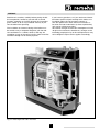
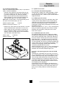
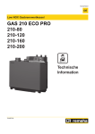
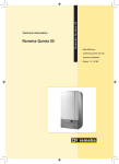
Fig. 01 Artist impression Gas 210 ECO
5
Remeha
Gas 210 ECO
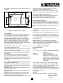
1
GENERAL DESCRIPTION OF THE BOILER
An intelligent, advanced boiler control ('abc®') continuously monitors the boiler conditions, varying the heat
output to suit the system load. The control is able to
react to external "negative" influences in the rest of
the system (flow rates, air / gas supply problems) maintaining boiler output for as long as possible without
resorting to a lock out condition. At worst the boiler
will reduce its output and/or shut down (shut off mode)
awaiting the "negative" conditions to to return to normal
before re-starting.
The 'abc®' control cannot override the standard flame
safety controls.
Every Remeha Gas 210 ECO is checked following
assembly by means of a test computer to ensure its
proper operation.
The boiler meets the requirements of the EC regulations
of the directives:
- 90/396/EEC Gas appliances directive
- 92/42/EEC Efficiency directive
- 89/336/EEC E.M.C. directive
and comply with the following requirements:
- 73/23/EEC Electrical low voltage directive.
- 89/392/EEC Machinery directive.
The Remeha Gas 210 ECO boiler is a pre-assembled,
free standing, gas fired, high efficiency condensing boiler.
The sectional cast aluminium heat exchanger and other
major components are contained within a sealed air
box. This forms the main boiler casing with a removable
front section for maintenance purposes. All electrical and
electronic controls are contained within the instrument
panel mounted on top of the boiler.
The flue gas outlet, combustion air inlet, flow, return and
gas connections are located on the top of the boiler with
a condensate connection at low level on the right hand
side.
The boiler is suitable for room sealed or open flue applications and has been designed for central heating and
indirect hot water production at working pressures not
exceeding 6 bar. It must be installed on a fully pumped
system and is suitable for use on both sealed and open
vented installations (minimum operating pressure open
vented 0.3 bar).
The pre-mix gas burner (NG only) with its gas/air ratio
control system ensures clean, trouble free operation with
higher than average efficiencies 109% (NCV) in the
condensing mode combined with ultra low NOx and
minimum CO emissions. The standard control package
allows actual and set values to be read and adjusted
on the built in digital display which also provides normal
operating and fault code indication.
CE Reference number : 0063 BL 3264.
6
2
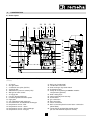
CONSTRUCTION
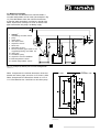
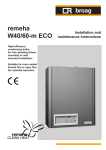
2.1 Boiler layout
12
2
24
1
29
22
23
26
21
27
20
25
3
10
5
16
9
13
8
15
19
11
14
4
6
7
17
18
28
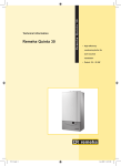
Fig. 02 Cut away view of Remeha Gas 210 ECO (160 kW model shown)
(0021H7900003)
1.
2.
3.
4.
5.
6.
7.
8.
9.
10.
11.
12.
13.
14.
15.
16.
17.
18.
19.
20.
21.
air supply
flue gas outlet
combustion test point (O2/CO2)
sealed air box
differential air pressure switch (LD2)
IMS gas-air ratio control
air supply fan
pre-mix, fibre faced burner
combined ignition/ionisation probe
sight glass
gas combi-block (with governor)
cast aluminium, sectional heat exchanger
temperature sensor - flow
temperature sensor - return
temperature sensor - heat exchanger
temperature sensor - flue gas
22.
23.
24.
25.
26.
27.
28.
29.
7
drain pan (condensate)
condensate connection
heat exchanger inspection hatch
instrument panel
facility for incorporating a rematic® weather
compensator (optional)
boiler setting keys
read-out display and reset key
on/off switch
gas connection
flow connection
return connection
drain cock and optional second return connection
(when fitted)
connection for optional thermostat pocket
(for use with external sequence control)
Remeha
Gas 210 ECO
2.2 Operation principle
Combustion air is drawn into the closed air box through
the air inlet from the plant room (open flued) or from
outside via the eccentric flue system (room sealed) by
an air supply fan.
On the inlet side of the fan is a specially designed
IMS (Integrated Mixing System) gas / air ratio control
unit which takes gas from the combi-block and mixes
it in the correct proportions with the incoming air. This
mechanical mixing system ensures the correct mixture is
delivered to the pre-mix burner at all times.
Depending on demand (under the dictates of flow/return
sensor and other external/internal control inputs) the
‘abc®’ system determines the boiler output, which directly
controls the the volume of mixed gas and air to the
premix burner. This mixture is initially ignited by the
combined ignition/ionisation probe which monitors the
state of the flame. Should the flame be unstable or not
ignite within the pre-set safety time cycle the controls will
(after 5 attempts) shut the boiler down requiring manual
intervention to reset the boiler. The digital display will
indicate a flashing fault code confirming the reason for
the failure.
The products of combustion in the form of hot flue gases
are forced through the heat exchanger transfering their
heat to the system water (the flue gas temperature is
reduced to approximately 5°C above the temperature
of the system return water) then discharged via the
condensate collector, vertically through the 150 mm connection to atmosphere.
Because of the low flue gas exit temperature there will
be a vapour cloud formed at the flue gas terminal - this
is not smoke, simply water vapour formed during the
combustion process.
If the controls allow the flow and therefore return temperature to fall below dew point (55°C) this water vapour
will begin to condense out in the boiler, transfering its
latent heat into the system water, increasing the output
of the boiler without increasing the gas consumption.
Condensation formed within the boiler and flue system
is discharged from the boiler to an external drain via the
drain pan / siphon supplied.
The boiler can be supplied, as an option with a second
(fixed temperature) return connection. This additional
connection enables the boiler to make full use of its condensing ability whilst accepting both fixed and variable
temperature returns from the same system.
8
3
TECHNICAL DATA AND DIMENSIONS
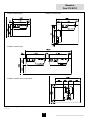
3.1 Dimensions
Fig. 04 View drawings
(0021H7900001)
Flow connection
Return connection
Gas connection
Condensate connection
Flue gas connection
Combustion air supply connection
Second return connection
1¼” BSP (m)
1¼” BSP (m)
1¼” BSP (m)
32 mm o/d (plastic)
150 mm i/d
150 mm i/d
1¼” BSP (m) (optional)
9
Remeha
Gas 210 ECO
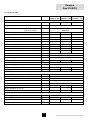
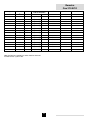
3.2 Technical data
Boiler type
Remeha Gas
210 ECO - 80
Remeha Gas
210 ECO - 120
Remeha Gas
210 ECO - 160
3
4
5
General
Number of sections
qty.
Casing Colour
BS RAL
Boiler control options
(External input)
(Two wire control)
Nominal output (80/60ºC)
2002
On/off, High/low, Analog 0-10V Communicating
Modulation
min.
kW
8
12
16
max.
kW
80
120
160
min.
kW
8.9
13.5
18.1
max.
kW
86
129
171
min.
kW
9.3
14
18.7
max.
kW
90.6
135.6
181.1
min.
kW
8.4
12.6
16.8
max.
kW
81.5
122
163
Weight dry
kg
130
150
170
Noise level at 1 M from boiler, room sealed
dBA
< 57
mbar
17 / 50
Nominal output (40/30ºC)
Nominal input (GCV / Hs)
Nominal input (NCV / Hi)
Gas and Flue
Inlet pressure gas minimum / maximum
3
Gas consumption (natural gas)
m /h
8.6
12.9
17.2
NOx-emission
mg/kWh
< 35
NOx-emission (O2 = 0%, dry)
ppm
< 20
Residual fan duty
Pa
115
100
100
Flue gas mass
kg/h
137
205
274
Water side
Flow temperature
Operating pressure min.
maximum
ºC
110
operating
ºC
20 - 90
open vented
bar
0.3
closed
bar
0.8
max.
bar
6
Water contents
liter
12
16
20
Water resistance at 11ºC ∆t
mbar
496
446
536
Water resistance at 20ºC ∆t
mbar
150
135
162
Electrical
Main supply
Power consumption
Insulation class
Table 01
V / Hz
230 / 1 / 50
min.
Watt
68
58
69
max
Watt
92
84
110
IP
Technical data
10
20
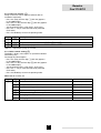
3.4 Optional Accessories
- Modulating weather-compensated / optimising boiler
controls for single and multiple installations
- Thermostat pocket
- Second return connection
- Water pressure sensor
- Air supply filter c/w air supply connecting piece (for
use during building construction)
- Vertical room sealed terminal c/w air supply connecting piece
- Differential pressure sensor to monitor burner and
heat exchanger for blockage
- Indicating module No. 2 indicating operation, boiler on
and high fire (Volt free)
- Interface for RS232 connection, modem communication or communication software (Recom MCBA)
- Interface for communication with several boiler controls
- Valve leak proving system
- Minimum gas pressure switch.
3.3 Quotation specifications
Cast aluminium - sectional pre-mix gas fired boiler
- Sectional heat exchanger manufactured from cast aluminium
- Maximum operating pressure of 6 bar
- Maximum operating temperature of 90°C
- Ultra low NOx (max. 20 ppm @ 0% O2)
- Pre-mix, fully modulating (10-100%) gas burner with
unique IMS gas/air ratio control for maximum efficiency
- Intelligent advanced boiler control ‘abc®’ c/w a comprehensive operating, service and fault diagnostic
facility
- No minimum flow requirement
- Available as conventional flue or room sealed operation
- Capable of remote BMS control (0-10V modulating,
on/off and high/low option)
- Socket for advanced service diagnostics (for PC connection)
- Supplied fully factory assembled and tested
- Powder coated enamel steel casing BS RAL colour
2002
- Sealed air box construction for maximum safety
- Suitable for use with Natural gas
- Supplied as standard with on/off switch, temperature
indication, flow, return, heat exchanger block and flue
gas sensors and hours run indication
- Supplied as standard with indicating module No. 1
lock-out indication (Volt free), shut down indication
(Volt free), boiler on indication (24 Volt AC)
- Efficiencies up to 109% (NCV / Hi)
- Manufactured to ISO 9001
- CE approved.
11
Remeha
Gas 210 ECO
4
EFFICIENCY INFORMATION
4.1 Annual efficiency
Up to 108.2% at Hi (up to 97% at Hs) at an average
water temperature of 35°C (40/30°C).
4.3 Standing losses
On average 0.3% at Hi (0.33% at Hs) at an average
water temperature of 45°C.
4.2 Heat to water efficiency
a. Up to 98% at Hi (88% at Hs) at an average water
temperature of 70°C (80/60ºC).
b. Up to 109% at Hi (98% at Hs) at an average water
temperature of 35°C (40/30ºC).
Note: NCV = Hi, GCV = Hs
5
APPLICATION INFORMATION
The Gas 210 ECO can be used on all new and refirbishment projects in both single and multiple configurations. Conventional and room sealed flue system
capability means that the boiler can be sited almost
anywhere within a building.
The Remeha range of weather compensators (options)
are able to communicate directly with the boiler controls
to make full use of its fully modulating feature, ensuring
that the boiler closely matches the system demand at all
times. External control systems (BMS) can be interfaced
with the boiler to provide on/off - high/low or modulating
(0-10V) control options.
12
6
CONTROL AND SAFETY EQUIPMENT
6.1 The instrument panel
6.1.2 Layout of the instrument panel
The instrument panel consists of the following components (see Fig. 05 and Table. 02):
1. On/off switch
2. PC-connection
3. Facility for incorporating a rematic® weather
compensator.
6.1.1 General
The boiler is supplied with a standard set of defaults preprogrammed for normal operation but can be tailored by
the Engineer to suit most site conditions. These values
are set and read using the built in control panel or
with a note book computer (with optional software and
interface).
For security the control has three levels of access :
1. user level
- free access
2. service level - access with service code by qualified
personnel
3. factory level - access by PC with factory code
(Remeha only).
The functions of keys and displays (letters a - h) are
explained in Table. 02.
Fig. 05 Instrument panel
(0021H7900016)
13
Remeha
Gas 210 ECO
a. code-display
Indicates on user level:
Additional indication on service
level:
operating mode
- 1 digit or letter
setting mode
- ! digit or letter with dot
read-out mode
- ! digit or letter with flashing dot
shut-off mode
- letter b
forced full load
- letter h
forced part load
- letter l
test phase IMS
- letter t
failure mode
- 1 digit flashes
boiler run information mode - successively 1 + , + .
b. t-display
Indicates:
temperatures
settings
shut-off codes
lock-out codes
c. reset-key:
to reset boiler after a lock-out
d. m-key:
program function: key to select the required mode (mode-key)
e. s-key:
program function: key to select the required program within the selected mode
(step-key)
f. e-key:
program function: key to save the settings (store-key)
g. [+]-key:
program function: to select a higher setting
h. [-]-key:
program function: to select a lower setting
h. [-]-key held for 2 seconds
switch function: manual override (hand/auto)
Table 02
Instrument panel functions
6.1.3 Indication LED’s
The instrument panel has three indicating LED’s.
1. The LED above the [-]-key (in the h-symbol) when
illuminated green confirms the boiler is in manual
override (see par. 6.1.4).
2. The LED above the [+]-key (in the 0-symbol) when
illuminated green confirms that the IMS system is
completely closed (rest position).
3. The LED above the e-key when illuminated red
(flashing) confirms that the differential pressure sensor has identified a need for the burner and/or heat
exchanger to be cleaned. This function is only available if the optional differential pressure sensor is
fitted (see par. 8.7.3).
Hand/auto
When the [-]-key is pressed and held for 2 seconds the
boiler will run, even if external controls are not calling for
heat. The green LED above this key (in the h-symbol)
will illuminate indicating manual override.
By pressing and holding for 2 seconds the [-]-key, the
boiler will return to normal (auto control).
Attention: A (system) pump which isn’t connected to
the terminal strip of the boiler control, will not be
activated!
Forced mode ‘high’ (h [[)
By pressing the m and [+]-key simultaneously in operating mode during 2 seconds, the boiler will run at
maximum power. The letter h will now appear on the
display.
By pressing the [+]- and [-]-keys simultaneously, the
boiler will return to operating mode.
Following a manual override the boiler will return to
normal (auto control) if no keys are used within a 15
minute period.
6.1.4 Manual override (hand/auto or forced modes
‘high’ and ‘low’)
Some of the keys on the instrument panel have a double
function.
- Normal function - program input (see par. 6.5 and 6.6)
- Manual override - (during these modes as described
below the flow temperature cannot exceed its pre-set
maximum).
14
Forced mode ‘low’ (l [[)
By pressing the m and [-]-key simultaneously in operating mode, the boiler will run at minimum power. The
letter l will now appear on the display.
By pressing the [+]- and [-]-keys simultaneously, the
boiler will return to operating mode.
Following a manual override the boiler will return to
normal (auto control) if no keys are used within a 15
minute period.
- values from 100 to 199 will be indicated by a dot
between both digits e.g. )0 = 100, !0 = 110,
(9 = 199
- values from 200 to 299 will be indicated by a dot
behind every digit e.g. )) = for 200, !) = 210,
(( = 299
- values over 300 will be indicated by showing the
thousands, hundreds, tens and units in separate alternating pairs.
6.1.5 Display of values with more than two digits
The display has only two digits available therefore values
over this are displayed as follows :
- negative values will be indicated by a dot behind the
last digit e.g. 1) = -10
- values from 00 to 99 will be indicated without any
punctuation marks
6.2 Flow diagram control system
Operating mode,
see par. 6.3
press the m-key
press the s-key
code-display
t-display
only digit or letter
0 - 9, h, l, b, t
Setting mode,
see par. 6.5 and
6.6
* Note: Only active when optional module/sensor
is fitted.
Flow temperature, shut-off code
digit or letter with dot
!
Flow temperature set point
@
Pump run on time
A
Boiler control setting
service engineer level only:
$
Low fire start point as percentage
%
Boiler output as % to indicate high fire*
^
Maximum output
&
Forced part load
*
Forced part load running time
(
Cycling prevention delay-time
a
Start point for 0 Volt analog signal
B
End point for 10 Volt analog signal
C
n/a
D
n/a
E
∆t from control stop point to start point
F
n/a
G
High limit temperature set point
H
Modulation start point ∆T
I
Minimum water pressure*
15
Remeha
Gas 210 ECO
Read-out mode,
see par. 6.7
J
Adjustments options/accessories
L
n/a
P
Boiler type, factory set
digit or letter with flashing dot
!
Actual flow temperature
@
Actual return temperature
#
Actual flue gas temperature
$
Actual outdoor temperature (with outside temperature sensor)
%
Actual heat exchanger temperature
^
Flow temperature (setpoint)
&
Actual heat demand status and differential air pressure switch
position
Failure mode,
see par. 6.8
Counter mode,
see par. 6.9
Table 03
*
Actual open to close time IMS
(
Requested output
A
Calculated or actual output
B
Status IMS
C
Actual valve position IMS
D
Actual water pressure*
E
Actual ∆p over burner and heat exchanger*
F
Actual fan speed
G
Actual ionisation level
H
Minimum position IMS
digit flashes
digits flash
1
Failure code (chapter 10)
2
Operating mode
during failure (par. 6.3)
3
Flow temperature
during failure
4
Return temperature
during failure
5
Flue gas temperature
during failure
6
Position of IMS
during failure
digit + , + .
digits flash
1, ,, .
Number of operating hours burner
2, ,, .
Number of successful ignition attempts
3, ,, .
Total number of start attempts
Flow diagram control system
16
6.3 Operating mode (x [[)
During normal operation the code-display shows the
status (position in cycle) of the boiler, with the t-display indicating the actual flow temperature.
The digits or letters in the code-display have the
following meaning:
0
Standby; there is no heat demand from control system or IMS is moving to maximum
1
Pre-purging (12 seconds)
2
Ignition
3
The burner is firing
5
Waiting mode; the fan runs and the boiler waits until sufficient air transport is established (air pressure
switch open or closed)
6
Normal control stop during heating:
- flow temperature > setpoint + 5 °C
- flow temperature > desired setpoint modulating control + 5 °C
- flow temperature > 95 °C
7
Pump overrun time
b
Shut-off mode
h
Forced full load
l
Forced part load
t
Test phase IMS (when no signal is being observed by the control unit: in total 3 attempts before lock-out)
Table 04
Operating codes
6.4 Shut-off mode (b XX)
During shut-off mode condition the code-display will
show a b, whilst the t-display indicates the cause
with two flashing dots.
Table below details cause of shut-off mode.
Code
Description
Cause/control points
b
Insufficient air transport during pre-purge. After 5 attempts
the boiler will go to lock-out code 08 (see par. 10.2).
Check:
)*
- flue gas discharge/air supply for
clogging
- air pressure switch and connections.
B
B
@$
@%
Return temperature is higher than flow temperature. If the
boiler registers a higher return temperature than flow, it will
modulate to minimum set point and run for 10 minutes. If
return temperature remains higher than the flow the boiler
will shut-down and wait for return temperature to fall below
flow temperature.
- Flow and return sensors wiring
reversed
Flow temperature rate of rise exceeded. The boiler will shutoff for ten minutes, then restart. Should the rate of
temperature rise remain the same after 5 start attempts
(within one heat demand cycle), this code will be recorded
as a shut-down failure and cycle repeated.
Check:
17
- Flow and return connections
reversed.
- system full of water and under
pressure
- pumps are running
- water flow through the boiler.
Remeha
Gas 210 ECO
B
B
B
@^
#)
$#
If minimum gas pressure switch is connected (option) and
pressure is below minimum set point. Boiler shuts down for
10 minutes. The boiler will try again, if gas pressure is still
below minimum it will shut down again and repeat the cycle
until pressure is re-instated.
- Check gas supply
Flow / return ∆t factory-set maximum exceeded. The boiler
will shut off for 150 seconds, then restart. Should the ∆t
conditions remain the same after 20 attempts (within one
heat demand cycle), this code will be recorded as a shut
down failure and the cycle repeated.
Check:
One or several adjusted parameters out of range including
some factory defaults which should not have been changed.
Reset parameters.
- Is gas valve open?
- Check set value of the gas pressure
switch
- Check wiring.
- system full of water and under
pressure
- pumps are running
- water flow through the boiler.
Press the reset-key directly followed by
pressing and holding the m-key for 5
seconds.
Code display shows P.
Enter correct boiler type parameter,
see table in par. 6.6.
B
B
%@
^@
Maximum flue gas temperature set point is exceeded. Boiler
shuts down for 150 seconds, then restarts. This cycle is
repeated if necessary.
Check:
When boiler exceeds maximum flue gas temperature with
5°C, the boiler will go to lock-out code 52 (see par. 10.2).
- if the heat exchanger is clean.
- the flue gas temperature set point
- the gas/air settings
If water pressure sensor is connected (option) and pressure Check:
is below minimum set point. Boiler will shut down and restart - system pressure
only if water pressure is re-instated.
- minimum water pressure set point
- sensor
- wiring.
B
**
External interlock has opened. When the interlock closes,
the control stop or shut-off mode is cancelled.
Cancel the shut-off by removing the
cause.
B
($
Heat exchanger and flow temperature ∆t is exceeded (5°C).
Boiler shuts down for 10 minutes then restarts. Should the
∆t conditions remain the same after 5 successive attempts
within one heat demand cycle, this code will be recorded as
a shut down failure and the cycle repeated.
Check:
Table 05
Shut-off codes
Note: Shut-off mode is a normal boiler operating
function and does not represent a boiler failure.
However, this may indicate a system problem or an
incorrect parameter setting.
18
- system full of water and under
pressure
- pumps are running
- water flow through the boiler.
6.5 Setting mode user level (X [[)
Code
Description
Setting range
!
Flow temperature set point
20 - 90ºC
@
Pump run on setting
00
Preset
80
= pump run on 10 seconds
01 - 15 = pump run on in minutes
99
A
Table 06
Boiler control setting
03
= continuous pump operation
31
Control mode (modulating-on/off-etc.)
Settings mode user level
Note: Changing @ and A should only be on design
engineers advice.
6.5.1 Flow temperature set point (!)
The required flow temperature is adjustable from 20 to
90ºC (factory setting 80°C).
The following diagram shows a typical example of this
procedure:
Code
Code
Reset
Reset
Set required flow temperature with the '+' and '-' -key
Find code 1.
(digit and dot)
1x
Code
Reset
Code
Reset
1x
Store the new setting
Return to operating mode
Fig. 06 Adjusting maximum flow temperature
19
Remeha
Gas 210 ECO
6.5.2 Pump run on time (@)
Pump run on time can be adjusted (Please refer to
installation contractor).
- Press the m-key until the digit ! (with dot) appears
in the code-display.
- Press the s-key until the digit @ (with dot) appears
in the code-display.
- Set the required value, using the [+]- and [-]-keys.
- Press the e-key to store the new value (value will
flash twice).
- Press the reset-key to return to operating mode.
Code
t
Description
@
00
Pump runs on for 10 seconds
@
xx
Pump runs on for 1 to 15 minutes (xx = 01 to 15)
@
99
Continuous pump operation
Table 07
Adjustments pump run on time
6.5.3 Boiler control setting (A)
The boiler is factory set to option 31 (On/Off-modulation
with heating On).
To change the control option:
- Press the m-key until the digit ! (with dot) appears
in the code-display.
- Press the s-key until the digit A (with dot) appears
in the code-display.
- Set the required value, using the [+]- and [-]-keys.
- Press the e-key to store the new value (value will
flash twice).
- Press the reset-key to return to operating mode.
Note: Booster function n/a
Code
A
Table 08
t
Description
x0
Heat demand off
x = 1, 2, 3, 4 or 5
x1
Heat demand on
x = 1, 2, 3, 4 or 5
1y
On/off, modulating on flow temperature with booster function
y = 0 or 1
2y
High/low, modulating on flow temperature
y = 0 or 1
3y
On/off, modulating on flow temperature without booster function
y = 0 or 1
4y
Analog signal 0-10V on temperature
y = 0 or 1
5y
Analog signal 0-10V on output %
y = 0 of 1
Boiler control setting
20
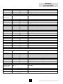
6.6 Setting mode service level (only for the qualified
service engineer) (X [[)
To prevent accidental, unauthorised access by non-qualified persons the control system requires an input code
to gain access to the second level of boiler control.
- Press the m- and s-keys simultaneously and hold.
The code-display now shows a letter c with a random number in the t-display.
- While holding both keys pressed, set the t-display
to 12, using the [+]- or [-]-keys and press the
e-key.
- The display will flash twice confirming acceptance of
the access code.
- Release the keys and c12 will dissappear from
the display.
Code
You are now in the service mode.
WARNING: changing the pre-set values without reference to the tables contained in this manual may
result in incorrect boiler operation.
- The service settings can now be reached by pressing
the m-key until the digit ! (with dot) appears in
the code-display. Set the required value, using the
s-key.
- To delete the service code press the reset-key once.
- If no keys are pressed over a 15 minute period the
service code will delete automatically.
Description
Setting range
Pre-set
$
Low fire start point, par. 6.6.1
00 - )0 (=100) (% output)
50
%
Boiler output to indicate high fire, par.
6.6.2
00 - )0 (=100) (%)
90
^
Maximum output, par. 6.6.3
50 - )0 (=100) (%)
)0 (=100)
&
Forced part load, par. 6.6.4
10 - 50 (% output)
30
*
Forced part load running time, par.
6.6.4
00 - 30 (x 10 sec.)
02 (80 kW) and 01
(120 kW and 160 kW)
(
Cycling prevention delay-time, par.
6.6.5
00 - 30 (x 10 sec.)
02 (=20 s.)
a
Start point for 0 Volt analog signal,
par. 6.6.6
5) (=-50) - 50 (°C)
00
B
End point for 10 Volt analog signal,
par. 6.6.6
50 - ((
)0 (=100)
C
n/a, par. 6.6.7
10 - )0 (=100) (%)
)0 (=100)
D
n/a, par. 6.6.7
10 - )0 (=100) (%)
30
E
∆t from control stop point to start
point, par. 6.6.8
05 - 20 (°C)
10
F
Maximum flue gas temperature, par.
6.6.9
80 - @0 (=120) (°C)
@0 (=120)
G
High limit temperature set point, par.
6.6.10
90 - !0 (=110) (°C)
!0 (=110)
H
Modulation start point ∆T, par. 6.6.11
10 - 30 (°C)
25
I
Minimum water pressure, par. 6.6.12
00 - 60 (x 0,1 bar)
08 (=0,8)
J
Adjustments options/accessories, par. 00 - 15 (see Table. 10)
6.6.13
L
n/a, base point internal compensation
slope, par. 6.6.14
15 - 60 (°C)
P
Boiler type, factory set, for reference
only, par. 6.6.15
Gas 210 ECO, 80 kW
(=299) (°C)
20
: 10
Gas 210 ECO, 120 kW : 20
Gas 210 ECO, 160 kW : 30
Table 09
Settings service level
21
00
Dependent of boiler type
Remeha
Gas 210 ECO
6.6.1 Low fire start point ($)
Adjustable from 0 to 100%, factory setting 50%.
The value relates to the low fire output set point in
percent of total.
Note: Only active when boiler control option 21 is
choosen: high/low, modulating on flow temperature, see
par. 6.5.3.
100
desired flow temperature (°C)
90
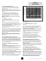
6.6.2 Boiler output to indicate high fire (%)
Adjustable from 0 to 100%, factory setting 90%.
This value sets the point (in %) which indicates the
boiler is at high fire.
Note: Only active when optional Volt free module No.
2 is fitted.
80
70
60
50
40
30
20
10
0
0
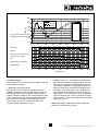
6.6.3 Maximum output (6)
Adjustable from 50 to 100% output, factory setting
100%.
This value sets the maximum output of the boiler.
1
2
3
4
5
6
7
8
9
10
input voltage (V) - DC
Fig. 07 Temperature control via analog
(0-10 Volt) signal
6.6.4 Forced part load and running time (& en *)
Forced part load, parameter &, adjustable from 10 to
50% input, factory setting 30%.
This value will force the boiler to always start at this
percentage i.e. 30%.
6.6.7 PWM pump position (C and D)
n/a to UK.
6.6.8 ∆t from control stop point to start point (E)
Adjustable from 5 to 20°C, factory setting 10°C.
This value sets the flow temperature at which the boiler
will cut back in after a control stop.
The boiler will always go to a control stop when the
flow temperature equals the flow set point temperature
+ 5°C.
Cut back in temperature = flow set point (80) + 5 parameter E (10), i.e. 80 + 5 - 10 = 75°C.
Forced part load running time, parameter *, adjustable
from 0 - 300 sec., factory setting 20 sec. for the 80 kW
boilers and 10 sec. for the 120 and 160 kW boilers.
This value sets the time the boiler stays on forced start
level i.e. 20 sec.
Note: If both values are set to 0 or the time period
expires the boiler will revert to what ever the system is
demanding.
6.6.9 Maximum flue gas temperature (F)
Adjustable from 80 to 120°C, factory setting 120°C.
This value sets the maximum operating flue gas temperature - for use with PVC flue systems.
6.6.5 Cycling prevention delay-time (()
Adjustable from 0 and 300 sec., factory setting 20 sec.
This value sets a minimum off time following a control
stop / end of a heat demand to prevent cycling taking
place. When after this delay time flow temperature lies
less than 5°C above return temperature (check on water
flow), the boiler will restart.
6.6.10 High limit temperature set point (G)
Adjustable from 90 to 110°C, factory setting 110°C.
This value sets the high limit temperature at which the
boiler will shut down in a lock out condition requiring
manual intervention.
Note: If the factory setting is reduced, a corresponding
reduction in flow set point will be required otherwise the
min flow rate may be effected.
6.6.6 Start and end point for analog signal
(a and B)
Start point (0 Volt): parameter a, adjustable between
-50°C and +50°C, factory setting 0°C.
This value sets the required flow temperature at 0 volt
signal input (restricted by the min IMS set point).
6.6.11 Modulation start point ∆T (H)
Adjustable from 10 to 30°C, factory setting 25°C.
This value sets the flow/return ∆t point at which the
control modulation begins. The factory set point should
be correct for most installations.
Note: The boiler starts to modulate at the set point and
will be at minimum output if the ∆T continues to rise to
40°C. At 45°C the boiler will shut-off (shut-off code b
#)). For installations with low flow rates the starting
point modulation can be brought forward (i.e. 15°C),
closer matching boiler output to system demand.
End point (10 Volt), parameter B, adjustable between
+51°C and +299°C, factory setting 100°C.
This value sets the required flow temperature at 10 volt
signal input (restricted by the maximum flow temperature
set point and the maximum output).
Note: These settings are only applicable when parameter 41 is chosen for the boiler control operation.
22
6.6.12 Minimum water pressure (I)
Adjustable from 0 to 6 bar, factory setting: 0.8 bar.
This value sets the point at which the boiler will shut
down if the system pressure falls below it. The boiler will
resume normal operation when pressure is restored.
Note: Only active when optional water pressure sensor
is fitted.
6.6.14 Base point internal compensation slope (L)
n/a to UK.
6.6.15 Boiler type (P)
Factory default, should not be changed.
Three possible settings 10, 20 or 30, factory setting
dependant on the output.
This value sets the boiler type and output and should
only be changed when fitting a replacement control
module or after reference to Broag’s service department.
6.6.13 Adjustments options/accessories (J)
Adjustable from 0 to 15, factory setting 0.
This value is only applicable when options as listed are
fitted to the boiler.
Options
6.7 Read-out mode (X [[)
To check boiler set points and values.
Press the m-key until ! (flashing dot) appears in the
code-display. Then select the required code @, # or
$ etc. using the s-key.
Value
Water pressure sensor
01
Air pressure sensor
02
Analog output:
Output (%)
00
Temperature (°C)
04
Valve leak proving system
08
Parameter J:
Table 10
Adjustments options/accessories
Examples:
- Factory setting is 0: the analog output will be in %.
- Water pressure sensor (1) and valve leak proving
system (8) options are connected: parameter J is set
to (1) + (8) = 09.
- Air pressure sensor (2) connected and analog
output as temperature (4): parameter J is set to
(2) + (4) = 06.
23
Remeha
Gas 210 ECO
Description
Read-out range / remarks
Read-out
(example)
!
Flow temperature (°C)
actual value
80
@
Return temperature (°C)
actual value
70
#
Flue gas temperature (°C)
actual value
85
$
Outdoor temperature (°C)
with outside temperature sensor:
e.g. 05
without outside temperature sensor:
3% (= -35)
Code
%
Heat exchanger temperature (°C)
actual value
75
^
Flow temperature (set point) (°C)
calculated value
84
Status heat demand (1 digit) and
differential air pressure switch (LD2,
nd
2 digit)
0x = no heat demand, 1x = heat
demand
11
Open to close time IMS (÷50 for
seconds)
actual open to close value, 00 1250*
10
Requested output (%)
required value by external analog signal
(par. A = 5x)
90
&
*
(
st
x0 = open, x1 = closed
(heat demand /
closed)
00 (=1000*)
00 - )0 (=100)
A
Calculated output (%)
calculated value, 10 - )0 (=100)
87
B
Status of IMS
calculated position,
01
00 = IMS closed
01 = IMS min. - 99%
02 = IMS fully open
C
Valve position IMS (%)
actual value, 00 - )0 (=100) %
90
D
Actual water pressure (÷10 for bar)
00 - 60, only with water pressure
sensor
15
without water pressure sensor
0)
actual value XX, only with differential
pressure sensor
> XX service
required
without differential pressure sensor
0)
actual value, 00 - 6000*
40
E
F
∆p over burner and heat exchanger
Fan speed
00 (=4000*)
G
Ionisation level
actual value,
03
00 = smaller than 2 A
01 = larger than 2 -A
02 = larger than 3 -A
03 = larger than 4,5 A
04 = larger than 6 -A
H
Minimum position IMS (÷100 for %)
actual value, 00 - 1000*
10
00 (=1000*)
Table 11
Read-out mode user level
* The displayed value has 4 digits. The display alternately flashes from F 40 to . 00 with code
indicating the value being read. In this example:
fan speed 4000 r.p.m.
24
6.8 Failure mode (x [[) (service level)
An actual failure is recognizable to a flashing code- and
t-display (see Table. 23 in 10.2).
The latest failure with the accompanying operating
codes and relevant temperatures are being stored and
can be read out as follows.
Gain access to the service level by entering the service
code c 12 (see par. 6.6).
Press the m-key until 1 appears in the code-display
(digit flashes).
Then select the required code 2, 3 or 4 etc. using
the s-key and read off the relevant value.
Code
t
Description
1
37
Failure code (see chapter 10)
2
03
Operating mode
during failure (see par. 6.3)
3
53
Flow temperature
during failure
4
40
Return temperature
during failure
5
58
Flue gas temperature
during failure
6
67
Position of IMS
during failure
Table 12
Failure mode on service level
Example as above :
Failure code 37 (flashing) - indicates the return temperature sensor has failed during operation (03), at
a flow temperature of 53°C, a return temperature of
40°C and a flue gas temperature of 58°C, with the
IMS system 67% open.
6.9 Counter mode (1, , and .) (service level)
First of all gain access to the service level by entering
the service code c 12 (see par. 6.6).
6.9.1 Hours Run
Press the m-key until the code-display shows successively 1, , and .. This will alternate with three sets
of two digits displaying the number of hours as table.
Code
Description
Eg. 14403 hours
1
Hours run in hundred thousands and ten thousands
01
,
Hours run in thousands and hundreds
44
.
Hours run in tens and units
03
Table 13
Hours run meter
6.9.2 Successful ignition attempts
To read the number of successful ignition attempts.
Press s-key once code-display changes to 2, ,
and .. This will alternate with three sets of two digits
displaying the number of successful ignition attempts as
table.
25
Remeha
Gas 210 ECO
Code
Description
Eg. 8765 attempts
2
Successfull ignition attempts in hundred thousands and ten
thousands
00
,
Successfull ignition attempts in thousands and hundreds
87
.
Successfull ignition attempts in tens and units
65
Table 14
Meter successful ignition attempts
6.9.3 Total start attempts
To read the total number of start attempts. Press
s-key once code-display changes to 3, , and ..
This will alternate with three sets of two digits displaying
the number of start attempts as table.
Code
Description
Eg. 8766 attempts
3
Total start attempts in hundred thousands and ten thousands
00
,
Total start attempts in thousands and hundreds
87
.
Total start attempts in tens and units
66
Table 15
Meter total number of starts attempts
26
7
INSTALLATION INSTRUCTIONS
7.1 General
All gas appliances must, by law, be installed by competent persons (e.g. Corgi). Failure to install appliances
correctly could lead to prosecution.
It is in your own interest and that of safety to ensure that
the law is complied with.
7.2 Delivery, positioning and support surface
The Remeha Gas 210 ECO is supplied as standard fully
assembled, plastic wrapped, crated on a pallet (70x120
cm), which can be easily moved with a pallet or hand
truck. The standard package will pass easily through all
standard doorways (min. 745 mm).
Within the crate there is a Poly Styreen protective cap
which contains the boiler documentation, boiler support
strips and accessories when supplied.
The following instructions must be adhered to when the
Remeha Gas 210 ECO is installed:
- Gas Safety (Installation and Use) Regulations 1984
(as amended).
In addition to the above regulations, this boiler must be
installed in compliance with:
- Current I.E.E. Regulations for electrical installations
- Local building regulations
- The Building Standards (Scotland)
- (Consolidation) Regulations
- by-laws of the local water undertaking
- Health and Safety Document No 635 ‘The Electricity
at Work Regulations 1989’.
It should also be in accordance with the relevant recommendations in the current edition of the following British
Standards and Codes of Practice, viz. BS 5440 Pt 1 and
2, BS 5449, BS 5446, BS 6798, BS 6891 and BG DM2.
The Remeha Gas 210 ECO boiler should be positioned
as follows:
- Place the pallet c/w boiler in the plant room adjacent
to final location.
- Remove straps, crate, top and sides and all other
packaging.
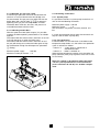
- Slide the boiler assembly off the pallet, making use
of the molded ‘hand holdes’ in the drain pan base,
taking care to lift clear of the retaining blocks.
- Slide the boiler assembly into its final position.
- Locate the support strips (in Poly Styreen cap), place
the three strips in the locating slots in the base of
the drain pan (across the boiler, see Fig. 04, front
view).
- Remove the front casing to gain access to the leveling
bolts in the base of the drain pan.
- Level the boiler using a spirit level on the top of the
drain pan.
- Replace the front casing and using the Poly Styreen
caps and plastic sheeting cover boiler to protect
from dust and dirt, etc.
Important:
The Remeha Gas 210 ECO is a CE certified boiler and
must not be modified or installed in any way contrary to
these “Installation and Maintenance Instructions”.
Manufacturers Instructions must NOT be taken as overriding statutory obligations.
The following minimum clearances are recommended:
Front: 600 mm.
Top: 400 mm.
Left side: 50 mm.
Right side: 250 mm.
27
Remeha
Gas 210 ECO
1 Boiler in boiler room
2 Boilers in boiler room
2 Boilers in boiler room
2 Boilers in boiler room, back to back
Fig. 08 Positioning possibilities in the boiler room
(0021H7900020)
28
The following drawing represents the support surface of
the boiler.
rate ducts for the air supply and flue gas discharge,
terminated in zones of different pressure.
Type C63: Room sealed appliance, suplied without the
terminal or the air supply and flue gas discharge ducts.
Conventional open flue installation:
Combustion air for the boiler must be provided to the
room/compartment in accordance with BS 6644.
For maximum flue length see table in par. 7.3.4.
Room sealed installations:
It is unnecessary to provide separate combustion air to
the room/compartment as this is supplied direct to the
boiler via the eccentric system and the room sealed horizontal (min discharge height of 5M) or vertical terminal
unit.
Fig. 09 Support surface Remeha Gas 210 ECO
Additional ventilation will be required to the room/
compartment in accordance with BS 6644 (compartment
ventilation).
For maximum flue/air inlet length see table in par. 7.3.5.
(0021H7800001)
7.3
Flue gas discharge and air supply
7.3.1 General
The Remeha Gas 210 ECO is suitable for conventional
room ventilated or room sealed operation. Specify at
the time of ordering if the boiler is to be supplied
for room sealed operation. In that case, the boiler will
be supplied with a purpose designed room sealed terminal, air supply connection and some accessories.
The air supply connection should rest on the heat
exchanger underneath the boiler casing after removing
the standard perforated air inlet cover.
For installations where supply and discharge points are
in two different pressure zones CLV system please contact Broag Technical Dept. for further details and advice.
See also par. 7.3.6.
Note: the boilers can be installed on a flue dilution
system, but must have a total flue break to avoid boiler
controls being affected by the flue dilution fan pressures.
For full details please contact Broag.
7.3.3 Material and installation
Flue gas discharge:
Material:
Rigid single walled : stainless steel (316), aluminium
or plastic (to comply with building
regulations).
Flexible
: stainless steel (316).
Construction
: all joints and seams should be
gastight and watertight with the
horizontal runs graded towards the
boiler (min. discharge 5 cm per M)
to allow condensate free drainage
to the boiler.
Horizontal components in the flue gas discharge system
should slope towards the boiler.
Horizontal components in the air supply system should
slope towards the supply opening.
Room sealed terminals should comply with the Gastec
QA-requirements for both horizontal and vertical outlet
constructions.
Care should be taken when siting flue exit positions
as a vapour plume will be visible when the boiler is
operational (flue gas temperature will be less than 75°C
resulting in the water vapour condensing out on contact
with the air).
7.3.2 Classification due to discharging flue gases
Classification according to CE:
Type B23: Conventional room ventilated appliance without draft diverter. Air supply from boiler room; flue gas
discharge on roof.
Type C13: Room sealed appliance, connected to combined horizontal terminal.
Type C33: Room sealed appliance, connected to combined roof outlet.
Type C43: Room sealed appliance in cascade configuration, connected via two ducts to a common duct
system serving more than one appliance.
Type C53: Room sealed appliance, connected to sepa-
When stainless steel or plastic ducting are being applied, an extra condensate discharge has to be installed
in the flue just above the boiler. This also obtains when
the flue piping has a length of more than 3 m.
The flue outlet should terminate with reduction cone and
bird guard only (chinamans hat or GLC type terminals
etc. should not be used).
Air supply:
Material:
Single walled, rigid or flexible: aluminium, stainless
steel and plastic (to
comply with building
regulations).
29
Remeha
Gas 210 ECO
7.3.4
7.3.5
Single boiler conventional flue
Single boiler, room sealed flue
Fig. 10 Flue gas discharge duct without bends, single
boiler, conventional flue.
Fig. 11 Flue gas discharge duct without bends, single
boiler, room sealed application.
(0021H7900017) (nr 1)
(0021H7900017) (nr 5)
Flue diameter
Model Gas 210 ECO
max eq. length L
m
eq. length bend
45°, R=D
m
eq. length bend
90°, R=D
m
Table 16
150 mm
Flue/air inlet diameter
150/150 mm
80 kW - 120 kW - 160 kW 3
4
5
Model Gas 210 ECO
80 kW - 120 kW - 160 kW 3
4
5
160
70
37
max eq. length L
m
1.2
eq. length bend
45°, R=D
m
1.2
2.1
eq. length bend
90°, R=D
m
2.1
Table 17
Calculation data conventional flue
82
33
16
Calculation data room sealed applications
Example: Gas 210 ECO, 160 kW - 5 sections, total
length 15 m, 2 bends 90°.
15 m + 2 x 2.1 = 19.2 < 37 m → flue OK.
Example: Gas 210 ECO, 120 kW - 4 sections, total
length flue 25 m, 2 bends 90°.
25 m + 2 x 2.1 = 29.2 < 33 m → flue OK.
Note: If the design parameters are outside the values
shown in the above table or there is any doubt
over the flue system, please contact our technical
department for calculation to be undertaken.
Note: If the design parameters are outside the values
shown in the above table or there is any doubt
over the flue system, please contact our technical
department for calculation to be undertaken.
30
Flue/air inlet diameter
150/150 mm
Model Gas 210 ECO
80 kW - 120 kW - 160 kW 3
4
5
maximum total
length of air inlet
and flue gas outlet
pipework L
m
112
42
eq. length bend
45°, R=D
m
1.2
eq. length bend
90°, R=D
m
2.1
Table 18
18
Different pressure zones
Note: this system may not be used in areas with adverse
wind conditions (i.e. in some coastal regions).
Note: If the design parameters are outside the values
shown in the above table or there is any doubt
over the flue system, please contact our technical
department for calculation to be undertaken.
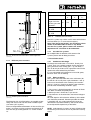
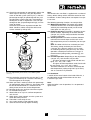
7.3.7 Cascade flue systems
For multiple boiler installations with common flue
systems please refer to Broag for advice.
Fig. 12 Vertical terminal for room sealed operation
(0021H7900006)
7.4 Installation details
7.3.6
Different pressure zones
7.4.1 Condensate discharge
Discharge the condensate via a tundish, directly into
a drain. Only use synthetic material for the connecting
piping, because of the acidity (pH 2 - 5) and allow a
min. of 30 mm per M to ensure a good flow rate. Fill the
siphon with water before firing the boiler.
It is not adviseable to discharge into an outside gutter,
because of the risk of freezing.
7.4.2 Water treatment
The system should be filled with mains cold water (for
the UK this will usually have a pH of between 7 and 8).
Pressurised installations with a boiler/system content
ratio of 1:10 or less should not require water treatment,
provided that the following conditions apply:
1. The system is flushed thoroughly to remove all fluxes
and debris and filled completely once.
2. Make up water is limited to 5% per annum.
3. The hardness of the water does not exceed 360 ppm
(20°D).
All scale deposits will reduce the efficiency of the boiler
and should be prevented. However provided the above
is complied with any scale produced will not be too
detrimental to the boiler efficiency and will not reduce
the anticipated life expectancy of the boiler.
Fig. 13 Different pressure zones
(0021H7900021)
The Remeha Gas 210 ECO boilers are capable of operating with the air inlet and flue outlet in different pressure zones (CLV System).
The max height difference between air inlet and flue gas
outlet is 36 meters and the maximum total length of air
inlet and flue gas outlet pipework L is shown in Table.
18.
NOTE: Scale deposits in excess of 5mm will reduce boiler efficiency and increase the risk of premature casting
failure.
31
Remeha
Gas 210 ECO
As most systems contain a variety of metals it is considered good practice to provide some form of water
treatment (especially in open vented systems) in order to
prevent or reduce the following.
- Metallic corrosion
- Formation of scale and sludge
- Microbiological contamination
- Chemical changes in the untreated system water.
If water treatment is used, we recommend the following
products:
‘Copal’ manufactured by:
Fernox Manufacturing Company Ltd.
Britannia Works
Clavering
Essex, CB1L 4QZ
Tel No: 0179 955 0811
Fax No: 0179 955 0853
Suitable chemicals and their use should be discussed
with a specialist water treatment company prior to carrying out any work. The specification of the system
and manufacturers recommendations must be taken into
account, along with the age and condition of the system.
New systems should be flushed thoroughly to remove all
traces of flux, debris, grease and metal swarf generated
during installation. Care to be taken with old systems to
ensure any black metallic iron oxide sludge and other
corrosive residues are removed, again by thoroughly
flushing, ensuring that the system is drained completely
from all low points.
or:
Sentinal ‘X100’ manufactured by:
BetzDearborn Ltd
Sentinal
Foundry Lane
Widnes
Cheshire WA8 8UD
Tel No: 0151 424 5351
Fax No: 0151 420 5447.
NOTE: Please ensure that the new boiler plant is not
in circuit when the flushing takes place, especially if
cleansing chemicals are used to assist the process.
For the correct dosage and for further information on
water treatment or system cleaning we advise direct
contact with either of the above companies.
Under no circumstances is the boiler to be operated
with cleaning chemicals in the system.
7.4.3 Safety valve
A safety valve should be fitted in accordance with BS
6644.
Recommended minimum size of 28mm (full bore type).
To summarise:
- Minimise water loss
- Prevent pumping over in open vented systems
- Provide adequate air venting at all high points
- Maximum chlorine content of 200 mg/1
7.4.4 Water circulation
Provided that the factory pre-set high limit and flow temperatures are not altered and the Remeha modulating
controls are used no minimum flow rate is required
as the ‘abc®’ system will monitor these conditions and
reduce the boiler output, finally shutting down until flow
conditions improve.
Take advice on the suitability of inhibitors for use
with aluminium boilers MAX pH of 8.5 when using
additives (max. pH of 9 without additives)
32
7.5 Multiple installation
With more than one Remeha Gas 210 ECO boiler a
cascade configuration can be made (see example in Fig.
14). The table below shows the minimum dimensions
of the pipe work connections and low loss header (see
Table. 19) based on a design ∆T of 20º C. Please note
pipe work header and pumps not Broag supply.
1. rematic®
modulating cascade control
2. pump
3. safety valve
5. non return valve
6. expansion vessel
7. hand cock
8. automatic air vent
9. low loss header (type shown is not
supplied by Broag, see Table. 19)
10. drain cock
11. installation pump
12. expansion vessel installation
13. flow temperature sensor
14. outdoor temperature sensor
Fig. 14 Example hydraulic plan cascade configuration
(0021HHS00001)
Table. 19 represents the minimal dimensions of low loss
header and various pipes, based on a ∆T of 20°C, while
Table. 20 represents the dimensions based on a ∆T of
11°C. The Remeha Gas 210 ECO has no built-in pump.
Boiler side
Fig. 15 Low loss header
(00W207900040)
33
Installation side
Remeha
Gas 210 ECO
Output
Flow Q
d int.
kW
3
m /h
inch
80
3,4
1¼
120
5,2
160
D ∅ or D square
H
A
B
inch
mm
mm
mm
mm
3 (DN80)
70
280
370
510
2
4 (DN 100)
90
350
465
630
6,9
2
4 (DN 100)
100
350
465
630
200
8,6
2½
5 (DN 125)
110
440
580
770
240
10,3
2½
5 (DN 125)
120
440
580
770
280
12,0
2½
6 (DN 150)
130
440
580
770
320
13,8
2½
6 (DN 150)
140
440
580
770
360
15,5
2½
6 (DN 150)
150
440
580
770
400
17,2
2½
8 (DN 200)
160
440
580
770
440
18,9
3
8 (DN 200)
170
540
720
900
480
20,6
3
8 (DN 200)
170
540
720
900
520
22,4
3
8 (DN 200)
180
540
720
900
560
24,1
3
8 (DN 200)
190
540
720
900
600
25,8
3
8 (DN 200)
190
540
720
900
640
27,5
3
10 (DN 250)
200
540
720
900
Table 19
Dimensions low loss header, based on a ∆T of 20°C
Note: the low loss header has to be sized for the maximal flow on the system side.
34
8
ELECTRICAL INSTALLATION
8.1 General
The Remeha Gas 210 ECO is supplied as standard with
electronic operating and flame ionisation safety controls
with a specially designed microprocessor at the heart of
the system.
The boiler is pre-wired as shown in the wiring diagram in
par. 8.3. All external controls can be connected on one
terminal strip.
8.2.5 Low water protection (flow and content)
Provided by monitoring the temperature sensors in the
boiler.
The Remeha Gas 210 ECO is supplied with a low water
protection on the basis of temperature measurement.
By modulating back at the moment that the water flow
threatens to fall too low, the boiler is kept operating for
as long as possible. In the event of low flow (flow/return
∆t = 45°C), the boiler will shut down and not lock-out.
If the boiler is fired dry, it will go to high temperature lock
out, failure code 18.
8.2 Electrical specifications
8.2.1 Power supply
The boiler is suitable for a supply of 230V-1-50Hz with
phase/neutral/earth.
Note: the controls are phase / neutral sensitive.
8.2.2 Automatic Controls
Manufacturer
Type
Electrical supply
Power consumption at
standby/part load/full load
- 3 sections
- 4 sections
- 5 sections
Maximum power output to pump
8.2.3 Fuse specification
The boiler is protected by fuses:
On the Gasmodul control box:
F1 rated at 2 amps (fast acting)
F2 not present
F3 rated at 4 amps (slow acting)
8.2.6 High limit protection
The high limit temperature protection device switches
off and locks out the boiler when the flow temperature
exceeds the high limit set point (adjustable). When the
fault is corrected, the boiler can be restarted by using
the reset-key on the control panel.
: Gasmodul
: MCBA 1463 D
: 230V -1-50 Hz
8.2.7 Differential air pressure switch (LD2)
On heat demand the control system sets the IMSsystem to fully open, at this point an internal check is
made on the differential air pressure switch (LD2). If LD2
contacts are open (confirming no air), the fan switches
on.
After a set time period the IMS closes to the control
position, air pressure differential over the IMS-system
increases causing the LD2 switch to close (confiming air
supply is efficient to continue).
The IMS-system moves to its pre-set start position and
ignition sequence begins.
Note: LD2 switch is no longer monitored (due to modulation) until a new start command.
: 12 / 68 / 92 W
: 12 / 58 / 84 W
: 12 / 69 / 110 W
: 200 VA.
- control circuit
230 Volt
- control circuit
24 Volt.
8.3 Electrical connections
These are accessed by removing the black plastic cover
from the instrument panel, exposing the terminal strip
and electronic components which make up the boiler
controls. All external connections (power and control) are
made on this terminal strip, as detailed in the following
section, Fig. 14.
On the terminal strip (see Fig. 16):
F4 rated at 1.25 amps (slow acting) - fan protection
F5 rated at 6.3 amps (slow acting) - fuse external
control.
8.2.4 Boiler temperature control
The Remeha Gas 210 ECO has electronic temperature
control with flow, return, heat exchanger and flue gas
temperature sensors. The flow and flue gas temperature
sensors can be adjusted to suit system conditions, see
Table. 06 and Table. 09.
35
Remeha
Gas 210 ECO
Boiler power supply - 230V - 1 - 50 Fuse rating
6 amps
System pump supply - 230V - 1 - 50 (if over 1 amp max. use
relay to control
External interlock 1. Boiler will go to lock-out
Boiler on Indication (24v ac signal)
Outside sensor (rematic® 2945 C3K Control)
PWM Pomp
External analog output (0 - 10V DC). For BMS system to verify actual
modulation position
External analog input (0 - 10V DC). For BMS system to request
modulation position
External analog input (0 - 10V DC). For BMS system to request
modulation position
Gas pressure switch (option)
External control pair - H/L
External control pair - On/Off
Two wire communication (rematic® 2945 C3K Control)
Lock-out indication (Volt free) - max. 230V - 1 amp
Shut down indication (Volt free) - max. 230V - 1 amp
Boiler low fire indication (Volt free) - max. 230V - 1 amp (option)
Boiler high fire indication (Volt free) - max. 230V - 1 amp (option)
Fig. 16 Terminal strip
(0021H7900032a)
36
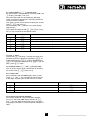
20 kW
160 kW
120
80 kW
120 kW
160 kW
100
IMS (%)
80
60
Par. & (service level 30%) 40
par. * (service level 20/10 sec.)
20
0
0
50
100
150
200
250
300
350
400
50
100
150
200
250
300
350
400
Gas valve
Ignition
LDS (control on air transport,
only active during start)
Fan
IMS-system open/closed
Heat demand
0
time (in sec.)
Fig. 17 Switch sequence diagram at nominal flow
- rematic® 2945 C3 K - An optimising / weather-compensated boiler control for multiple boilers.This compensator can regulate the boiler output against outside weather conditions, and provide time and temperature control over the DHW. The compensator is
mounted in one of the boilers and is interfaced to
communicate with the boiler’s controls via the supplied adapter. On site connection of the supplied outside and common flow sensors complete the installation. Set the x value of the boiler control operation
parameter A to 1.
8.4 Boiler control
The Remeha Gas 210 ECO can be controlled using one
of the following methods:
1. Modulating (two wire control)
To make full use of the boiler’s modulating feature, a
rematic® control has to be connected. This control will
provide optimised time and weather compensation to
achieve maximum efficiency and minimum boiler cycling
whilst maintaining design condition within the building.
This applies to both single and multiple boiler installations (up to a max of 8), under the dictates of an
outside and flow temperature sensor.
Note: Please refer to the relevant control leaflet for
optimising / compensation settings.
37
Remeha
Gas 210 ECO
100
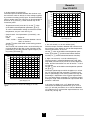
2. Analog control (0-10 Volt DC)
The heat output modulates between the minimum and
the maximum value on the basis of the voltage supplied
by an external analog (0-10V) input. To control the boiler
with an analog signal, the signal has to be connected on
terminals 35 (+) and 36 (-) of the terminal strip in the
instrument panel.
90
desired output (%)
80
- Temperature based (20 to 90 °C) set the x value
of the boiler control operation parameter A to 4.
To set the ratio between voltage and the desired flow
temperature, see par. 6.6.6 and Fig. 18.
70
60
50
40
30
20
10
- Output based - fixed parameters (10 to100%), see
Fig. 19.
0 Volt
= boiler off
1 Volt - 10 Volt = boiler modulates between 10 and
100% on demand.
Set the x value of the boiler control setting parameter A to 5.
The minimal and maximal values are restricted by the
minimal position of the IMS-system (read-out mode,
parameter h) and the maximal adjusted output (setting mode, parameter 6).
0
0
desired flow temperature (°C)
60
50
40
30
20
10
0
4
5
6
7
8
9
5
6
7
8
9
10
4. High / low control (2 x no volt switched pairs)
The heat output is controlled between part load (50%,
adjustable) and full load, by means of a two-stage controller, terminal connections 45 and 46 low fire - 43 and
44 high fire.
Set the x value of the boiler control operation parameter A to 2.
The output percentage on which the boiler runs on low
fire, can be adjusted with parameter 4 (low fire start
point as percentage) in the setting mode. The ‘high fire’
percentage is dependent of the maximal adjusted output, see setting mode, parameter 6 (maximum output).
During this ‘high’ state modulation on adjusted flow temperature is released.
70
3
4
3. On / off control (1 x no volt switched pair)
The heat output modulates between the minimum and
the maximum value based on the set flow temperature,
terminal connections 45 and 46.
Set the x value of the boiler control operation parameter A to either 3 (on/off control without booster
function) or 1 (on/off control with booster function).
80
2
3
Fig. 19 Output control via analog (0-10 Volt) signal
90
1
2
input voltage (V) - DC
100
0
1
10
input voltage (V) - DC
In all cases the boiler uses a ∆T dependant output
control with the following characteristic: up to a ∆T of
25ºC (∆T full load) the boiler runs at full load. Between
∆T full load and ∆T part load the output decreases via a
lineair line (see Fig. 20).
Fig. 18 Temperature control via analog (0-10 Volt)
signal
38
8.5 Safety interlocks
120
8.5.1 Shut-down interlock
As standard the boiler is supplied with a shut down
interlock carrying a 24 Volt AC boiler control circuit.
Any external devices required to stop the boiler (e.g.
limit switches of throttling valves, minimum gas pressure
switches) should be wired in series and connected to
terminals 39 and 40, breaking the circuit will activate
the safety interlock and put the boiler into a shut-off
condition with code b **. If this input is being used,
the wire bridge must first be removed.
100
output (%)
80
60
40
20
8.5.2 Lock-out interlock
As standard the boiler is supplied with a lock out interlock carrying a 24 Volt AC boiler control circuit.
Any external devices required to stop the boiler (e.g.
maximum gas pressure switch) should be wired in series
and connected to terminals 18 and 19, breaking the
circuit will activate the safety interlock and put the boiler
into a lock out condition, code 11 requiring manual
intervention to re-set it. If this input is being used, the
wire bridge must first be removed.
0
0
10
20
30
40
50
60
70
delta T (°C)
Fig. 20 Characteristic output control
8.6 Remaining outputs
8.6.1 Analog output
Dependent on the adjustments of the options/
accessories (see par. 6.6.13) the analog signal can send
out the following values:
Output signal (Volt)
Description
0 - 0,5
Boiler off
0,5
Alarm signal
0,5 - 1,0
Boiler off, pump on
1,0 -10
Boiler output from 10 to 100% or
Flow temperature from 10 to
100°C
Table 21
Analog output signal
This output is on terminals 33 (-) and 34 (+).
39
Remeha
Gas 210 ECO
8.7 Options/accessories
8.6.2 Indicating module No.1
With this standard module (AM3-2 print) it is possible to
report / control the following:
- Common alarm (lock-out): the internal Volt free contact across terminals 49 and 50 (n/o) will change to
n/c when the boiler goes to a lock-out condition.
- Boiler shut-off mode: the internal Volt free contact
across terminals 51 and 52 (n/o) will change to n/c
when the boiler goes to a shut-down condition.
Note: boiler shut-off mode is a normal operating condition (see shut-off mode codes, par. 6.4).
8.7.1 Provision for thermostat pocket
The flow pipe is tapped and standard plugged (½” BSP
‘f’). This can be used to insert an optional thermostat
pocket (length 35 mm, ½” BSP ‘m’) for use with external
sequence control.
8.7.2 Water pressure sensor
The water pressure sensor shuts the boiler down if the
system pressure drops below sensor set point (basic
setting 0.8 bar). The sensor is provided complete with
wiring and connecting plug which is connected to a
mating plug in boiler wiring. See fitting instructions provided with the sensor.
Note: by pressing the s- and e-keys simultaneously
during 2 seconds the presence of the sensor is being
detected and will monitor system pressure in accordance with set point.
Maximum power supply
: 230 Volt.
Maximum current per contact : 1 A.
- External gas valve control: on heat demand, a 24 Volt
signal is provided across terminals 22 and 23, this
power supply can be used to open an external gas
valve or indicate to a BMS system that the control
voltage is OK. The 24 Volt signal is lost immediately
when the boiler combi-block shuts.
8.7.3 Differential pressure sensor
This differential pressure sensor is fitted to the boiler
monitoring the differential pressure between the burner
inlet and heat exchanger outlet. Should the differential
pressure exceeds XX mbar the LED on the instrument
panel above the e-key will flash red on and off. The
boiler will continue to function normally, but service visit
must be arranged. The sensor is provided complete with
sensing tubes, wiring and connecting plug which is connected to a mating plug in boiler wiring. See fitting
instructions provided with the sensor.
Note: by pressing the s- and e-keys simultaneously
during 2 seconds the presence of the sensor is being
detected and will monitor differential pressure.
Power supply
: 24 Volt AC.
Maximum current : 1 A.
8.7.4 Gas valve proving (only for 120 and 160 kW
boilers)
The boiler gas combi-block has two safety shut-off valves. A valve proving system can be installed on the combi-block monitoring the gas pressure between the two
valves during the pre-purge time of the boiler (once fitted the pre-purge time is extended to allow VPS-system
to function). Should the sensor detect a pressure loss
during this period, the boiler will go to a lock-out condition displaying fault code 89.
Connecting the gas valve proving is described in the
fitting instruction which is supplied with it. The presence
of the gas valve proving can be adjusted by means of
digit J in the setting mode on service level (see par.
6.6.13.)
Fig. 21 Indicating module No.1
(0021H7900010)
40
8.7.5 Minimum gas pressure switch
A minimum gas pressure switch can be connected to
terminals 41 and 42. Note that the wire bridge must
first be removed. The gas pressure switch will shut the
boiler down (with shut-off code b @^) or prevent it
operating if the gas pressure drops below 17 mbars.
The boiler doesn’t lock-out, but waits until pressure is
re-established above minimum level.
8.8 Remaining connections
8.8.1 System pump
It is possible to connect a system pump to terminals 14
and 15 with the following restrictions.
Maximum power supply : 230 Volt
Maximum current
: 1 A.
The connections are polarity sensitive, terminal 15 is
live.
8.7.6 Indicating module No.2
With this optional module (AM3-10 print) it is possible
to report the boiler operating mode ‘boiler on’ and ‘boiler
high fire’.
The internal Volt free contact across terminals 53 and 54
(n/o) will change to n/c when the boiler starts.
The internal Volt free contact across terminals 55 and
56 (n/o) will change to n/c when the boiler goes to high
fire (confirmation of high fire will depend on parameter
% setting).
If system pump exceeds these values the terminals can
only be used to switch a pump relay.
8.8.2 Frost protection
Install the boiler in a frost-free room. If the boiler water
temperature drops below 7°C, the built-in frost protection
sytem is activated as follows:
- below 7°C - system pump is switched on if
connected to boiler
- below 3°C - boiler is switched on.
When the flow temperature reaches 10°C the boiler and
pump switch off (note: pump signal has fixed run on time
of 15 minutes).
Maximum power supply
: 230 Volt;
Maximum current per contact : 1 A.
Note: This control is designed to protect the boiler
- for full system protection use a frost themostat
(across terminals 45 and 46) or a weather compensator.
Fig. 22 Indicating module No.2
(0021H7900009)
41
Remeha
Gas 210 ECO
9
9.1
1.
2.
3.
4.
5.
6.
7.
8.
9.
10.
11.
12.
13.
14.
15.
COMMISSIONING
16a. Check and correct, if necessary, the boiler for correct gas/air setup. Checking takes place on full and
part load, adjustment takes place only on full load.
For checking and adjusting are required: an electronical CO2-gauge (on the basis of O2) (measuring
point 3, see Fig. 02) and a gas pressure gauge.
Note that the opening around the measuring probe is
sealed properly during measurement.
Note also that measuring the O2 levels in the flue gas
is necessary, because direct measurement of CO2
can lead to inacuracies due to varying CO2 levels
in the natural gas.
16b. Connect gas pressure gauge to the gas combiblock.
16c. Connect flue gas analyser, ensuring the connections are gas tight.
16d. Operate boiler at full load (forced mode ‘high’) by
pressing the m- and [+]-key simultaneously for 2
seconds. The letter h will now appear on the
display.
16e. When full load is reached, check gas pressure
(with removed front casing) against Table. 22. The
pressure has to be 0 mbar. Adjust if necessary
using the adjustment screw on the gas combiblock.
Re-adjustment takes place with the zero point adjustment of the gas combi-block (see Fig. 23).
Initial lighting
Isolate main power supply.
Remove the front casing.
Check gas supply is available, sound and vented.
Open instrument panel.
Check the electrical connections match the control
options.
Check boiler and installation is full of water and if
pressurised at the correct pressure.
Vent the system.
Fill the siphon with water.
Close instrument panel.
Check the flue gas and air inlet ducting or
combustion air supply.
Open the gas cock.
Re-establish power supply to boiler and controls.
Set the boiler control to heat demand or use
manual override.
Switch the boiler on 1.
The boiler should start with the run sequence
indicated in the code-display:
0 = IMS-system moving to maximum.
5 = Waiting mode; the fan runs and the boiler
waits until sufficient air transport is established (air pressure switch open or closed).
1 = Pre-purging.
2 = Ignition of the gas/air mixture.
3 = The burner is firing.
front casing removed
front casing placed
CO2% in …
CO2%
Full load (100%)
8.7 ± 0.2% 5.4 ± 0.4% 0 mbar
9.0 ± 0.2% 4.8 ± 0.4% not measurable
Part load (±10%)
8.7 ± 0.5% 5.4 ± 0.9% not relevant
9.0 ± 0.5% 4.8 ± 0.9% not measurable
Table 22
O2%
gas pressure gas CO2%
valve
O2%
gas pressure gas
valve
Adjustment values CO2 and O2
Gas multi bloc, 3 sections
Gas multi bloc, 4/5 sections
Fig. 23 Zero point adjustment gas combi-block
(0021H7900004)
42
16f. Check CO2-percentage (O2-percentage) against the
table. Adjust if necessary using the adjustment
screw on the IMS-system (see Fig. 24). Is the CO2percentage too high (O2-percentage too low), turn
the adjustment screw to the right, simultaneously
holding the nut with a ringwrench. Is the CO2-percentage too low (O2-percentage too high), turn the
screw to the left.
Check the flame via the inspection window. The
flame should be stable, mainly blue with burner
surface covered by orange dots.
Note:
The Remeha Gas 210 ECO is supplied with a number of
factory default settings which should be correct for most
installations. If other setting values are required: see par.
6.5 and 6.6.
The following operating situations are now possible:
23a. Modulating operation: The output of the boiler
modulates on the basis of the flow temperature,
asked by the modulating control (see also note
under point 23c and par. 8.4).
23b. High/low operation: The boiler is operating at part
load or full load, depending on the heat demand
(see par. 8.4). On the safety boundaries the boiler
is going to modulate.
23c. On/off operation: The boiler modulates between
minimal and maximal output on the basis of the
flow temperature pre-set on the boiler (see also par.
8.4).
Note: The boiler will first burn at forced part load.
The factory setting for forced part load time is
2 minutes. This setting is correct if use is made
of modulating controls (see point 22a). For on/off
operation a forced part load time of 3 minutes is
recommended (setting mode, parameter *, see
par. 6.6.4).
23d. 0-10 Volt operation: Depending on the adjustments
(see par. 8.4), two situations are possible:
- The given off output varies lineair with the sent
signal, 1V = 10%, 10V = 100%.
- The given off flow temperature varies lineair with
the sent signal, 1V = 10°C, 10V = 100°C.
The boiler modulates on the basis of the adjusted
flow temperature (setting range 20°C up to 90°C)
and on a maximal ∆T protection.
Fig. 24 Adjustment point CO2% / O2% IMS-system
9.2 Shut-down
1. Switch off the on/off switch of the boiler. With this, a
possible boiler control will be without tension also.
2. Close the gas cock.
(0021H7900018)
16g. Run the boiler at part-load by pressing the m- and
[-]-key simultaneously for 2 seconds. The letter l
will now appear on the display.
16h. When part load is reached, check CO2-percentage
(O2-percentage) against Table. 22. Should the value
lie outside the boundaries as mentioned in the
table, please contact our Service Department.
16i. Remove the flue gas analyser. Seal the test point.
17. Fit the boiler front panel.
18. Allow boiler to run up to its set flow temperature
and shut off.
19. When pumps have stopped, vent the system and
check the water pressure.
20. The boiler is now ready for use.
21. Set system controls to the required values.
22. Send the commissioning reports to Broag.
Note:
When the boiler is out of operation, it is not protected
against frost!
43
Remeha
Gas 210 ECO
10
FAULT-FINDING
10.1 General
In case of a failure, both digit in code-display as digits
in t-display will flash. For an explanation of the various
failure codes and their possible causes, see Table. 23
in par. 10.2.
10.2 Overview malfunctions (locking)
On failure codes as mentioned below, pay attention to
possible dots between the digits ()0 = 100, )1 =
101 and )2 = 102, see also par. 6.1.5).
Notes:
- For a read out of the most recent faults, see par. 6.8.
- Besides failure codes (lock-outs) also shut-off codes
exists (see par. 6.4). During this condition the codedisplay will show a b, whilst the t-display indicates
the cause with two flashing dots. A shut-off code may
indicate a system problem or an incorrect parameter
setting and does not represent a boiler failure.
Important:
Before resetting, accurately record the fault code (3
digits, blinking and dots included) and always pass on
this information if you request assistance. The fault code
is important for correctly and rapidly tracing the nature
of the fault.
First of all check if it’s a failure message by verifying the
following points:
- Check if the power supply is present.
- Check if heat demand is present and the boiler control
is adjusted properly.
If the above-mentioned points are OK and still the boiler
isn’t running, then it concerns a failure message.
44
Failure
code
00
Description
Cause / control points
Flame simulation
- Burner still glows after a too high CO2-percentage.
- Check combined ignition/ionisation probe (distance between pens 3 - 4
mm).
- Gas combi-block leaks or stays in opened position.
01
Short circuit in 24V circuit
Check:
- wiring to the sensors
- wiring to the gas combi-block.
02
No flame or no ionisation
(after 5 start attempts)
a. No ignition spark. Check:
- connection of ignition cable and spark plug cap
- ignition cable and electrode for breakdown
- on breakdown between spark plug cap and earth wire/mass
- electrode distance: must be 3-4 mm
- condition of the burner deck (short circuit burner deck/electrode)
- earth connection/mass.
b. Ignition spark, but no flame. Check if:
- gas cock is open
- inlet gas pressure is sufficient (20 - 30 mbar)
- gas pipe is vented properly
- gas valve is energized during ignition and if it opens too
- electrode is clean and fitted properly
- the gas pipe is not clogged or shows an assembly fault
- the air supply or flue gas outlet is not clogged or shows an assembly
fault
- the gas/air ratio is adjusted properly.
c. Flame, but ionisation signal not sufficient (< 3 A
- ). Check:
- condition of electrode and earth wire/mass
- the temperature sensors on leak current.
03
Gas valve defective
The automat ‘sees’ no gas combi-block.
Check if:
- the wiring on the gas combi-block is connected properly
- the gas combi-block is defective (burned / short circuit).
04
Control fault
Voltage interruption during lock-out condition.
05
External influences
Remove possible external EMC-influences.
08
Air pressure differential
switch does not close.
Check:
- the air supply or flue gas outlet is not clogged or shows an assembly
fault
- the air pressure differential switch and the connections.
45
Remeha
Gas 210 ECO
Failure
code
11
Description
Cause / control points
Disturbance internal
communication bus
- Check flat cable in the instrument panel on short circuit
- Liquid formation on display
- Remove possible external EMC-influences.
12
External interlock
- External interlock, connected to terminals 18 and 19 of the terminal
strip, became effective or wire bridge is removed
- Fuse F2 from the automat is defective.
18
Flow temperature too high
Check:
- water flow
19
Return temperature too high - whether the installation is vented properly
- the temperature sensors on deviations
- the water pressure in the system.
28
Fan does not run
- Fuse F4 defective
- Fan or rotor defective or improperly fitted
- Fan cable or connector is corroded. Result: power supply or PWMsignal is absent.
29
Fan keeps running or signal
not correct
- Check connectors of fan cable on both fan as automat side
- Fan defective
- Extreme draft through flue gas discharge duct.
30
Max. ∆T exceeded
Check water flow.
31
Temperature sensor fault
Short circuit in flow temperature sensor.
32
Temperature sensor fault
Short circuit in return temperature sensor.
35
Temperature sensor fault
Short circuit in flue gas temperature sensor.
36
Temperature sensor fault
Flow temperature sensor defective or not connected.
37
Temperature sensor fault
Return temperature sensor defective or not connected.
40
Temperature sensor fault
Flue gas temperature sensor defective or not connected.
52
Maximum flue gas
temperature exceeded
Check heat excanger on fouling on flue gas side.
61
Air transport
Air pressure differential switch does not open. Check if:
- air pressure differential switch is defective
- there is short circuit in wiring
- there is extreme draft through flue gas discharge duct.
77
83
Ionisation signal lost during
operation (after 4 restarts
within one heat demand
cycle)
- Flue gas recirculation. Check flue gas discharge duct on possible
assembly faults and the heat excanger on possible leaks
- Insufficient air transport due to clogging
- Check adjustments of the boiler.
Heat exchanger temperature Check if:
too high
- circulation pump runs
- water flow through the boiler is sufficient
- water pressure > 0,8 bar.
46
Failure
code
86
Description
Cause / control points
Close (0%) and end position Check:
(100%) IMS detected
- adjustment of the 0% and 100% pennant of the IMS (both in light
simultaneously
sluice?)
- wiring and connectors.
If OK, replace print on the IMS.
87
Close (0%) position IMS not
detected
Check:
- light cell on fouling
- adjustment of the 0% pennant of the IMS
- wiring and connectors.
If OK, replace print on the IMS.
89
Gas leak detected
The gas valve proving system (VPS) has detected a gas leak. Check for
external leaks. If OK, replace gas combi-block.
93
Close (0%) position and
minimum position IMS
detected simultaneously
Check:
- adjustment of the 0% and minimum pennant of the IMS (both in light
sluice?)
- wiring and connectors.
If OK, replace print on the IMS.
95
Temperature sensor fault
Short circuit in heat exchanger temperature sensor.
96
Temperature sensor fault
Heat exchanger temperature sensor defective or not connected.
)0
Minimum position IMS lies
above start position IMS
Check:
- adjustment of the minimum pennant of the IMS
- wiring and connectors.
If OK, replace print on the IMS.
)1
Minimum position IMS not
detected
Check:
- light cell on fouling
- adjustment of the minimum pennant of the IMS
- wiring and connectors.
If OK, replace print on the IMS.
)2
End position (100%) IMS not Check:
detected
- light cell on fouling
- adjustment of the 100% pennant of the IMS
- wiring and connectors.
If OK, replace print on the IMS.
Other
codes
Automat failure
With not mentioned codes in this table, proceed as follows:
- press once at reset-key
- check wiring on possible short circuit
- when the same failure code keeps occuring, please contact our Service
Department.
Table 23
Fault codes
47
Remeha
Gas 210 ECO
11
INSPECTION AND SERVICING / MAINTENANCE INSTRUCTIONS
11.1 General
The Remeha Gas 210 ECO has been designed to need
minimum maintenance, but to ensure optimum efficiency
we advise that once a year the boiler should be checked
and if necessary cleaned and reset.
All service and maintenance must be carried out by a
qualified Engineer with the relevant training and certification (i.e. CORGI - ACOPS - etc.).
11.2.4 Check the adjustment of the ignition probe
Check the adjustment of the ignition probe (distance
between pens 3 - 4 mm) and when necessary, renew the
probe (including gasket).
11.2.5 Check the water pressure
The water pressure must be at least 0.8 bar. The water
pressure is dependent on the height of the central heating installation above the boiler (statical pressure, 1 bar
= 10 metres height). Recommended is to fill the installation up to circa 0.8 bar above this statical pressure.
11.2 Annual inspection
The annual inspection of the Remeha Gas 210 ECO can
be limited to:
- check combustion characteristics
- cleaning the IMS-system
- cleaning the siphon
- check the adjustment of the ignition electrode
- check for leaks (water side, flue gas side and gas
side/soundness)
- check system pressure
- check control settings.
11.3 Maintenance
If during the annual inspection result indicate that either
combustion or heat exchanger are no longer at the
optimum level, additional maintenance should be carried
out as follows:
- cleaning the IMS-system
- cleaning the fan
- cleaning the heat exchanger with compressed air and
possibly rinsing with water
- clean the burner assembly (using compressed air
only)
- cleaning the siphon.
11.2.1 Check combustion characteristics
This can be done by measuring the O2/CO2-percentage
in the flue gas discharge pipe (see Fig. 02, position 3)
and the gas pressure on the gas combi-block (see Fig.
02, position 11).
To do this, heat the boiler up to a water temperature
of approximately 70°C. The flue gas temperature can
also be measured on the measuring point in the flue
gas discharge pipe. This flue gas temperature must not
exceed the return temperature with more than 30°C.
When the combustion characteristics appears to be not
optimal any more according to this check, clean according to the indications in par. 11.3. See for adjustments
par. 9.1.
Work order:
1. Remove the front casing.
2. Let the boiler run at maximum power (forced mode
‘high’) by pressing the m and [+]-key simultaneously
during 2 seconds. The letter h will now appear on
the display.
3. If the IMS-system is fully open and the pre-purging
begins, isolate the electrical power supply to the
boiler (on/off switch on instrument panel).
4. Close the valve in the gas supply pipe to the boiler.
11.2.2 Cleaning the IMS-system
- Remove the electrical connections from the IMS.
- Remove the air pressure hose from the IMS.
- Loosen socket-head bolts (6) around the black protection cap of the IMS.
- Take away protection cap of the IMS.
- Lift the metal top including joined axis and dishes
straightly out of the IMS base. Attention: prevent
damaging axis and dishes!
- Clean dishes and adapted contours of the IMS with a
cloth drenched in spirit. Don’t use any sharp objects
to do this and be sure that the small gas dish during
cleaning is not distorted.
- Reassemble all parts in reverse order. Be sure that
with replacing the metal top in the IMS base, the axis
is placed in its support!
Cleaning the IMS-system
5. Remove the electrical connections from the IMS.
6. Remove the air pressure hose from the IMS.
7. Loosen socket-head bolts (6) around the black protection cap of the IMS.
8. Take away protection cap of the IMS.
9. Lift the metal top including joined axis and
dishes straightly out of the IMS base.
Attention: prevent damaging axis and dishes!
10. Clean dishes and adapted contours of the IMS with
a cloth drenched in spirit. Don’t use any sharp
objects to do this and be sure that the small gas
dish during cleaning is not distorted.
11. Reassemble all parts in reverse order. Be sure that
with replacing the metal top in the IMS base, the
axis is placed in its support!
11.2.3 Cleaning the siphon
Remove the siphon from the boiler and clean it.
Fill the siphon with clear water and assemble the siphon.
48
Cleaning the fan
12. Remove the electrical connections from the fan.
13. Unscrew the union nut between the IMS-system and
the gas combi-block.
14. Remove the bolts and nuts on the press side of the
fan.
15. Remove the fan including the IMS-system.
16. To inspect/clean the fan, the IMS-system has to be
removed from the fan.
- To do this, unscrew the bolts on the suction side
of the fan.
- Use a synthetic brush for cleaning.
- Attention: don’t move the balance clips in the
paddle wheel!
- Extract any loose dust particles from the fan
before reassembling. Be sure the sealing plate
between fan and mixing curve is positioned
correctly.
Cleaning the heat exchanger
17. Remove the nuts from the heat exchanger inspection hatch on the front of the heat exchanger.
18. Take away the heat exchanger inspection hatch.
19. Cleaning the heat exchanger with compressed air
and possibly rinsing with water.
20. The drain pan can also be cleaned by loosening
the plug on the top of the drain pan (in front of the
flue gas outlet) and subsequently flush the pan with
water.
Cleaning the burner assembly
21. Remove the burner. Check the burner visually and
possibly clean carefully with air (e.g. with compressed air between 2 and 5 bar, distance nozzle burner surface circa 1 cm).
Cleaning the siphon
22. Remove the siphon. Clean siphon, fill with clear
water and reassemble.
Attention
The gasket between heat exchanger inspection
hatch and heat exchanger can stick, just as the gasket between burner and heat exchanger. Be careful
that the gasket won’t tear.
A damaged or harden gasket has to be replaced at
all time through a new gasket.
After this, reassemble all parts again in reverse order.
Be careful that the cables don’t touch any hot boiler
parts!
Restart the boiler.
49
Remeha
Gas 210 ECO
50
ECO
210
Gas
Remeha
Broag Ltd
Head Office
Remeha House,
Molly Millars Lane,
Wokingham,
Berkshire RG41 2QP.
Tel.: 0118 9783434
Fax: 0118 9786977
Email address:
[email protected]
Website: www.broag-remeha.com
Branch Office
Unit 3, Kestrel Close,
Quarry Hill Ind. Estate,
Ilkeston,
Derbyshire DE7 4RD
Tel. 0115 9440778
© Copyright
All technical and technological information contained in these technical instructions, as well as
any drawings and technical descriptions furnisched by us remain our property and may not be
multiplied without our prior consent in writing.
Subject to alterations
55386/00/02.01/P&D
52
Fax 0115 9440588