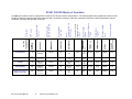
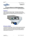
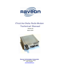
1
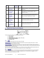
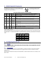
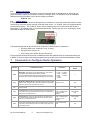
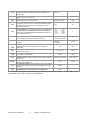
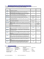
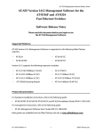
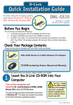
RV-M7 G X
GPS Transponder
Quick-Start Guide
Version C0 February 2010
RV-M7 GX
RV-M7 GX WX
Raveon Technologies Corporation
990 Park Center Drive, Suite C
Vista, CA 92081
www.ravtrack.com
www.raveontech.com
M7 GX Technical Manual
1
Raveon Technologies Corp.
1.
1.1.
Safety / Warning Information
Blasting Caps and Blasting Areas
To avoid possible interference with blasting operations, turn off this radio or remove the DC power when
you are near electrical blasting caps, in a blasting area, or in areas posted: “Turn off two-way radio.”
Obey all signs and instructions.
1.2.
Potentially Explosive Atmospheres
Turn off your radio prior to entering any area with a potentially explosive atmosphere. Do not install this
product for use in areas with potentially explosive atmospheres. Do not remove, install, or charge batteries
in such areas. Sparks in a potentially explosive atmosphere can cause an explosion or fire resulting in bodily
injury or even death.
Note: The areas with potentially explosive atmospheres referred to above include fueling areas such as
below decks on boats, fuel or chemical transfer or storage facilities, areas where the air contains chemicals
or particles, such as grain, dust or metal powders, and any other area where you would normally be advised
to turn off your vehicle engine. Areas with potentially explosive atmospheres are often but not always posted.
Use this manual in conjunction with the M7 GX Technical Manual, which contains
important safety, licensing, and FCC information.
2. Overview
Raveon’s RV-M7 GX series of GPS transponders are a rugged high-speed UHF data modems with a built-in
12-channel GPS receivers. The M7 GX has ½ to 5 watts of RF power output, and operates as both a GPS
transponder for tracking, and a radio modem for sending and receiving data.
The M7 GX may be configured for a number of different GPS applications, including:
Transponder:
Periodically transmit position and status. TX only.
RavTrack PC:
Connect the M7 GX to a personal computer running RavTrack PC (or other PC software) to view a
map showing location, status, log movement, set alerts, and make reports from the data.
Radar Display:
Connect M7 GX to a marine plotter or radar display, and icons will appear on the display showing the
location of all other M7 GX radios in the system.
GPS display:
Connect M7 GX to a hand-held or mobile GPS, and icons will appear on the display showing the
location of all other M7 GX radios in the system.
-LX receive only: This configuration is for the M7 LX model. Is a M7 GX without the internal GPS. It cannot transmit
location, status, or trigger alerts, but it will receive and output the location and status of other M7 GXs
in the system.
For privacy and security, over-the air encryption is standard on every M7 GX radio. For network versatility,
the M7 GX incorporates a 16-bit identification code, allowing up to 65,000 objects to be identified in one
system. For wide-area coverage, all M7 GX transponders may be set to store-and-forward messages from
other M7 GX transponders.
3. Operation
The M7 GX operates in a number of different “GPS Modes”, each mode specific to the application it is being
used in. The mode of operation is set with one simple command, the GPS x command. The different modes
change the operation of the M7 GX in a number of ways. The serial-port data rate is set, the types of NMEA
formatted messages it will send out or accept is set, as will as how the internal UHF radio is used. The table
below summarizes this.
M7 GX Technical Manual
2
Raveon Technologies Corp.
GPS
Mode
GPS 1
GPS 2
Common Usage
Transponder
Simple tracking,
AVL, security.
PC / Base Station
Default
Serial Port
Baudrate
Output
Message
Description
4800
RMC,
GLL
Transmit only in this mode. The receiver is off and GPS is turned
off between transmissions. This is the lowest-power consuming
mode. No RX.
38400
PRAVE
Connect the M7 GX to a PC computer running RavTrack PC (or a
custom application), The PRAVE message is in NMEA format,
and provides location and status information for every
transponder it receives.
Proprietary interface
for PC applications
that monitor M7
Transponders.
GPS 3
Marine Radar
Displaying the
location of M7
transponders on a
ship RADAR
screen.
38400
TLL
Connect the M7 GX to a marine RADAR display or plotter with a
serial port, and waypoints will appear on the GPS screen at the
location of all M7 GX transponders within radio range. The
display must support the NMEA 0183 TLL message.
GPS 4
GPS Display
Lowrance and
Garmin GPS
displays. Mobile
displays.
4800
WPL
Connect the M7 GX to a mobile or hand-held GPS with a serial
port, and waypoints will appear on the GPS screen at the location
of all M7 GX transponders within radio range.
GPS 5
-LX No GPS
module
38400
PRAVE
Connect the M7 GX to a PC running RavTrack PC, or change the
message to WPL and use with a GPS display. No internal GPS,
so no positions/status transmissions.
Lowrance and Garmin
GPS displays. Radar
displays. Mobile
displays.
4. Electrical Inputs and Outputs
The front panel of the M7 GX modem has these features:
1.
2.
3.
4.
5.
RF connector
Power LED
Status LED (Receive data = green, TX = red)
9-Pin Serial I/O connector
DC Power Jack
4.1.
LEDs
The status LED visually show the current status of the radio.
Status LED (TX) This LED blinks red when the transmitter keys and is putting out RF power. It blinks
green upon the reception of data or RF carrier.
Power LED (PWR) This LED does a short blink, once every two seconds, indicating to the user that the
power to the modem is ON and the modem is working. When the modem is in the command mode, this LED
will blink on and off, once per second.
When the GPS is trying to acquire satellite lock, the Status and Power LEDs will alternately blink back and
forth. This usually takes 10-20 seconds upon power-up or loss of satellite signal.
4.2.
DC Power
DC power for the modem is connected to the 2-pin DC power input jack labeled DC IN. Use the supplied
cable to connect the DC power. The red wire is positive (+) and the black wire is negative. Raveon
recommends at least 18 AWG wire be used.
M7 GX Technical Manual
3
Raveon Technologies Corp.
5. RS232 Serial I/O Connector
The RS232 9-pin serial I/O connector is a female 9-pin Dthe following pins configuration. It is pinned out so that it
computer or PC’s 9-pin COM port.
subminiature connector having
may be plugged directly into a
Front-view of DB-9 connector on modem (female)
Pin
1
Name
CD
Dir
out
2
3
RxD
TxD
out
in
4
DTR
in
5
GND
6
DSR
7
RTS
8
CTS
9
Power
out
in
out
Function
Carrier
detect
Receive data
Transmit
data or IN2
Level / Specification
Indicates presence of carrier. Logical 0 means carrier is present. If disabled, it is
asserted (0). It will be a 1 when the modem is in the configuration mode.
Data out of the modem.
Data into the modem.
Also used as digital input IN2 for exception reporting. GND or floating for a 0, >3V for
digital 1.
Used as digital input IN0 for exception reporting. GND or floating for a 0, >3V for digital
1. Use the TRIGBITS command to set which bits are used as inputs.
Signal and power ground
Data terminal
ready or IN0
Ground
connection
Data Set
Ready
Request to
send
or
IN1
Normally is set to 0 when modem is powered on and running. Modem sets to a 1 when
in low-power mode.
Used to stop/start the flow of data out TxD pin. 0 = OK, 1 = don’t send.
Also used as digital input IN1 for exception reporting. GND or floating for a 0, >3V for
digital 1.
Used to stop the flow of data going into the RxD pin from the device connected to the
M7. 0 = OK to send, 1 = don’t send
User may supply the DC power to the modem on this pin. If the DC input connector is
used to power the radio, then the DC power will also be on this pin.
Clear to send
In or
out
DC power
Note: RS-232 signals use positive and negative voltages to represent digital 1s and 0s. A positive voltage is a 0, and a
negative voltage is a digital 1.
This pin-out allows it to be directly plugged into a computer’s 9-pin serial port using a conventional 9-pin RS232 serial cable. To connect it to a modem, or peripheral that has a serial port, you will need a “null-modem”
cable.
IN 2
(TXD)
0
0
0
0
1
1
1
1
IN 1
(RTS)
0
0
1
1
0
0
1
1
IN 0
(DTR)
0
1
0
1
0
1
0
1
Hexadecimal
Representation
0
1
2
3
4
5
6
7
6. Configuring the M7 GX
6.1.
Overview
There is a “Command Mode” used to program and configure the M7 GX. In the Command Mode, the M7 GX
modem accepts commands via the serial port and the user may configure the internal parameters of the unit,
such as frequency and ID codes.
6.2.
Command Mode
The M7 GX modem may be put into a “Command Mode”, by entering a sequence of three plus characters
(+++). Using serial communications software such as HypterTerminal, send the 3-character command
sequence “+++”.
When the M7 GX modem first enters the Command Mode, it sends its model number out its serial port, and
then an “OK”.
M7 GX Technical Manual
4
Raveon Technologies Corp.
6.3.
Setting a Parameter
To set a parameter in the M7 GX modem, enter the Command Mode as described above, then enter the
proper command, a space, the parameter, and then a carriage return. For Example, to set the destination
address of the M7 GX modem to 25, enter the following command:
ATDT 25 <CR>.
6.4.
CONFIG Button
If certain parameters within the M7 GX transponder are modified in a manor that causes the modem to cease
functioning or if the user cannot enter the command mode via the “+++” method, there is a small push-button
inside the M7 to assist. This “CONFIG” button may be pressed at any time, and forces the M7 GX into a
known state. The CONFIG button is located inside the M7 GX. Remove the rear cover, exposing the circuit
board and he button as shown below.
The default settings that the M7 GX will revert to when the CONFIG button is pressed are:
1. Serial port 9600 baud, 8 data bits 1 stop, no parity
2. Serial port flow control is off.
3. ATCT setting set to 60000 (60 second time-out)
Even though the serial baud rate reverts to 9600 baud when the CONFIG button is pressed and the IO port
is RS232, it will revert back to the settings programmed into the M7 GX once the Command Mode is exited.
7.
Commands to Configure Radio Operation
Command
Command Description
ATBD
Baud Rate – Sets serial com port baud rate (bps). Over-the-air
(throughput) baud rate is set with ATR2 command.
If a PC’s serial baud rate is set higher than the fixed over-the-air
baud rate of the module, hardware handshaking may be required.
Range: 0 – 7
0 = 1200 5= 38400
1 = 2400 6=57600
2 = 4800 7=115200
3 = 9600
4 = 19200
ATDT
Destination Address to call– Sets address of the modem to send
data to. Note, this parameter is entered in HEX format. Each digit
may be a 0,1,2,3,4,5,6,7,8,9,A,B,C,D,E,or an F.
Range: 0-FFFF
ATF
Display frequencies – Display all of the frequencies programmed into all of the
channel memories.
ATFT
Transmit Frequency – Program the transmit frequency for this channel. Enter in
Hz or in MHz. The frequency will automatically be saved in non-volatile memory
(flash) for this current channel number.
ATFR
Receive Frequency – Program the receive frequency for this channel. Enter in
Hz or MHz. The frequency will automatically be saved in non-volatile memory
(flash) for this current channel number.
ATFX
TX and RX Frequency – Program the receive and transmit frequency for this
channel. Enter in Hz or MHz. Same as issuing an ATFR and an ATFT command.
The frequency will automatically be saved in non-volatile memory (flash) for this
current channel number.
M7 GX Technical Manual
5
Raveon Technologies Corp.
Parameters
Factory
Default
3
1234
N/A
Range: See product data
sheet. For MURS products,
frequency cannot be
changed.
Range: See product data
sheet. For MURS products,
frequency cannot be
changed.
Range: See product data
sheet.
See product data
sheet.
See product data
sheet.
N/A
ATHP
Channel Number – Select separate channels to minimize
interference between multiple sets of modules operating in the
same vicinity.
Range: 1 - 6
ATMK
Address Mask – Configures local and global address space. Each
digit may be a 0,1,2,3,4,5,6,7,8,9.
Range: 0000 - FFFF
FFFF
Range: 0000 - FFFF
1234
ATMY
ATPO
Unit Address – Configures the individual; address for this unit.
Each digit may be a 0,1,2,3,4,5,6,7,8,9.
RF Power Output. Set or show the RF power output setting. Value
is in percent, from 0% to 100%. Use and RF wattmeter to confirm
the power setting, and adjust the % accordingly to obtain the
desired RF power level.
1
0-100
100
Over-The-Air bit rate - This is the data rate the radio uses to send data over the
air. All RF modems in the network must use the same over-the-air baud
rate. Refer to section Error! Reference source not found. for information on
how to set the OTA baud rate.
Range:
0 = 800
5 = 9600 2L
1 = 1200
6 = 19200 4L
2 = 2400
ATRV
Disable Remote Access – When enabled (set to a 0), the modem will respond
to over-the-air RPR requests, Pings, and over-the-air commands.
0 = Remote Access on
1 = Remote Access disabled
ATSL
Serial Number – Reads and returns a unique serial number for
thjs unit.
Read Only
ATR2
ATSH
or
SHOW
Show – Display the configuration of the modem. This will return a
page of ASCII characters, showing the main configuration
parameters.
ATST
Statistics – Show the unit’s operational statistics. See Statistics
section of user manual.
ATVB
ATVR
REPEAT n
PING
SHOW
7 = 5142 2L
3 = 4800
8 = 9600 4L
4 = 8000 4L
9 = 2000 2L
1 - 999999999
3
1
unique
none
None
0, 1,2, 3, 4, or 5
None
Read DC input Voltage– Returns the DC input voltage reading, in
mV (12500 = 12.5VDC input).
None
none
Firmware Version – Returns firmware version currently loaded on
the module.
Read Only, 3 characters
Current version
0 or 1
0 (Off)
XXXX
-
None
-
Enable/Disable Store and Forward Repeating – 0=disabled, 1 –
enabled (repeat everything)
Ping another modem. Format is PING xxxx, where xxxx is the ID
of the modem to ping. If remote access is enabled on xxxx, it will
respond.
Show/display an overview of the radio’s configuration.
** indicates values that are calibrated in the factory and are unit-specific. If the “Radio Type”
is changed, these will need to be re-calibrated.
M7 GX Technical Manual
6
Raveon Technologies Corp.
7.1.
GPS Additional Commands to Configure GPS and Tracking Features
The following commands are unique to the –GX version of the M7. When you execute any of these
commands, the new parameter is automatically stored in EEPROM.
Command Description
Command
GX
GPS
Display GPS settings. Show an overview of the current GPS features and
configurations in the M7 GX.
GPS Operation Mode. Read/Set the GX version’s Operating mode.
Parameters
Default
-
-
0-6
1
-
-
0-9999
seconds
10
Reset all GPS (-GX version) parameters. Set the GX version’s Operating
mode to GPS mode 4, and sets all GPS parameters to factory defaults. It
does not erase frequency or other radio-related parameters.
IDLE TX Interval. Set the number of seconds between position transmissions
when the unit is idle (has not moved more than TRIGDX meters).
Privacy Security Key Code. Set the privacy key for this device. It must be
the same key as used on all other Raveon products in your system. It
secures radio transmissions from unauthorized reception. Set it to 0 to disable
security encryption of data.
ID Prefix. Set an ID prefix. The prefix is 1-8 characters that will be put in
front of the ID when reporting an ID as a waypoint name. A dash means no
prefix. Default is a capitol letter V.
2-16 ASCII
characters.
“RAVEON”
1-8 ASCII characters
Set it to “0” for no
prefix.
V
SLOTTIME
TDMA Slot duration. Configure the width of a TDMA slot. 50mS increments.
50 - 1000
200
SLOTNUM
TDMA Slot Number. Configure the slot number that this radio will use to send
its data in.
1-9999
The MYID of
the unit
0-FF
0
1-3599
10
0-FF
0
Active high
0-FF
0
0-999
0
0-999
0
1 - 9999
10
GPS&F
IDLERATE
KEYPHRASE
PREFIX
TRIGBITS
TDMATIME
TRIGPOL
TRIGEX
TRIGDX
TRIGSPEED
TXRATE
I/O Change Reporting. Which bits are used as transmission triggers. This is
a HEX number. Bit 0 is IN0, bit 1 is IN1….
Set/read TDMA Frame time. The length of one TDMA time frame, in
seconds. M7’s may transmit once per frame, and only in their preset timeslot.
Polarity of the input bits. 0 = normal active high operation(causes unit to
transmit when it goes high), 1 = Inverted, active low. This is a HEX number.
Bit 0 is IN0, bit 1 is IN1….
Report on change. Sets which input bits cause a report on change. If a
particular bit is a 1, then it will trigger a report when it changes. The input bit
must also be enable with the TRIGBITS. This is a HEX number. Bit 0 is IN0,
bit 1 is IN1…
Distance trigger. Set a distance (in meters) threshold beyond-which the unit
will transmit its position and status. If set to 0, the unit always reports at the
TXRATE. If set to an distance greater than zero, then the unit reports at the
TXRATE intervals if it has moved this distance since the last report. If it has
not moved, it will still report its position, but at the rate set by IDLERATE. If
IDLERATE is set t 0, then the unit will not report its position when not moving.
Speeding Report. Set a speed (in kilometers/hour) threshold above-which
the unit will begin reporting its position and status. Set to 0 to disable this
feature.
GPS Report Rate. Set number of seconds between GPS reports. This is
also the rate at which the internal GPS will measure position, speed, etc.
Even if the unit is not moving, the GPS periodically measures position and
speed to determine if it has triggered a speed or position transmission.
7.2.
Factory Default Settings
For the UHF M7 GX model RV-M7-UC-GX, the factory defaults GPS settings are:
Radio channel 1 .................464.500 MHz
GPS Mode ............................4 (GPS display)
Over-the-air baud rate:..........4800 baud, 2-level
Serial port.............................. 4800 N/8/1
Hardware flow control ...........Off
RF Power Output ..................5 watts
Channel number ...................1
M7 GX Technical Manual
7
Slot Number............................The same ID
ID Prefix ..................................V
I/O Change reporting ..............0, off
Proximity Alert.........................0, off
Security KEY...........................RAVEON
Position report interval ...........10 seconds
Raveon Technologies Corp.
8. Setup and Initial Configuration
1.
2.
3.
4.
5.
6.
7.
8.
9.
10.
11.
12.
13.
14.
Connect a DC power source to the DC IN connection on the front of the modem.
Connect a good quality antenna, cut to the operating frequency, to the BNC connector on the front of
the modem.
Connect a computer terminal, or PC computer running HyperTerminal, to the 9-pin I/O connector. The
factory default serial ports settings are 4800 bps, 8 data bits, 1 stop, no parity.
Put the M7 GX into the command mode. (enter +++ per Section 0)
Program the GPS mode. See the table on Page 4 to identify the mode to use, and set it with the GPS x
command. Type GX and press enter to see an overview of the current GPS related features and
configuration. For in-vehicle transponders that do not connect to PCs or displays, it is usually GPS 1
mode. For M7’s connected to a PC running RavTrack PC software, it is set to GPS 2.
Program the modem’s operating frequency to your desired operating frequency. This is done with the
ATFX xxx.xxxxx command.
Program the ID in the unit. Sequentially number the M7 GX units in your system, starting with 1. Use
the ATMY command to set the ID.
Program the ID to which this unit will send its data to. Typically this is the ID of the “Base” unit.
Program the SLOTNUM. This is the TDMA slot number that this unit will transmit in. By default it is the
same as its ID. Important! All radios in your system must use different SLOTNUM settings.
ATMK
The network address mask. Default is F000. This means this unit will receive all
transmissions from any other unit with an ID beginning with 0 (0001 thru 0999).
KEYPHRASE
Enter a security key code “keyphrase”. Use any word or phrase 1-16 characters
long. It is case-sensitive. DO NOT FORGET WHAT YOU SET IT TO! The KEYPHRASE is the only
parameter that cannot be read out of the M7 GX. It must be the same as the KEYPHRASE
programmed into all the other M7 GX transponders in your system. The factory default KEYPHRASE
is RAVEON, call capitols.
To see an overview of how the modem is configured, use the SHOW command. To see an overview
of how the GPS features are configured, use the GX command.
Verify the SLOTTIME and TDMATIME are set appropriate for your system. Consult the user manual if
you are not sure. The defaults are 200mS SLOTTIME and 10 second TDMATIME, which will give you
50 slots (numbered 0-49) to track 49 transponders.
Once the unit is configured, type EXIT to exit the command mode.
Remember, that from the factory, all M7 GX GPS transponders are configured to simply work. Plug in power
and they will lock onto the GPS satellite signal and begin transmitting their positions and status in their
appropriate time slot.
8.1.
Enabling Repeater Features
Refer to the technical manual for advanced repeater configuration instructions. To quickly enable repeating
of all data sent from/to units 1-999, use the REPEAT 1 command. This will enable the repeater function, and
configure it to repeat messages, position, and status transmissions.
8.2. Set the Transmission Report rate
Use the TXRATE xx command to set the report rate, in seconds, for the M7 GX transponder. For example,
if you wish the M7 to report every 5 minutes, set the report rate to 300 seconds (TXRATE 300).
If the M7 GX should report position and status when it is moving, set the TXRATE xx to the desired time
between position transmissions. Then, program the IDLERATE xx to the desired number of seconds
between reports when the unit is not moving (idle).
Important!: Set the minimum distance the unit must move for a transmission occur with the TRIGDX xx
command. If TRIGDX is set to zero, then the unit will always report at the interval set with the TXRATE xx
command. This is the factory default setting.
For example, to transmit every 2 minutes when idle, and every 10 seconds when moving more than 500
meters, use these commands:
IDLERATE 120 (to set the idling update interval to 2 minutes.)
M7 GX Technical Manual
8
Raveon Technologies Corp.
TRIGDX 500 (tells it to report at the IDLERATE if it does not move this many meters)
TXRATE 10 (configures it to report every 10 seconds whenever it is moves more than TRIGDX meters)
8.3.
Device Addressing
Security Key
The security KEY programmed into every M7 GX transponder ensures that only M7 GX transponders with
the exact same security code can receive position and status information. The security key is case sensitive,
so “Raveon” and “RAVEON” are two different keys. The factory default is “RAVEON”.
Addressing Basics
Addressing is used to differentiate one M7 Transponder from another. Each must have a unique ID number
programmed into them, so that when a position report is received, the ID of the M7 GX that sent the
message is known. This is called the MYID.
Each M7 GX has an ID programmed into it, and is represented as a 4 digit number. M7 GX IDs may be any
number between 0001 and 9999. The unit’s own ID is programmed with the ATMY xxxx command, and the
ID of the destination modem it sends its messages to (the Destination Address) is configured with the ATDT
xxxx command.
The default Address Mask is F000, which means the M7 GX will receive a transmission from any other M7
as long as the fist digit matches, in this case, is a 0.
For example, to set the MYID of your M7 to 17, enter:
MYID 17 <enter>
To set your M7 to send its position and status data to M7 number 1, enter:
ATDT 1 <enter>
To receive all messages from units with IDs 1-999, and exclude 1000-9999, set the mask to:
ATMK F000 <enter>
8.4.
Time Slots
For optimum efficiency in a M7 GX system, begin sequentially numbering the MYID of the M7 GX
transponders at ID 0001. The second M7 should be ID 0002, and so on.
The M7 GX transponders have internal clocks with 20 ticks-per-second. They can measure time and initiate
transmissions 20 times every second (every 50mS). The factory default allocation is each TDMA time slot is
200mS long, and thus in 10 seconds, up to 49 M7 GX transponders may report position. These parameters
are programmable, and may be re-configured based upon the type of system they are used in. Program the
slot time with the SLOTTIME xxx command, where xxx is in milliseconds.
For over-the-air rates of 4800 baud, Raveon Suggests using a SLOTTIME of 200mS when using a repeater,
or 100mS if there is no repeater in the system.
For over-the-air rates of 9600 baud, Raveon Suggests using a SLOTTIME of 150mS when using a repeater,
or 50mS if there is no repeater in the system.
A TDMA “Frame” time is the time it takes all units in your system to transmit. This is configured with the
TDMATIME xx command. The factory default is 10 seconds, so every 10 seconds, each M7 GX is allocated
a time-slot that it may use to transmit position in. The TDMA frame must be set long enough for all units to
transmit. For example, if you have 199 M7s, and use 200mS TDMA slots, then the TDMATIME should be set
to 40 seconds.
All TDMA frames are synchronized automatically in all M7 GX Transponders to the top of the minute. Slot 0,
frame 0 is at the top of each minute. Slot number 0 is used for future protocol options, and should not be
assigned to any unit.
9. Installation
1.
Secure the M7 modem using the mounting holes on the side flanges of the unit.
2.
Connect a DC power source to the DC IN connection on the front of the modem. Use the supplied
cable, or 18AWG wire, and connect the RED wire to +, and the black wire to – (ground). The black
wire and the case of the M7 should be connected to earth ground.
M7 GX Technical Manual
9
Raveon Technologies Corp.
3.
Connect a good quality antenna, tuned to the operating frequency, to the RF connector on the front
of the modem. Use a quality antenna, and place is at as high-above obstructions as possible.
4.
A separation distance of at least 20 centimeters must be maintained between the transmitter's
radiating structures and the body of the user or nearby persons.
5.
Connect a GPS antenna to the SMA connector of the M7 GX. Although a passive antenna may work
if the cable length is very short, it is recommended that an amplified antenna be used, rated for 3.3V
operation. The GPS antenna must have un-obstructed visibility of the sky.
6.
Connect the computer, terminal, controller, or other hardware device that will be using the M7
modem to its DB-9 serial I/O connector using a shielded cable. Secure it to the M7 with the two
mounting screws on the sides of the DB-9 connector.
7.
If the antenna is mounted out doors, us a lighting arrestor in-line with the antenna, and properly
ground the antenna and the M7 chassis to an earth ground.
8.
Connect Digital Inputs. The stock M7 GX has up to 3 digital inputs, using the input pins of the RS232 serial port. An open circuit or ground is a 0, and if they are connected to a positive voltage
greater than 3V, they are a digital 1.
RS-232 Pin
Function
4 - DTR
7 - RTS
3 - TXD
5 - Ground
Input 0
Input 1
Input 2
GND
10. Operation
Once power is applied to the M7 GX, the internal GPS will begin to try to lock onto the GPS satellites.
The two LEDs on the front of the M7 will begin to alternately blink red back-and-forth every second.
After 10 to 60 seconds, depending upon the satellite strength, the red alternating blinking will stop. This
indicates the internal GPS receiver is locked onto GPS satellite signals, and has a position fix.
The M7 GX will only transmit if it has GPS lock. If the GPS antenna is broke or obscured, the unit will not
report position or status.
When it is locked to GPS, it will transmit its position and status at the interval programmed into the TXRATE
parameter.
Refer to the M7 GX Technical Manual for details on all of the events that will trigger a transmission.
Installation
M7 GX Technical Manual
10
Raveon Technologies Corp.
RV-M7 GX GPS Modes of Operation
$PRAVE
( x=1 )
Yes (1)
3
$GPTLL
( x=2 )
Yes (1)
4
$GPWPL
( x=3 )
No (0)
5
$PRAVE
( x=1 )
No(0)
.
M7 GX Technical Manual
11
Raveon Technologies Corp.
10
10
10
10
Yes
TX & RX
(0)
Yes
TX & RX
(0)
Yes
RX only
(1)
Yes
RX
(1)
No
Can be a repeater
Serial Port Baud
Rate
Digital Input
Triggers
Minimum Distance
Trigger
Speed Trigger
default
Capable of Speed
triggered position
reports
Data
communication via
RS232 also
TX only
(1)
Repeat X
Default = 0(off)
2
DATAMUTE x
TXRATE xx
Position/status
report rate
NMEAOUT x
Output Message
Format
GPS mode
NMEA Position
GGA, GSV, RMC
10
ATBD X
-LX receive only, no
GPS in the unit.
No (0)
TRIGBITS xx
GPS Display
Nothing
TRIGDX xx
Radar
1
TRIGSPEED
xx
RavTrack PC
OUTPUT x
Transponder
GPS x
Command
used to modify
this parameter
Parameter
The GPX x command is used to configure the RV-M7 GX for various common configurations. The following table lists the parameters internal to the
RV-M7 GX that are configured and saved when the GPS x command is executed. After the command is executed, individual parameters may be
modified to customize the operation of the unit.
0
0 (off)
0 (off)
4800
NO
0 (off)
0 (off)
38400
Yes
0 (off)
0 (off)
38400
Yes
0 (off)
0 (off)
4800
Yes
N/A
N/A
38400
Yes
(off)
0
(off)
0
(off)
0
(off)
*
N/A
1
For Technical Assistance email or call Raveon at:
Raveon Technologies Corporation
990 Park Center Drive, Suite C
Vista, CA 92081
760-727-8004
www.raveontech.com
[email protected]
M7 GX Technical Manual
12
Raveon Technologies Corp.