1
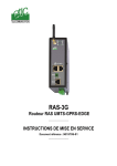
Automation & Drives
Technical Support Information No. 103
Revision 1.0
Process Instrumentation and Analytics - A&D PI 2 - Karlsruhe
February 2004
Page 1 of 1
Information zu / to
Fehlerhafte Pinbelegung des Media Konverter-Spannungsversorgungskabels
Zusammenfassung
Es ist in letzter Zeit häufig vorgefallen, dass in einigen Faseroptik-Board Bausätzen (2017565-806) für den MaxumGC am Anschlussstecker des Spannungsversorgungskabels 2020282-001 zum Media Konverter hin, die
Pinbelegung fehlerhaft ist.
Die Spannungsversorgung von 5 V ist nur dann gewährleistet, wenn das schwarze Kabel direkt neben dem
roten Kabel anliegt (s. Fotos).
Ggf. muss also vor Ort die Belegung umkonfiguriert werden.
Incorrect pin assignment of the media converter power supply cable
We had in the near past complaints about the pin assignment at the power supply cable for the fiber optic converter
(2020282-001).
It seems that there are two different versions included in the fiber optic board set 2017565-806 for the Maxum-GC.
The correct power supply (5 V) is only warranted when the black and the red cable at the end to the PC
Media Converter are directly side by side. See attached images, please!
Bild 1 & 2: Auslieferungszustände des Spannungsversorgungskabels 2020282-001 zum PC Media Konverter
Picture 1 & 2: Delivery status power cable 2020282-001 to the PC Media Converter
Bild 3 & 4: Anschlüsse des Spannungsversorgungskabels 2020282-001 im Maxum II (PC Media Konverter <> SYSCON)
Picture 3 & 4: Power cable 2020282-001 connections on Maxum II (PC Media Converter <> SYSCON)
© SIEMENS AG Karlsruhe - A&D PI 2 AS 2 - Niko Benas +49 721 595 7216 / [email protected]
PC Media Converters
Installation Guide
LE6601C
LE6602C
LE6606C
LE6603C
LE6607C
LE6604C
LE6608C
LE6605C
LE6609C
PC Media Converter™ is a fixed-configuration, IEEE 802.3 singleconversion PC Media Converter Adapter that is designed to convert
RJ-45 (10Base-T twisted pair), BNC (10Base-2 thin coax), ST or SC
(10Base-FL 850 nm multi-mode, 1300 nm multi-mode or single-mode)
fiber. PC Media Converter can be mounted in any PC with a standard
ISA or PCI slot. All versions of PC Media Converters include diagnostic
LEDs for each port and a 4-pin peripheral power supply connector.
The following PC Media Converter versions are available:
UTP/FO — 10Base-T twisted pair/10Base-FL 850 nm multi-mode
fiber; includes one RJ-45 connector and one pair ST
(LE6601C) or SC (LE6602C) connectors
UTP/FO 1300 — 10Base-T twisted pair/10Base-FL 1300 nm multimode fiber; includes one RJ-45 connector and one pair
ST (LE6603C) or SC (LE6604C) connectors
UTP/FO-SingleMode — 10Base-T twisted pair/10Base-FL 1300 nm
single-mode fiber; includes one RJ-45 connector and one
pair ST (LE6605C) or SC (LE6606C) connectors
UTP/FO-SingleMode/PLUS — same as above with higher power
budget; includes one pair ST (LE6607C) or SC (LE6608C)
connectors
UTP/BNC — 10Base-T twisted pair/10Base-2 thin coaxial; includes
one RJ-45 connector and one BNC connector (LE6609C)
Installing PC Media Converter
To install PC Media Converter, turn off the power on your PC and
remove the cover. Find an empty ISA or PCI slot and align PC Media
Converter in the slot. Then
mount PC Media Converter by
screwing its bracket to the
computer casing.
Converter. Attach the male end of the “Y” connector to a standard size
power connector in your computer. Replace the cover. Attach the
cables between PC Media Converter and the devices that will be
interconnected.
NOTE: PC Media Converter only needs power from the computer; no
additional power source is necessary.
After installation, you can configure PC Media Converter for the
following features, depending on the requirements of your installation:
•
•
•
•
Crossover/pass-through connection on the twisted pair port
BNC Port Termintation
FiberAlert
LinkLoss
Twisted Pair Crossover/Pass-Through Switch
Each twisted pair port on PC Media Converter has one RJ-45 connector
for a single shielded or unshielded twisted pair link segment, and features
a push-button, located next to the TP connector, for selecting a crossover
workstation connection or pass-through repeater/hub connection. To
select a pass-through connection, simply press the push-button IN. A
crossover connection is selected when the push-button is OUT.
BNC Port Termination
PC Media Converter UTP/BNC features a 2-position switch next to the
BNC connector that allows a thin coaxial
segment to be terminated at the port without
an additional ‘T’ connector and terminator.
If PC Media Converter UTP/BNC is attached
to a mid-point of a thin Ethernet segment,
attach a ‘T’ connector to the BNC port.
Termination must be OFF (disabled).
Termination is disabled when the toggle is in the left position.
If a thin Ethernet segment is to be terminated at the PC Media
Converter UTP/BNC, attach the cable directly to the BNC connector and
set the termination to ON (enabled – factory default). Toggle the switch
to the ON position to enable termination.
Troubleshooting with LinkLoss and FiberAlert
NOTE: PC Media Converter does
not plug into the mother board.
Also, make sure PC Media
Converter does not extend past
the edge of your case.
LinkLoss and FiberAlert are advanced troubleshooting features that can
help you use your PC Media Converter to locate “silent failures” on your
network. It is vital that you understand exactly how FiberAlert and
LinkLoss work and how they will react in your network configuration
before attempting to use your PC Media Converter.
Attach the keyed mini-power
connector to PC Media
1
2
Enabling and Using FiberAlert and LinkLoss
FiberAlert and LinkLoss are configured on PC Media Converter by
adjusting a two-position switch located on the faceplate, next to the fiber
connectors. The switch for LinkLoss is labeled “LL.” The switch for
FiberAlert is labeled “FA.” Enable LinkLoss or FiberAlert by moving the
corresponding switch to the up (ON) position. Disable either (default) by
moving the switch to the down (OFF) position.
In a central site to remote site media conversion, the manufacturer
recommends you enable your PC Media Converters’ troubleshooting
features as follows: FiberAlert on the remote site only, and LinkLoss on
both the central and remote site. This will ensure that most faults can be
detected by an administrator located at the central site, no matter where
they occur on the network.
Installation Troubleshooting
•
•
•
During installation, first test your fiber and twisted pair
connections with all troubleshooting features disabled. Then
enable these features, if desired, just before final installation.
This will reduce the features’ interference with testing.
To test PC Media Converter by itself, you must have an
appropriate fiber patch cable. First, connect PC Media Converter
to the twisted pair device with a twisted pair cable. Next, loop a
single strand of fiber from the transmit port to the receive port of
your media converter. Finally, verify that you have both twisted
pair and fiber link on your PC Media Converter.
Make sure that you are using the appropriate twisted pair cable
or have the crossover/pass-through button on the PC Media
Converter set correctly.
LED Operation
PC Media Converter features diagnostic LEDs. LED functions on PC
Media Converter TX/FX and PC Media Converter UTP/FO are:
Crossover/
pass-through
switch
BNC
Termination ThinCoaxial
switch
port
Twisted Pair
port
LEDs
X II
10 Mbps
TERM
OFF
FX RCV
TX LNK
FA
FX LNK
Twisted Pair
port FiberAlert and
Crossover/
LinkLoss Fiber Optic
pass-through
switches
port LEDs
switch
X II
TP RCV
TP LNK
BNC COL
BNC RCV
10 Mbps
ON
XMT
LL FA
RCV
FO RCV
TP LNK
FA
FO LNK
Flickers amber when fiber port is receiving data
Glows green when a twisted pair link is established
Glows green when FiberAlert is enabled
Glows green when a fiber link is established
Installing modules without understanding the effects of
LinkLoss and FiberAlert can cause perfectly funcitoning units
to apear flawed or even dead!
If you are unfamiliar with LinkLoss and FiberAlert, the manufacturer
strongly encourages you to read the following information.
About Link Integrity
During normal operation, link integrity pulses are transmitted by all
point-to-point Ethernet devices. When a PC Media Converter receives
valid link pulses, it knows that the device to which it is connected is up
and sending pulses, and that the copper or fiber cable coming from that
device is intact. The appropriate “LINK” LED is lit to indicate this. The
PC Media Converter also sends out link pulses from its copper and fiber
transmitters, but normally has no way of knowing whether the cable to
the other device is intact and the link pulses are reaching the other end.
The combination of FiberAlert and LinkLoss allows this information to be
obtained, even when physical access to a remote device (and its link
integrity LED) is not available.
What Is FiberAlert?
Local Site
FiberAlert lets you know when a
Cable Break
XMT
fault occurs on your fiber loop by
Remote Site
stopping data transmissions and
RCV
RCV
affecting fiber LEDs on both sides of
LED
your network. If a media converter
XMT
is not receiving a fiberlink, FiberAlert
Black Box product with FiberAlert enabled —
disables the media converter's fiber
Remote Site stops transmitting
Local
Link LED is OFF indicating a break in the fiber loop
transmitter, thus mirroring the link
status of the opposite end of the fiber. Both fiber link LEDs on either
end of the link should extinguish, alerting you to the fault.
X
LED OFF = Broken Link
Using FiberAlert, a local site administrator is notified of a fault and
can quickly determine where a cable fault is located without having
to go to the remote site.
NOTE: FiberAlert should only be enabled on one side of a media
conversion. Enabling it on both sides would keep both
transmitters off indefinitely.
What Is LinkLoss?
LinkLoss functions much like FiberAlert in that faults on one port are
mirrored on the other. In the case of LinkLoss, however, a fault on the
fiber port is passed to the Ethernet twisted pair port. If a PC Media
Converter is not receiving a fiber link, LinkLoss disables the transmitter
on the PC Media Converter's twisted pair port. This results in a loss of
link on the remote twisted pair device.
4
3
The LED functions on PC Media Converter UTP/BNC are as follows:
TP RCV
Flickers amber when twisted pair port is receiving data
TP LNK
Glows green when a twisted pair link is established
BNC COL Flickers red in normal operation indicating normal
collisions are being detected on the BNC segment
BNC RCV Flickers amber when BNC port is receiving data
Black Box Customer Service Information
(724) 746-5500 7 a.m. Monday to midnight Friday;
8 a.m. to 4 p.m. Saturday (EST)
FAX:
(724) 746-0746 7 a.m. Monday to midnight Friday;
8 a.m. to 4 p.m. Saturday (EST)
Mail Order: Black Box Corporation, 1000 Park Drive,
Lawrence, PA 15055-1018
Technical support, phone and fax orders 24 hours a day.
CALL:
WARNING! Integrated circuits and fiber optic components are extremely
susceptible to electro-static discharge damage. Do not handle these
components directly unless you are a qualified service technician and use
tools and techniques that conform to accepted industry practices.
3) Hold boards by the edges only; do not touch the electronic components or gold
connectors.
4) After removal, always place the boards on a grounded, static-free surface, ESD
pad or in a proper ESD bag. Do not slide the board over any surface.
*Please contact Black Box for complete warranty, FCC and Safety Certification
information.
Fiber Optic Cleaning Guidelines
Fiber Optic transmitters and receivers are extremely susceptible to contamination by
particles of dirt or dust, which can obstruct the optic path and cause performance
degradation. Good system performance requires clean optics and connector ferrules.
1) Use fiber patch cords (or connectors, if you terminate your own fiber) only from a
reputable supplier; low-quality components can cause many hard-to-diagnose
problems in an installation.
2) Dust caps are installed by the manufacturer to ensure factory-clean optical devices.
These protective caps should not be removed until the moment of connecting the
fiber cable to the device. Assure that the fiber is properly terminated, polished and
free of any dust or dirt, and that the location is as free from dust and dirt as
possible.
3) Store spare caps in a dust-free environment such as a sealed plastic bag or box so
that when reinstalled they do not introduce any contamination to the optics.
4) Should it be necessary to disconnect the fiber device, reinstall the protective dust
caps.
5) If you suspect that the optics have been contaminated, alternate between blasting
with clean, dry, compressed air and flushing with methanol to remove particles of
dirt.
Electrostatic Discharge Precautions
Electrostatic discharge (ESD) can cause damage to your add-in modules. Always
observe the following precautions when installing or handling an add-in module or any
board assembly.
1) Do not remove unit from its protective packaging until you’re ready to install it.
2) Wear an ESD wrist grounding strap before handling any module or component. If
you do not have a wrist strap, maintain grounded contact with the system unit
throughout any procedure requiring ESD protection.
1000 Park Drive • Lawrence, PA 15055-1018 USA
TEL: (724) 746-5500 • FAX: (724) 746-0746
www.blackbox.com
© 1998 - 2001 Black Box Corporation. All rights reserved.
The information in this document is subject to change without notice. Black Box Corporation assumes no
responsibility for any errors that may appear in this document. Specific brands and product names may be
trademarks and are the property of their respective companies.
Document Number 55-80246BB-00 A0
5
July 2001
6