1
Owner's Manual
[RI:IFTSMI:IN°
19.5 HP
ELECTRIC START
42,' MOWER
6 SPEED TRANSAXLE
LAWN TRACTOR
Model No.
917.270811
• Safety
• Assembly
• Operation
• Maintenance
• Repair Parts
CAUTION:
Read and follow all
Safety Rules and Instructions
before operating this equipment.
Sears,
Roebuck
and Co., Hoffman
For answers to your questions
about this product, Call:
1-800-659-5917
Sears Craftsman Help Line
5 am - 5 pro, Mon- Sat
Estates,
IL 60179
W.arranty .:..:.....: ............ "._..-.._i.-.--' ......... 2
......
Prod_'t_Specit_tion's
Asseml:
.........2
._....;.-':._..._.;i.......... 5
...... _............ _...... ,...... _......... 8
..... •_..;_; ...... _...... :...... ; ....... 12
Schei_rule ...t ............. , ....... 18
Maintenance .........................................
18
Service and Adjustments ...................... 22
Storage .................................................
28
Troubleshooting ....................................
29
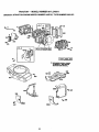
Repair Parts .........................................
34
Parts Ordering ....................... Back Cover
CRAFTSMAN
RIDING
EQUIPMENT
For two i2) _
dat_ of purchase, if this Craftsman Riding Equipment is mainta ned, Ubric_te(j and tuned u_oaci;ording to the instructions in the owner's manual,
Sears w!ll rel_air pr replace, free o! charge, any parts found to be defective in material or
workmanship.
_,
This Warranty does not cover:
• Expendable items which become worn during normal use, such as blades, spark
plugs, air cleaners, belts, etc.
• Tire replacement or repair caused by punctures from outside objects, such as nails,
thorns, stumps, or glass.
• Repairs necessary because of operator abuse, negligence, improper storage or accident or the failure to maintain the equipment according to the instructions contained in
the owner's manual.
• Riding equipment used for commercial
LIMITED
90 DAY WARRANTY
or rental purposes.
ON BATI'ERY
For ninety (90) days from date of purchase, if any battery included with this riding equipment proves defective in matedal or workmanship and our testing determines the battery will not hold a charge,oSears will replace the battery at no charge. In-home warranty
service on your Craftsman riding equipment is available at no charge for 30 days from
the date of purchase. Please contact your nearest service center. After 30 days from the
date of purchase, warranty service is available by taking your Craftsman riding equipment to your nearest Sears Service Center. (In-home warranty service will still be available after 30 days from the date of purchase but a standard trip charge will apply). This
warranty applies only while this product is in the United States. This Warranty gives you
specific legal rights, and you may also have other rights which may vary from state to
state.
Sears, Roebuck and Co., D/817 WA, Hoffman Estates, IL 60179
m
GENERAL OPERATION
• Read, understand, and follow all instructions in the manual and on the machine
before starting.
• On!y allow responsible adults, who are
familiar with the instructions, to operate
the machine.
• Clear the area of objects such as rocks,
toys, wire, etc., which could be picked
up and thrown by the blade.
• Be sure the area is clear of other people
before n_owing. Stop machine if anyone
enters the area.
• Never carry passengers.
• Do not mow in reverse unless absolutely necessary. Always look down and
behind before and while backing.
• Be aware of the mower discharge direction and do not point it at anyone. Do
not operate the mower without either
the entire grass catcher or the guard in
place.
• Slow down before turning.
• Never leave a running machine unattended. Always turn off blades, set parking brake, stop engine, and remove
keys before .dismounting.
• Turn off blades when not mowing.
• Stop engine before removing grass
catcher or unclogging chute.
• Mow only in daylight or good artificial
light.
• Do not operate the machine while under
the influence of alcohol or drugs.
• Watch for traffic when operating near or
crossing roadways.
• Use extra care when loading or unloading the machine into a trailer or truck.
SLOPE
OPERATION
Slopes are a major factor related to lossof-control and tipover accidents, which
can result in severe injury or death. All
slopes require extra caution. If you cannot
back up the slope or if you feel uneasy on
it, do not mow it.
DO:
• Mow up and down slopes, not across.
• Remove obstacles such as rocks, tree
limbs, etc.
• Watch for holes, ruts, or bumps. Uneven
terrain could overturn the machine. Tall
grass can hide obstacles.
• Use slow speed. Choose a low gear so
that you will not have to stop or shift
while on the slope.
• Follow the manufacturer's recommen-
• Do not try to stabilize the machine by
putting your foot on the ground.
• Do not use grass catcher on steep
slopes.
CHILDREN
'
Tragic accidents can occur if the operator
is not alert to the presence of children.
Children are often attracted to the
machine and the mowing activity. Never
assume that children will remain where
you last saw them.
• Keep children out of the mowing area
and under the watchful care of another
responsible adult.
• Be alert and tum machine off if children
enter the area.
• Before and when backing, look behind
and down for small children.
• Never carry children. They may fall off
and be seriously injured or interfere with
safe machine operation.
• Never allow children to operate the
machine.
• Use extra care when approaching blind
comers, shrubs, trees, or other objects
that may obscure vision.
SERVICE
• Use extra care in handling gasoline and
other fuels. They are flammable and
vapors are explosive.
Use only an approved container.
Never remove gas cap or add fuel
with the engine running. Allow engine to cool before refueling. Do not
smoke.
Never refuel the machine indoors.
Never store the machine or fuel
container inside where there is an
dations for wheel weights or counterweights to improve stability.
• Use extra care with grass catchers or
other attachments. These can change
the stability of the machine.
• Keep all movement on the slopes slow
and gradual. Do not make sudden
changes in speed or direction.
• Avoid starting or stopping on a slope. If
tires lose traction, disengage the blades
and proceed slowly s_aig_t down the
slope.
DO NOT:
• Donotturn
on slopes unless necessary,
and then, turn slowly and gradually
downhill, if possible.
• Do not mow near drop-offs, ditches, or
embankments. The mower could sud-
open flame, such as a water heater.
• Never run a machine inside a closed
area.
Keep nuts and bolts, especially blade
attachment bolts, tight and keep equipment in good condition.
Never tamper with safety devices.
Check their proper operation regularly.
Keep machine free of grass, leaves, or
other debris build-up. Clean oil or fuel
spillage. Allow machine to cool before
storing.
Stop and inspect the equipment if you
strike an object. Repair, if necessary,
before restarting.
denly turn over if a wheel is over the
edge of a cliff or ditch, or if an edge
caves in.
• Do not mow on wet grass. Reduced
tractS-oncould cause sliding.
3
•
Never make adjustments
or repairs with
the engine running.
• Grass catcher components are subject
to wear, damage, and deterioration,
which could expose moving parts or
allow objects to be thrown. Frequently
check components and replace with
manufacturer's recommended parts,
when necessary.
• Mower blades are sharp and can cut.
Wrap the blade(s) or wear gloves, and
use extra caution when servicing them.
• Check brake operation frequently.
Adjust and service as required.
• Be sure the area is clear of other people
before mowing. Stop machine if anyone
ehters the area.
• Mow up and down slopes (15 ° Max), not
across.
• Remove obstacles such as rocks, tree
limbs, etc.
• Watch for holes, ruts, or bumps. Uneven
terrain could overtum the machine. Tall
• Never carry passengers.
• Do not mow in reverse unless absolutely necessary. Always look down and
behind before and while backing.
• Never carry children. They may fall off
and be seriously injured or interfere with
safe machine operation.
• Keep children out of the mowing area
and under the watchful care of another
responsible adult.
Be alert and turn machine off if children
enter the area.
• Before and when backing, look behind
and down for small children.
grass can hide obstacles.
• Use slow speed. Choose a low gear so
that you will not have to stop or shift
while on the slope.
• Avoid starting or stopping on a slope. If
tires lose traction, disengage the blades
and proceed slowly straight down the
slope.
• Do notturn on slopes unless necessary,
and then, tum slowly and gradually
downhill, if possible.
_,Look
for this symbol to point out important safety precautions. It means CAUTION!H BECOME AWARE!!! YOUR SAFETY IS INVOLVED.
AWARNING:
The engine exhaust from
this product contains chemicals known to
the State of California to cause cancer,
birth defects, or other reproductive harm.
,
ACAUTION:
In order
,w to prevent accidental starting when setting up, transporting,
adjusting or making repa'_'s _Sways disconnect spark plug wire and place wire where
it cannot contact spark plug.
4
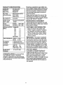
PRODUCT SPECIFICATIONS
GASOLINE
3.5GALLONS
CAPACITY
UNLEADED
ANDTYPE:
REGULAR
OILTYPE
SAE30 (above32°F)
API-SF/SG/SH): SAE5W-30
(below32°F)
OILCAPACITY: 3.0PINTS
SPARKPLUG:
(GAP: .030")
Champion RJ19LM OR
J19LM
VALVE
CLEARANCE:
INTAKE:
.004"-.006"
EXHAUST: .007"-.009"
GROUND
FORWARD:
I sT
SPEED
(MPH):
2 ND
3 RD
4TM
5 TM
6 TM
REVERSE:
Should you experience any problem you
cannot easily remedy, please contact your
nearest Sears Authorized Service Center.
We have competent, well-trained technicians and the proper tools to service or
repair this tractor.
Please read and retain this manual. The
instructions will enable you to assemble
and maintain your tractor properly. Always
observe the "SAFETY RULES".
MAINTENANCEAGREEMENT
A Sears Maintenance Agreement is available on this product. Contact your nearest
Sears store for details.
CUSTOMER
1.1
1.5
2.3
3.5
4.7
5.4
1.5
TIRE PRESSURE:
FRONT:
REAR:
CHARGING
_YSTEM:
3 AMPS BA3-FERY
5 AMPS HEADLIGHTS
BA'FFERY:
AMP/HR:
• Read and observe the safety rules.
• Follow a regular schedule in maintaining, caring for and using your tractor.
• Follow the instructions under"Maintenance" and "Storage"
owner's manual.
sections of this
_,WARNING:
This tractor is equipped
with an internal combustion engine and
should not be used on or near any unimproved forest-covered, brush-covered or
grass-covered land unless the engine's
exhaust system is equipped with a spark
arrester meeting applicable local or state
laws (if any). If a spark arrester is used, it
should be maintained in effective working
order by the operator.
In the state of California the above is
14 PSI
10 PSI
30
MIN. CCA:
240
CASE SIZE: UIR
BLADE BOLT
TORQUE:
RESPONSIBILITIES
27-35 FT. LBS.
required by law (Section 4442 of the
California Public Resources Code). Other
states may have similar laws. Federal
laws apply on federal lands. A spark
arrester for the muffler is available through
your nearest Sears Authodzed Service
Center (See REPAIR PARTS section of
this manual).
CONGRATULATIONS
on your purchase
of a Craftsman Tractor. It has been
designed, engineered and manufactured
to give you the best possible dependability
and performance.
5
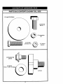
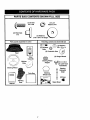
PARTS BAG CONTENTS SHOWN FULL SIZE
(1) Large Flat Washer
(1) Hex Bolt
3/8-16 x 1
(1) Lockwasher
3/8
(1) Hex Bolt
5/16-18x 1-1/4
(1) Locknut
5/16-18
(1) Shoulder Bolt
5/16-18
(1) Washer
17/32 x 1-3/
©
(1) Knob
6
PARTS BAG CONTENTS SHOWN FULL SIZE
/
i,
(2) Screws
_
#10x5/8
Parts packet separately in carton
/_
(2) Lock
_
Washers#t0
Parts Bag contents not shown full size
_m
(2) Shoulder
3/8 x 7/8 x 14
_
(_
(2) Washers/iF;-;-;-;--_k_
Bolts
(2) Centedock Nuts (_' _)'))
Seat
(2) Gauge Wheels
I/
Cassette
//
_i_
Mulcher
Plate_)
Steering
Wheel
Adapter
..J_-
I
Manual
,
:
Steering
Extension
Shaft
c
(2) Keys
Steering
Wheel Insert
I
Steering
Boot
k
Assemblies
PartsBag
o
_oo
4
I
I
I
I
I
Slope Sheet
7
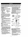
Your new tractor has been assembled at the factory with exception of those parts left
unassembled
for shipping purposes. To ensure safe and proper operation of your tractor
all parts and hardware you assemble must be tightened securely. Use the correct tools
as necessary to insure proper tightness. Review the video cassette before you begin.
TOOLS
REQUIRED
FOR
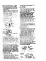
• Position steering wheel so cross bars
are horizontal (left to right) and slide
inside boot and onto adapter.
• Assemble large flat washer, 3/8 lock
washer, 3/8 hex bolt and tighten securely.
• Snap steering wheel insert into center
of steering wheel.
• Remove protective materials from tractor hood and grill.
IMPORTANT: Check for and remove any
staples in skid that may puncture tires
where tractor is to roll off skid.
ASSEMBLY
A socket wrench set will make assembly
easier. Standard wrench sizes you need
are listed below.
(1) 9/16" wrench
(1) Phillips Screwdriver
(1) Utility knife
(1) 3/4" socket with
drive ratchet
(2) 1/2" wrench
(1) Pliers
(1) Tire pressure
gauge
When right or left hand is mentioned in
this manual, it means, from your point of
view, when you are in the operating position (seated behind the steering wheel).
TO REMOVE
CARTON
UNPACK
TRACTOR
Insert
FROM
_..
3/8 Lockwasher
CARTON
• Remove all accessible loose parts and
parts boxes from shipping carton (See
page 6).
• Cut, from top to bottom, along lines on
all four corners of shipping carton, and
lay panels flat.
• Check for any additional loose parts or
boxes and remove.
Steering
Wheel
_
Steering
BEFORE ROLLING TRACTOR OFF
SKID
ATTACH
STEERING
ASSEMBLE
BOOT
WHEEL
EXTENSION
• Slide-extension
SHAFT AND
sh_'ft onto lower steer-
ing shaft. Align mounting holes in extension and lower shafts _d=i_stall
5/16
hex bolt and Iocknut. Tighten securely.
IMPORTANT: Tighten bolt and nut securely to 18-22 ft. lbs. torque.
• Place tabs of steering boot over tab
slots in dash and push down to secure.
INSTALL STEERING
TO ROLL TRACTOR OFF SKID (See
Operation section for location and
function
of controls)
• Press lift lever plunger and raise attachment lift lever to its highest position.
• Release parking brake by depressing
clutch/brake pedal.
• Place gearshift lever in neutral (N) position.
• Roll tractor forward off skid.
WHEEL
• Position front wheels of the tractor so
they are pointing straight forward.
• Slide steering wheel adapter onto steering shaft extension.
• Remove banding holding discharge
guard up against tractor.
8
HOW TO SET UP YOUR TRACTOR
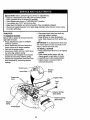
CONNECT BATTERY
• Lift hood to raised position.
• If this battery is put into service after
month and year indicated on label (label
located between terminals) charge battery for minimum of one hour at 6-10
amps. (See "BATTERY" in
MAINTENANCE
section of this manual
for charging
.. ....
instructions).
.
_
/Label
right position.
• Place front of mulcher plate over front of
mower deck opening and slide into
place, as shown.
• Hook front latch into hole on front of
mower deck.
• Hook rear latch into hole on back of
mower deck.
_,CAUTION:
Do not remove discharge
guard from mower. Raise and hold guard
when attaching mulcher plate and allow it
to rest on plate while in operation.
" "",...,.,%
INSTALL
INSTALL MULCHER PLATE
• Install two latch hooks to mulcher plate
using screw, washer, lock washer, and
weld nut as shown.
NOTE: Pre-assemble weld nut to latch
hook by inserting weld nut from the top
with hook pointing down.
• Tighten hardware securely.
• Raise and hold deflector shield in up-
Weld Nut From
The Top
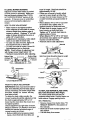
SEAT
Adjust seat before tightening adjustment
knob.
• Remove cardboard packing on seat pan.
• Place seat on seat pan and assemble
shoulder bolt. Tighten shoulder bolt
securely.
• Assemble adjustment knob and flat
washer loosely. Do not tighten.
• Lower seat into operating position and
sit on seat.
• Slide seat until a comfortable position is
reached which allows you to press
clutch/brake pedal all the way down.
• Get off seat without moving its adjusted
position.
• Raise seat and tighten adjustment knob
securely.
"
Weld
Hook Points
Down
Lock
Washer
Latch
Latch
I Nut
Lock Washer
Washer
Washer
Mulcher
Plate
'_.IScrew
Deflector
_'eat
Seat Pan
Shoulder
Bolt
Flat Washer
Adjustment Knob
9
TO CONVERTTO BAGGINGOR
DISCHARGING
Simplyremovemulcherplateandstorein
a safeplace.Yourmoweris nowreadyfor
discharging or installation of optional
grass catcher accessory.
NOTE: It is not necessary to change
blades. The mulcher blades are designed
for discharging and bagging also.
ASSEMBLE
GAUGE
MOWER DECK
WHEELS
TO
The gauge wheels are designed to keep
the mower deck in proper position when
operating mower. Be sure they are properly adjusted to ensure optimum mower
performance.
• Assemble gauge wheels with tractor on
a flat level surface.
• Adjust mower to desired cutting height
(See "TO ADJUST MOWER CUTTING
HEIGHT" in the Operation section of
this manual).
• With mower in desired height of cut
position, gauge wheels should be
assembled so they are slightly off the
ground. Install gauge wheel in appropriate hole with shoulder bolt, 3/8 washer,
and 3/8-16 locknut and tighten securely.
• Repeat for opposite side installing
gauge wheel in same adjustment hole.
Gauge Wheel Mounting
Bracke
_
"_\_i
"\ "- _'_'%L_":_,_
j,
Locknut-
_;';_.@..,_F'>\'_'_
/
i_,._ _Shoulder
3/8Washer-/-.
"_
Gauge Wheel
10
Bolt
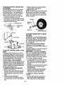
CHECKTIRE PRESSURE
The tires on yourtractorwereoverinflated
at the factory for shipping purposes.
Correct tire pressure is important for best
cutting performance.
• Reduce tire pressure to PSI shown in
"PRODUCT SPECIFICATIONS"
section
of this manual.
CHECK
DECK LEVELNESS
For best cutting results, mower housing
should be properly leveled. See "TO
LEVEL MOWER HOUSING" in the
Service and Adjustments section of this
manual.
CHECK FOR PROPER
ALL BELTS
POSITION
OF
See the figures that are shown for replacing motion and mower blade drive belts in
the Service and Adjustments section of
this manual. Verify that the belts are routed correctly.
CHECK
BRAKE
/CHECKUST
PLEASE REVIEWTHEFOLLOWING
CHECKLIS_
4" All assembly instructions have been
completed.
4" No remaining loose parts in carton.
,/ Battery is properly prepared and
charged. (Minimum 1 hour at 6 amps).
/ Seat is adjusted comfortably and
tightened securely.
4' All tires are properly inflated. (For
shipping purposes, the tires were
overinflated at the factory).
,,f Be sure mower deck is properly leveled
side-to-side/front-to-rear
for best
cutting results. (Tires must be propedy
inflated for leveling).
4" Check mower and drive belts. Be sure
they are routed properly around pulleys
and inside all belt keepers.
J
SYSTEM
After you learn how to operate your tractor, check to see that the brake is propedy
adjusted. See "TO ADJUST BRAKE" in
the Service and Adjustments section of
this manual.
Check wiring. See that all connections
are still secure and wires are properly
clamped.
WHILE
LEARNING
HOW TO USE YOUR
TRACTOR, PAY EX'FRAA'I-rENTION
TO
THE FOLLOWING
IMPORTANT
ITEMS:
J Engine oil is at proper level.
4' Fuel tank is filled with fresh, clean,
regular unleaded gasoline.
,/ Become familiar with all controls - their
location and function. Operate them
before you start the engine.
4' Be sure brake system is in safe
operating condition.
11
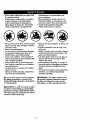
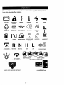
These symbols may appear on your tractor or in literature
Learn and understand their meaning.
BATTERY
CAUTION OR
WARNING
REVERSE
supplied
FORWARD
with the product.
FAST
SLOW
m
FUEL
CHOKE
MOWER HEIGHT
PARKING BRAKE
LOCKED
R N H
ATTACHMENT
CLUTCH ENGAGED
REVERSE
NEUTRAL
UNLOCKED
MOWER LIFT
L
HIGH
LOW
KEEP AREA CLEAR
PARKING BRAKE
SLOPE HAZARDS
ATFACHMENT
IGNITION
(SEE SAFETY RULES SECTION)
CLUTCH DISENGAGED
FREE WHEEL
DANGER, KEEP HANDS AND FEET AWAY
(Automatic Models only)
12"
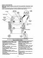
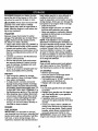
KNOW YOUR TRACTOR
READTHIS OWNER'SMANUALANDSAFETYRULESBEFOREOPERATINGYOUR
TRACTOR
Comparethe illustrationswith yourtractortofamUiarizeyourselfwiththe locationsof
variouscontrolsandadjustments.Savethis manualfor future reference.
Attachment
Clutch Lever
Amme_r
Light
ignition
Switch
Choke Control
Throttle
Control _
Clutch/Brake
Pedal
Lift Lever
Plunger
Attachment Lift
Lever
Brake
Height
Adjustment
Knob
Gearshift
Lever
Our tractors conform to the safety standards of the American
National Standards Institute.
ATTACHMENT
CLUTCH
LEVER:
HEIGHT ADJUSTMENT
Used to
engage the mower blades, or other attachments mounted to your t_actGr.
LIGHT SWITCH:
and off.
KNOB: Used to
adjust the mower cutting height.
GEARSHIFT LEVER: Selects the speed
and direction of tractor.
Turns the headlights on
ATTACHMENT LIFT LEVER: Used to raise,
lower, and adjust the mower deck or other
attachments mounted to your tractor.
LIFT LEVER PLUNGER: Used to release
THROTTLE CONTROL:
Used for starting
and controlling engine speed.
CHOKE CONTROL:
Used when starting a
cold engine.
CLUTCH/BRAKE
PEDAL: Used for
attachment lift lever when changing its position.
declutching and braking the tractor and starting the engine.
IGNITION SWITCH: Used for starting and
stopping the engine.
PARKING BRAKE: Locks clutch/brake pedal
into the-brake position.
AMMETER: Indicates battery charging (+)
or discharging (-).
13
The operationof any
tractor can result in foreign objects thrown into the
eyes, which can result in severe eye damage. Always wear safety glasses or eye shields while operating your tractor or performing any adjustments or repairs. We recommend a wide vision safety mask over spectacles; or standard safety glasses.
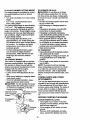
HOW TO USE YOUR TRACTOR
Your tractor is equipped with an operator
presence sensing switch. When engine
is running, any attempt by the operator to
leave the seat without first setting the
parking brake will shut off the engine.
TO SET PARKING BRAKE
• Depress clutch/brake pedal into full
=BRAKE" position and hold.
• Place parking brake lever in
"ENGAGED" position and release pressure from clutch/brake pedal. Pedal
should remain in =BRAKE" position•
Make sure parking brake will hold tractor secure.
Choke Control
Attachment Clutch Lever
"Engaged" Position
Throttle
"Disengaged"
Position
Brake
before stopping may cause engine to
=backfire".
• Turn ignition key to =OFF" position and
remove key. Always remove key when
leaving tractor to prevent unauthorized
use.
• Never use choke to stop engine.
IMPORTANT:
Leaving the ignition switch
in any position other than "OFF" will cause
the battery to be discharged, (dead).
NOTE: Under certain conditions when
tractor is standing idle with the engine running, hot engine exhaust gases may
cause "browning" of grass. To eliminate
this possibility, always stop engine when
stopping tractor on grass areas.
h, CAUTION" Always stop tractor completely, as described above, before leaving
the operator's position; to empty grass
catcher, etc.
THROTTLE
CONTROL
Pedal'Ddve"
Always operate engine at full throttle.
• Operating engine at less than full throttle reduces the battery charging rate.
• Full throttle offers the best bagging and
mower performance.
CHOKE CONTROL
Position
"_'Brake" Gearshift
Adjustment Position Lever
Knob
•Position
Use choke control whenever you are starting a cold engine. Do not use to start a
warm engine.
• To engage choke control, pull knob out.
Slowly push knob in to disengage.
STOPPING
MOWER
BLADES
-
TO MOVE FORWARD AND BACKWARD
The direction and speed of movement is
controlled by the gearshift lever.
• Start tractor with clutch/brake pedal
depressed and gearshift lever in neutral
(N) position.
• Move gearshift lever to desired position.
• Slowly release clutch/brake pedal to
start movement.
IMPORTANT:
Bring tractor to a complete
stop before shifting or changing gears.
Failure to do so will shorten the useful life
• To stop mower blades, move attachment clutch lever to =DISENGAGED"
position.
GROUND
_,
DRIVE
=_
-
• To stop ground drive, depress
clutch/brake pedal into full "BRAKE"
position.
• Move gearshift lever to neutral (N) position.
ENGINE
-
• Move throttle control to slow position.
NOTE: Failure to move throttle control to
slow position and allowing
of your transaxle.
engine to idle
14
TO ADJUST MOWERCUTTINGHEIGHT
The cuttingheightis controlledby tuming
the heightadjustmentknobin desired
direction.
• Turn knob clockwise (G) to raise cutting
height.
• Turn knob counterclockwise (,_)to
lower cutting height.
The cutting height range is approximately
1-1/2" to 4". The heights are measured
from the ground to the blade tip with the
engine not running. These heights are approximate and may vary depending upon
soil conditions, height of grass and types
of grass being mowed.
• The average lawn should be cut to
approximately 2-1/2 inches during the
cool season and to over 3 inches during
hot months. For healthier and better
looking lawns, mow often and after
moderate growth.
• For best cutting performance,
grass
over 6 inches in height should be
mowed twice. Make the first cut relatively high; the second to desired
height.
TO OPERATE MOWER
Your tractor is equipped with an operator
presence sensing switch. Any attempt by
the operator to leave the seat with the
engine running and the attachment clutch
engaged will shut off the engine.
• Select desired height of cut.
• Lower mower with attachment lift control.
• Start mower blades by engaging attachment clutch control.
• TO STOP MOWER BLADES - disen_gcage attachment clutch control.
AUTION:
Do not operate the mower
without either the entire grass catcher,
on mowers so equipped, or the discharge guard in placP_ =,,
Attachment Clutch
Attachment Lift Lever
Lever =Engaged"
Position
Position
_
OPERATE ON HILLS
CAUTION: Do not drive up or down
hills with slopes greater than 15 ° and do
not drive across any slope. A slope guide
at the back of your manual is provided for
your use.
• Choose the slowest speed before starting up or down hills.
• Avoid stopping or changing speed on
hills.
• If slowing is necessary, move throttle
control lever to slower position.
• If stopping is absolutely necessary,
push clutch/brake pedal quickly to brake
position and engage parking brake.
• Move gearshift lever to 1st gear. Be
sure you have allowed room for tractor
to roll slightly as you restart movement.
• To restart movement, slowly release
parking brake and clutch/brake pedal.
• Make all tums slowly.
TO TRANSPORT
• Raise attachment lift to highest position
with attachment lift control.
• When pushing or towing your tractor, be
sure gearshift lever is in neutral (N)
position.
• Do not push or tow tractor at more than
five (5) MPH.
NOTE: To protect hood from damage
when transporting your tractor on a truck
or a trailer, be sure hood is closed and
secured to tractor. Use an apprepdate
means of tying hood to tractor (rope, cord,
etc.).
TOWING CARTS AND OTHER
ATrACHMENTS
Tow only the attachments that are recommended by and comply with specifications
of the manufacturer of your tractor. Use
common sense when towing. Too heavy of
a load, while on a slope, is dangerous.
Tires can lose traction with the ground
and cause you to lose control of your tractor.
BEFORE
Position
.:_-_.Low
Position
Guard
CHECK
STARTING
ENGINE
THE
ENGINE
OIL LEVEL
• The engine in your tractor has been
shipped, from the factory, already filled
with summer weight oil.
• Check engine oil with tractor on level
ground.
• Remove oil fill cap/dipstick and wipe
clean, reinsert the dipstick and screw
15
captight,wait for a few seconds,
removeandread oil level. If necessary,
addoil until "FULL" mark on dipstick is
reached. Do not overfill.
• For cold weather operation you should
change oil for easier starting (See "OIL
VISCOSITY CHART" in the Maintenance section of this manual).
• To change engine oil, see the Maintenance section in this manual.
ADD
GASOLINE
• Fill fuel tank. Use fresh, clean, regular
unleaded gasoline with a minimum of 87
octane. (Use of leaded gasoline will
increase carbon and lead oxide
deposits and reduce valve life). Do not
mix oil with gasoline. Purchase fuel in
quantities that can be used within 30
days to assure fuel freshness.
IMPORTANT: When operating in temperatures below 32°F(0°C), use fresh, clean
winter grade gasoline to help insure good
,_d weather starting.
WARNING: Experience indicates that
alcohol blended fuels (called gasohol or
using ethanol or methanol) can attract
moisture which leads to separation and
formation of acids during storage. Acidic
gas can damage the fuel system of an
engine while in storage. To avoid engine
problems, the fuel system should be emptied before storage of 30 days or longer.
Drain the gas tank, start the engine and let
it run until the fuel lines and carburetor are
• Pull choke control out for a cold engine
start attempt. For a warm engine start
attempt the choke control may not be
needed.
NOTE: Before starting, read the warm and
cold starting procedures below.
• Insert key into ignition and turn key
clockwise to "START" position and
release key as soon as engine starts.
Do not run starter continuously for more
than fifteen seconds per minute. If the
engine does not start after several
attempts, push choke control in, wait a
few minutes and try again. If engine still
does not start, pull the choke control out
and retry.
WARM WEATHER
AND ABOVE)
STARTING
(50 ° F
• When engine starts, slowly push choke
control in until the engine begins to run
smoothly. If the engine starts to run
roughly, pull the choke control out slightly for a few seconds and then continue
to push the control in slowly.
• The attachments and ground drive can
now be used. If the engine does not
accept the load, restart the engine and
allow it to warm up for one minute using
the choke as described above.
COLD WEATHER
BELOW)
STARTING
(50 ° FAND
• When engine starts, slowly push choke
control in until the engine begins to run
smoothly. Continue to push the choke
control in small steps allowing the
engine to accept small changes in
speed and load, until the choke control
is fully in. If the engine starts to run
roughly, pull the choke control out slightly for a few seconds and then continue
to push the control in slowly. This may
require an engine warm-up period from
several seconds to several minutes,
empty. Use fresh fuel next season. See
Storage Instructions for additional information. Never use engine or carburetor
cleaner products in the fuel tank or perma_nt damage may occur.
CAUTION: Fill to _.Itt°m .°f gas tank
filler neck. Do not overfill. W,pe off any
spilled oil or fuel. Do not store, spill or use
gasoline near an open fl_n_
TO START ENGINE
When starting the engine for the first time
or if the engine has run out of fuel, it will
take extra cranking time to move fuel from
the tank to the engine.
• Sit on seat in operating position,
depress clutch/brake pedal and set
parking brake.
• Place gear shift lever in neutral (N)
position.
• Move attachment clutch to =DISENGAGED" position.
• Move throttle control to fast position
depending on the temperature.
• The attachments can be used during
the engine warm-up period and may
require the choke control be pulled out
slightly.
NOTE: A high altitude (above 3000 feet)
or in cold temperatures (below 32 F) the
carburetor fuel mixture may need to be
adjusted for best engine performance.
See "TO ADJUST CARBURETOR"
in the
Service and Adjustments section of this
manual.
16
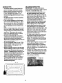
MOWING TIPS
MULCHING
• Tire chains cannot be used when the
IMPORTANT:
For best performance,
keep mower housing free of built-up grass
and trash. Clean after each use.
mower housing is attached to tractor.
• Mower should be properly leveled for
best mowing performance.
See "TO
LEVEL MOWER HOUSING" in the
Service and Adjustments section of this
manual.
• The left hand side of mower should be
used for trimming.
• Drive so that clippings are discharged
onto the area that has been cut. Have
the cut area to the right of the machine.
This will result in a more even distribution of clippings and more uniform cutting.
• When mowing large areas, start by turning to the right so that clippings will discharge away from shrubs, fences, driveways, etc. After one or two rounds,
mow in the opposite direction making
left hand turns until finished
• If grass is extremely tall, it should be
mowed twice to reduce load and possible fire hazard from dried clippings.
Make first cut relatively high; the second
to the desired height.
• Do not mow grass when it is wet. Wet.
grass will plug mower and leave undesirable clumps. Allow grass to dry
before mowing.
• Always operate engine at full throttle
when mowing to assure better mowing
performance and proper discharge of
material. Regulate ground speed by selecting a low enough gear to give the
mower the best cutting performance as
well as the quality of cut desired.
• When operating attachments, select a
ground speed that will suit the terrain
and .giye best performance of the attachment being used.
TIPS
• The special mulching blade will recut
the grass clippings many times and
reduce them in size so that as they fall
onto the lawn they will disperse into the
grass and not be noticed. Also, the
mulched grass will biodegrade quickly
to provide nutrients for the lawn.
Always mulch with your highest engine
(blade) speed as this will provide the
best recutting action of the blades.
• Avoid cutting your lawn when it is wet.
Wet grass tends to form clumps and
interferes with the mulching action. The
best time to mow your lawn is the early
afternoon. At this time the grass has
dried and the newly cut area will not be
exposed to the direct sun.
• For best results, adjust the mower cutting height so that the mower cuts off
only the top one-third of the grass
blades. For extremely heavy mulching,
reduce your width of cut on each pass
and mow slowly.
• Certain types of grass and grass conditions may require that an area be
mulched a second time to completely
hide the clippings. When doing a second cut, mow across or perpendicular to
the first cut path.
• Change your cutting pattern from week
to week. Mow north to south one week
then change to east to west the next
week. This will help prevent matting
and graining of the lawn.
]L
lfi
tL_
MOWING
J
17
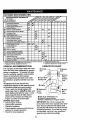
CUSTOMER RESPONSIBILITIES
MAINTENANCE
SCHEDULE
FILL IN DATES
AS YOU COMPLETE
REGULAR
SERVICE
Check
_"_'¢_
fC_'_..._'_C'_':'Ct_.,..-:'_',_
'j_ SERVICE
DA"FES
Brake Operation
Check Tire Pressure
T
R
Check Operator Presence
Interlock Systems
and
ll_
Check for Loose
Fasteners
CA
SharpePJReplace
Mower
T
Lubrication
O
Check
Battery
Level
a
Clean
Battery
end Terminals
Check
Transaxla
Adjust
Blade Belt(s)
Adjust
Motion
Check
Engine
Change
If
Blades
Chart
v"
Cooling
Tension
V'P5
Drive Belt(s) Tension
Oil Level
V'
Engine Oil
E
a
G
Clean
Air Filter
Clean
Air Screen
NI
Replace
E
Clean
Inspect
Muffler/Spark
i,,'
An-ester
Oil Filter (If equipped)
Engk'te Cooling
Fins
Replace
Spark
Plug
Replace
Air Filter Paper
Replace
Fuel Filter
Cartridge
i,,"
1 * Change more Often when o_0orat_
under • heavy load _r in high am_ent
2 - Servicl more often when 0per •_ng _1 d_y or dusty condl_on$.
3 - If equipped with oll filter, change o41==very 50 hours.
GENERAL
temperatures.
5. If equipped wilh adjustable system.
6 - Not required if equipped wiUI malnt ermncr_treo batteP/.
7 - Tighten front u]e pklo_ bolt to 35 ft.*lDe, maximum.
LUBRICATION
RECOMMENDATIONS
The warranty on this tractor does not cover
items that have been subjected to operator
abuse or negligence. To receive full value
from the warranty, operator must maintain
tractor as instructed in this manual.
CHART
Zerk
Zerk
Wheel
O Front Wheel
Bearing Zerk
Some adjustments will need to be made
periodically to properly maintain your tractor.
All adjustments in the Service and
Adjustments section of this manual should
be chedked at least once each season.
Bearing
Zerk
O Engine
I
• Once a year you should replace the
spark plug, clean or rep'lac_ air filter, and
check blades and belts for wear. A new
spark plug and clean air filter assure
proper air-fuel mixture and help your
engine run better and last longer.
BEFORE EACH USE
O Attachment
Clutch
Pivot(s)
,: 0 Geart
shift
, Pivots
O SAE 30 or 10w30 Motor OIL
O General Purpose Grease
O Refer to Maintenance "Engine" Section
IMPORTANT: Do not oil or grease the
pivot points which have special nylon bearings. Viscous lubricants will attract dust
and dirt that will shorten the life of the selflubricating bearings. If you feel they must
be lubricated, use only a dry, powdered
graphite type lubricant sparingly.
•
•
•
•
Check engine oil level.
Check brake operation.
Check tire pressure.
Check operator presence and interlock
systems for proper operation.
• Check for loose fasteners.
18
TRACTOR
Alwaysobservesafetyruleswhen performing any maintenance.
BRAKE OPERATION
If tractor requires more than six (6) feet
stopping distance at high speed in highest
gear, then brake must be adjusted. (See
rl'O ADJUST BRAKE" in the Service and
IMPORTANT: To ensure proper assembly,
center hole isn blade must align with
star on mandrel assembly.
• Reassemble hex bolt, lock washer and
flat washer in exact order as shown.
• Tighten bolt securely (27-35 Ft. Lbs.
torque).
TrailingEdge Up _. ,
MandrelAssembly
_..
u/aoe Center
Adjustments section of this manual).
("(_
Hole ;_
TIRES
• Maintain proper air pressure in all tires
(See =PRODUCT SPECIFICATIONS"
section of this manual).
• Keep tires free of gasoline, oil, or insect
control chemicals which can harm rubber.
• Avoid stumps, stones, deep ruts, sharp
objects and other hazards that may
cause tire damage.
NOTE: To seal tire punctures and prevent
flat tires due to slow leaks, tire sealant
may be purchased from your local parts
dealer. Tire sealant also prevents tire dry
rot and corrosion.
OPERATOR
PRESENCE
SYSTEM
Be sure that operator presence and interlock systems are working properly. If your
tractor does not function as described
below, repair the problem immediately.
• The engine should not start unless the
clutch/brake pedal is fully depressed
and attachment clutch control is in the
disengaged position.
• When the engine is running, any
attempt by the operator to leave the
seat without first setting the parking
brake should shut off the engine.
• When the engine is running and the
attachment clutch is engaged, any
attempt by the operator to leave the
seat Should shut off the engine.
• The attachment clutch should never
operate unless the operator is in the
seat.
BLADE CARE
For best results mower blades must be
kept sharp. Replace bent or damaged
blades.
BLADE
*A Grade 8 heat treated boltcan be identifiedby six
lineson the boltbead.
IMPORTANT:
treated.
Blade bolt is Grade 8 heat
TO SHARPEN
BLADE
NOTE: We do not recommend sharpening
blade, but if you do, be sure the blade is
balanced.
Care should be taken to keep the blade
balanced. An unbalanced blade will cause
excessive vibration and eventual damage
to mower and engine.
• The blade can be sharpened with a file
or on a grinding wheel. Do not attempt
to sharpen while it is on the mower.
• To check blade balance, you will need a
5/8" diameter steel bolt, pin, or a cone
balancer. 0Nhen using a cone balancer,
follow the instructions supplied with balancer).
NOTE: Do not use a nail for balancing
blade. The lobes of the center hole may
appear to be centered, but are not.
• Slide blade onto an unthreaded portion
of the steel bolt or pin and hold the bolt
or pin parallel with the ground. If blade
is balanced, it should remain in a horizontal position. If either end of the blade
moves downward, sharpen the heavy
end until the blade is balanced.
5i8" Bolt
orPin
REMOVAL
.__<_Blade
Center Hole
• Raise mower to highest position to allow
access to blades.
• Remove hex bolt, lock washer and flat
washer securing blade.
• Install new or resharpened blade with
trailing edge up towards deck as shown.
-'_
BATI'ERY
Your tractor has a battery charging system
which is sufficient for normal use.
However, periodic charging of the battery
with an automotive charger will extend its
life.
19
• Keep battery and terminals clean.
• Keep battery bolts tight.
• Keep small vent holes open.
• Recharge at 6-10 amperes for 1 hour.
NOTE: The original equipment battery on
your tractor is maintenance free. Do not
attempt to open or remove caps or covers.
Adding or checking level of electrolyte is
not necessary.
TO CLEAN
BATTERY
level more frequently to avoid possible
engine damage from running low on oil.
Change the oil after every 25 hours of
operation or at least once a year if the
tractor is not used for 25 hours in one
year.
Check the crankcase oil level before starting the engine and after each eight (8)
hours of operation. Tighten oil fill cap/dipstick securely each time you check the oil
level.
AND TERMINALS
Corrosion and dirt on the battery and terminals can cause the battery to "leak"
power.
• Remove terminal guard.
• Disconnect BLACK battery cable first
then RED battery cable and remove
battery from tractor.
• Rinse the battery with plain water and
dry.
• Clean terminals and battery cable ends
with wire brush until bright.
• Coat terminals with grease or petroleum
jelly.
• Reinstall battery (See "REPLACING
BATTERY" in the SERVICE AND
ADJUSTMENTS
section of this manual).
TO CHANGE
ENGINE
OIL
Determine temperature range expected
before oil change. All oil must meet API
service classification SF, SG or SH.
• Be sure tractor is on level surface.
• Oil will drain more freely when warm.
• Catch oil in a suitable container.
• Remove oil fill cap/dipstick. Be careful
not to allow dirt to enter the engine
when changing oil.
• Remove drain plug.
• After oil has drained completely, replace
oil drain plug and tighten securely.
• Refill engine with oil through oil fill dipstick tube. Pour slowly. Do not overfill.
For approximate capacity see "PRODUCT SPECIFICATIONS"
section of this
manual.
V-BELTS
Check V-belts for deterioration and wear
after 100 hours of operation and replace if
necessary. The belts are not adjustable.
Replace belts if they begin to slip from
wear.
TRANSAXLE
COOLING
• Use gauge on oil fill cap/dipstick for
checking level. Be sure dipstick cap is
tightened securely for accurate reading.
Keep oil at "FULL" line on dipstick.
Keep transaxle free from build-up of dirt
and chaff which can restrict cooling.
Air Screen
j_._
Oil Drain _(_-_,
Plug
ENGINE
LUBRICATION
Only use high quality detergent oil rated
with API service clarification
SF, SG or
SH. Select the oil's SAE viscosity grade
Oil nil Cap/Dipstick /
according to your expected o=Reratingtemperature.
SAE VISCC61TY
_
AIR FILTER
Your engine will not run properly using a
dirty air filter. Clean the foam pre-cleaner
after every 25 hours of operation or every
season. Service paper cartridge every
100 hours of operation or every season,
whichever occurs first.
GRADES
*C _o.
2_
30.
TEMPERATURE RANGE ANTICIPATED BEFORE NEXT OIL CHANGE
Service air cleaner more often under dusty
conditions.
NOTE: Although multi-viscosity
oils
(5W30, 10W30 _tc.) improve starting in
cold weather, these multi-viscosity oils will
result in increased oil consumption when
used above 32°F. Check your engine oil
• Remove knob(s) and cover.
TO SERVICE PRE-CLEANER
• Slide foam pre-cleaner off cartridge.
• Wash it in liquid detergent and water.
• Squeeze it dry in a clean cloth.
20
• Saturateit in engineoil. Wrap it in
clean,absorbentcloth andsqueezeto
removeexcessoil.
Top Air Gui_..
Engine Cooling
Fins
• If very dirty or damaged, replace precleaner.
• Reinstall pre-cleaner over cartridge.
• Reinstall cover and secure with knob(s).
TO SERVICE CARTRIDGE
• Remove wing nuts and cartridge plate.
• Carefully remove cartridge to prevent
debris from entering carburetor.
• Clean cartridge by tapping gently on flat
surface. If very dirty or damaged,
replace cartridge.
• Reinstall cartridge plate, wing nuts, precleaner, cover and secure with knob(s).
IMPORTANT:
Petroleum solvents, such
as kerosene, are not to be used to clean
the cartridge. They may cause deterioration of the cartridge. Do not oil cartridge.
Do not use pressurized air to clean or dry
cartridge.
Cover
Knob
Cover
(Both
Sides)
Inspect and replace corroded muffler and
spark arrester (if equipped) as it could create a fire hazard and/or damage.
SPARK PLUGS
Replace spark plugs at the beginning of
each mowing season or after every 100
hours of operation, whichever occurs first.
Spark plug type and gap setting are
shown in =PRODUCT SPECIFICATIONS"
section of this manual.
IN-LINE FUEL RLTER
The fuel filter should be replaced once
each season. If fuel filter becomes
clogged, obstructing fuel flow to carburetor, replacement is required.
• With engine cool, remove filter and plug
fuel line sections.
Foam
Pre-Cleaner
• Place new fuel filter in position in fuel
line with arrow pointing towards carburetor.
• Be sure there are no fuel line leaks and
Air Scre_
CLEAN
•
MUFFLER
Cartridge
Plate
Wing Nut
"_
•
clamps are properly positioned.
• Immediately wipe up any spilled gasoline.
AIR SCREEN
Air screen must be kept free of dirt and
chaff to prevent engine damage from overheating. Clean with a wire brush or compressed air to remove dirt and stubborn
dried gum fibers.
ENGINE COOLING FINS
Remove any dust, dirt of, oiljrom engine
cooling fins to prevent engine damage
from overheating. Air guide covers must
be removed. Remove side panels and
hood (See =-I'O REMOVE HOOD AND
GRILLASSEMBLY"
in the Service and Ad-
CLEANING
• Clean engine, battery, seat, finish, etc.
of all foreign matter.
• Keep finished surfaces and wheels free
of all gasoline, oil, etc.
• Protect painted surfaces with automotive type wax.
We do not recommend using a garden
hose to clean your tractor unless the electrical system, muffler, air filter and carburetor are covered to keep water out. Water
in engine can result in a shortened engine
life.
justments section of this manual).
21
_CAUTION:
Before performing any service or adjustments:
• Depress clutch/brake pedal fully and set parking brake.
• Place gearshift lever in neutral (N) position.
• Place attachment clutch in "DISENGAGED"
position.
• Turn ignition key "OFF" and remove key.
• Make sure the blades and all moving parts have completely stopped.
• Disconnect spark plug wire from spark plug and place wire where it cannot come
in contact with plug.
TRACTOR
• Disconnect front links from deck by
removing retainer springs.
• Raise lift lever to raise suspension
arms. Slide mower out from under tractor.
IMPORTANT: If an attachment other than
the mower deck is to be mounted on the
TO REMOVE MowER
Mower will be easier to remove from the
right side of tractor.
• Place attachment clutch in "DISENGAGED" position.
• Move attachment lift lever forward to
tractor, remove the front links.
TO INSTALL MOWER
lower mower to its lowest position.
• Roll belt off engine pulley.
• Disconnect clutch rod from clutch lever
• Raise attachment lift lever to its highest
position.
• Slide mower under tractor with dis-
by removing retainer spring.
• Disconnect anti-swaybar from chassis
bracket by removing retainer spring.
• Disconnect suspension arms from rear
deck brackets by removing retainer
springs.
charge guard to right side of tractor.
• Lower lift lever to its lowest position.
• Install mower in reverse order of
removal instructions.
Retainer
Suspension
Arms
Pulley
Front
Link
(Both Sides)
(Both Sides)
Retainer
Spdng
Anti-Swaybar
22
TO LEVELMOWERHOUSING
Adjustthe mowerwhile tractoris parked
on levelgroundor driveway. Makesure
tires areproperlyinflated (See =PRODUCT SPECIFICATIONS"
section of this
manual).
If tires are over or underinflated, you will not properly adjust your
mower.
SIDE-TO-SIDE
ADJUSTMENT
• Raise mower to its highest position.
• At the midpoint of both sides of mower,
measure height from bottom edge of
mower to ground.
Distance "A" on both
sides of mower should be the same or
within 1/4" of each other.
• If adjustment is necessary, make adjustment on one side of mower only.
• To raise one side of mower, tighten lift
link adjustment nut on that side.
• To lower one side of mower, loosen lift
equal in length. Both links should be
approximately 10-3/8".
• If links are not equal in length, adjust
one link to same length as other link.
• To lower front of mower loosen nut "E"
on both front links an equal number of
turns.
• When distance "D" is 1/8" to 1/2" lower
at front than rear, tighten nuts "1_'
against trunnion on both front links.
• To raise front of mower, loosen nut "F"
from trunnion on both front links.
Tighten nut "E" on both front links an
equal number of tums.
• When distance =D" is 1/8" to 1/2" lower
at front than rear, tighten nut =1:" against
trunnion on both front links.
• Recheck side-to-side
adjustment.
Mandrel
link adjustment nut on that side.
NOTE:
Each full tum of adjustment nut
will change mower height about 1/8".
• Recheck measurements after adjusting.
Bottom Edge.__ _
__Bottom
ofMowertof
Edge
\of.owerto
Ground
Bo_ Front Unks Should be Equal in Length
_L/Ground
A-T_'"'" _ G_und Une V _] T-A
(_
Suspension
Nut "E"
Nut "F_
OO
FRONT-TO-BACK
IMPORTANT:
side.
ment
front
level
ADJUSTMENT
Deck must be level side-to-
If the following front-to-back
adjustis necessary, be _ure,to adjust both
links equally so mower will stay
side-to-side.
To obtain the best cutting results, the
mower housing should be adjusted so that
the front is approximately 1/8" to 1/2"
lower than the rear when the mower is in
Front Unks
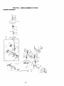
TO REPLACE
MOWER
BLADE
DRIVE
BELT (See Illustration Next Page)
The mower blade drive belt may be
replaced without tools. Park the tractor on
level surface. Engage parking brake.
BELT REMOVAL
-
• Remove mower from tractor (See "TO
REMOVE MOWER" in this section of
its highest position.
Check adjustment on right side of tractor.
Measure distance "D" directly in front and
behind the mandrel at bottom edge of
mower housing as shown.
• Before making any necessary adjustments, check that both front links are
this manual).
• Work belt off both mandrel pulleys
idler pulleys.
• Pull belt away from mower.
23
and
BELT INSTALLATION • Install new belt in reverse order of
removal.
• Make sure belt is in all pulley grooves
and inside all belt guides.
• Install mower in reverse order of
removal instructions.
Mandrel
Pulley
Idler
Pulleys
Mandrel
Pulley
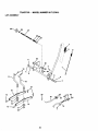
TO ADJUST BRAKE
Your tractor is equipped with an adjustable
brake system which is mounted on the
right side of the transaxle.
If tractor requires more than six (6) feet
stopping distance at high speed in highest gear, then brake must be adjusted.
• Depress clutch/brake pedal and engage
parking brake.
• Measure distance between brake operating arm and nut "A" on brake rod.
• If distance is other than 1-1/2", loosen
jam nut and turn nut "A" until distance
becomes 1-1/2". Retightenjam nut
against nut "A".
• Road test tractor for proper stopping
distance as stated above. Readjust if
necessary. If stopping distance is still
greater than six (6) feet in highest gear,
further maintenance is necessary.
Contactyour near_t
authorized service 5enter/department.
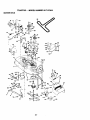
TO REPLACE
MOTION
• Remove mower (See "TO REMOVE
MOWER" in this section of this manual.)
• Remove belt from stationary idler and
clutching idler.
• Pull belt slack toward rear of tractor.
Remove belt upwards from transaxle
pulley by deflecting belt keepers.
• Pull belt toward front of tractor and
remove downwards from around engine
pulley.
• Install new belt by reversing above procedure.
Engine.
Pulley
Clutching
Idler
Stationary
Idler
Transaxle
Nut =A"
_Operating
BELT
Park the tractor on level surface. Engage
parking brake. For assistance, there is a
belt installation guide decal on bottom side
of left footrest.
With Parking Brak_Engaged"
/am
DRIVE
Pulley
Nut
Arm
24"
_=
TRANSAXLE
SHIFTER LINKAGE AND
ADJUSTMENT
The transaxle should be in neutral when
• Replace washers and snap retaining
ring securely in axle groove.
• Replace axle cover.
NOTE: To seal tire punctures and prevent
flat tires due to slow leaks, tire sealant
may be purchased from your local parts
dealer. Tire sealant also prevents tire dry
rot and corrosion.
the gear shift lever is in the neutral (N)
(lock gate) position. The adjustment is
preset at the factory; however, if adjustment is needed, proceed as follows:
• Make sure transaxle is in neutral (N).
• Loosen two Iocknuts on tie rod.
• Turn center rod until gearshift lever falls
into neutral lock gate on fender console.
• Tighten Iocknuts securely.
Washers
Retaining
Ring
I
Axle Cover
'_
Square Key
(Rear Wheel Only)
Locknuts
TO START
ENGINE
WITH
A WEAK
BATTERY
&,CAUTION:
Lead-acid batteries generate explosive gases. Keep sparks, flame
and smoking materials away from batteries. Always wear eye protection when
around batteries.
Rod
he
Transaxle
If your battery is too weak to start the
engine, it should be recharged. (See
"BATIERY"
in the MAINTANCE section of
this manual).
If =jumper cables" are used for emergency
starting, follow this procedure:
IMPORTANT:
Your tractor Is equipped
with a 12 volt negative grounded system.
The other vehicle must also be a 12 volt
TO ADJUST STEERING WHEEL ALIGNMENT
If steering wheel crossbars are not horizontal (left to fight) when wheels are positioned straight forward, remove steering
wheel and reassemble per instructions in
the Assembly section of this manual.
negative grounded system. Do not use
your tractor battery to start other vehicles.
TO AI-I'ACH
• Connect
FRONT WHEEL TOE-IN/CAMBER
The front wheel toe-in and camber are not
JUMPER
CABLES
-
each end of the RED cable to
the POSITIVE (+) terminal of each battery, taking care not to short against
chassis.
• Connect one end of the BLACK cable to
adjustable on your tracts. If_amage has
occurred to affect the front wheel toe-in or
camber, contact your nearest authorized
service center/department.
TO REMOVE WHEEL FOR REPAIRS
the NEGATIVE (-) terminal of fully
charged battery.
• Connect the other end of the BLACK
cable to good CHASSIS GROUND,
away from fuel tank and battery.
• Block up axle securely.
• Remove axle cover, retaining ring and
washers to allow wheel removal (rear
wheel contains a square key - Do not
lose).
• Repair tire and reassemble.
• On rear wheels only: align grooves in
rear wheel hub and axle. Insert square
key.
TO REMOVE
ORDER -
CABLES,
REVERSE
• BLACK cable first from chassis and
then from the fully charged battery.
• RED cable last from both batteries.
25
INTERLOCKS
._
"PosdJve
(+)
*
n
Negative
()-
L.H.P_anel_-_I
I
I
Bolt
REPLACING
TO REPLACE
FUSE
Replace with 30 amp automotive-type
plug-in fuse. The fuse holder is located
behind the dash.
BATTERY
ACAUTION:
Do not short batte_j terminals by allowing a wrench or any other
object to contact both terminals at the
same time. Before connecting battery,
remove metal bracelets, wristwatch
bands,rings, etc,
Positive terminal must be connected first
to prevent sparking from accidental
grounding.
• Lift
hood to raisedposition.
• Remove terminalguard.
• Disconnect BLACK battery cable then
RED battery cable and carefully remove
battery from tractor.
• Install new battery with terminals in
same position as old battery.
• Reinstall terminal guard•
• First connect RED battery cable to positive (+) battery terminal with hex bolt
and keps nut as shown: Tighten securely.
• Connect BLACK grounding cable to
negative (-) battery terminal with
remaining hex bolt and keps nut.
.Tighten securely.
• Close terminal access doors.
• Close hood.
TO REMOVE HOOD AND GRILL
ASSEMBLY
• Raise hood.
• Unsnap headlight wire connector.
• Stand in front of tractor. Grasp hood at
sides, tilt toward engine and lift off of
tractor.
• To replace, reverse above procedures.
..,i0.t
Connector
ENGINE
Maintenance, repair, or replacement of the
emission control devices and systems,
which are being done at the customers
expense, may be performed by any nonroad engine repair establishment or individual. Warranty repairs must be performed by an authorized engine manufacturer's service outlet.
TO ADJUST THROTTLE CONTROL
CABLE
Hex
The throttle control has been preset at the
factory and adjustment should not be necessary. Check adjustment as described
below before loosening cable. If adjustment is necessary, proceed as follows:
• With engine not running, move throttle
control lever to fast position.
• Check that swivel is against side of
quarter circle. If it is not, loosen cable
clamp screw and pull cable back until
swivel is against quarter circle. Tighten
cable clamp screw securely.
TO ADJUST CHOKE CONTROL
=ositive
'_Red)
Cable
Terminal
Guard
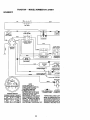
AND RELAYS
Loose or damaged wiring may cause your
tractor to run poorly, stop running, or prevent it from starting.
• Check wiring. See electrical wiring diagram in the Repair Parts section.
Negative
(Black) Cable
TO REPLACE HEADUGHT
BULB
• Raise hood.
• Pull bulb holder out of the hole in the
backside of the grill.
• Replace bulb in holder and push bulb
holder securely back into the hole in the
backside of the grill.
• Close hood.
The choke control has been preset at the
factory and adjustment should not be necessary. Check adjustment as described
26
then tum out (countemlockwise)1-1/4
to 1-1/2 turns.
belowbeforelooseningcable. If adjustmentis necessary,proceedas follows:
• With engine not running, move choke
control (located on dash panel) to full
choke position.
• Remove air cleaner cover, filter and cartridge plate to expose carburetor choke
(see =AIR FILTER" in the Maintenance
section of this manual).
• Choke should be closed. If it is not,
loosen casing clamp screw and move
choke cable until choke is completely
closed. Tighten casing clamp screw securely.
• Reassemble air cleaner.
FINAL SE'I-I'ING
-
• Start engine and allow to warm for five
minutes. Make final adjustments with
engine running and shift/motion control
lever in neutral (N) position.
• With throttle control lever in slow position, hold throttle lever against idle
speed screw and adjust idle speed
screw to obtain 1200 to 1400 RPM.
• While still holding throttle lever against
idle speed screw, tum idle mixture
screw in (clockwise) until engine begins
to die and then tum out (counterclockwise) until engine runs rough. Turn
screw to a point midway between those
two positions.
• Continue to hold throttle lever against
idle speed screw and adjust idle speed
screw to obtain 900 to 1200 RPM. Release throttle lever.
ACCELERATION
TEST -
• Move throttle control lever from slow to
Choke Closed_
Casing _
_
sCIcreanP_
TO ADJUST
_
Choke Lever
CARBURETOR
The carburetor has been preset at the factory and adjustment should not be necessary. However, minor adjustment may be
required to compensate for differences in
fuel, temperature, altitude or load. If the
carburetor does need adjustment, proceed
as follows:
In general, tuming the mixture screw in
(clockwise) decreases-,the_upply
of fuel to
the engine giving a leaner fuel/air mixture.
Turning the mixture screw out (counterclockwise) increases the supply of fuel to
the engine giving a richer fuel/air mixture.
IMPORTANT: Damage to the needles and
the seats in carburetor may result if screw
is turned in too tight.
PRELIMINARY
SETTING
fast position. If engine hesitates or dies,
tum idle mixture screw out (counterclockwise) 118 tum. Repeat test and
continue to adjust, if necessary, until
engine accelerates smoothly.
High speed stop is factory adjusted.
Do
not adjust - damage may result.
IMPORTANT:
Never tamper with the
engine govemor, which is factory set for
proper engine speed. Overspeeding the
engine above the factory high speed setting can be dangerous. If you think the
engine-governed high speed needs
adjusting, contact your nearest authorized
service center/department,
which has
proper equipment and experience to make
any necessary adjustments.
ldle Speed
rew
Idle Mixture
Screw
Throttle Lever
Idle Speed
-
• Be sure you have a clean air filter, and
the throttle control cable and choke are
- adjusted properly (see above).
• With engine off turn idle mixture screw
in (clockwise) closing it finger tight and
Screw
Throttle
Lever
27
Mixture
Screw
Immediately prepare your tractor for storage at the end of the season or if the tractor will not be used for 30 days or more.
_CAUTION:
Never store the tractor with
gasoline in the tank inside a building
where fumes may reach an open flame or
spark. Allow the engine to cool before storing in any enclosure.
TRACTOR
Remove mower from tractor for winter
storage. This will allow you to clean it thoroughly. Remove all dirt, grease, leaves,
etc. Store in a clean, dry area.
• Clean entire tractor (See =CLEANING" in
the Maintenance section of this manual).
• Inspect and replace belts, if necessary
(See belt replacement instructions in the
Service and Adjustments section of this
manual).
• Lubricate as shown in the Maintenance
section of this manual.
• Be sure that all nuts, bolts and screws
are securely fastened. Inspect moving
parts for damage, breakage and wear.
Replace if necessary.
• Touch up all rusted or chipped paint surfaces; sand lightly before painting.
BATTERY
• Fully charge the battery for storage.
• After a period of time in storage, battery
may require recharging.
• To help prevent corrosion and power
leakage during long periods of storage,
battery cables should be disconnected
and battery cleaned thoroughly (see "TO
CLEAN BATTERY AND TERMINALS" in
fuels (called gasohol or using ethanol or
methanol) can attract moisture which
leads to separation and formation of acids
during storage. Acidic gas can damage the
fuel system of an engine while in storage.
• Drain the fuel tank.
• Start the engine and let it run until the
fuel lines and carburetor are empty.
• Never use engine or carburetor cleaner
products in the fuel tank or permanent
damage may occur.
• Use fresh fuel next season.
NOTE: Fuel stabilizer is an acceptable
altemative in minimizing the formation of
fuel gum deposits during storage. Add stabilizer to gasoline in fuel tank or storage
container. Always follow the mix ratio
found on stabilizer container. Run engine
at least 10 minutes after adding stabilizer
to allow the stabilizer to roach the carburetor. Do not drain the gas tank and carburetor if using fuel stabilizer.
ENGINE
OIL
Drain oil (with engine warm) and replace
with clean engine oil. (See "ENGINE" in
the Maintenance section of this manual).
CYLINDER(S)
• Remove spark plug(s),
• Pour one ounce of oil through spark
plug hole(s) into cySnder(s).
• Turn ignition key to "START" position for
a few seconds to distribute oil.
• Replace with new spark plug(s).
OTHER
• Do not store gasoline from one season
to another.
the Maintenance sBction of'this manual).
• After cleaning, leave cables disconnected and place cables where they cannot
come in contact with b_ittew terminals.
• If battery is removed from tractor for
storage, do not store battery directly on
concrete or damp surfaces.
• Replace your gasoline can if it starts to
rust. Rust and/or dirt in your gasoline
will cause problems.
• If possible, store your tractor indoors
and cover it to give protection from dust
and dirt.
• Cover your tractor with a suitable protective cover that does not retain mois-
ENGINE
ture. Do not use plastic. Plastic cannot
breathe, which allows condensation to
form and cause your tractor to rust.
IMPORTANT:
Never cover tractor while
FUEL SYSTEM
IMPORTANT:
It is important to prevent
gum deposits from forming in essential fuel
system parts suqh as carburetor, fuel filter,
fuel hose, or tank during storage. Also,
experience indicates that alcohol blended
engine and exhaust areas are still warm.
28
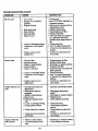
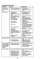
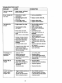
TROUBLESHOOTING
PROBLEM
Willnotstad
CHART
CAUSE
CORRECTION
• Out of fuel.
• Engine not"CHOKED"
properly.
• Engine flooded.
•
•
•
•
• Engine valves out of
adjustment.
•
•
•
•
•
•
•
•
•
•
Dirty air filter.
Bad spark plug.
Weak or dead battery.
Dirty fuel filter.
Stale or dirty fuel.
• Engine valves out of
adjustment.
• Clutch/brake pedal not
depressed.
• Attachment clutch is
engaged.
• Weak or dead battery.
• Blown fuse.
•_'Co_oded
battery terminals.
Clean/replace air filter.
Replace spark plug.
Recharge or replace battery.
Replace fuel filter.
Drain fuel tank and refill with
fresh gasoline.
• Check all wiring.
• See "To Adjust Carburetor"
in Service and Adjustments
section.
• Contact an authorized service center.
• Depress clutch/brake pedal.
• Disengage attachment
clutch.
• Recharge or replace battery.
• Replace fuse.
• Clean battery terminals.
• Loose or damaged wiring.
• Faulty ignition switch,
• Check all widng.
• Check/replace ignition
switch.
• Faulty solenoid or starter.
• Check/replace solenoid or
starter.
• Contact an authorized service center.
• Faulty operator presence
switchles ),
Engine clicks but
will not-start
attempting to start.
Replace spark plug.
Clean/replace air filter.
Replace fuel filter.
Drain fuel tank and carbure-
tor, refill tank with fresh
gasoline and replace fuel filter.
• Check all widng.
• See "To Adjust Carburetor"
in Service and Adjustments
section.
• Contact an authorized service center.
• - Loose or damaged wiring.
• Carburetor out of adjustment.
Engine will not turn
over
in
Operation section.
• Wait several minutes before
•
•
•
•
Bad spark plug.
Dirty air filter.
Dirty fuel filter.
Water in fuel.
• Loose or damaged wiring.
• Carburetor out of adjustment.
Hard to start
• Fill fuel tank.
• See =TO START ENGINE"
• Weak or dead battery.
• Corroded battery terminals.
29
• Recharge or replace battery.
• Clean battery terminals.
;ROUBLESHOOTING
PROBLEM
CHART
CAUSE
Engine clicks but
will not start (cont'd)
Loss of power
CORRECTION
• Loose or damaged wiring.
• Faulty solenoid or starter.
l • Cutting too much
grass/too fast.
• Throttle in =CHOKE" position,
• Build-up of grass, leaves
and trash under mower.
• Water in fuel.
fresh gasoline.
• Drain fuel tank and carbure-
• Dirty engine air
screen/fins.
• Dirty/clogged muffler.
• Loose or damaged wiring.
• . Carburetor out of adjustment.
• Engine valves out of
adjustment.
Engine continues to
run when operator
leaves seat with attachment clutch
• Clean underside of mower
• Dirty fuel filter.
• Stale or dirty fuel.
• Spark plug wire loose.
vibration
• Set in =Higher Cut" position/reduce speed.
• Adjust throttle control.
housing.
• Clean/replace air filter.
• Check oil level/change oil.
• Clean and regap or change
Spark plug.
• Replace fuel filter.
• Drain fuel tank and refill with
• Dirty air filter.
• Low •oil level/dirty oil.
• Faulty spark plug.
! Excessive
• Check all wiring.
• Check/replace
solenoid or
starter.
tor, refill tank with fresh gasoline and replace fuel filter.
• Connect and tighten spark
plug wire.
• Clean engine air screen/fins.
• Clean/replace muffler.
• Check all wiring.
• See "To Adjust Carburetor" in
Service and Adjustments
section.
• Contact an authorized service center.
• Worn, bent or loose blade.
• Replace blade. Tighten blade
bolt.
• Bent blade mandrel.
• Loose/damaged part(s).
• Replace blade mandrel.
• Tighten loose part(s).
Replace damaged parts.
• Faulty operator-safety
-=presence control system.
• Check wiring, switches and
connections. If not
corrected, contact an authorized service center.
• Worn,-bent or loose blade.
• Replace blade. Tighten blade
bolt.
• Level mower deck.
• Clean underside of mower
engaged
i Poor cut - uneven
• Mower deck not level.
• Buildup of grass, leaves,
and trash under mower.
• Bent blade mandrel.
• Clogged mower deck vent
holes from buildup of
30
housing.
• Replace blade mandrel.
• Clean around mandrels to
open vent holes.
F'ROUBLESHOOTING
CHART
PROBLEM
CAUSE
Poorcut -
uneven
grass, leaves, and trash
around mandrels.
(cont'd)
Mower blades will
not rotate
Poor grass discharge
CORRECTION
• Obstruction in clutch
mechanism.
• Remove obstruction.
• Worn/damaged
drive belt,
• Replace mower drive belt.
mower
• Frozen idler pulley.
• Frozen blade mandrel.
• Replace idler pulley.
• Replace blade mandrel.
• Engine speed too slow.
• Place throttle control in
=FAST" position.
• Shift to slower speed.
• Allow grass to dry before
mowing.
• Level mower deck.
• Travel speed too fast.
• Wet grass.
• Mower deck not level.
• Low/uneven tire air pressure.
• Worn, bent or loose blade.
• Buildup of grass, leaves
and trash under mower.
• Mower drive belt worn.
• Blades improperly
installed.
• Improper blades used.
• Clogged mower deck vent
holes from buildup of
grass, leaves, and trash
around mandrels.
Headlight(s) not
working (if so
equipped)
Battery will not
charge
Engine "backfires"
when turning
engine "OFF"
i•
•
•
•
•
• Check tires for proper air
pressure.
• Replace/sharpen blade.
Tighten blade bolt.
• Clean underside of mower
housing.
• Replace mower drive belt.
• Reinstall blades sharp edge
down.
• Replace with blades listed in
this manual.
• Clean around mandrels to
open vent holes.
Switch is"OFF".
• Turn switch =ON".
Bulb(s) burned out.
Faulty light switch.
Loose or damaged wiring.
Blown fuse.
•
•
•
•
Replace bulb(s).
Check/replace light switch.
Check wiring and connections.
Replace fuse.
• Bad battery cell(s).
% Poor cable connections.
• Faulty regulator (if so
equipped).
• Faulty alternator.
• Replace battery.
• Check/clean all connections.
• Engine throttle control not
set at =SLOW"
• Move throttle control to
position for 30 seconds
before stopping engine.
31
• Replace regulator.
• Replace alternator.
=SLOW" position and allow
to idle for 30 seconds before
stopping engine.
32
TRACTOR
- - MODEL NUMBER
917.270811
SCHEMATIC
°°
BATTERy
AMMETER
(OPTIONAL)
IGNITION
SWITCH
BLACK
(CLUTCH OF_
(OPTIONAL)
A
SL*CK
(_l
IGNITION
UNIT
_
_wI
J
GAP
SPARK
PLL
-(2 PLUGS (
TWIN CYL. FNC
BLUE
ORANGE
HEADLIGH"
IGNITION SWITCH
NOTE
YOUR TRACTOR IS
EQUIPPED WITH A SPECIAL
ALTERNATOR SYSTEM.
_ THE LIGHTS ARE NOT
"CONNECTED TO THE
NON-REMOVABLE
REMOVAl
BATTERY, BUT HAVE THEIR
CONNECTIONS
CONNECT]
OWN ELECTRICAL SOURCE.
BECAUSE OF THIS, THE
WIRING INSULATED CLIP_
BRIGHTNESS OF THE LIGHTS
WILL CHANGE WITH ENGINE
NOTE: IF WIRING INSULAT[
SPEED. AT IDLE THE LIGHTS
CLIPS WERE REMOVED FG
WILL DIM. AS THE ENGINE IS
SERVICING OF UNIT, THEY
SPEEDED UP, THE LIGHTS
SHOULD BE REPLACED TO
WILL BECOME THEIR BRIGHTEST. PROPERLY SECURE YOUR
33
TRACTOR - - MODEL NUMBER 917.270811
ELECTRICAL
i
\
+
29
28
I
34
TRACTOR
- - MODEL
NUMBER
917.27081i
ELECTRICAL
KEY
PART
NO.
NO.
1
2
8
10
11
12
16
19
20
21
22
24
25
26
27
28
29
30
31
32
33
40
41
42
43
44
45
52
55
70
NOTE:
163465
74760412
7603J
145211
150109
145769
153664
Std551125
73350400
147430
4152J
4799J
146148
108824X
73510400
145491
121305X
140301
124211X
141226
109310X
156442
71110408
131563
145673
73640400
121433X
141940
17490508
140413
DESCRIPTION
Battery 12 VOLT 26 AMP
Bolt Hex Hd 1/4-20unc x 3/4
Case Battery
Bolt,Btr Front 1/4-20 x 7-1/2
HolddownBattery Front Mount
Nut, Push NylonBatteryFront 1/4
Switch, InterlockPush-In
Washer Lock 1/4
NutJam Hex 1/4-20 Unc
Harness LightSocket(W/4152j)
Bulb Light#1156
Cable Battery
Cable Battery
Fuse
Nut Keps Hex 1/4-20 Unc
Cable Ground
Switch Seat
Switch Ign 4 Position
Nut Ignition
Cover IgnitionSwitch
Key Molded Craftsman
Harness Ign
Bolt BIk. F'_nHex 1/4-20 Unc x 1/2
Cover Terminal
Solenoid
Nut Keps BIkHex 1/4-20 Unc
Ammeter Rectangular6 Amp
ProtectionWire Loop
Screw Thdrol 5/16-18 x 1/2
Harness Engine B&S 14 OHV
All componentdimensionsgive in U.S. inches
1 inch = 25.4 mm
35
TRACTOR
- - MODEL
NUMBER
917.270811
CHASSIS AND ENCLOSURES
28
58
12
53
_p/S
S5
37
54
@_.3
-
115_"
3
142
,, _
36"
TRACTOR
- - MODEL
NUMBER
917.270811
CHASSIS AND ENCLOSURES
KEY
PART
NO.
NO.
1
2
3
4
5
9
10
11
12
13
14
17
18
20
23
25
26
28
29
30
31
37
38
39
51
52
53
54
55
57
58
60
64
74
114
115
116
140
142
143
144
145
NOTE:
16o392
140356
17490612
STD551025
155272
161917X013
STD533710
155927
145660
155936
17490608
144983X558
126938X
156437
124028)(
19131312
STD541437
145198)(558
155217X599
151287X558
139976
17490508
139886
139887
73800400
19091416
145201
161464
145202
STD522507
140547
STD533707
154798
STD541437
158112
17490620
19131614
158418
165867
1_496_
154207
156524
DESCRIPTION
Chassis Assembly
Drawbar
Scraw, Thd. Roll. 3/6-16x 1
Washer 13/32 x 3/4 x 16 Gauge
BumperHood/Dash
Dash
Bolt,Carriage 3/8-16 x 1
Panel, Dash, LH.
Clip "13nnerrnanGrilleP/L
Panel, Dash, R.H.
ScrawThdrol 3/8-16 x 1/2
HoodAssembly
Bumper Hood
Plate Mtg BatteryFuel Tank
Bushing,Snap, Nylon, Fuel Line
Washer 13/32 x 13/16 x 12 Gauge
Locknut,Hex, with Insert3/8-16 Une
Grillew/CUpsMS-558
Lens, Grille
Fend/Ftrest
Bracket,Fender Support
ScrawThdrol 5/16-18 x 1/2
Pivot BracketAssembly,L.H.
Pivot BracketAssembly,R.H.
Nut Lockw/Insert 1/4-20 UNC
Washer 9/32 x 7/8 x 16 Ga.
Bracket GrillePickoffLH
Screw Hex Wshd 8-18 x 7/8
Bracket Gdlle PickoffRH
Bolt,Fin Hex 1/4-20 UNC x .75
Air Duct P/L 18HP B&S Opp. Twin
Bolt Rdhd Sqnk 3/8-16 UNC x 3/4
Dash LowerSTLT
Nut Crownlock 3/8-16 UNC
Keeper Belt Rear Lh Stl
Screw Thrdol3/8-16 x 1-1/4
Washer 13/32 x I x 14 Ga.
BracketSuspensionFront
Plate ReinforcementSTLT
Bracket SwaybarChassis
Bracket Pnt FootrestSTLT
Rod PivotChassis/Hood
All componentdimensionsgive in U.S. inches
1 inch= 25.4 mm
37
TRACTOR
- - MODEL NUMBER
917.270811
GROUND DR:VE
57
72
116
1B
26
38
27
TRACTOR
- - MODEL
NUMBER
917.270811
GROUND DRIVE
KEY
NO.
1
PART
NO.
........
2
3
4
5
6
8
10
11
13
14
18
146682
123666X
12000028
121520X
17490512
154792
STD561210
105701X
74550412
STD551125
STD523710
"19
21
22
24
25
26
27
28
29
30
31
32
34
35
36
37
38
39
40
41
42
47
48
49
50
51
52
STD541437
106933X
130804
STD541237
106888X
STD551037
STD561210
145204
124236X
130807
127275X
STD523107
155071
120183X
STD551062
STD571810
131494
STD523727
4470J
165838
19131312
127783
154407
123205X
STD523715
STD541437
STD54143t
53
55
105710X
t 05709X
DESCRIPTION
KEY
NO.
Transaxte (See Breakdown)
Peerless 206-545C
Spring, Return, Brake
Pulley, Transaxle
Ring, Retainer
Strap, Torque
Screw, Thd., Roll. 5/16-18 x 3/4
Rod Shifter Fender STLT
Pin, Cotter
Washer, Shift Plate
Bolt 1/4-28 UNF W/Patch Gr. 8
Washer
Bolt Fin Hex 3/8-16 UNC x 1.
Gr 5
Nut
Knob
Rod, Brake
Nut
Spring, Brake Rod
Washer
Pin
Rod, ParkingBrake
Cap, ParkingBrake, Red
Bracket, Transaxle
Keeper, Belt,L.H.
Bolt
Shaft Assembly,Foot Pedal
Bearing, Nylon
Washer
Roll Pin
Pulley,idler, Flat
Bolt
Spacer, Split .395 x °59
Keepar, Bolt, Idler
Washer 13/32 x 13/16 x 12 Ca.
Pulley, Idler, V-Groove, PlasOc
BencrankClutch Grad Drv Stl
Retainer,Belt
Belt
Nut Crown Lock 3/8-16 UNC
Nut Crown Lock 5/16-18 UNC
56
57
58
59
61
62
63
64
65
66
70
72
74
75
76
77
78
79
80
81
82
83
84
85
86
87
88
89
90
96
112
113
116
145
148
149
150
151
Link,Cl_t ch__
Spring, Clutch Return
NOTE:
39
PART
NO.
DESCRIPTION
STD523712
130807
127274X
140312
17490612
8883R
140186
71170764
Bolt Fin Hex 3/8-16 x 1-1/4
V-Belt, Ground Drive
Keeper, Bolt, R.H.
Keeper, Belt, Center Span
Screw, Thd., Roll. 3/8-16 x 3/4
Cover, Pedal
Pulley, Engine
Bolt, Hex Head, Fin.
7/16-20 x 4 Grade 5
STD551143
Washer
154778
Keeper, Belt, Engine, FoolProof
134683
Guide, Mower Drive Belt, R.H.
19132012
Washer 13/32 x 1-1/4 x 12 Ca.
137057
Spacer, Axle
121749X
Washer 25/32 x 1-1/4 x 16 Ca.
STD581075
E-Ring
123583X
Key, Squara 2.0 x .1845/.1865
121748X
Washer 25/32 x 1-5/8 x 16
Gauge
STD580025
Key Woodruff
145090
Arm, Shift
161082
Sheft Assembly
123782X
Spring,Torsion
19171216
Washer 17/32 x 3/4 x 16 Ca.
145643
"ReRod
150360
Nut, Nylock
157480
Bushing
19212016
Washer
12000008
E-Ring
158391X428 Console,Shift, STLT
124346X
Nut, Self-'rhding,Wsh Hd 1/4
STD624003
RetainerSpring 1"
19091210
Washer 9/32 x 3/4 x 10 Gauge
127285X
StropTon:lue90 Degrees
72110610
Bolt Rdhd Sqneck 3/8-16 x 1.25
74490540
Bolt,Hex Flghd 5/16-18 Gr. 5
159103
Spacer
122052X
Spacer Retainer PM Mower
150935
BushingNylonCollered
19133210
Washer 13/32 x 2 x 10 Ca.
All componentdimensions give in U.S.
inches 1 inch = 25.4 mm
TRACTOR
- - MODEL
NUMBER
STEERING ASSEMBLY
,,_...... _..... ; _----,
-. -:_---?-:- .*
_41
i
T--'-'-'42
;
112
i
44
40"
917.270811
TRACTOR
STEERING ASSEMBLY
KEY
NO.
1
2
3
4
5
6
7
8
9
10
11
13
15
17
18
19
20
22
23
25
26
27
28
29
30
32
36
37
38
39
40
41
42
43
44
46
47
51
54
62
63
65
66
67
68
- - MODEL
PART
NO.
139768
154427
156483
157473
6266H
121748X
19272016
12000029
3366R
156438
STD551137
154779
73901000
156546
57079
124035X
126684X
71200410
127501
154406
126847X
136874
19131416
17490612
STD561210
130465
155099
152927
139769
19133808
STD541537
100711L
145054
121749X
153720
121232X
6855M
STD541431
74780520
156594
S_:D538710
154780
154404
74781044
154429
NUMBER
917.270811
DESCRIPTION
Staering Wheel
Axle AssemblySTMP DroppedSTL
SpindleAssembly, LH.
SpindleAssembly, R.H.
Bearing, Race, Thrust, Hardened
Washer 25/32 x 1-5/8 x 16 Gauge
Washer 27/32 x 1-1/4 x 16 Gauge
Ring, Klip
Bearing,Steering Column
DraglinkExtended Stamped
Washer, Lock
BearingAxle STLT/GT
Nut, Lock, Flange 5/8-11 UNC
ShaftAssembly, Steering
Washer, Thrust .515 x .750 x .033
Support,Shaft
Washer, Shim 1/4 x 5/8 x .062
Screw, Hex Socket 1/4-20x5/8
PittmanShaft Assembly
Bracket,Steering
Bushing,Link, Drag
Gear, Sector
Washer 13'32 x 7/8 x 16 Gauge
Screw, Thd., Roll. 3/8-16 x 3"4
Pin
Rod, "rie
Bushing,Steering
Screw
Insert, SteeringWheel
Washer 13/32 x 2-3/8 x 8 Gauge
Gripee Nut
Adaptor,SteeringWheel
Boot,Steering Shaft
Washer 25/32 x 1-1/4 x 16 Gauge
ExtensionShaft Steering LR.LT
Cap, Spindle
Fitting,Grease
Nut Lock Hex w/Ins. 5/16-18 UNC
BoltFin Hex 5/16-18 UNC x 1-1/4
Kit SteeringAsm Service
Bolt, Fin Hex 3/8-16 UNC x I Gr 5
Spacer Axle
Bearing Arm Pittman
Belt, Fin Hex 5/8-11 UNC x 2-3,4
Axle, Brace
NOTE: Allcomponentdimensionsgiven in U.S. inches
1 inch= 25.4 mm
41
TRACTOR - - MODEL NUMBER 917.270811
ENGINE
• 27
14
13
81
i
32
34
12 i
29
\
OPTIONAL
EQUIPMENT
Spark Arrester
.I
42
TRACTOR
MODEL NUMBER 917.270811
ENGINE
KEY
NO.
PART
NO.
1
2
3
4
5
6
7
8
10
11
12
13
14
15
16
17
23
25
26
27
29
31
32
33
34
35
37
38
39
81
162152
17720410
149723
144069
144068
138129
150176
145552
STD551125
STD522507
165287
13280336
13200300
STD551237
17490624
159880
145996
73920600
152927
137180
157103
161696
123487X
106082X
17490512
8543R
109227X
128861
DESCRIPTION
Control,Throt Paddle 32 22
Screw, Hex Thd Cut 1/4-20 x 5i8
Engine, B&S, (See Breakdown)No. 42E707-2631-El
MufflerExhaust
ExhaustAsm. Left
Exhaust Asm. Right
Clamp Tube Double Engine
Bolt 5/16-18unc x 3/4 W/Sems
Heat Shield Lt
Washer LockHvy. Helical 1/4
BoltFin Hex 1/4-20Unc x .75
Gasket, Muffler
Nipple, Pipe 4-1/2
Elbow,Standard 90°, 3/8-18 NPT
Washer Lock Ext Tooth3/8
Screw Thdrol3/8-16xl-1/2 Tytt
Shield, Bm/Dbr Guard
ControlChoke
Nut Keps3/8-24 Uo|
Screw"Fr #10-32 x 5 x 3/8 Flange
Arrestor,Spark
Tank, Fuel
Cap Fuel Guage
Clamp, Hose
Spacer Pad
Screw Thdrol 5/16-18 x 3-4 Tyt
Une, Fuel
Plug, Oil Drain(Order From Engine Manufacturer)
Pad Idler
Nut Flange 1/4-20 Starter Nut
NOTE: Allcomponentdimensionsgiven in U.S. inches
1 inch_=25.4 mm
43
TRACTOR
-- MODEL
NUMBER
917.270811
SEAT ASSEMBLY
KEY
NO.
1
2
3
4
5
6
7
8
9
10
11
12
PART
NO.
140123
140551
STD523710
19131610
145OO6
STD541437
124181X
17490616
19131614
155925
120068X
121246X
DESCRIPTION
Seat 33._) BIIdblkC raftsman
BracketPnt PivotSeat (blk)
BoltRn Hex 3/8-16onc X 1
Washer 13/32 X 3/4 X 10 Ga
Clip Push In Hinged
Nut Hex Lock w/Ins 3/8-16 Uric
Spdng Seat Cprsn 2 250 BIk71
ScrewThdrol 3/6-16 X 1Ty-tt
Washer 13/32 X 1X 14 Ga
Pan Pnt Seat (blk)
KnobSeat 1/2-13 Unc BIk
o BracketPnt MountingSwitch
KEY
PART
NO.
NO.
13
14
15
16
17
21
22
24
25
121248X
72050412
134300
121250X
123976X
153236
STD541431
19171912
127018X
DESCRIPTION
BOsh_gSnapBIkNytSOnd
BoltRdhd Sht Nk 1/4-20xl-1/2
Spacer Sp,t 28 X 96 Zinc
Spring Cprs_ 1 27 BIk Pnt
Nut Lock 1/4 Lge Fig Gr 5 Zinc
BoltShoulder5/16-18 Unc-2A
Nut Hex Lockw/Ins 5/16-18
Washer 17/32 X 1-3/16 X 12 Ga.
BoltShoulder5/16-18 X 62
NOTE: Allcomponent dimensionsgiven in U.S. inchesl inch = 25.4 mm
4
*
TRACTOR
- - MODEL
NUMBER
917.270811
DECALS
6
3
11
19 22
13
5
2
KEY
NO.
PART
NO.
1
2
3
4
5
156439
165392
163200
163202
163207
6
7
133644
163259
9
11
163204
156368
WHEELS
KEY
NO.
DESCRIPTION
Decal, Fender Danger Sears
Decal, Engine B&S
Decal, Hood, R.H. Craftsman
Decal, Hood, L.H. Craftsman
Decal, Fender_SD.Wl-d.
Rad/6Sp 42"
Decal, Maintenance
Decal, Panel Dash B&S 19.5
Turbo
Decal, Fender, Craftsman Gold
Decal, Fender STLT Oper Inst
FJS
& TIRES
PART
NO.
13
15
19
20
146046
160396
138047
163203
22
------
149516
138311
154515
154516
167659
167660
KEY
NO.
PART
NO.
I
2
3
4
59192
65139
106222)(
59904
DESCRIPTION
Decal, V-Belt Dr Sch Tractor
Decal, Mower Ddve Schemat{c
Decal, BatteryDiehard Seare
Decal, Deck Mower E.Z3
Mulching
Decal, Battery
Decal, LiftHandle
Pad Footrest LH STLT
Pad FootrestRH STLT
Owner's Manual, English
Owner's Manual, Spanish
DESCRIPTION
Valve Cap, "l]m
Stem, Valve
]]re, Front
Tube, Front'nre
(Not Provided,Sewice Item
Only)
4,10
6
106732X427
278H
7
9040H
5
11
8
9
10
106108X427
122082)(
7152J
11
- -
104757)(
144334
Rim, Front
Fitting,Grease (Front Wheel
Only)
Beadng, Flange (Front Wheal
Only)
Rim, Rear
"i]re,Rear
Tube, Rear'l]m
(Not Provided, Service Item
Only)
Cap, Axle
Sealant, "i]re10 oz.
NOTE: All componentdimensions given in U.S. inches
1 inch= 25.4 mm
45
TRACTOR
- - MODEL
NUMBER
917.270811
LIFT ASSEMBLY
27
23
7
49
30
3
13
26
46
6
4
13
19
20
13
19
15
31
32
46
TRACTOR
- - MODEL
NUMBER
917.270811
LIFT ASSEMBLY
KEY
NO,
1
2
3
4
5
6
7
8
11
12
13
15
16
17
18
19
20
23
24
25
26
27
28
29
30
31
32
49
50
PART
NO.
159460
159471
105767X
12000002
19211621
120183X
125631X
122365X
139865
139866
STD624008
127218
73350800
130171
73680800
139868
163552
110807X
19131016
2876H
76020308
126971X
73350600
138057
150233
140302
73540600
145212
110452X
DESCRIPTION
LiftLever Inner WireAssembly
Shaft Assembly,Lift
Pin, Groove
E-Ring
Washer 21/32 x 1 x21 Gauge
Bearing, Nylon
Grip, Handle, Ruted
Button,Plunger, Red
Link, Lift,L.H.
Link, Lift,R.H.
Retainer Spdng
Link, Front
Nut, Hex, Jam 1/2-13 UNC
Trunnion
Nut Lock 1/2-13 UNC
Arm,Suspension. Rear
Retainer Spdng
Nut, Special
Washer 13/32 x 5/8 x 16 Gauge
Spdng
Pin, Cotter 3/32 x 1/2
Red, Adjust, Lift
Nut, Hex, Jam 3/8-16 UNC
Knob, Inf. 3/8-16
Trunnion,Inf Height
Bearing, Pvt, Lift Special
Nut, Cmwnlock 3/8-24
Nut Flange Lock
Nut Push Phos & Oil
NOTE: All component dimensionsgiven in U.S. Inches
1 inch= 25.4 mm
47
TRACTOR
- - MODEL NUMBER
917.270811
MOWER DECK
103 1
106
lOl
lOZ/
21
116
113\ 111, .L...114
_22324
25
16
28
"27
4
6
19_
J
21
48"
TRACTOR
- - MODEL
NUMBER
917.270811
MOWER DECK
KEY
NO.
PART
NO.
1
2
3
164961
STD533107
138017
4
5
6
8
138440
STD624008
130832
850857
9
10
11
12
13
STD551137
140296
134149
129895
137645
14
15
16
17
18
19
20
21
22
23
24
25
26
27
28
128774
110485X
140329
72110610
72140505
132827
159770
STD541431
134753
131267
105304X
123713X
110452X
130968
19111016
29
30
31
32
33
34
35
36
37
131491
157722
129963
153535
137266
STD533717
133835
131494
STD551037
40
41
43
STD541437
133551
140083
44
45
46
48
49
50
51
140088
STD624003
137729
133944
155066
131340
STD541410
52
53
54
55
139888
131845
133943
155046
DESCRIPTION
KEY
NO.
PART
NO.
56
58
59
67
68
71
72
73
74
122052X
140086
141043
162113
144200
142427
131870
127847
121748)(
75
76
12000029
128903
77
78
127845
160570
Mower Deck Assembly,42"
Bolt
BracketAssembly,SwayBar,
Front
BracketAssembly,Sway Bar
Retainer Spring
Arm, Suspension,Rear
Bolt, Hex 3/8-24 x 1.25
Grade 8
Washer, Lock
Washer, Hardened
Blade, Mulching
Beadng, Ball
Shaft Assembly,Mandrel,
Vented (Includes Key
Number 12)
Housing,Mandrel, Vented
Boaring, Ball, Mandrel
Stripper,Vented Mower Deck
Bolt, Carriage 3/8-16 x 1-1/4
Bolt, Carriage 5/16-18 x 5/8
Bolt, Shoulder
Baffle, Vortex
NutCrownlock 5/16-18 UNC
Stiffener Bracket
Bracket,Deflector
Cap, Sleeve
Spdng, Torsion,Deflector
Nut, Push
Shield, Deflect-or
Washer 11/32 x 5/8 x 16
Gauge
ROd, Hinge
Screw Thdrol Washer Head
Washer, Spacer
Pulley, Mandrel
Nut, Toplock, Flanged
Bolt
Fastner, ChristmasTree
Pulley,Idler, Flat
Washer 13/32 x 13/16 x 16
Gauge
Nut Crownlock3/8-16 UNC
Rod, Pivot,with Nibs
Rod, Clu_h, Secondary, with
Nibs
Guard, Mandrel, LH.
Retainer
Screw, Thd. Roll 1/4o20 x 5/8
Washer, Hardened
RollerAssembly,Cam Follower
Bolt, Shoulder #10-24 Grade 5
Locknut
Bolt, Shoulder 5/16-18 UNC
Arm Assembly,Pad, Brake
Washer, Hardened
Arm, idler
79
80
81
82
83
84
85
92
101
102
103
104
105
106
111
112
113
114
115
116
117
118
119
121
128
129
130
127498
153701
73350600
142028
120958X
156084
72140620
STD541437
136420
71161010
19061216
STD551110
160793
2029J
155197
155198
17490512
STD541431
72110504
137644
133957
73930600
STD551037
143723
153390
19131312
STD523710
131
STD533710
132
19132203
141
--
6266H
130794
--
164963
DESCRIPTION
Spacer, Retainer
Spring,TorsionBrakes
Guard, TUV rdler
Knob Custom Oval
V-Bolt
Rod, Clutch, Pdmafy, with Nibe
Spring,Retum
Arm, Clutch, SecondaP/
Washer 25/32 x 1-5/8 x 16
Gauge
Ring, Klip
Bolt, Shoulder 3/8-16 UNC x
1.44
Keeper, Spring
Lever Asm. Clutch Pd Flm
STLT
Bushing,Large, Brass
Spring,Mower Clutch
Nut, Hex Jam 3/8-16 Unc
Trunnion,Adj.
Washer Sintered
Keeper Belt Idler
BoltCarriage 3/8-16 x 2-1/2
Nut
Mulcher Cover
Screw
Washer #10
Washer, Lock
LatchAssembly, Bagger
Nut, Weld
Bracket,Gauge, Wheel L.H.
Bracket,Gauge, Wheel R.H.
ScrawThdml 5/16-18x3/4
Nut, Hex, Keps 5/16-18 UNC
Bolt,Carriage 5/16 UNC x 1/2
Bolt, Shoulder
Wheel, Gauge
Nut, Centerlock3/8-16
Washer 3/8 x 7/8 x 14 Gauge
Bracket
Washer Felt
Washer 13/32 x 13/16 x 12 Ga.
Bolt, Fin Hex 3/8-16 UNC x 1
Gr. 5
Bolt, RDHD SQNK 3/8-16 UNC
x1
Spacer Washer 13/32 I.D. x 13/80.D, x 1/4
Washer Thrust .75 x 1.230
MandrelAssembly (Includes
Key Numbers8-10, 12-15, 31
and 32)
Mower Deck, Complete
(Standard Deck, Order
Separately Mulcher Plate and
Gauge Wheel Components,
Key Nos. 101-106 and 111-121) "
NOTE: Allcomponentdimensionsgiven in U.S.inches
1 inch= 25.4 rnm
49
TRACTOR
- - MODEL
PEERLESS TRANSAXLE-MODEL
@_
_--2
•
+7
917.270811
NUMBER 206-545C
71B
_
/q&6/_
NUMBER
o+-29
s
11
5O
TRACTOR
- - MODEL
PEERLESS TRANSAXLE-MODEL
REF
PART
NO.
NO.
1
2
3
4
5
6
6A
7
8
8A
9
10
11
12
13
772147
780086A
770128
776395
776409
778364
778369
778330
792180
792047
784352
784378
778334
778309
778368
14
778368
15
17
18
20
21
22
25
25A
26
27
28
29
29A
29B
29C
30
31
778370
786188
786102
792077A
792078
792079
792073A
792177
792125
792035
788040
780072
780160
780051
780199
780108
780001
31A
32
34
35
35A
36
37
38
39
40
780195
788083
780194
780193
780197
790075
790007
799021
786026
792076A
NUMBER
917.270811
NUMBER 206-545C
REF
PART
DESCRIPTION
NO.
NO.
Transaxle Cover
Needle Bearing 5/8"
Transexle Case
Countershaft
Output Shaft
Spur Gear (38 teeth)
Spur Gear (15 teeth)
Spur Gear (11 teeth)
Shift Key
Woodruff Key #9
Shift Collar
Shift Rod & Fork
Bevel Gear (30 teeth)
Input Bevel Pinion (13 teeth)
Bevel Gear (13 teeth) (Include.
14)
Bevel Pinion(13 teeth)
(Include. 13)
Ring Gear (43 teeth)
Drive Pin
Spacer 1.130 X .695
Ball 5/16" die
Set Screw 3/8 - 16 x 3/8"
Spring .310 OD x .625 L
Screw 1/4 - 20 x 1-1/4"
Screw 1/4-20 x 1-3/8"
Retaining Ring (pkg of 2)
Retaining Ring
Retaining Ring
Thrust Washer .627 ID x .031W
Thrust Washer .762 ID x .031W
Thrust Washer .762 ID x .031W
A_i-Rotation Washer .632
Cup Washer 1.127 ID x .032W
FlatWasher.750 ID x .056W
(Use As Needed)
FlatWasher .750 ID x .062W
Oil Seal 5/8"
Bushing .563
Ranged Bushing5 / 8" ID
Ranged Bushing .751
Brake _
_=_
Brake Pad Plate
Brake Pad (pkg of 2)
Dowel Pin
FlatWasher .312 ID x o059W
41A
42
42A
43
44
45
46
47
48
49
50
51
52
53
54
56
57
58
59
60
61
65
66
67
69
70
71
71B
76
77
79
82
790079
792073A
792085A
792075
790025
786066
786086
774690
774691
778356
778338
778354
778352
778350
778346
778355
778,337
778353
778351
778349
778345
780189
776422
776396
792170
786187
788069
788092
780090
788078A
792144
778333
83
85
87
150
157
180
900
778338
792154
788089A
788093A
788088A
730229A
794712
DESCRIPTION
Brake Lever
Screw 1/4- 20 x 1-1/4"
Screw 1/4- 20 x 2 1/4"
Locknut5 / 16- 24
BrakePad Holder
Spacer .2625 x 1.0
BrakeLever Bracket
AxJe(11-15/16" Long)
Axle (16 - 1 / 2"long)
SpurGear (29 teeth)
SpurGear (27 teeth)
SpurGear (23 teeth)
SpurGear (19 teeth)
SpurGear (16 teeth)
SpurGear (15 teeth)
Spur Gear (11 teeth)
Spur Gear (13 teeth)
Spur Gear (17 teeth)
Spur Gear (21 teeth)
Spur Gear (24 teeth)
Spur Gear (25 teeth)
FlatWasher .563 ID x .062W
InputShaft
Shifter& BrakeShaft
RetainingRing
Spacer .890
Square Cut Ring
"O" Ring
FlatWasher 1.128 ID x .058W
Inverted RetainingRing
Spring.430 OD x .5000 L
Bevel & SpurGear (30 & 13
teeth)
Spur Gear (27 teeth)
Oil FillPlug
Oil Seal 9/16"
LiquidGasket RTV Silicone
Oil Seal 3/4"
Gear Oil 80W90
ReplacementMST- 206-545C
Transaxle
NOTE: Allcomponentdimensionsgiven in U.S, inches
1 inch= 25.4 mm
51
TRACTOR
- - MODEL
NUMBER
917.270811
BRIGGS & STRATTON ENGINE-MODEL NUMBER 42E707, TYPE NUMBER 2631-E1
819
534
_
_'
642
165
643
535
52"
TRACTOR
- - MODEL
BRIGGS & STRATTON ENGINE-MODEL
NUMBER
917.270811
NUMBER 42E707, TYPE NUMBER 2631-E1
1358 GASKET SET J
51
1861 PUMP REPAIR KIT]
1121 CARBURETORKrrJ
•
I'la'M_I -- /
468
.- ._
_332
_
75
1005
53
51A
51
52
TRACTOR
-- MODEL
NUMBER
917.270811
BRIGGS & STRATTON ENGINE-MODEL NUMBER 42E707, TYPE NUMBER 2631-E1
801
783
802
615A
653
544
54
TRACTOR -- MODEL NUMBER 917.270811
BRIGGS& STRATTONENGINE-MODELNUMBER42E707,TYPE NUMBER2631-E1
3
_
22
881
244
5A
13
[ 1019 LABEL Krl1
REQUIRES SPECIAL TOOLS
TO INSTALL. SEE REPAIR
INSTRUCTION MANUAL.
305
308
306
307
55
TRACTOR
- - MODEL NUMBER
917.270811
BRIGGS & STRATTON ENGINE-MODEL NUMBER 42E707, TYPE NUMBER 2631-E1
KEY
NO.
PART
NO.
t
2
3
4
5
5A
7
7A
8
8A
497074
399265
391086
493304
493457
493458
271867
271868
495754
222892
9
10
10A
11
12
27803
94382
94830
280225
273208
271188
271189
94565
94239
394028
94196
399264
291675
94724
491180
222698
498584
498585
13
16
15
19
20
22
23
24
25
DESCRIPTION
•
•
•
•
•
•
•
•
Flywheel
.Key, Fiywheol
PistonAssembly,Standard Size
PistonAssembly,.010"
Oversize
PistonAssembly,.020"
Oversize
PistonAssembly,.030"
Oversize
Ring Set, StandardSize
Ring Set, .010"Oversize
Ring Set, .020" Oversize
Rin_,,Set,.030"Oversize
LocR,PistonPin
Pin, Piston,Standard Size
Pin, Piston, .005"Oversize
Red, Co'_hea_g, Standard
Size
Rod, Connecting,.020"
Undersize
Screw, ConnectingRod
_8588
498587
26
27
28
29
394959
39496O
394961
394962
263129
498319
391286
394306
397158
32
94671
33
34
35
390420
261528
65906
36
40
41
26828
221596
292260
42
45
46
50
51
51A
494553
261368
214484
213290
271412
281412
CylinderAssembly
Bushing
Seal, Oil
Sump, Engine
Head, Cyneder #1
Head, Cylinder#2
Gasket, CylinderHead #1
Gasket, Cylinder Head #2
Breather Assembly#1
Cover. Breather Cylinder#2
(Used Only on Kay #572,
Air Baffle withHdies for
Mounting)
Gasket, Breather
Screw, Seres
Screw, Sems
Tube, Breather
GaskeLCrankease,.O15"Thick
Gasket, Crankcase, .005" Thick
Gasket, Crankcase, .009_Thick
Screw, CylinderHead
Plug,Oil Drain
Crankshaft
"RmfngGear Key
Bushing
Seal, Oil
Screw, Seres
KEY
NO.
PART
NO.
52
270884
53
93970
54
75
78
91
95
96
97
98
99
102
103
104
195
107
108
109
116
117
93208
222511
95039
499281
93499
221939
499172
91920
26157
271607
298514
231435
394682
499655
225373
392673
280474
232018
232022
119
121
125
94152
491539
19306
127
147
161
165
187
223472
497684
496599
94289
299146
188
201
202
203
205
206
207
209
209A
219
219A
220
222
224
94627
262683
262684
280997
93971
94298
262337
262352
261563
394348
393415
222773
491282
94297
Valve, Exhaust
Valve, Intake
* Gasket, Intake Manifold
Mounting
Screw, Hex Head,
Carburetorto Manifold
Screw, Phillips
Washer, Spdng
Screw, Hex
Body Assembly,Upper
Screw, Seres
Valve, Throttle
Shaft,Throttle
Screw, FiUistarHead
Spring,Throttle Adjust
** Gasket, CarburetorBody
Float, Carburetor
** Pin, Reat Hinge
"* Valve, Needle
BodyAssembly,Lower
Valve, Choke
Shaft,Choke
* O-Ring
Jet, Needle Valve, Fixed
Jet, Needle Valve, Fixed,
HighAltitude
Screw, HexHead
CarburetorKit
Carburetor
•* Plug, Welch
Jet, Pilot
Base, Air Cleaner
Nut, Wing
Une, Fuel, 28" Long (Cut to
Suit)
Screw
Link
Link
Crank, Bell
Screw, Hex Head
Nut
Spring,Control, Red
Spring,Governor
Spdng, GovernorIdle
Gear, Governor
Oil Slinger
Washer, Thrust
Bracket,Control
Screw, Ton("
Includedin Gasket Set (495868)
Spring,Valve, intake
Spring,Valve, Exhaust
""
Includedin Carburetor Kit(491539)
Retainer,Valve, Intake
Retainer,Valve, Exhaust
"Keeper, Valve
"**
Includedin CarburetorKit (491539),
and Pump Repair Kit (393397)
Tappet, Valve
Gear, Cam
Manifold, Intake
....
DESCRIPTION
Gasket, CarburetorMounting
Spacer, Carburetor
....
56
Includedin Gasket Set (495868),
and CarburetorKit (491539)
NOTE: All componentdimensionsgiven in U.S. inches
"
1 inch=25;4,mm
TRACTOR
- - MODEL
BRIGGS & STRATTON ENGINE-MODEL
KEY
NO.
PART
NO.
227
229
491297
62199
230
235
240
244
257
284
284A
304
305
306
306A
307
308
308A
309
310
311
332
333
334
337
356
338
363
383
391
392
394
414
422
432
434
435
445
468
474
482
510
523
524
525
528
534
535
537
544
552
552A
538
562
567
223882
224995
394338
230318
93897
94674
94882
495469
94786
222846
223734
94930
224774
224775
497596
94003
497608
230674
394891
94731
802592
494705
495838
19203
89838
280197
261395
272638
220680
222875
221377
223688
93829
394019
497908
393474
93621
497606
494947
271157
495348
393815
94823
272490
271411
497603
262332
262331
93585
93853
94811
569
272645
NUMBER
917.270811
NUMBER 42E707, TYPE NUMBER 2631-E1
DESCRIPTION
KEY
NO.
PART
NO.
572
573
224816
491304
592
601
615
615A
616
634
634A
635
642
643
653
726
92278
93053
94298
263080
491530
271013
491287
66538
225008
496700
93585
391362
LeverAssembly, Governor
Washer
Washer, (_pvernorCrank, Inside
Shield, Fuel Spray
Filter, Fue_
Connector,Fuel Line
Screw, Seres
Screw, Hex Head
Screw, Hex Head
Housing,Blower, Red
Screw, Same
Shield, Cylinder
Shield, Cylinder
Screw, Self.Tapping
Cover, Air Guide
Cover, Air Guide
Motor,Starter
Bolt,Thru
Brash Set
Nut, Hax
Armature, Magneto
Screw, Sems
Plug, Spark
Wire, Stop
Gasket Sat
FlywheetPuller
Wrench, Spark Plug
Body,Pump
"* Spdng, Diaphragm
**" Diaphragm, Carburetor
Washer
Bracket,Oil Fill
*** Cap, Spdng
Cover, Diaphragm
Screw, Diaphragm Cover
Filter,Air
Screen, Rotating
Alternator
Screw,
Ddve, Starter
Cap, Oil RII
° Seal, FillTube
Tube, Oil RII (IncludesSeals
Hose, Vacuum
Screw,Air Cleaner
Filter,Air
.... Gasket,/_r Cleaner
Annatul'_ Starter
Lower Bushing,Governor
Upper Bushing,Governor
Screw, Hex Head
Bolt, Governor Lever
Screw, Hsx Head,
Back Plata to Cylinder
* Gasket, Base
741
783
801
802
803
819
842
847
851
858
859
860
861
868
869
870
871
877
881
955
1005
1006
1019
1090
2500
- -
DESCRIPTION
Baffle,Air,Cylinder#2
Plate, Back
Nut, Hex.
Clamp, Hose
Retainer, E-Ring
Retainer
Crank, Governor
°* Washer, Throttia Shaft
" Seal, Govsmor Shaft
Boot, Spark Plug
Cover, Air Cleaner
Plate,Air Cleaner
Screw, Hex Head
Gear, Ring
(Includes MountingParts)
262989
Gear, Timing
280104
Gear, Starter
394860
Cap, Ddve
497607
Cap, End
497604
Housing, Starter
94675
Screw, Hex Head
270920
* Seal, Cap
495715
Tube Assembly,Oil
493880
Terminal, Cable
270989
*** Diaphragm, Carburetor
271025
**" Gasket, Pump
261358
*" Spdng, Diaphragm
393397
RspairKit, Pump
497212
Seal, Valve
261463
Seat, Valve, Intake
213316
Seat, Valve, Exhaust
261961
Bushing,Guide (Exhaust Only)
231218
Bushing,Guide (intake, Brass)
393456
Wire, Alternator
495901
Plate, Cover
397882
Plugand Seat, Solenoid
281053
Fan, Rywheel
224901
Retainer,Fan
496726
Label Kit
97605
Retainer,Brush
42E707-2631 Replacement Engine
498543
Replacement Shortblock
Included in Gasket Bet (495868)
*"
Included in CarburetorKit (491539)
***
Includedin CarburetorKit (491539),
and Pump Repair Kit (393397}
....
included in Gasket Set (495868),
and CarburetorKit (491539)
NOTE: Alt component dimensionsgiven in U.S. inches
1 inch= 25.4 mm
57
58
SUGGESTED
GUIDE FOR SIGHTING SLOPES FOR SAFE OPERATION
ONLY RIDE UP AND DOWN HILL,
NOT ACROSS HILL
SIGHTING
GUIDE
_. ._.CuT
TH.i8
(O
!
Operate your Tractor up and down the face of slopes (not I
greater than 15°), never across the face. Make turns gradually to prevent tipping or loss of control. Exercise extreme
caution when changing direction on slopes.
I
For the repair or replacement parts you need
delivered directly to your home
Call 7 am - 7 pm, 7 days a week
1-800-366-PART
(1-800-366-7278)
Para ordenar piezas con entrega
domicilio - 1-800-659-7084
a
For in-house major brand repair service
Call 24 hours a day, 7 days a week
1-800-4-REPAIR
(1-800-473-7274)
Para pedir servicio de reparaci6n
domicilio - 1-800-676-5811
a
For the location of a Sears Parts and
Repair Center in your area
Call 24 hours a day, 7 days a week
1-800-488-1222
Imimim
mmmmm|
For information on purchasing a Sears
Maintenance Agreement or to inquire
about an existing Agreement
Call 9 am - 5 pm, Monday-Saturday
1-800-827-6655
When requesting ser_ce_>r ordering
parts, always provide the following
information:
• Product Type
• Model Number
• Part Number
• Part Description-
SE ARS
Arnenca's Repair Specialists
167659
10.29.98
RD
Printed in U.S.A.