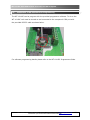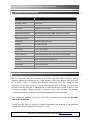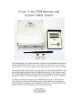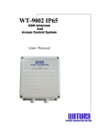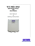
1
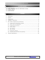
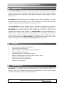
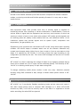
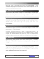
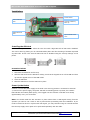
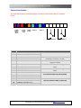
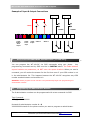
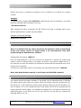
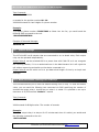
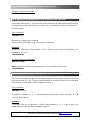
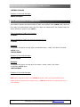
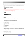
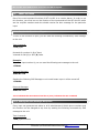
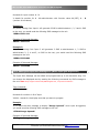
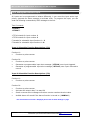
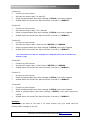
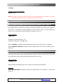
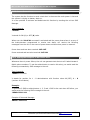
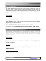
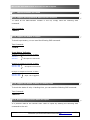
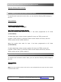
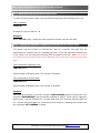
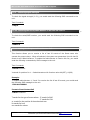
WT-1011RC IP65 G GS SM MR Re em mo otte eC Co on nttrro olllle err A An nd d A em m Alla arrm mS Sy ysstte User Manual & Setting Instructions W R R R W T U A C O P O A T O N S D N B H D WIIIT TU UR RA AC CO OR RP PO OR RA AT TIIIO ON NS SD DN NB BH HD D WT-1011RC IP65 GSM Remote Controller And Alarm System PACKAGE CONTENTS 1) 2) 3) 4) 1 1 1 1 pc pc pc pc IP65 Enclosure WT-1011RC Main Board with GSM Module mounted Battery Backup GSM Antenna CONTENTS 1. Introduction………………………………………………………………………………………………………………3 2. Features………………………………………………………………………………………………………………………3 3. Characteristic……………………………………………………………………………………………………………3 4. Installation Instructions………………………………………………………………………………………………6 5. WT-1011RC Programming Instructions ……………………………………………………………9 6. 5.1 Programming the Administrator Numbers ……………………………………………………………………9 5.2 Access Control for Administrator……………………………………………………………………………………10 5.3 Programming the Guest List………………………………………………………………………………………..…10 5.4 Output Settings………………………………………………………………………………………………………………11 5.5 Input Settings…………………………………………………………………………………………………………………15 5.6 Alarm Settings………………………………………………………………………………………………………………20 5.7 Miscellaneous Settings…………………………………………………………………………………………………23 5.8 Connection of RS-232 Cable for Programming………………………………………………………………28 Technical Specifications……………………………………………………………………………….……………29 WT-1011RC IP65 – USER MANUAL – Rev.1.6 – Technical Support: [email protected] COPYRIGHT ©2010 WITURA CORPORATION SDN BHD 2 WT-1011RC IP65 GSM Remote Controller And Alarm System 1. INTRODUCTION WITURA WT-1011RC GSM Remote Controller and Alarm System allow you to use your mobile phone to monitor and control your business from any location. Its alarm facilities provide a flexible way to distribute critical alarm information to any number of mobile phone users. WT-1011RC provides detailed alarm messages, secure alarm acceptance, full alarm reporting and even remote process control. This allows user to rectify problems directly via their mobile phone within minutes of the alarm occurring. The WT-1011RC can monitor 2 digital inputs. A SMS alarm message can be sent when inputs triggered. The user can also interrogate the inputs through SMS messaging. The WT-1011RC also has 2 heavy-duty relay outputs can be used to switch on any application like lamps, pumps, heaters etc. Output Relay 1 can be switched ON for a preset time by calling its cell phone number, there is no call charges incurred when dialing the unit as it will recognize an authorized telephone number calling it and reject the call without answering. Output Relay 2 can be programmed to switch on for a predetermined length of time by sending the WT-1011RC a text command. 2. FEATURES More flexible than pager based systems Low set up and running costs Faster response to alarms and process disturbances Allows reduced manning levels Increased freedom of movements for users Reduces wasted traveling time responding to alarm events Provides more detailed information Easier monitoring of remote process Allows full remote control 3. CHARACTERISTIC WT-1011RC is a versatile SMS alert device suited for most monitoring needs. It is simple to use yet is packed with powerful functionalities to meet a wide ranging industrial and commercial and residential applications WT-1011RC IP65 – USER MANUAL – Rev.1.6 – Technical Support: [email protected] COPYRIGHT ©2010 WITURA CORPORATION SDN BHD 3 WT-1011RC IP65 GSM Remote Controller And Alarm System 3.1 Standalone Operation Housed in the weather and desk proof IP65 enclosure complete with internal industrial modem, monitoring controller and flexible operating firmware. It is very easy to setup, install and use. 3.2 2 Digital Inputs Most equipment today does provide some form of alerting signal to interface to monitoring devices from reporting of various malfunction or abnormalities. There are various kinds of signal that the equipment can send out, most common of which are opening or closure of one or more switch relay contact. UPS usually provide signals such as incoming power fail, battery mode, battery level low, and switchover failure. An air conditioner system may provide signals such as system on/off, compressor over temperature, low gas pressure, etc. Equipments to be monitored are connected to WT-1011RC using these alarm signaling contacts. WT-1011RC keeps a constant watch over all the contacts. Whenever any contact input changes status (either from a close to open or from an open state to close state) it is captured by WT-1011RC. It will then process the input according to the configuration provided by the user. The correct SMS messages will be sent to 8 mobile phone users. WT-1011RC is so fast in capturing the change of status of any signaling contacts that no event will be missed out up to 2 inputs can be monitored directly. The flexibility of WT1011RC is in allowing remote query of input status using SMS. To change contacting mobile phone number is also very easy. Authorize personal remotely using SMS command to add, change or delete mobile phone number in WT1011RC. 3.3 2 Digital Outputs WT-1011RC is a 2 way device. Besides monitoring inputs and act upon such inputs it also allow mobile phone users to compose SMS messages to it. When WT-1011RC receives any SMS, it will look its memory bank to see what it is supposed to do and action according. No action SMS are ignored. WT-1011RC IP65 – USER MANUAL – Rev.1.6 – Technical Support: [email protected] COPYRIGHT ©2010 WITURA CORPORATION SDN BHD 4 WT-1011RC IP65 GSM Remote Controller And Alarm System Relay 1 can turned on for a preset time by calling its number and Relay 2 can be activated by text messages from mobile phone. Creating action messages are done with the same ease as that of input monitoring. 3.4 Querying Inputs And Outputs Status Authorized groups can also query the status of an input or output. This is very useful feature to determine the present status of an input or output. The enquirer need not wait for an alarm to happen in order to receive the given I/O status. 3.5 Turning On / Off Device Remotely Authorized users can send a SMS command to trigger on or off the digital output. Upon receiving the command, WT-1011RC will perform the instructed action. After the on or off action is done, it will send a reply to the querying mobile phone as an acknowledgement. 3.6 Remote Editing Of Mobile Phone Numbers WT-1011RC has a feature to allow user to remotely add, change or delete any mobile phone numbers in WT-1011RC memory. Re-assigning of operation personnel, a change of mobiles phone number is also common. Rather than having to physically go to the installation site with a notebook computer, the authorized personnel can perform the change from anywhere using mobile phone. Where there are many installed sites, this feature saves time and afford. 3.7 System Check Authorized mobile phone group can perform system check by sending a command to WT-1011RC. If WT-1011RC is switched on or working normally, it will reply to the querying number. 3.8 GSM Modem Integral to the design of WT-1011RC is a GSM 850/900/1800/1900Mhz Industrial grade modem. Its capabilities and performance are highly optimized by the operating firmware. Any change in the GSM signal and receiving conditions are detected quickly and the software automatically takes care of signal errors WT-1011RC IP65 – USER MANUAL – Rev.1.6 – Technical Support: [email protected] COPYRIGHT ©2010 WITURA CORPORATION SDN BHD 5 WT-1011RC IP65 GSM Remote Controller And Alarm System 3.9 Reliable Performance Besides running the necessary program to perform all the required functions, WT1011RC has diagnostic routines running alongside. Being a monitoring device, WT1011RC must have a very high operating reliability and stability. Every section of WT1011RC is monitoring each other. Should the modem fail to perform its required role, the controller will interrogate and restart the modem. 3.10 Application For monitoring and remote control of equipments and machines that are able to provide dry contract signals. 2 digital outputs with pulse functions extend control functions. Suitable for door access control, On/Off equipment remotely, resetting of Routers, Network switches etc. Some application examples are: Machines, Standby Power Generator, Electrical Panels, Pumps, Uninterruptable Power Supplies, DC rectifier systems, Vending Machines, Fire Alarm Panels, Gas Monitoring Systems, ATM Machines, Security Systems, Fishery, Cold rooms, HVAC systems, Door Security, Network equipment and more. 4. INSTALLATION INSTRUCTION IMPORTANT! Please read through the instruction manual before you start to install and program the device. If you are unsure how to connect the device you wish to control please refer to a qualified person. Requirements: - The WT-1011RC requires a 15 volt DC power supply capable of providing a minimum current of 1500mA, typical current consumption is 60mA - A mobile phone SIM card with sufficient credit to send confirmation text messages when programming the WT-1011RC unit. Note: The WT-1011RC identifies only 3V SIM card WT-1011RC IP65 – USER MANUAL – Rev.1.6 – Technical Support: [email protected] COPYRIGHT ©2010 WITURA CORPORATION SDN BHD 6 WT-1011RC IP65 GSM Remote Controller And Alarm System Installation: Power Switch Insert SIM card here Install Antenna here Connect to Battery Back-up Input 15VDC Power here Installing the SIM Card Note: Installing the SIM Card. Please be sure the initial 4 digit PIN code of SIM card is disabled. This can be done by placing it in an unlocked Mobile phone and first checking if the SIM requested any PIN code. If this is the case the PIN code can be disabled using the security settings on the phone. Proceed as follows 1. 2. Slide back the SIM door and lift it up Slide the SIM card into the SIM door making sure that the clipped corner of the SIM card lines up with the clipped corner of the SIM holder 3. Close the SIM door 4. Slide the SIM door to lock the SIM card in place Power Up the Device Connect a 15 volt DC power supply to terminal 3 & 4 ensuring positive is connected to terminal 3, switch on the power supply, the power LED will lit indicating power is present, the network LED indicator will initially flash quickly, once logged onto the network it will flash more slowly approximately every 3 to 4 seconds Note: You should install the WT-1011RC in a place where there is GSM signal coming from the operator you want to use. Check it with a phone before proceeding with the installation. If you need to install the device in a place with little signal, you may consider using an external antenna that we may supply as an option to be purchased separately with 5m cable. WT-1011RC IP65 – USER MANUAL – Rev.1.6 – Technical Support: [email protected] COPYRIGHT ©2010 WITURA CORPORATION SDN BHD 7 WT-1011RC IP65 GSM Remote Controller And Alarm System Connection Details: If you are unsure how to connect the device you wish to control please refer to a qualified person. 1 2 3 4 5 6 7 8 9 10 11 12 13 14 15 + - + - + IN2 COM IN1 COM NO C NC NO C NC 12VDC Audible Alarm Output 15VDC Power Input +5VDC Output INPUT 2 INPUT 1 OUTPUT RELAY 2 Port OUTPUT RELAY 1 Descriptions 1 +12 volts DC Output Audible Alarm Output 2 - 12 volts DC Output 3 +15 volts DC Input a 15 volts DC power that capable of 4 - 15 volts DC providing a current of 1.5 Amp 5 +5 volts DC output Auxiliary 5 volts DC Output can be used to trigger the inputs 6 Input 2 (IN2) A Standard +5V TTL signal will trigger this 7 Ground (COM) Input 8 Input 1 (IN1) A Standard +5V TTL signal will trigger this 9 Ground (COM) Input 10 NORMALLY OPEN (N.O) 11 COMMON (COM) 12 NORMALLY CLOSED (N.C) 13 NORMALLY OPEN (N.O) 14 COMMON (COM) 15 NORMALLY CLOSED (N.C) OUTPUT RELAY 2 (Can be Switched ON/OFF by SMS) OUTPUT RELAY 1 (Can be Switched ON by Caller ID) WT-1011RC IP65 – USER MANUAL – Rev.1.6 – Technical Support: [email protected] COPYRIGHT ©2010 WITURA CORPORATION SDN BHD 8 WT-1011RC IP65 GSM Remote Controller And Alarm System Example of Input & Output Connections HEATER LIGHT +5VDC 110VAC 1 2 3 4 5 6 7 8 9 10 11 12 13 14 15 + - + - + IN2 COM IN1 COM NO C NC NO C NC 12VDC Audible Alarm Output 15VDC Power Input +5VDC Output INPUT 2 INPUT 1 OUTPUT RELAY 2 5. 110VAC OUTPUT RELAY 1 WT-1011RC PROGRAMMING INSTRUCTIONS (via SMS Only) You can program the WT-1011RC via SMS commands using your phone. Any programming command sent by SMS must be in CAPITAL letters. The fields between square brackets are parameters; do NOT enter the square brackets. When you send a command, you will receive the answer for the first time even if your GSM number is not in the administrator list. This happens because the WT-1011RC recognizes any GSM number as administrator and answers to it. Attention: Please program the WT-1011RC unit systematically begin with programming the administrator number. 5.1 Programming the Administrator Number The 8 administrator numbers can be programmed with a text command via SMS. Text Command: *TEL[N]#XXXXXXXXXX N stands for administrator number 1 - 8 XXXXXXXXXX stands for the phone number you want to program as administrator. WT-1011RC IP65 – USER MANUAL – Rev.1.6 – Technical Support: [email protected] COPYRIGHT ©2010 WITURA CORPORATION SDN BHD 9 WT-1011RC IP65 GSM Remote Controller And Alarm System Please note that it is possible to program up to a maximum of 16 digits for a phone number. Example: To program phone number 1111222233 as administrator into list number 1, you would send the following SMS command to the unit. *TEL1#1111222233 After sending the above command, the WT-1011RC will reply a message back to you that the administrator number has been added. Example of Returned Message: #TEL1=1111222233 5.2 Access Control For Administrators Note: It is advised that the owner should set the system to allow programming access and remote control of Output Relay 1 for administrators only after programming the Administrator numbers. Sending SMS Command: *ANY?#1 Only the administrators in the list will have the authority to access the system and remote control of Output Relay 1 by calling its number, any person outside the list in this case will not have the authority to access the system and text command sent to the system will be rejected. To allow any person gain access to the system just send SMS Command: *ANY?#0 Note: Only Administrator number 1 and 2 may send this SMS command 5.3 Programming the Guest List The system allows the phone numbers in the Guest List as authorized user to operate the output relays when calling its number. When the system received a phone call from the Guest List, it will activate the output relays without answering the call therefore it is free of charge. If it is not a registered user of the Guest List the call is rejected and the output relays will never trigger. It is possible to program up to 100 phone numbers to be authorized users in the Guest List of the unit and this can be done by sending the following SMS to the unit. WT-1011RC IP65 – USER MANUAL – Rev.1.6 – Technical Support: [email protected] COPYRIGHT ©2010 WITURA CORPORATION SDN BHD 10 WT-1011RC IP65 GSM Remote Controller And Alarm System Text Command: *BOOK#nnXXXXXXXX nn stands for the position number 00 - 99 XXXXXXXX stands for last 8-digits of a phone number Example: To program phone number 1234567890 as Guest into the list, you would send the following SMS command to the unit. *BOOK#0034567890 Example of Returned Message: #WHL00-OK 5.4 OUTPUT Settings The WT-1011RC has 2 outputs that are connected to an on-board relay. Each output relay can be operated independently. Output Relay 1 can be switched ON for a preset time with Caller ID as it can recognize the incoming number, if it is an authorized user in the Administrator list it will reject the call without answering and switch on the device connected to it. Output Relay 2 can be switch on for a pre-determined length of time by a simple text message. 5.4.1 Reset the Default Latching Time of Relay 1 This command allows you to reset the default latching time of relay. To reset the default value, you can send the following text command via SMS specifying the number of seconds the output relay 1 should stay on when it is called. It is possible to set up to maximum of 65,535 seconds. Default: 1 second Text Command: *GOT1#XXXXX XXXXX stands for 5 digits value: The number of seconds Example: To set the output relay 1 to stay on for 15 minutes each time it is called, you would send the following command to the unit. *GOT1#00900 WT-1011RC IP65 – USER MANUAL – Rev.1.6 – Technical Support: [email protected] COPYRIGHT ©2010 WITURA CORPORATION SDN BHD 11 WT-1011RC IP65 GSM Remote Controller And Alarm System Example of Returned Message: #GOT1=00900 5.4.2 Switch On the Output Relay 2 For a Specific Time (By SMS) To activate output relay 2, you can send a text command via SMS specifying the number of seconds the output should stay on to the unit. It is possible to set up to maximum of 65,535 seconds. Text Command: *RLY2#XXXXX N stands for output relay number 2 XXXXX stands for 5 digits value: The number of seconds Example: To turn on the output relay number 2 for 1 hour, you can send the following text message to the unit. *RLY2#03600 Example of Returned Message: #RELAY2=03600 Note: Sending the following SMS Message to unit will switch off the relay *RLY2#00000 5.4.3 Setting the Recipient of Relay Off Alert The unit can generate text alerts to all 8 administrator’s Mobile phone numbers when the relay has turned on or off. To set the administrator to receive this alert, you would send the following commands by SMS message to the unit. Text Command: *RETR#XXXXXXXX X stands for position for 1 - 8 administrators with function value: 0 (OFF), 1 – 9 (number of text alerts) Example: To program the unit to generate 2 SMS to administrators 1, 2, 3, 4 and 5 only, you would send the following SMS message to the unit. WT-1011RC IP65 – USER MANUAL – Rev.1.6 – Technical Support: [email protected] COPYRIGHT ©2010 WITURA CORPORATION SDN BHD 12 WT-1011RC IP65 GSM Remote Controller And Alarm System *RETR#22222000 Example of Returned Message: #RETR=22222000 5.4.4 Follow function for Output Relays This function allows the second relay to latch at a specific time (GOTX) later after the first relay has latched and when the first relay has switched off the second relay will switch off after a specific time (GOTY). Text Command to Enable this Function: *FTRY#2 Text Command to Enable the normal Function (5.3.1): *FTRY#1 Example: To program the device so that when you latched relay 1, relay 2 will latch 5 seconds (GOTX) later. *GOTX#00005 Example of Returned Message: #GOTX=00005 Example: To program the device so that when the relay 1 closes, relay 2 will closes 10 seconds (GOTY) later. *GOTY#00010 Example of Returned Message: #GOTY=00010 Note: When using this function, the *GOTX# delay time value you programmed must be smaller than the latching time of output relay 1 (*GOT1#) otherwise the system will return an error message. WT-1011RC IP65 – USER MANUAL – Rev.1.6 – Technical Support: [email protected] COPYRIGHT ©2010 WITURA CORPORATION SDN BHD 13 WT-1011RC IP65 GSM Remote Controller And Alarm System 5.4.5 Setting the Operating Time for Output Relay 2 The output relay 2 can be programmed to operate at a programmable time. To program this function, you can send the following commands by SMS message to the unit. Text Command to Enable this Function: *FTRY#3 Note: When this function enabled, functions related to activation of output relay 2 will be disabled and activation of output relay 2 via SMS will be rejected. Text Command to Enable the normal Function (5.3.1): *FTRY#1 Text Command to set the time: *TSET#SS:MM:HH; HH = hours, MM = minutes and SS = seconds Example: Assume it is 8:30am, you would send following SMS message to the unit. *TSET#00:30:08; Text Command to set the Operating time for the outputs: *SMW#SS,MM,HH,TTTTT,G,R; HH = hours (2 digits) MM = minutes (2 digits) SS = seconds (2 digits) TTTTT = turn on time in seconds (5 digits) G = group number 1-8 R = 2 (relay 2) Example1: Assume you want output relay 2 to turn on for 30 seconds on 5:30pm, you would send following SMS message to the unit. *SMW#00,30,17,00030,1,2; Example of Returned Message: #SMW=00,30,17,00030,1,2; WT-1011RC IP65 – USER MANUAL – Rev.1.6 – Technical Support: [email protected] COPYRIGHT ©2010 WITURA CORPORATION SDN BHD 14 WT-1011RC IP65 GSM Remote Controller And Alarm System 5.5 INPUT SETTINGS One of the most important functions of WT-1011RC is to receive alarms. In order to use this function, you must turn on the function of the inputs and tell the WT-1011RC which are the recipient numbers and who should receive the alert message for the particular input. 5.5.1 Turn On the Function of Inputs To turn on the function of input, you can send the following commands by SMS message to the unit. Text Command: *CTR[N]#X N stands for number 1 - 2 of Input X stands for ON (1) or OFF (0) value Example: To turn on input number 1, you can send the following text message to the unit. *CTR1#1 Returned Message: #INCTR1=ON Sending the following SMS Message to unit would mean input 1 will be turned off *CTR1#0 Returned Message: #INCTR1=OFF The 1 indicates the ON command and the 0 (zero) indicates the OFF command 5.5.2 Setting the Alert Message Recipients Every input can generate text alerts to all 8 administrator’s Mobile phone numbers and this function can be changed at any time by sending the following commands by SMS message to the unit. Text Command: *RER[N]#XXXXXXXX WT-1011RC IP65 – USER MANUAL – Rev.1.6 – Technical Support: [email protected] COPYRIGHT ©2010 WITURA CORPORATION SDN BHD 15 WT-1011RC IP65 GSM Remote Controller And Alarm System N stands for input number 1 - 2 X stands for position for 1 - 8 administrators with function value: 0 (OFF), 1 – 9 (number of text alerts) Example 1: Any alarm coming from Input 1 will generate 2 SMS to administrators 1, 2, 3 and 1 SMS to the rest; you would send the following SMS message to the unit. *RER1#22211111 Example of Returned Message: #RER1=22211111 Example 2: Any alarm coming from Input 2 will generate 3 SMS to administrator 1, 2 SMS to administrator 2, 3, 4 and 5, no SMS to the rest; you would send the following SMS message to the unit. *RER2#32222000 Example of Returned Message: #RER2=32222000 5.5.3 Editing the Input Alert Message For (When Input gets High Pulse) The Input Alert Message can be edited and programmed up to 40 characters long. You can change the displayed text by sending the following commands by SMS message to the unit. Note: Only support normal abc/ABC English text, no special characters. Text Command: *STR[N]#XXXXX… N stands for number 1 - 2 of Input XXXXX… stands for the display text that you want to program Example: If you want the alert message to display “Garage Opened!” when input 1 triggered; you would send the following SMS message to the unit. *STR1#Garage Opened! Example of Returned Message: #String1:<Garage Opened!> WT-1011RC IP65 – USER MANUAL – Rev.1.6 – Technical Support: [email protected] COPYRIGHT ©2010 WITURA CORPORATION SDN BHD 16 WT-1011RC IP65 GSM Remote Controller And Alarm System 5.5.4 Editing the Input Alert Message For (When Input returned to Normal) The Input Alert Message can be edited and programmed up to 40 characters long. You can change the displayed text by sending the following commands by SMS message to the unit. Note: Only support normal abc/ABC English text, no special characters. Text Command: *STO[N]#XXXXX… N stands for number 1 - 2 of Input XXXXX… stands for the display text that you want to program Example: If you want the alert message to display “Garage Closed!” when input 1 triggered; you would send the following SMS message to the unit. *STO1#Garage Closed! Example of Returned Message: #STRALM1:<Garage Closed!> 5.5.5 Setting the Counter Alert Value For Inputs An alert message will be sent when the increment of alarm counter reaches the alert value (Default: 500). It is possible to set the alert value up to maximum value of 65,535 times. To set the counter alert value of input, you can send the following commands by SMS message to the unit. Text Command: *COA[N]#XXXXX N stands for number 1 - 2 of Input XXXXX stands for 5 digits value: The number of times Example: Assume that you want it to send a counter alert message each time the input 1 has triggered for 5 times, you would send the following SMS message to the unit. *COA1#00005 Example of Returned Message: #COA1=00005 WT-1011RC IP65 – USER MANUAL – Rev.1.6 – Technical Support: [email protected] COPYRIGHT ©2010 WITURA CORPORATION SDN BHD 17 WT-1011RC IP65 GSM Remote Controller And Alarm System 5.5.6 Setting the Feature of Input All inputs can be programmed to behave differently, it can count the input active high pulses, generate an alarm message or activate relay. To program the input, you can send the following commands by SMS message to the unit. Text Command: *CTC1#F1 *CTC2#F2 *CTC1# stands for input number 1 *CTC2# stands for input number 2 F1 stands for selectable input function 1 – 2 F2 stands for selectable input function 1 - 8 Input 1 Selectable Function Descriptions (F1): Function 1: Function as pulse counter Function 2: Function as pulse counter Generates a programmable input alert message (*STR1#) once input triggered Generates a programmable input alert message (*STO1#) once input returned to normal Input 2 Selectable Function Descriptions (F2): Function 1: Function as pulse counter Function 2: Function as pulse counter Activates the output relay 2 to stay ON Sends a counter alert message once alarm counter reaches the alert value Audible alarm will sound if the alarms function is turned on (*ALM2#1) * For more details on function *ALM[N]# please refer to Alarm Settings on page WT-1011RC IP65 – USER MANUAL – Rev.1.6 – Technical Support: [email protected] COPYRIGHT ©2010 WITURA CORPORATION SDN BHD 18 WT-1011RC IP65 GSM Remote Controller And Alarm System Function 3: Function as pulse counter Activates the output relay 2 to stay ON Sends a programmable input alert message (*STR2#) once input triggered Audible alarm will sound if the alarms function is turned on (*ALM2#1) Function 4: Function as pulse counter Activates the output relay 2 for 2 seconds Sends a programmable input alert message (*STR2#) once input triggered Audible alarm will sound if the alarms function is turned on (*ALM2#1) Function 5: Function as pulse counter Activates the output relay 2 with function *PWT2# and *PWK2# Sends a programmable input alert message (*STR2#) once input triggered Audible alarm will sound if the alarms function is turned on (*ALM2#1) * For more details on functions of *PWT[N]# and *PWK[N]# please refer to Miscellaneous Settings on page Function 6: Function as pulse counter Activates the output relay 2 with function *PWT2# and *PWK2# Audible alarm will sound if the alarms function is turned on (*ALM2#1) Function 7: Function as pulse counter Sends a programmable input alert message (*STR2#) once input triggered Audible alarm will sound if the alarms function is turned on (*ALM2#1) Function 8: Function as pulse counter Sends a programmable input alert message (*STR2#) once input triggered Sends a programmable input alert message (*STO2#) once input returned to normal Audible alarm will sound if the alarms function is turned on (*ALM2#1) Example: Assume that you want to use input 1 for pulse counter only; you would send the following SMS message to the unit. WT-1011RC IP65 – USER MANUAL – Rev.1.6 – Technical Support: [email protected] COPYRIGHT ©2010 WITURA CORPORATION SDN BHD 19 WT-1011RC IP65 GSM Remote Controller And Alarm System *CTC1#1 Example of Returned Message: #CTC1=<1> Note: Only Input 1 may apply function F1 where only 2 selectable functions available. Only Input 2 may apply function F2 where 8 selectable functions are available. 5.6 ALARM SETTINGS 5.6.1 Turning the Audible Siren Functions On/Off When Inputs Triggered The system has the function to sound the connected audible siren when input triggered. This output is available on PIN1 and PIN2 of the connector block. To turn On/Off this function, you can send the following SMS command to the unit. Text Command: *ALM[N]#X N stands for Input number 1 – 2 X stands for ON (1) or OFF (0) value When *ALM1#1 is applied, means audible alarm will sound when Input 1 triggered. When *ALM1#0 (Default) is applied, means audible alarm will not sound when Input 1 triggered. 5.6.2 Setting the Alarm Time For Audible Alarm (Default: 600 seconds) The alarm siren can be set to determine how long the siren will remain active and this can be done by sending the following SMS command to the unit. Text Command: *ALTM#XXXXX XXXXX stands for 5 digits value: The number of seconds (00000-65535) Example: When *ALTM#03600 is applied, means the audible alarm will sound for 1 hour when triggered WT-1011RC IP65 – USER MANUAL – Rev.1.6 – Technical Support: [email protected] COPYRIGHT ©2010 WITURA CORPORATION SDN BHD 20 WT-1011RC IP65 GSM Remote Controller And Alarm System 5.6.3 Power Down Alarm The system has the function to send a text alert in the event the main power is lost and the system is relying on battery back up. It is also possible to activate and deactivate this function by sending the unit an SMS Message. Text Command: *ALAC#X X stands for ON (1) or OFF (0) value When ever the *ALAC#1 command is activated and the power down alarm is on any of the Administrators programmed to receive text alerts, will receive the following messages from the unit in the event of power down and also when power is restored. Power down and text alert received: ACP-OFF Power restored and text alert received: ACP-ON 5.6.4 Setting the Recipient of AC Failure Alert Whenever there is power failure, the unit can generate text alerts to all 8 administrator’s Mobile phone numbers. To set the administrator to receive this alert, you would send the following commands by SMS message to the unit. Text Command: *REAC#XXXXXXXX X stands for position for 1 - 8 administrators with function value: 0 (OFF), 1 – 9 (number of text alerts) Example: To generate 2 SMS to administrators 1, 2, 3 and 1 SMS to the rest when AC failure, you would send the following SMS message to the unit. *REAC#22211111 Example of Returned Message: #REAC=22211111 WT-1011RC IP65 – USER MANUAL – Rev.1.6 – Technical Support: [email protected] COPYRIGHT ©2010 WITURA CORPORATION SDN BHD 21 WT-1011RC IP65 GSM Remote Controller And Alarm System 5.6.5 Anti-Theft Feature The system has an anti-theft function that can used to detect the person who hijacks the WT-1011RC device. It allows the owner to identify the hijacker’s SIM Card number by sending a warning message to the programmed owner’s number when the SIM card has been switched. To activate and also deactivate this function, you can send the following SMS command to the unit. Text Command: *ANTH#X X stands for ON (1) or OFF (0) value When *ANTH#1 is applied, means it will alert the owner by sending a warning message when the SIM Card has been changed. When *ANTH#0 (Default) is applied, means this function is turned off. Alert message received: WARNING! SIM Card Has Been Changed On WT-1011RC 5.6.6 Setting the Recipient of Anti-Theft Alert With Anti-Theft function turned on, it can generate text alerts to all 8 of the administrator’s Mobile phone numbers whenever the SIM card has changed. To set the administrator to receive this alert, you would send the following commands by SMS message to the unit. Text Command: *REAT#XXXXXXXX X stands for position for 1 - 8 administrators with function value: 0 (OFF), 1 – 9 (number of text alerts) Example: When SIM card has been changed, it will generate 3 SMS to administrators 1, 2, 3 and 1 SMS to the rest, you would send the following SMS message to the unit. *REAT#33311111 Example of Returned Message: #REAT=33311111 WT-1011RC IP65 – USER MANUAL – Rev.1.6 – Technical Support: [email protected] COPYRIGHT ©2010 WITURA CORPORATION SDN BHD 22 WT-1011RC IP65 GSM Remote Controller And Alarm System 5.7 MISCELLANEOUS SETTINGS 5.7.1 Inquire All Programmed Administrator Numbers To check all the administrator number in the list, simply send the following SMS command. Text Command: *ADM?# 5.7.2 Inquire the Status of Inputs To check input status, you can send the following SMS command. Text Command: *CTR?# Input Status Indicator: Example 1: Response from WT-1011RC: INCTR1= INCTR2= All Inputs are turned off Example 2: Response from WT-1011RC: INCTR1=ON INCTR2=ON All Inputs are turned on Example 3: Response from WT-1011RC: INCTR1=OFF INCTR2=OFF Input 1 & 2 triggered 5.7.3 Inquire the Status of Relay 1 Latching Time To check the status of relay 1 latching time, you can send the following SMS command. Text Command: *GOT1?# 5.7.4 Reading Counter Alert Value Of Inputs It is possible read all the counter alert value of inputs by sending the following SMS command to the unit. WT-1011RC IP65 – USER MANUAL – Rev.1.6 – Technical Support: [email protected] COPYRIGHT ©2010 WITURA CORPORATION SDN BHD 23 WT-1011RC IP65 GSM Remote Controller And Alarm System Send the following SMS Command: *COA?# 5.7.5 Reading the Total Increment Counter Value To read the total increment counter value, you can send the following SMS message to the unit. Text Command: *COU?# Example of Returned Message: *INC1=00000.0#INC2=00000.0 How Total Increment Counter Works: When the counter alert value for input 1 has been programmed at 50 times (*COA1#00050) It means when Input 1 alarm counter reaches 50 times, the TOTAL counter will increase 1 (INC1=00001.0), and then if alarm counter reaches 100 times, then the TOTAL counter will be 2 (INC1=00002.0) When the counter alert value for input 1 has been programmed at 100 times (*COA1#00100) It means when Input 1 alarm counter reaches 100 times, the TOTAL counter will increase 1 (INC1=00001.0), and then if alarm counter reaches 200 times, then the TOTAL counter will be 2 (INC1=00002.0) 5.7.6 Reading the Sub Increment Counter Value To read the sub increment counter value, you can send the following SMS message to the unit. Text Command: *COT?# Note: The sub increment counter value will be reset automatically each time the alarm counter reached the alert value. WT-1011RC IP65 – USER MANUAL – Rev.1.6 – Technical Support: [email protected] COPYRIGHT ©2010 WITURA CORPORATION SDN BHD 24 WT-1011RC IP65 GSM Remote Controller And Alarm System 5.7.7 Reset the Total Increment Counter Value To reset the total counter value, you can send the following SMS message to the unit. Text Command: *CLA[N]# N stands for Input number 1 – 2 Example: When *CLA1# is sent, means the total increment counter value will be reset 5.7.8 Setting the Function of Opening & Closing time for Output Relay The system has the function to activate the relay for a specific time and then be deactivated for a specific time in a repeating process. To set the opening & closing time of the relays, you can send the following SMS command to the unit. Note: This function only applied in (F2) selectable input function 5 and 6. This function will be disabled under GPRS Mode. Text Command for Opening time: *PWT2#XXXXX XXXXX stands for 5 digits value: The number of seconds Text Command for Closing time: *PWK2#XXXXX XXXXX stands for 5 digits value: The number of seconds Example: Opening time of output 2 is set as 1 minute (*PWT2#00060) and the Closing time as 5 seconds (*PWK2#00005) and function 5 is applied on Input 2. When input 2 triggered, output relay 2 will be activated for 1 minute and close for 5 seconds and then back on for 1 minute and close again for 5 seconds and will keep on repeating the process until the command *RLY2#00000 is issued. WT-1011RC IP65 – USER MANUAL – Rev.1.6 – Technical Support: [email protected] COPYRIGHT ©2010 WITURA CORPORATION SDN BHD 25 WT-1011RC IP65 GSM Remote Controller And Alarm System 5.7.9 Checking Signal Strength To check the signal strength (0-31), you would send the following SMS command to the unit. Text Command: *CSQ?# 5.7.10 Checking the Serial/IMEI Number of WT-1011RC Device To check the serial/IMEI number, you would send the following SMS command to the unit. Text Command: *SERIE?# 5.7.11 Setting the Recipient of Last Contact Call This function allows you to receive a list of last 20 events of the Guest users who operate the output relay 1. When all selected, the system can generate a list with last 20 events to all 8 administrators. To enable the administrator to receive this list, you would send the following commands by SMS message to the unit. Text Command: *FULL#XXXXXXX X stands for position for 1 - 8 administrators with function value: 0 (OFF), 1 (ON) Example: To enable administrators 1, 2 and 3 to receive the list of last 20 events, you would send the following SMS message to the unit. *FULL#11100000 Format of Last Contact Call *LACC=Txxhhmm T stands for the type of access where: ‘S’ stands for SMS ‘C’ stands for CALL xx stands for the position of the authorized user hh stands for hour mm stands for minute WT-1011RC IP65 – USER MANUAL – Rev.1.6 – Technical Support: [email protected] COPYRIGHT ©2010 WITURA CORPORATION SDN BHD 26 WT-1011RC IP65 GSM Remote Controller And Alarm System Example of last 20 events received by SMS: *LACC=C011102S032012C302050C352315C252359C870015C140056C260615C270815S30 0925S021015C301130C351520C251615S161616C151620C031725C021730C011800C0218 02 Note: The last 20 events report will be sent only when GPRS function is disabled and the output relay is on normal function (*FTRY#1). Make sure the time clock is programmed otherwise the time will not shown correctly. 5.7.12 Setting the Password for Reset Command To setup a password for reset command, you can send the following SMS command to the unit. Text Command: *PAWO#XXXXXX XXXXXX stands for 6 digits password: 123456 (Default) Example: To change the password to 654321, you would send the following SMS command to the unit. *PAWO#654321 5.7.13 Reset the WT-1011RC To reset the unit, you can send the following SMS command to the unit. Text Command: *REST#XXXXXX XXXXXX stands for 6 digits password based on *PAWO# (Default: 123456) and it can be changed anytime. 5.7.15 Auto Restart System The WT-1011RC can continuously monitor the system status of its own. When there is a problem with system operation or the module is not working properly, it will restart the system automatically to avoid the unit stopped working permanently. If the system failed to respond within 15 – 30 seconds, it will restart the system. WT-1011RC IP65 – USER MANUAL – Rev.1.6 – Technical Support: [email protected] COPYRIGHT ©2010 WITURA CORPORATION SDN BHD 27 WT-1011RC IP65 GSM Remote Controller And Alarm System 5.8 Connection of RS-232 Cable for Programming The WT-1011RC can be program with the provided programmer software. To do so the WT-1011RC unit must be turned on and connected to the computer’s COM port with the provided RS-232 cable as shown below. For software programming details please refer to the WT-1011RC Programmer Guide. WT-1011RC IP65 – USER MANUAL – Rev.1.6 – Technical Support: [email protected] COPYRIGHT ©2010 WITURA CORPORATION SDN BHD 28 WT-1011RC IP65 GSM Remote Controller And Alarm System 6. TECHNICAL SPECIFICATIONS Item Description Model WT-1011RC Operating Voltage 15VDC, 2W Current Consumption 70mA idle, +60mA per active relay No of Inputs 2 Digital protected Inputs No of Outputs 2 Relay Outputs Relay Contact Capacity NC: 20A@240VAC/28VDC NO: 30A@240VAC/28VDC Relay Connections Normally Open, Normally Closed & Common Contacts Communication Port GSM Modem Dual Band (900/1800Mhz) or Quad Band (850/900/1800/1900mhz) Humidity Less Than 80% RH Operating Temperature 0°C to 55°C Physical size 130 x 100 x 50 mm Weight 250 Grams Security Features Password protected access and phone number checks System Health Check Remote health check feature via SMS Indicators Power, Telco Network, Signal Low Repeat SMS of alarms User configurable I/O Interface Screw terminal block Output pulse capability Yes WARRANTY Witura Corporation Sdn Bhd guarantees all WT-1011RC IP65 GSM Controller against defective parts and workmanship for 1-year warranty. Witura Corporation Sdn Bhd shall, at its option, repair or replace the defective equipment upon the return of such equipment to any Witura branch. This warranty applies ONLY to defects in components and workman-ship and NOT to damage due to causes beyond the control of Witura, such as incorrect voltage, lightning damage, mechanical shock, water damage, fire damage, or damage arising out of abuse and improper application of the equipment. Note: Wherever possible, return only the PCB to Witura Service Centres. DO NOT return the enclosure. The WT-1011RC IP65 is a product of Witura Corporation Sdn Bhd and is manufactured by Shenzhen Witura Telecommunications Co., Ltd. WT-1011RC IP65 – USER MANUAL – Rev.1.6 – Technical Support: [email protected] COPYRIGHT ©2010 WITURA CORPORATION SDN BHD 29