1
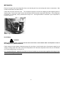
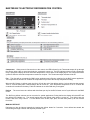
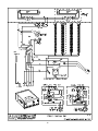
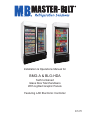
Installation & Operations Manual for
BMG-A & BLG-HDA
Self-Contained
Glass Door Merchandisers
With Lighted Graphic Panels
Featuring LAE Electronic Controller
PN 57-01892
Rev 02-03-11
TABLE OF CONTENTS
INTRODUCTION………………………………….……………………………………………………………………..……………3
STORE CONDITIONS………………………….……………….…..…………………………………………………...................3
WARNING LABELS AND SAFETY INSTRUCTIONS………..…..…………………………………………………..………….3
GENERAL INSTRUCTIONS……………………………………………………………………………………………..………….4
MECHANICAL……………………………………………………………………………………………………………..………….5
REFRIGERATION CONTROL……………...……………………………………………………………………………..……...6-7
SERVICE INSTRUCTIONS…………………………………..…………………………………………………………..………….8
TROUBLE SHOOTING……………………………………………………………………………………………………..………..8
CHECK LIST……………………………………………………………………………………………………………………..……9
CABINET CLEANING PROCEDURES…………………………………………………………………………………..……...…9
Cabinet Monthly Checklist…………………..……………………………………………………..……………...……10
PART LIST…………….…………………………………………………………………..………………………………...……….10
ACCESSORIES……….…………………………………………………………………..………………………………...……….11
SALE AND DISPOSAL…………………………………………………………………..………………………………...……….11
SIGN SCHEMATICS..……………………………………………………………………………………………………………….11
BMG WIRING DIAGRAM.……………………………………………………………….……........................................………12
BLG WIRING DIAGRAM...………………………………………………………………………………………………………....13
2
INTRODUCTION
Thank you for purchasing a Master-Bilt cabinet. This manual contains important instructions for installing, using,
cleaning, and servicing a Master-Bilt BLG/BMG case. A parts list is included with this manual. Read all these
documents carefully before installing or servicing your equipment.
STORE CONDITIONS
The Master-Bilt BLG/BMG cases are designed to operate in the controlled environment of an air-conditioned store. The
store temperature should be at or below 75°F and a relative humidity of 55% or less. At higher temperature or humidity
conditions, the performance of these cases may be affected and the capacity diminished.
The Master-Bilt BLG/BMG should not be positioned where it is directly exposed to rays of sun or near a direct source of
radiant heat or airflow. This will adversely affect the case and will result in poor performance.
If this case is to be located against a wall, there should be at least 4 to 6” space between the wall and the back of the
case. This space will allow for the circulation of air behind the case, which will prevent condensation on the exterior
surfaces.
WARNING LABELS AND SAFETY INSTRUCTIONS
This symbol is the safety-alert symbol. When you see this symbol on your cabinet or in this
manual, be alert to the potential for personal injury or damage to your equipment. Be sure you
understand all safety messages and always follow recommended precautions and safe
operating practices.
NOTICE TO EMPLOYERS
You must make sure that everyone who installs, uses or services your cabinet is thoroughly familiar with all
safety information and procedures.
Important safety information is presented in this section and throughout the manual. The following signal words are
used in the warnings and safety messages:
DANGER:
Severe injury or death will occur if you ignore the message.
WARNING: Severe injury or death can occur if you ignore the message.
CAUTION: Minor injury or damage to your cabinet can occur if you ignore the message.
NOTICE:
This is important installation, operation or service information. If you ignore the message, you may damage
your cabinet.
The warning and safety labels shown throughout this manual are placed on your Master-Bilt Products cabinet
at the factory. Follow all warning label instructions. If any warning or safety labels become lost or damaged,
call your customer service department at (800) 684-8988 for replacements
CAUTION!
GROUND REQUIRED
FOR SAFE OPERATION
This label is attached to the cabinet power cord
label and on the wiring channel.
This label is located on top of the electrical control
on models with a power cord.
3
NOTICE
Read this manual before installing, cleaning, or replace any maintenaNce on your cabinet. Keep the manual
and refer to it before doing any service on the equipment. Failure to do so could result in personal injury or
damage to the cabinet.
DANGER
Improper or faulty hook-up of electrical components on the refrigeration units can result in
severe injury or death. All electrical wiring hook-ups must be done in accordance with all applicable local,
regional or national standards.
NOTICE
Installation and service of the refrigeration and electrical components of the cabinet must be
performed by a refrigeration mechanic and/or a licensed electrician.
The portions of this manual covering refrigeration and electrical components contain technical instructions intended only
for persons qualified to perform refrigeration and electrical work. This manual cannot cover every installation, use or
service situation. If you need additional information, call or write us:
Customer Service Department
Master-Bilt Products
Highway 15 North
New Albany, MS 38652
Phone: (800) 684-8988
Fax: (800) 684-8988
GENERAL INSTRUCTIONS
1. Be sure the equipment is properly installed by competent service people.
2. Keep the equipment clean and sanitary so it will meet your local sanitation codes. Clean the cabinet with a mild
detergent and water, then rinse.
3. Rotate your stock so that older stock does not accumulate. This is especially important for ice cream. A "FirstIn, First-Out" rotation practice will keep the products in good salable condition.
4. Do not place product in the case when it is soft or partially thawed. Also, product should not be put in the case
for at least 6 hours after it is started.
5. Stock cases as quickly as possible, exposing only small quantities to store temperatures for short periods of
time.
6. When replacing burned out fluorescent tubes, be sure that the electrical power to the lighting circuit is turned off.
NOTICE TO STORE OWNERS / MANAGERS
Moisture or liquid around or under the cabinet is a potential slip/fall hazard for persons walking by or working
in the general area of the cabinet. Any cabinet malfunction or housekeeping problem that creates a slip/fall
hazard around or under the cabinet should be corrected immediately.
If moisture or liquid is observed around or under a Master-Bilt cabinet, an immediate investigation should be
made by qualified personnel to determine the source of the moisture or liquid. The investigation should
determine if the cabinet is malfunctioning or if there is a drain pipe leaking.
4
MECHANICAL
Remove front grille and check refrigeration lines to see that they are free (not touching each other or compressor). Spin
condenser fan blade to see that it is free.
Check that all service valves are open. The compressor springs are secured for shipping by either tightening bolts or
shipping strap. Remove the strap or loosen the hold-down bolts so that the compressor floats freely. If the compressor
is hermetic, it is internally spring mounted and ready to run. See figures below to determine if your compressor is
hermetic (Figure 1).
Fig. 1 - Hermetic Compressor
ELECTRICAL
WARNING
Before servicing electrical components in the case or the doors or door frames make sure all power to case is
off. Always use a qualified technician.
Check voltage and amps drawn to determine proper line and fuse or circuit breaker size. Check power supply for low
voltage. If voltage reads “230” with no load, and it drops below “207” when the compressor tries to start, it is an indication
of too small supply wiring or too long to run.
It is recommended that a separate circuit be run for each cabinet to prevent another appliance blowing the fuse
or breaker, causing loss of product.
5
MASTER-BILT ELECTRONIC REFRIGERATION CONTROL
Display Lay-out
Compressor When power is first turned on to the control, the LED indicator for the Thermostat output will go through
the start-up delay. After a one-minute delay the compressor comes on. The LED indicator stays on while compressor
relay is energized. Display will show actual box temperature. Picture above is the display layout. The compressor will be
cycled off when the actual box temperature reaches its set point. The Thermostat output indicator will be off.
Fan The fans will run constantly for BMG cooler application and off during a defrost for the BLG freezer application.
The Evaporator fan will also cut off when the evaporator temp is above the fan stop temperature setting.
When the BLG freezer in defrost mode; the fan is off until the end of the defrost and the 2 minute drip time has passed.
o
There is 2 minute delay after a defrost before the fan comes on. If the Evaporator temperature is 35 F or below the
controller will override the fan delay. FAN LED indicator is on while FAN relay is energized.
Defrost
cooler.
The control uses time defrost with 4 defrosts per day for the BLG freezer and off cycle defrost for the BMG
The BLG time defrost scheme can be re-set the for special applications. During defrost the display will show dEF and
the defrost LED indicator on. The control begins timing the defrost when power is turned on. Four defrost per day
means it will occur every 6 hours. To have defrost occur at 8am, 2pm, 8pm, and 2am then power up at one of these
four times.
MANUAL DEFROST
Defrosting my also be induced manually by keeping the defrost button for 5 seconds. Once defrost has started, the
defrost will go through a defrost and drip time pull down cycle.
6
HOW TO CHANGE THE SETPOINT
HOW TO CHANGE a parameter value
LIST OF PARAMETERS
Here is a list of the parameters the value of which can be changed in the programming mode, as well as their ranges.
Display
Symbol
SP
HYS
SPL
SPH
AHA
ALA
ATD
DFR
DLI
DTO
Parameter
Range
SPL…SPH
1 to 255°F
-50…SPH
SPH…120°
-50…120°
50…120°
0…120min
0…24
-50…120°
1…120min
Temperature Set Point
Temperature Differential
Minimum Temperature limit setpoint
Maximum Temperature limit setpoint
High Temperature Alarm
Low Temperature Alarm
Temperature Alarm Delay
Number of Defrost Cycle per 24hr
Defrost Termination Temperature
Maximum Defrost Duration
Master-Bilt’s
BLG Setting
-10°F
7°
-20°F
15°F
30°F
-40F
30min
4/day
55°F
30min
Master-Bilt’s
BMG Setting
35°F
5°
30°F
50°F
65°F
0°F
30min
Off Cycle
30min
ELECTRICAL CONNECTIONS
2
The controller is provided with a screw terminal block to connect cables with a cross section up to 2,5 mm . Before
connecting cables make sure the power supply complies with the control’s requirements. Separate the probe cables
from the power supply cables, the outputs and the power connections. Do not exceed the maximum current allowed on
each relay, in case of heavier loads use a suitable external relay or contactor’s.
PROBE CONNECTIONS
The probes shall be mounted with the bulb upwards to prevent damage due to casual liquid infiltration. It is
recommended to place the thermostat probe at the warmest loacation of return air streams to correctly measure the
average room temperature. Place the defrost termination probe among the evaporator fins in the coldest place, where
most ice is formed, far from heaters or from the warmest place during defrost, to prevent premature defrost termination.
7
SERVICE INSTRUCTIONS
4.
1.
High head pressure and high back pressure:
A. Condenser coil clogged or restricted
B. Condenser fan motor defective.
C. Air discharge in rear of cabinet restricted.
2.
Low back pressure and low head pressure:
A. Restriction in system.
B. Refrigerant undercharged.
C. Leak in system
3.
Pressure normal – cabinet warm:
A. Coil blocked with frost.
B. Refrigerant undercharged.
C. Control set too warm.
Cabinet not cycling – coil blocked with frost:
A. Defective temperature controller, or improper
settings.
B. Refrigerant overcharged.
C. Location too hot.
D. Condenser clogged.
E. Condenser fan motor defective.
F. For freezer, defrost heater not operating.
G. Air leakage into cabinet due to open door or faulty
door seal.
5. Compressor starts and runs – but cycles on overload:
A. Low voltage
B. Relay defective.
C. Overload defective.
D. High head pressure (see #1
TROUBLE SHOOTING
Symptom-System Operates Long or Continuously
POSSIBLE PROBLEM
POSIBLE CAUSE
REMEMDY
How Long do the doors stay open?
Door closer need adjust.
Adjust door closer and keep doors closed.
Is the condenser clean?
Dirty condenser.
Clean condenser
Are the condenser fans running?
Fans not running.
Repair or replace
Is the evaporator dirty or iced up?
Iced or plugged evaporator coil(s). Defrost or clean (check control settings)
Are the evaporator fans running?
Fans not running.
Repair or replace
have you checked the refrigerant level? Shortage of refrigerant.
Is there air or other non-condensables in Non-condensables in the system
the system?
Repair leak and recharge.
Evacuate and recharge.
Are all controls functioning properly?
Repair or adjust the control.
Control contacts or error codes.
Checked expansion valve for Freezers? Improper controls adjusted.
What is Evaporator Superheat?
Clean or replace.
Evaporator Superheat too high.
Adjust expansion valve to lower
Superheat setting.
Where is condensing Unit located?
Location too warm.
Ventilate area or change to cooler
Air leaks or doors
location.
Is Box well sealed from air penetrations? Wall panels not locked or wall
Seal leaks, and adjust doors or
pentrations not sealed.
replace.
Is system capacity sufficient for product Product load greater than system Sevice the units or replace.
load?
capacity.
CHECK LIST
A.
Check operating pressures.
B.
Check electrical requirements of unit to supply voltage.
C.
Set temperature control for desired temperature range.
D.
Check sight glass (if applicable) for proper refrigerant charge.
E.
Check system for proper defrost settings and operation.
F.
Check condensing unit for vibrating or rubbing tubing. Dampen and clamp as required.
G.
All valves should be completely opened counter-clockwise.
H.
Check packing nuts on all service valves.
I.
Replace all service valve caps and latch unit covers.
8
CABINET CLEANING PROCEDURES
WARNING!
To avoid electrical shock, disconnect main power supplies to the merchandiser
before beginning
this procedure may have more than one disconnect switch.
The exterior of the cabinet should simply be wiped clean with a damp cloth daily. This will be sufficient to keep the
merchandiser looking its finest. Do not use a brush, scouring pad, or any abrasive material on the painted
surfaces!
To clean the interior of the cabinet, the condensing unit and power to the merchandiser fans, lights, and heaters should
be shut off. Disconnect all power before cleaning! All product in the cabinet should be removed and stored in an
appropriate facility. All shelving, trays, etc. should be removed and cleaned separately.
The interior (as well as the exterior) of the cabinet may be cleaned with a germicidal detergent at the manufacturer’s
recommended concentration. Do not use any ammonia-based products as this may damage the electrical
components in the cabinet. Again, do not use a brush, scouring pad, or any abrasive material on the painted
surfaces. Use a soft brush or cleaner pad for built-up dirt, stains, or spills. Remove only the necessary mechanical
parts to access the evaporator coil and fan housing. Care should be taken not to unnecessarily soak fan motors,
electrical connections, controls, or any wire raceway. Wipe all surfaces with a damp cloth. A sanitizer should then be
thoroughly sprayed onto the surfaces and again wiped with a damp cloth.
Remove only the necessary mechanical parts to access the condenser coil and compressor housing. Care should again
be taken not to unnessarily soak fan motors, electrical connections, time clock, ballasts, or any wire raceway. Check the
condenser coil to insure that it is not clogged with dirt, dust, or lint. A dirty or clogged condenser coil will result in
diminished performance of the cabinet. The condenser should be brushed with a plastic bristled brush. For dust or dirt
that has accumulated deep inside the condenser, use compressed air to blow the dirt through the coil. Do not let dust or
dirt accumulate on the fan blades. If dust or dirt is noticeable, simply wipe the fan blades with a damp cloth as with other
surfaces. After cleaning, replace any equipment that was previously removed and start the condensing unit and return
power to the lights, fans, and heaters.
CLEANING: As a regular maintenance routine, the condenser coil should be cleaned approx every 6 to 12 months,
depending on store conditions.
Keep the equipment clean and sanitary so it will meet your local sanitation codes. Wipe up all spills, clean with water
and a mild detergent, then rinse with clean water. Wipe the exterior and gasket area as needed.
Cabinet Monthly Checklist
1. Check condenser coil, clean if necessary.
2. Check service valve packing for leaks evident by oil traces.
3. Check for obstruction restricting air flow over the evaporator coil and the condenser coil.
Insure that the air intake is not obstructed.
4. Check for excessive noise
5. Check for proper temperature, adjust if necessary.
6. Check door gaskets for proper seal against cabinet (when applicable).
Check doors for self closing, adjust tension if necessary (when applicable).
Check door frame heaters and door heaters for proper operation (when applicable).
7. Check for proper operation sequence in normal refrigeration cycle and defrost cycle (when applicable).
9
MASTER-BILT PART LIST
The table below gives Master-Bilt part numbers. Use this chart when ordering replacement parts for your BLG/BMG cabinets.
Always Advise Cabinet Serial Number When Ordering Parts
Description
Sign Ballast
Sign Light bulb
Sign Bulb Holder
Sign Lens
Coil Defrost Heater
Compressor
Compressor Contactor
Compressor Relay
Compressor Run Capacitor
Compressor Start Capacitor
Compressor Switch
Condensate Heater, BLG Electric (Optional)
Condenser Coil
Condenser Fan Blade
Condenser Fan Motor
Door Frame Heater
Door-L.H.
Door-R.H.
Drain Heater
Drier
Evaporator Coil
Evaporator Fan Blade
Evaporator Fan Guard
Evaporator Fan Motor
Expansion Valve
Capillary Tube
Female Door Plug
Female Plug
Front Control
Heater Safety Control
Leg Leveler
Light Switch
Electronic Controller
Box Temperature Sensor (T1)
Evap Temperature Sensor (T2)
Terminal Block
Power Cord
BMG-27
23-01709
23-01576
23-50562
29-01717
03-50330
-
BMG-48
23-01709
23-01575
23-50562
29-01716
03-50330
-
BMG-74
23-01709
23-01577
23-50562
29-01718
03-14799
-
19-13118
17-00380
07-13253
31-03084
N/A
09-09309
07-13293
15-13106
25-01324
13-13181
11-01450
21-00568
19-13118
19-14243
19-14244
19-14245
21-01454
19-13118
07-13253
31-03084
N/A
09-09309
07-13293
15-13106
25-01324
13-13181
11-01450
21-00568
19-13118
19-14243
19-14244
19-14245
21-01454
19-13118
07-13296
N/A
N/A
09-09309
07-13311
15-13106
25-01324
13-13181
11-01450
21-00568
19-13118
19-14243
19-14244
19-14245
21-01454
10
BLG-48
23-01709
23-01575
23-50562
29-01716
17-09522
03-14968
19-13934
03-14980
03-14978
03-14979
19-13118
17-00421
07-13090
15-13093
13-01283
17-09419
31-03081
31-03082
17-00404
09-09711
07-13289
15-13106
25-01324
13-13182
09-09758
21-00568
21-00577
19-13897
19-01164
27-00592
19-13118
19-14243
19-14244
19-14245
19-01091
21-01509
BLG- 74
23-01709
23-01577
23-50562
29-01718
N/A
03-14973
19-13934
03-14977
03-14975
03-14976
19-13118
17-00421
07-13090
15-13093
13-01283
17-09419
31-03081
31-03082
17-00404
09-09711
07-13290
15-13106
25-01324
13-13182
09-09759
21-00568
21-00577
19-13897
19-01164
27-00592
19-13118
19-14243
19-14244
19-14245
19-01091
21-01509
ACCESSORIES
Description
Baskets (Cantilever)
Baskets(Conventional)
Casters (4) 3” Diameter
Casters (6) 3” Diameter
Legs 6”
Shelves (Cantilever)
Shelve, Bottom
Shelving Clips (4)
BMG-27
BMG-48
A200-11140 A200-11140
A200-11170 A200-11170
33-01473
33-01474
-
BMG-74
A200-11170
33-01474
-
BLG-48
33-01458
33-01376
A200-11140
A212-11140
A200-11170
33-01475
33-01448
33-01011
BLG- 74
33-01458
33-01419
A212-11140
A212-11170
33-01474
33-01453
33-01011
SALE AND DISPOSAL
OWNER RESPONSIBILITY
If you sell or give away your Master-Bilt cabinet you must make sure that all safety labels and the Installation - Service
Manual are included with it. If you need replacement labels or manuals, Master-Bilt will provide them free. Contact the
customer service department at Master-Bilt at (800) 684-8988.
The customer service department at Master-Bilt should be contacted at the time of sale or disposal of your cabinet so
records may be kept of its new location.
11
12
13