1
Multimedia Projector
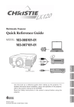
Quick Reference Guide
103-008100-01
Italiano
READ THE SAFETY INSTRUCTIONS IN THE USER’S MANUAL
BEFORE USING THE PROJECTOR.
Español
Use this book as a reference guide when setting up the
projector. For detailed information about installation, setup,
and operation of the projector, refer to the user’s manual on
the CD-ROM.
Deutsch
✽ Projection lens is optional.
Français
English
MODEL
Downloaded
projector-manual.com Christie Manuals
Printed From
in Japan
Part No. 610 330 3840 (1AA6P1P5215-- KE6KL)
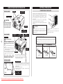
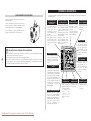
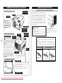
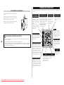
NAME OF EACH PART OF PROJECTOR
FRONT OF CABINET
SPEAKERS
SETTING-UP PROJECTOR
CONNECTING AC POWER CORD
TOP CONTROLS
AND INDICATORS
This projector uses nominal input voltages of 100-120 V or
200-240 V AC and it automatically selects correct input
voltage. It is designed to work with single-phase power
systems having a grounded neutral conductor. To reduce
risk of electrical shock, do not plug into any other type of
power system.
If you are not sure of the type of power being supplied,
consult your authorized dealer or service station.
Connect the projector with all peripheral equipment before
turning it on.
PROJECTION LENS ✽
✽ optional
CAUTION
Do not turn on the projector
with the lens cap attached.
High temperature from light
beam may damage the lens
cap and result in fire hazard.
AIR INTAKE
VENT
INFRARED
REMOTE RECEIVER
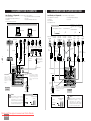
BACK OF CABINET
POWER CORD
CONNECTOR
TERMINALS
AND CONNECTORS
Connect AC power cord (supplied) to the
projector.
The AC outlet must be near this equipment and
must be easily accessible.
INFRARED
REMOTE RECEIVER
EXHAUST VENT
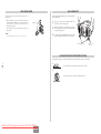
NOTE ON POWER CORD
-2-
AC power cord must meet the requirements of the country where you use the projector.
Confirm the AC plug type with the chart below and a proper AC power cord must be
used.
If the supplied AC power cord does not match your AC outlet, contact your sales dealer.
HOT AIR EXHAUSTED !
Air blown from the exhaust vent is hot.
When using or installing the projector,
the following precautions should be
taken.
● Do not put a flammable object near this
vent.
● Keep the rear grills at least 3.3’ (1 m)
away from any object, especially from
heat-sensitive objects.
● Do not touch this area, especially
screws and metallic parts. This area will
become hot when the projector is in
use.
This projector detects internal
temperature and automatically controls
operating power of the cooling fans.
CAUTION
For safety, unplug the AC power cord when the projector is not
in use. When the projector is connected to an outlet with AC
power cord, an appliance is in stand-by mode and consumes a
little electric power.
Projector side
AC Outlet side
For the U.S.A. and Canada
CARRYING
HANDLE
For Continental Europe
Ground
LAMP COVER
When attaching the PJ-Net organizer
(optional) to the projector, remove the
these parts. Refer to the user's manual
of the optional PJ-Net organizer.
BOTTOM OF CABINET
AIR INTAKE VENTS
This projector is equipped with cooling fans for protecting
from overheating. Pay attention to the followings to
ensure proper ventilation and avoid a possible risk of fire
and malfunction.
● Do not cover the vent slots.
● Keep this side clear of any objects. Obstructions may
block cooling the air.
ADJUSTABLE FEET
AND
FEET LOCK LATCHES
Downloaded From projector-manual.com Christie Manuals
To POWER CORD
CONNECTOR on your
projector.
To the AC Outlet.
(120 V AC)
To the AC Outlet.
(200 - 240 V AC)
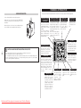
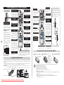
LENS INSTALLATION
ADJUSTABLE FEET
Before setting up the projector, install a projection lens on
the projector.
1. Before installation, check the area where the projector is
used and prepare a suitable lens. For the specifications of
a projection lens, contact sales dealer where you
purchased the projector.
2. For installation, refer to the installation manual of the
optional lens.
Projection angle can be adjusted up to 10.5 degrees with the
ADJUSTABLE FEET.
COVER CAP
✔Note:
•When installing the lens, remove the cover cap of the projector.
1
Lift the front of the projector and pull the FEET LOCK
LATCHES in each side of the projector.
2
Release the FEET LOCK LATCHES to lock the
ADJUSTABLE FEET and rotate the ADJUSTABLE FEET
to a proper height, and tilt.
3
To retract the ADJUSTABLE FEET, lift the front of the
projector and pull and undo the FEET LOCK LATCHES.
ADJUSTABLE FEET
FEET LOCK
LATCHES
INSTALLING PROJECTOR IN PROPER POSITION
Install the projector properly. Improper installation may reduce the lamp life and cause a fire hazard.
-3-
10˚
Do not tilt the projector more than 10 degrees from side to side.
10˚
Do not put the projector on either side to project an image.
NO SIDEWAYS
Downloaded From projector-manual.com Christie Manuals
English
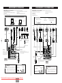
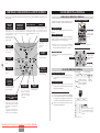
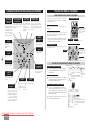
TERMINALS OF PROJECTOR
MOVING PROJECTOR
This projector has input and output terminals on its back for connecting computers and video equipment.
Use the Carrying Handle when moving the projector.
Replace the lens cap and retract the ADJUSTABLE FEET
when moving the projector to prevent damages to the lens
and cabinet.
When this projector is not in use for an extended period, put
it into a suitable case (not supplied with this projector).
COMPUTER AUDIO INPUT
1/ AUDIO MONITOR
OUTPUT JACK
This terminal is switchable
and can be used as
Computer Audio Input 1 or
Audio Monitor Output
(variable).
Set up the terminal as
either Computer Audio
Input 1 or Audio Monitor
Output properly before
using this terminal.
COMPUTER INPUT/MONITOR
OUTPUT TERMINAL (ANALOG)
COMPUTER INPUT
TERMINAL (DIGITAL)
COMPUTER AUDIO
INPUT 2 JACK
This terminal is switchable
and can be used as Computer
Input or Monitor Output. Set
up the terminal as either
Computer Input or Monitor
Output properly before using
this terminal.
Note: This terminal outputs
from the 5 BNC type
computer input on INPUT 2
jacks only.
Connect a computer
output (Digital DVI-D
type) to this terminal.
The
HD
(HDCP
Compatible) signal can
also be connected.
Connect an audio
output (stereo) from
a computer to this
jack.
R/C JACK
When
using
the
Wired/Wireless remote
control as wired, connect
the Wired remote control
to this jack with a remote
control cable (optional).
USB CONNECTOR (Series B)
CAUTION IN CARRYING OR TRANSPORTING A PROJECTOR
-4-
● Do not drop or bump the projector, otherwise damages or malfunctions may result.
● When carrying the projector, use a suitable carrying case.
● Do not transport the projector by courier or any other transport service in an unsuitable transport case.
This may cause damage to the projector. To transport the projector by courier or any other transport
service, consult your dealer for the best way.
When controlling a computer
with the remote control of
this projector, connect USB
terminal of your personal
computer to this terminal.
This projector uses a micro
processor to control the unit, and
only occasionally, this micro
processor may malfunction and
need to be reset. This can be
done by pressing the RESET
button with a pen, which will shut
down and restart the unit. Do not
use
the
RESET
function
excessively.
5 BNC INPUT JACKS
Connect component video
output (Y, Cb, Cr or Y, Pb,
Pr) from video equipment
to VIDEO/Y, Cb/Pb and
Cr/Pr jacks or connect
computer output {5 BNC
Type (Green, Blue, Red,
Horiz. Sync, and Vert.
Sync.)} from computer to
G, B, R, H/V, and V jacks.
Downloaded From projector-manual.com Christie Manuals
CONTROL PORT CONNECTOR
When
controlling
a
computer with the remote
control of this projector,
connect the mouse port of
your personal computer to
this connector.
RESET BUTTON
VIDEO INPUT JACKS
AUDIO INPUT JACKS
S-VIDEO INPUT JACK
Connect composite
video output from video
equipment to VIDEO/Y
jack
or
connect
component
video
outputs to VIDEO/Y,
Cb/Pb and Cr/Pr jacks.
Connect an audio
output from video
equipment to these
jacks.
Connect S-VIDEO
output from video
equipment to this
jack.
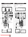
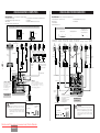
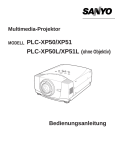
CONNECTING TO COMPUTERS
CONNECTING TO VIDEO EQUIPMENT
Cables used for connection
Cables used for connection (✽ = Cables not supplied with this projector.)
(✽ = Cables or adapters not supplied with this projector.)
• VGA Cable (HDB 15 pin)
• Control Cable for PS2 Port ✽, or ADB Port ✽
• USB Cable
• DVI-Digital Cable (for Single Link T.M.D.S.) ✽
• BNC Cable ✽
• Audio Cables (Mini Plug (stereo) x 2) ✽
• Control Cable for Serial Port
• Video Cable (RCA x 1 or RCA x 3) ✽
• BNC Cable ✽
• S-VIDEO Cable ✽
• Audio Cable (RCA x 2) ✽
IBM-compatible computer or Macintosh computer (VGA/SVGA/XGA/SXGA/SXGA+/WXGA/UXGA )
• Audio Cable {Mini Plug (stereo)} ✽
• Scart Cable ✽
Video Source (Example)
Component video output equipment.
Video Cassette Recorder
Desktop type
Monitor Output
Monitor Output Monitor Output USB port
or
Monitor Input
Audio Output
Serial port
PS/2 port
ADB port
Terminal
Terminal
Terminal
Component Video
Output
(Y, Cb/Pb, Cr/Pr)
Composite
Video Output
RGB Scart
21-pin Output
Control Cable Control Cable
Control Cable
for Serial Port for PS/2 Port ✽ for ADB Port ✽
Audio
Cable ✽
(stereo)
USB
Cable
DVI
Cable ✽
VGA Cable
BNC
Cable ✽
Video Disc Player
(such as DVD players or high-definition TV sources.)
Laptop type
Composite
Video Output
Component Video
Output
(Y, Cb/Pb, Cr/Pr)
Audio Output Audio Output
Video Cables
(RCA x 1 or
RCA x 3) ✽
Scart Cable
✽
Audio
Cable ✽
(stereo)
BNC Cable ✽
-5-
COMPUTER
AUDIO IN 1 or 2
USB
COMPUTER IN ANALOG
COMPUTER IN DIGITAL
Use one of these
control cables
corresponding to the
terminal of your
computer.
This terminal is switchable.
Set up the terminal as either
Computer input or Monitor
output before using this
terminal.
CONTROL PORT
AUDIO 2
AUDIO OUT
G
B
VIDEO/Y
Cb/Pb
Y - Cb/Pb - Cr/Pr
AUDIO IN
AUDIO IN
✔Note:
R/C JACK
✔Note:
VIDEO
COMPUTER IN ANALOG
DIGITAL(DVI-D)
RESET
USB
Y - Cb/Pb Cr/Pr
Audio Cable
(RCA x 2) ✽
CONTROL
PORT
INPUT 1
ANALOG IN/OUT
AUDIO 1
IN/OUT
VIDEO
S-VIDEO
Output
R
H/V
V
This terminal is switchable. Set up the terminal
as either Computer Audio Input 1 or Audio
Monitor Output (variable) before using this
terminal.
AUDIO OUT
Cr/Pr
INPUT 2
VIDEO/Y Cb/Pb
Cr/Pr
R—AUDIO—L
S—VIDEO
(MONO)
INPUT 3
Audio Cable
(stereo) ✽
Audio Cable
(stereo) ✽
✔Note:
This terminal is switchable.
Set up the terminal as
either Computer input or
Monitor output before
using this terminal.
Terminals
of the Projector
Audio Input
External Audio Equipment
✔Note:
Unplug the power codes of both the
projector and external equipment from the
AC outlet before connecting cables. Turn a
projector and peripheral equipment on
before computer is switched on.
Audio Amplifier
Terminals
of the Projector
Audio Input
Audio Speakers
(stereo)
External Audio Equipment
Audio Amplifier
Downloaded From projector-manual.com Christie Manuals
English
Audio Speakers
(stereo)
✔Note:
Unplug the power codes of both the
projector and external equipment from the
AC outlet before connecting cables. Turn a
projector and peripheral equipment on
before computer is switched on.
S-VIDEO
Cable ✽
S-VIDEO
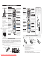
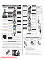
REMOTE CONTROL OPERATION
Left Side
LASER POINTER
(DRAG ON) INDICATOR
D.ZOOM BUTTON
Lights red while the laser
beam is emitted from the
Laser Light Window.
Lights green when dragged
to the “ON” position.
Used to mute the sound.
IMAGE BUTTON
DRAG ON/OFF BUTTON
Used to select the image
level.
-6-
ALL OFF SWITCH
Used to select the DRAG
When using the remote control, ON/OFF position.
turn this switch to “ON.” And turn LEFT CLICK BUTTON
it to “ALL OFF” when it is not in
Used as a PC mouse in
use.
Wireless
Mouse
INSIDE THE BATTERY
Operation. Press this
COMPARTMENT BOX
button and the mouse
This Remote Control provides the pointer button to drag the
DIP switches into the battery selected screen object.
compartment box.
Slide the SW4 (LASER ON/OFF LASER BUTTON
switch) to the “OFF” position. The
Used to operate the Laser
Laser Pointer function is not
Pointer function. The laser
operated.
beam is emitted when
Set the Switches 1-3 as shown in
pressing this button for
table below depending on the
one minute.
Code No. that you want to select
When using the Laser
as the remote control code.
Pointer for more than one
minute, release this
button and press it again.
DIP SWITCH SETTING
KEYSTONE BUTTON
Used to correct keystone
distortion.
RIGHT CLICK BUTTON
Used as a PC mouse in
Wireless Mouse Operation.
4
3
ON
2
1
Code 1
Code 2
Code 3
Code 4
Code 5
Code 6
Code 7
Code 8
Used to turn the picture
into a black image.
FREEZE BUTTON
Used to
picture.
Used to execute the
selected item, or
expand/ compress the
image in the DIGITAL
ZOOM +/- mode.
WIRED REMOTE JACK
When using as a Wired
Remote Control, connect a
remote control cable (not
supplied) to this jack.
Battery installation is
required when using as a
Wired Remote Control.
FOCUS BUTTON
Used to adjust focus.
LASER POINTER FUNCTION
This remote control emits laser beam from the Laser Light Window when used as a Laser Pointer. When the
LASER button is pressed, the laser light goes on. When the LASER button is being pressed for more than one
minute or when it is released, the light goes off. The LASER POINTER INDICATOR lights RED and the LASER
is emitted with RED light to indicate the laser beam is being emitted.
The Laser emitted is the Cass II laser. Do not look into the Laser Light Window or shine laser beam onto
yourself or other people. The three marks shown below are caution labels for the laser beam.
CAUTION: Use of controls, adjustments, or performance of procedures other than those specified herein may
result in hazardous radiation exposure.
These caution labels are put on the remote control.
LASER POINTER INDICATOR
LASER LIGHT
WINDOW
Downloaded From projector-manual.com Christie Manuals
the
Used to select an item or
adjust a value in OnScreen Menu. They are
also used to pan the
image in the DIGITAL
ZOOM +/- mode.
The POINT LEFT/RIGHT
buttons are also used as
VOLUME +/- buttons.
MENU BUTTON
Used to select the
MENU Operation.
P-TIMER BUTTON
Used to operate the PTIMER function.
Operating Range
Point the remote control
toward the projector (a
Receiver Window) when
pressing
any
button.
Maximum operating range for
the remote control is about
16.4’ (5 m) and 60° in front
and rear of the projector.
60°
16.4’
(5 m)
INPUT 1 BUTTON
Used to select an input
source (INPUT 1).
ZOOM BUTTON
INPUT 2 BUTTON
Used to select an input
source (INPUT 2).
Used to adjust zoom.
Used to select the Lens
Shift function.
freeze
POINT (VOLUME +/-)
BUTTONS
LENS SHIFT BUTTON
SW1 SW2 SW3 Code No.
ON
OFF
ON
OFF
ON
OFF
ON
OFF
NO SHOW BUTTON
Used to select the
DIGITAL ZOOM +/–
mode and resize the
image.
SELECT BUTTON
MOUSE POINTER
Used as a PC mouse in
Wireless Mouse Operation.
SW4 ........ LASER ON/OFF
ON
ON
OFF
OFF
ON
ON
OFF
OFF
AUTO PC ADJ. BUTTON
Use to operate the AUTO
PC Adjustment function.
MUTE BUTTON
ON
ON
ON
ON
OFF
OFF
OFF
OFF
POWER ON-OFF BUTTON
Used to turn the projector
on or off.
INPUT 3 BUTTON
Used to select an input
source (INPUT 3).
COLOR MANAGEMENT
BUTTON
Used to operate the
Color management
function.
16.4’
(5 m)
60°
NETWORK BUTTON
Used to select a
network input (optional).
REMOTE CONTROL BATTERIES INSTALLATION
1
Open the battery
compartment lid.
Press
the
lid
downward and slide it.
2
Install new batteries
into the compartment.
3
Replace the compartment
lid.
Two
AA
size
batteries
For correct polarity (+
and –), be sure battery
terminals
are
in
contact with pins in
the compartment.
To insure safe operation, please observe following precautions:
● Use two (2) AA or LR6 type alkaline batteries.
● Always replace batteries in sets.
● Do not use a new battery with an used battery.
● Avoid contact with water or liquid.
● Do not expose the remote control to moisture, or heat.
● Do not drop the remote control.
● If a battery has leaked on the remote control, carefully wipe the case clean and install new
batteries.
● Danger of explosion if battery is incorrectly replaced.
● Dispose of used batteries according to batteries manufacturers instructions and local rules.
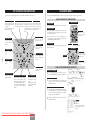
TOP CONTROLS AND INDICATORS
ON-SCREEN MENU
This projector has CONTROL BUTTONS (TOP CONTROLS) and INDICATORS on its top.
LAMP REPLACE INDICATOR
WARNING TEMP. INDICATOR
READY INDICATOR
Turns to yellow when the
projection lamp reaches its
end of life.
Blinks yellow when the
lamp cannot light up.
Blinks red when the
internal temperature of
the projector is too high.
Lights green when
the projector is ready
to be turned on. And
it blinks green in the
Power management
mode.
You can control and adjust this projector with On-Screen Menu. For details, refer to the user’s manual.
HOW TO OPERATE ON-SCREEN MENU
LAMP INDICATOR
Becomes dim when the
projector is turned on.
And it becomes bright
when the projector is in
stand-by mode.
POWER ON–OFF BUTTON
MENU BUTTON
Used to turn the
projector on or off.
Used to open or
close the On-Screen
Menu.
REMOTE CONTROL
1. DISPLAY MENU
Press the MENU button to display the On-Screen Menu.
2. MOVING POINTER
Move the pointer (✽ see below) or adjust a value of an
item by pressing the POINT buttons on the top control
or on the remote control.
✽ The Pointer is an icon in the On-Screen Menu for
selecting an item. See figures in “FLOW OF ONSCREEN MENU OPERATION” below.
3. SELECT ITEM
INPUT BUTTON
Used to select an
input source.
ZOOM BUTTON
-7-
Used to adjust
zoom.
AUTO PC ADJ. BUTTON
FOCUS BUTTON
Used to operate the
Auto PC Adjustment
function.
POINT BUTTONS
Used to move the
Pointer UP/DOWN/
RIGHT/LEFT.
MENU BUTTON
Select an item or set the selected function by pressing
the SELECT button.
SELECT BUTTON
Used to select the item.
TOP CONTROL
POINT BUTTONS
Used to move the
Pointer UP/ DOWN/
RIGHT/ LEFT.
MENU BUTTON
SELECT BUTTON
Used to adjust
focus.
Used to select the
item.
FLOW OF ON-SCREEN MENU OPERATION
IMAGE BUTTON
Used to select the
image level.
1
LENS SHIFT BUTTON
Used to select the
Lens Shift function.
Display ON-SCREEN MENU
POINT (VOLUME + / – ) BUTTONS
SELECT BUTTON
Used to select an item or adjust a
value in On-Screen Menu. They
are also used to pan the image in
the DIGITAL ZOOM +/– mode.
The POINT LEFT/RIGHT buttons
are also used as VOLUME +/–
buttons.
Used to execute the
selected item. It is also
used
to
expand/compress the
image in the DIGITAL
ZOOM mode.
Select Menu to be adjusted
2
MENU BAR
MENU ICON
Press the MENU button to display the On-Screen
Menu (a MENU BAR). A red frame is a POINTER.
Move the POINTER (red frame) to a MENU ICON
that you want to select by pressing the POINT
RIGHT/LEFT buttons.
POINTER
POINTER (red frame)
Press the POINT UP/DOWN (red frame)
buttons to move the
POINTER.
ITEM
Control or adjust items through ON-SCREEN MENU
3
Press the POINT UP/DOWN buttons and move the
POINTER (red frame or red arrow) to an ITEM that
you want to adjust, and then press the SELECT
button to show the ITEM DATA.
4
Adjust the ITEM DATA by pressing the POINT
RIGHT/LEFT buttons.
SELECT
BUTTON
ITEM DATA
Press the POINT LEFT/RIGHT
buttons to adjust a value or set
a function.
Downloaded From projector-manual.com Christie Manuals
English
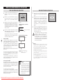
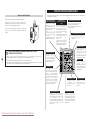
TURNING ON / OFF PROJECTOR
TURNING ON THE PROJECTOR
1
Complete peripheral connections (with a computer,
VCR, etc.) before turning on the projector.
2
Connect the projector’s AC power cord into an AC
outlet. The LAMP indicator lights RED, and the READY
indicator lights GREEN.
3
Press the POWER ON-OFF button on the top control or
on the remote control. The LAMP indicator dims, and
the cooling fans start to operate. The preparation
display appears on the screen and the countdown
starts.
4
After the countdown, the input source that was
selected the last time and the Lamp control status icon
appear on the screen.
TURNING OFF THE PROJECTOR
1
Press the POWER ON-OFF button on the top control or
on the remote control, and “Power off?” appears on
the screen.
2
Press the POWER ON-OFF button again to turn off the
projector. The LAMP indicator lights bright and the
READY indicator turns off. After the projector is turned
off, the cooling fans operate (for 90 seconds). During
this “cooling down” period, the projector cannot be
turned on.
16
The preparation display disappears after 30
seconds.
Selected Input Source and Lamp control
Lamp control status
3
When the projector has cooled down, the READY
indicator lights GREEN again and you can turn projector
on. After cooling down completely, unplug the AC
power cord.
TO MAINTAIN THE LIFE OF LAMP, ONCE YOU
TURN THE PROJECTOR ON, WAIT AT LEAST
FIVE MINUTES BEFORE TURNING IT OFF.
DO NOT UNPLUG THE AC POWER CORD WHILE
COOLING FANS ARE RUNNING OR BEFORE THE
READY INDICATOR LIGHTS GREEN AGAIN.
OTHERWISE IT WILL RESULT IN SHORTENING
THE LAMP LIFE.
If the projector is locked with a PIN code, a PIN code
Input Dialog Box appears. Enter a PIN code as
instructed below.
PIN code Input Dialog Box
To Enter a PIN code
Pointer
-8-
Select a number by pressing the POINT LEFT/RIGHT button
and fix the number with the SELECT button. The number
changes to “✳.” If you fixed a wrong number, move the
pointer to “Set” or “Clear” once by pressing the POINT
DOWN button, then return to “PIN code.” Enter the correct
number.
✔Note:
Repeat this step to complete entering a four-digit number.
When the four-digit number is fixed, the pointer
automatically moves to “Set.” Press the SELECT button so
that you can start to operate the projector.
After the OK icon disappears, you
can operate the projector.
If you entered a wrong PIN code, “PIN code” and the
number (✳✳✳✳) turn red and disappear. Enter a PIN code
all over again.
What is PIN code?
PIN (Personal Identification Number) code is a security code
that allows the person who knows it to operate the
projector. Setting a PIN code prevents unauthorized use of
the projector.
A PIN code consists of a four-digit number.
Refer to the PIN code lock function in SETTING Menu in the
user’s manual for locking the operation of the projector with
your PIN code.
CAUTION ON HANDLING PIN
CODE
If you forget your PIN code, the
projector can no longer be started.
Take special care in setting a new
PIN code; write down the number
in a column on page 60 of the
user’s manual and keep it at hand.
Should the PIN code be missing or
forgotten, consult your dealer or
service center.
Downloaded From projector-manual.com Christie Manuals
•The projector cannot be turned on during the cooling period with the
READY indicator turned off. You can turn it on again after the
READY indicator becomes GREEN again.
•When the On start function is “On,” this projector is turned on
automatically by connecting the AC power cord to an AC outlet.
• Continuous use may result in shortening the lamp life. Turn off the
projector and rest it for about an hour in every 24 hours.
•The running speed of cooling fans is changed according to the
temperature inside the projector.
•If the WARNING TEMP indicator blinks RED, see “WARNING
TEMP INDICATOR” in the user’s manual.
“Power off?” disappears after 4 seconds.
Projecteur multimédia
Guide de référence rapide
103-008100-01
✽ La lentille de projection est
disponible en option.
Utilisez ce livret comme guide de référence lorsque vous
installez le projecteur. Pour plus de détails concernant
l'installation, la configuration et l'utilisation du projecteur,
reportez-vous au mode d'emploi inclus dans le CD-ROM.
LISEZ LES INSTRUCTIONS DE SÉCURITÉ DANS LE MODE
D'EMPLOI AVANT D'UTILISER LE PROJECTEUR.
Downloaded From projector-manual.com Christie Manuals
Français
MODÈLE
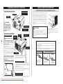
NOM DES COMPOSANTS DU PROJECTEUR
AVANT DU COFFRET
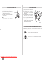
BRANCHEMENT DU CORDON D’ALIMENTATION SECTEUR
COMMANDES ET
TEMOINS SUR LE
PROJECTEUR
HAUT-PARLEURS
LENTILLE DE
PROJECTION
option
✽ En
ATTENTION
N’allumez pas le projecteur en
laissant le capuchon de lentille
en place. La haute température
produite par le faisceau
lumineux risque d’endommager
le capuchon de lentille et de
causer un incendie.
ARRIERE DU COFFRET
OUVERTURES DE VENTILATION
OUVERTURE
D’ENTREE D’AIR
RECEPTEUR
INFRAROUGE DE
TELECOMMANDE
CONNECTEUR DE
CORDON
D’ALIMENTATION
BORNES ET
CONNECTEURS
RECEPTEUR
INFRAROUGE DE
TELECOMMANDE
- 10 -
SORTIE D’AIR CHAUD!
Ce projecteur détecte la température
interne et contrôle automatiquement la
puissance de fonctionnement des
ventilateurs de refroidissement.
DESSOUS DU COFFRET
Ce projecteur utilise une tension nominale d’entrée de 100120 V CA ou 200-240 V CA. Le projecteur fera
automatiquement la sélection de la tension d’entrée
correcte. Il est conçu pour fonctionner avec des systèmes
d’alimentation monophasé avec conducteur neutre de prise
de terre. Pour réduire les risques de décharge électrique,
ne branchez pas le projecteur dans un autre type de
système d’alimentation.
Consultez votre revendeur autorisé ou un centre de service
en cas de doute sur l’alimentation actuellement utilisée.
Branchez le projecteur à l’équipement périphérique avant
d’allumer le projecteur.
Branchez le cordon d’alimentation secteur
(fourni) au projecteur.
La prise de courant doit se trouver à
proximité de cet appareil et être facilement
accessible.
ATTENTION
Par mesure de sécurité, débranchez le cordon d’alimentation
secteur lorsque vous n’utilisez pas l’appareil.
Lorsque ce projecteur est raccordé à une prise de courant par le
cordon d’alimentation secteur, l’appareil est en mode d’attente
et consomme une petite quantité de courant.
REMARQUE CONCERNANT LE CORDON D’ALIMENTATION
L’air soufflé par les ouvertures de
ventilation est chaud. Lors de
l’utilisation ou de l’installation du
projecteur, prenez les précautions
suivantes.
● Ne placez pas un objet inflammable près de
cette zone.
● Veillez à ce que les grilles arrière soient au
moins à 1 m de tout objet, en particulier des
objets sensibles à la chaleur.
● Ne touchez pas cette zone, en particulier les
vis et les pièces métalliques. La température
de cette zone augmente considérablement
lorsque le projecteur est utilisé.
INSTALLATION DU PROJECTEUR
POIGNEE DE
TRANSPORT
Le cordon d’alimentation secteur doit être conforme aux normes d’utilisation
en vigueur dans le pays où vous utilisez le projecteur.
Vérifiez le type de fiche secteur en vous référant au tableau ci-dessous; il faut
utiliser le cordon d’alimentation secteur adéquat. Si le cordon d’alimentation
secteur fourni n’est pas adapté à la prise secteur, adressez-vous à votre
revendeur.
Côté projecteur
COUVERCLE DE
LA LAMPE
Côté prise secteur
Pour les Etats-Unis et
le Canada
Masse
Lorsque vous fixez l’agenda électronique PJNet (pièce en option) au projecteur, retirez
ces pièces. Reportez-vous au mode
d’emploi de l’agenda électronique PJ-Net en
option.
OUVERTURES D’ENTREE D’AIR
Ce projecteur est équipé de ventilateurs de protection
pour le protéger de la surchauffe. Faites attention aux
points suivants pour garantir une bonne ventilation et
éviter tout risque d’incendie ou de mauvais
fonctionnement.
● N’obstruez pas la fente de ventilation.
● Veillez à ce qu’il n’y ait aucun objet des deux côtés du
projecteur. Ces obstacles risqueraient d’empêcher le
projecteur d’aspirer l’air de refroidissement par les
ouvertures d’entrée d’air.
PIEDS REGLABLES ET
VERROUS DE PIED
Downloaded From projector-manual.com Christie Manuals
Vers le connecteur du
cordon d’alimentation
du projecteur
Pour l’Europe
continentale
Vers la prise secteur
(120 V CA)
Vers la prise secteur
(200 - 240 V CA)
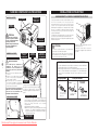
INSTALLATION DE LA LENTILLE
Avant d’installer le projecteur, installez la lentille de
projection sur le projecteur.
1. Avant de procéder à l’installation, vérifiez l’endroit où le
projecteur doit être utilisé, et préparez une lentille adéquate.
Pour plus de détails concernant les spécifications de la
lentille de projection, adressez-vous au magasin où vous
avez acheté le projecteur.
2. Pour plus de détails concernant l’installation, reportezvous au manuel d’installation de la lentille en option.
PIEDS REGLABLES
Vous pouvez régler l’angle de projection jusqu’à 10,5
degrés à l’aide des pieds réglables.
CACHE
1
Soulevez l’avant du projecteur et tirez les verrous
des pieds des deux côtés du projecteur.
2
Libérez les verrous des pieds pour verrouiller les
pieds réglables, et tournez les pieds réglables pour
ajuster la position et l’inclinaison.
3
Pour rétracter les pieds réglables, soulevez l’avant
du projecteur, tirez et libérez les verrous des pieds.
✔Remarque:
•Lorsque vous installez la lentille, retirez le cache du projecteur.
La déformation de trapèze d’une image projetée
peut être corrigée à l’aide de l’opération par menu.
Pieds réglables
Verrous des pieds
réglables
INSTALLATION DU PROJECTEUR A UNE POSITION CORRECTE
- 11 -
Installez le projecteur à une position correcte. Si vous l’installez à une position incorrecte, vous risquez de
réduire la durée de vie de la lampe et de provoquer un incendie.
10˚
Ne penchez pas le projecteur de plus de 10 degrés d’un côté à l’autre.
10˚
Ne placez pas le projecteur sur l’un de ses côtés pour projeter une image.
NE PAS PLACER
SUR LES COTES
Downloaded From projector-manual.com Christie Manuals
Français
BORNES DU PROJECTEUR
DEPLACEMENT DU PROJECTEUR
Lorsque vous déplacez le projecteur, tenez-le par sa
poignée de transport.
Lorsque vous déplacez le projecteur, remettez le cache
de lentille en place et rétractez les pieds afin d’éviter
d’endommager la lentille et le coffret de l’appareil.
Si vous n’utilisez pas ce projecteur pendant une durée
prolongée, remettez-le dans son étui (non fourni).
Ce projecteur est équipé de bornes d’entrée et de sortie sur son côté arrière pour connecter des ordinateurs et
des appareils vidéo.
CONNECTEUR D’ENTREE AUDIO 1
D’ORDINATEUR/SORTIE DE
MONITEUR AUDIO
Cette borne peut être
commutée et utilisée
comme entrée audio 1
d’ordinateur ou comme
sortie de moniteur audio
(variable).
Avant d’utiliser cette
borne, réglez correctement
la borne comme entrée
audio 1 d’ordinateur ou
comme sortie de moniteur
audio.
BORNE D’ENTREE D’ORDINATEUR/SORTIE
DE MONITEUR (ANALOGIQUE)
Cette borne peut être
commutée et utilisée comme
entrée d’ordinateur ou comme
sortie de moniteur. Avant
d’utiliser cette borne, réglez
correctement la borne comme
entrée d’ordinateur ou comme
sortie de moniteur.
Remarque: Cette borne
effectue la sortie des prises
d’entrée d’ordinateur de type
5 BNC sur les connecteurs
INPUT 2 seulement.
PRECAUTION POUR LE TRANSPORT DU PROJECTEUR
- 12 -
● Evitez absolument de laisser tomber ou de percuter le projecteur, sinon il pourrait subir des dommages
ou présenter des anomalies de fonctionnement.
● Pour transporter le projecteur, utilisez un étui de transport adéquat.
● Ne confiez le transport du projecteur à un agent de transport qu’après l’avoir mis dans un étui de
transport adéquat. Sinon, le projecteur risquerait d’être endommagé. Pour faire transporter le projecteur
par un agent de transport, demandez conseil à votre revendeur.
CONNECTEUR USB (Série B)
Pour commander l’ordinateur
avec la télécommande de ce
projecteur, connectez la borne
USB de votre ordinateur à cette
borne.
TOUCHE DE REMISE A ZERO
(RESET)
Ce projecteur utilise un microordinateur pour contrôler l’appareil. Il
est possible que le micro-ordinateur
fonctionne parfois incorrectement et
qu’il soit nécessaire de le remettre à
zéro. Vous pouvez effectuer ceci en
appuyant sur la touche RESET avec
un stylo; l’appareil s’éteindra puis
redémarrera alors. N’utilisez pas
excessivement la fonction de
REMISE A ZERO.
CONNECTEURS D’ENTREE 5 BNC
Branchez la sortie vidéo composant
(Y, Cb, Cr ou Y, Pb, Pr) de l’appareil
vidéo aux connecteurs VIDEO/Y,
Cb/Pb et Cr/Pr, ou branchez la sortie
d’ordinateur [type 5 BNC (vert, bleu,
rouge, synchro horiz. et synchro
vert.)] de l’ordinateur aux
connecteurs G, B, R, H/V et V.
Downloaded From projector-manual.com Christie Manuals
CONNECTEUR D’ENTREE
AUDIO 2 D’ORDINATEUR
Branchez une sortie
audio (stéréo) d’un
ordinateur
à
ce
connecteur.
BORNE D’ENTREE
D’ORDINATEUR (NUMERIQUE)
Branchez la sortie
d’ordinateur
(type
numérique DVI-D) à
cette borne.
Il est aussi possible de
connecter le signal HD
(HDCP compatible).
CONNECTEUR R/C
Lorsque vous utilisez la
télécommande avec/sans
fil comme télécommande
avec fil, branchez la
télécommande avec fil
dans ce connecteur à l’aide
du câble de télécommande
(En option).
CONNECTEUR DE PORT
DE COMMANDE
Lorsque vous commandez
l’ordinateur
avec
la
télécommande de ce
projecteur, branchez le port
de souris de votre
ordinateur personnel à ce
connecteur.
CONNECTEURS
D’ENTREE VIDEO
Branchez la sortie
vidéo composite de
l’équipement vidéo au
connecteur VIDEO/Y
ou branchez les
sorties
vidéo
component
aux
c o n n e c t e u r s
VIDEO/Y, Cb/Pb et
Cr/Pr.
CONNECTEURS
D’ENTREE AUDIO
Branchez la sortie audio
de l’appareil vidéo à
ces connecteurs.
CONNECTEUR
D’ENTREE S-VIDEO
Branchez la sortie
S-VIDEO de l’appareil
vidéo
à
ce
connecteur.
BRANCHEMENT A L’ORDINATEUR
BRANCHEMENT A L’EQUIPEMENT VIDEO
Câbles utilisés pour la connexion (✽ = Câbles non fournis avec ce projecteur)
Câbles utilisés pour la connexion (✽ = Câbles non fournis avec ce projecteur)
• Câble de souris pour port PS/2 ✽, ou port ADB ✽
• Câble USB
• Câbles audio (mini fiche (stéréo) x 2) ✽
• Câble VGA (HDB 15 broches)
• Câble numérique DVI (pour liaison simple T.M.D.S.) ✽
• Câble BNC ✽
• Câble de souris pour port serie
• Câble vidéo (RCA x 1 ou RCA x 3) ✽
• Câble BNC ✽
• Câble S-VIDEO ✽
• Câble audio (RCA x 2) ✽
Ordinateurs compatibles IBM ou Macintosh (VGA/SVGA/XGA/SXGA/SXGA+/WXGA/UXGA)
• Câble audio (mini fiche (stéréo)) ✽
• Câble Scart ✽
Source vidéo (exemple)
Appareil de sortie vidéo component
Lecteur de
disques vidéo
Magnétoscope à cassette
Type de bureau
Sortie de moniteur
Sortie de moniteur
Sortie de moniteur Port USB
ou
entrée de moniteur
Câble
BNC ✽
Sortie audio
Port série
Câble de souris
pour port série
Câble
audio ✽
(stéréo)
Câble
USB
Câble
DVI ✽
Câble VGA
(tel qu’un lecteur DVD ou qu’un
téléviseur haute définition)
Type portable
Terminal
Port PS/2
Port ADB
Câble de souris
pour port PS/2 ✽
Câble de souris
pour port ADB ✽
Terminal
Terminal
Sortie Scart à
21 broches RGB
Sortie vidéo
composite
Sortie vidéo
component
(Y, Cb/Pb, Cr/Pr)
Sortie vidéo
composite
Sortie vidéo
component
(Y, Cb/Pb, Cr/Pr)
Sortie
audio
Câble
audio ✽
(stéréo)
Câbles vidéo
(RCA x 1 ou
RCA x 3) ✽
Câble
Scart ✽
Câble BNC ✽
- 13 -
COMPUTER
AUDIO IN 1 ou 2
Utilisez l’un de ces câbles
de souris correspondant
au connecteur de votre
ordinateur.
USB
COMPUTER IN ANALOG
VIDEO
Y - Cb/Pb - Cr/Pr
VIDEO
Y - Cb/Pb - Cr/Pr
AUDIO IN
Sortie
audio
Sortie
S-VIDEO
Câble audio
(RCA x 2) ✽
Câble
S-VIDEO ✽
AUDIO IN
S-VIDEO
COMPUTER IN DIGITAL
CONTROL PORT
COMPUTER IN ANALOG
INPUT 1
DIGITAL(DVI-D)
ANALOG IN/OUT
R/C JACK
✔Remarque:
Cette borne peut être
commutée.
Configurez
correctement la borne comme
entrée d’ordinateur ou bien
comme sortie de moniteur
avant d’utiliser cette borne.
AUDIO 1
IN/OUT
RESET
USB
✔Remarque:
CONTROL PORT
AUDIO 2
AUDIO OUT
G
B
R
VIDEO/Y
Cb/Pb
H/V
V
Cr/Pr
Cette borne peut être commutée.
Avant d’utiliser cette borne, réglez la borne comme
entrée audio 1 d’ordinateur ou comme sortie de
moniteur audio (variable).
AUDIO OUT
INPUT 2
VIDEO/Y Cb/Pb
Cr/Pr
R—AUDIO—L
S—VIDEO
(MONO)
INPUT 3
Câble audio
(stéréo) ✽
Câble audio
(stéréo) ✽
Bornes du
projecteur
✔Remarque:
Cette borne peut être
commutée. Configurez correctement la
borne comme entrée d’ordinateur ou bien
comme sortie de moniteur avant d’utiliser
cette borne.
Entrée audio
Bornes du
projecteur
Entrée audio
✔Remarque:
Débranchez les cordons d’alimentation du
projecteur et de l’appareil extérieur de la
prise secteur avant de brancher les câbles.
Allumez le projecteur et l’appareil
périphérique avant d’allumer l’ordinateur.
Appareil audio extérieur
Amplificateur
Enceinte audio
(stéréo)
Appareil audio extérieur
Amplificateur
Downloaded From projector-manual.com Christie Manuals
Français
Enceinte audio
(stéréo)
✔Remarque:
Débranchez les cordons d’alimentation du
projecteur et de l’appareil extérieur de la
prise secteur avant de brancher les câbles.
Allumez le projecteur et l’appareil
périphérique avant d’allumer l’ordinateur.
FONCTIONNEMENT DE LA TELECOMMANDE
Côté gauche
Témoin de pointeur laser (LASER
POINTER (Entraînement ON))
TOUCHE DE
MARCHE/ARRET
D’ALIMENTATION (ON-OFF)
Ce témoin s’allume au rouge
lorsque le rayon laser est émis
par la fenêtre du rayon laser. Il
s’allume au vert sur la position
d’entraînement ON.
Utilisée pour allumer ou
éteindre le projecteur.
TOUCHE REGLAGE
AUTOMATIQUE DE
L’ORDINATEUR
(AUTO PC ADJ.)
TOUCHE DE COUPURE DU
SON (MUTE)
Utilisée pour opérer la
fonction
de
réglage
automatique de l’ordinateur.)
Utilisée pour couper le son.
INTERRUPTEUR DE MISE HORS
CIRCUIT TOTALE
(ALL OFF)
TOUCHE D’ENTRAINEMENT
ON/OFF
TOUCHE D’IMAGE (IMAGE)
- 14 -
Utilisée pour sélectionner
Lorsque
vous
utilisez
la la position d’entraînement
télécommande, mettez cet ON/OFF.
interrupteur sur “ON”; mettez-le
BOUTON DE CLIC A GAUCHE
sur “ALL OFF” lorsque vous
Utilisée comme souris
n’utilisez pas la télécommande.
d’ordinateur
pour
le
INTERIEUR DU COMPARTIMENT DES PILES
fonctionnement comme
Cette télécommande possède des souris sans fil. Appuyez sur
interrupteurs DIP; ceux-ci se ce bouton pour que le
trouvent dans le compartiment des bouton de pointeur de
piles.
souris entraîne un objet
Faites glisser l’interrupteur SW4 sélectionné sur l’écran.
(interrupteur LASER ON/OFF) sur
la position “OFF”. La fonction de TOUCHE DE LASER (LASER)
pointeur laser n’est pas utilisée.
Utilisée pour actionner la
Placez les interrupteurs 1-3 fonction de pointeur laser.
comme indiqué dans le tableau ci- Le rayon laser est émis
dessous, en fonction du n° de lorsque vous appuyez sur
code que vous voulez sélectionner cette touche pendant
pour la télécommande.
moins d’une minute.
REGLAGE DES
INTERRUPTEURS DIP
1
2
ON
3
4
SW4 ........ LASER ON/OFF
SW1 SW2 SW3 N° de code
Code 1
ON ON
ON
ON ON
OFF Code 2
Code 3
ON OFF ON
ON OFF OFF Code 4
Code 5
OFF ON
ON
OFF ON
OFF Code 6
Code 7
OFF OFF ON
OFF OFF OFF Code 8
Lorsque vous utilisez le
pointeur laser pendant
plus
d’une
minute,
relâchez cette touche puis
enfoncez-la à nouveau.
Utilisée pour sélectionner
le niveau d’image.
TOUCHE DE TRAPEZE
(KEYSTONE)
Utilisée pour corriger la
déformation de trapèze.
POINTEUR DE SOURIS
Utilisée comme souris
d’ordinateur en opération
avec souris sans fil.
BOUTON DE CLIC A DROITE
Utilisée comme souris
d’ordinateur en opération
avec souris sans fil.
TOUCHE SANS
IMAGE (NO SHOW)
TOUCHE DE ZOOM
NUMERIQUE (D.ZOOM)
Utilisée pour sélectionner
le mode zoom numérique
+/– et modifier la taille de
l’image.
Utilisée pour rendre
l’image complètement
noire.
TOUCHE D’ARRET
SUR IMAGE (FREEZE)
BOUTON DE SELECTION
Utilisée pour immobiliser
l’image.
Utilisée pour exécuter
l’élément sélectionné,
ou pour agrandir ou
compresser l’image en
mode zoom numérique
+/–.
TOUCHES DE POINTAGE
(VOLUME +/–)
Utilisez ce bouton pour
sélectionner un article ou
ajuster une valeur dans le
MENU A L’ECRAN.
Egalement utilisé pour
effectuer un panoramique
dans le mode ZOOM
NUMERIQUE +/–.
Les
touches
de
P O I N T A G E
(GAUCHE/DROITE) sont
également
utilisées
comme
touches
VOLUME +/–.
TOUCHE DE MENU (MENU)
Utilisée pour appeler
l’opération par menu.
TOUCHE DE MINUTERIE
(P-TIMER)
Utilisée pour utiliser la
fonction de minuterie.
TOUCHE DE ZOOM (ZOOM)
Utilisée pour régler le
zoom.
Plage d’utilisation
Pointez la télécommande vers
le projecteur (fenêtre de
réception) lorsque vous appuyez
sur les touches.
La plage de fonctionnement
maximale est de 5 m et 60°
environ, de l’arrière ou de
l’avant du projecteur.
60°
5m
TOUCHE ENTREE 1 (INPUT 1)
Utilisée
pour
sélectionner la source
d’entrée (INPUT 1).
TOUCHE ENTREE 2 (INPUT 2)
TOUCHE DE GESTION
DES COULEURS
Utilisée pour faire
fonctionner GESTION
DES COULEURS.
Utilisée
pour
sélectionner la source
d’entrée (INPUT 2).
TOUCHE DE DEPLACEMENT
DE LENTILLE (LENS SHIFT)
5m
60°
TOUCHE ENTREE 3 (INPUT 3)
Utilisée pour sélectionner
la fonction déplacement de
lentille.
TOUCHE RESEAU (NETWORK)
Utilisée pour sélectionner
l’entrée de réseau. (En option)
Utilisée
pour
sélectionner la source
d’entrée (INPUT 3).
CONNECTEUR DE TELECOMMANDE AVEC FIL
Lorsque vous utilisez la télécommande comme
TOUCHE DE MISE AU POINT
télécommande avec fil, branchez le câble de
(FOCUS)
télécommande (non fourni) dans ce connecteur. (Il
Utilisée pour sélectionner le faut que des piles soient installées pour pouvoir utiliser
réglage de la mise au point.
la télécommande comme télécommande avec fil.)
FONCTION DE POINTEUR LASER
Cette télécommande émet un rayon laser servant de pointeur laser par la fenêtre de rayon laser. Lorsque vous appuyez sur
la touche LASER, le rayon laser est émis. Et lorsque vous maintenez la touche LASER enfoncée pendant plus de une minute
ou que vous relâchez la touche LASER, le rayon s’éteint. Le TEMOIN DE POINTEUR LASER s’allume en ROUGE et le rayon
laser est émis avec le témoin rouge allumé pour indiquer que le rayon laser est émis. Le laser émis est un laser de classe II;
par conséquent, ne regardez pas dans la fenêtre de rayon laser ou ne projetez pas le rayon laser sur vous-même ou sur
d’autres personnes. Les trois marques ci-dessous sont les étiquettes de précautions concernant le rayon laser.
ATTENTION : Si vous utilisez les commandes ou si vous effectuez les réglages ou les procédures de manières non
conformes aux méthodes spécifiées, vous risquez de vous exposer à des radiations dangereuses.
Ces étiquettes de précautions sont fixées sur la télécommande.
TEMOIN DE POINTEUR
LASER
Fenêtre de rayon
laser
Downloaded From projector-manual.com Christie Manuals
INSTALLATION DES PILES DE LA TELECOMMANDE
1
Ouvrez le couvercle du
compartiment des piles.
Appuyez
sur
le
couvercle vers le bas
et faites-le glisser.
2
Installez des piles neuves dans
le compartiment.
3
Replacez le couvercle du
compartiment des piles.
2 piles format AA
Pour assurer une bonne
orientation des polarités
(+ et –), veillez à ce que
les bornes des piles
soient fermement en
contact
avec
les
broches du logement.
Pour vous assurer d’un fonctionnement correct, respectez les précautions suivantes.
● Utilisez (2) piles format AA ou LR6 au alcalines.
● Remplacez toujours les piles par jeux.
● N’utilisez pas une nouvelle pile avec une pile usée.
● Evitez tout contact avec de l’eau ou d’autres liquides.
● N’exposez pas les télécommandes à une humidité excessive ou à la chaleur.
● Ne faites pas tomber la télécommande.
● Si les piles ont fuit dans la télécommande, essuyez le compartiment des piles et installez de
nouvelles piles.
● Danger d’explosion si les piles ne sont pas remises en place correctement.
● Jetez les piles usées conformément aux instructions des fabricants des piles et aux règlements
locaux.
COMMANDES ET TEMOINS SUR LE PROJECTEUR
OPERATION PAR MENU A L’ECRAN
Ce projecteur est doté de touches de commande (commandes sur le projecteur) et de témoins sur le dessus.
TEMOIN DE
REMPLACEMENT DE
LAMPE
(LAMP REPLACE)
Ce témoin s’allume en
jaune lorsque la durée de
vie de la lampe du
projecteur arrive à sa fin.
Clignote en jaune lorsque
la lampe ne peut pas
s’allumer.
TEMOIN D’ALARME
DE TEMPERATURE
(WARNING TEMP.)
TEMOIN DE
DISPONIBILITE (READY)
Ce témoin clignote en
rouge
lorsque
la
température interne du
projecteur est trop
élevée.
Ce témoin s’allume en vert
lorsque le projecteur est
prêt à être mis en marche.
Et il clignote en vert en
mode
d’extinction
a u t o m a t i q u e .
TEMOIN DE LAMPE
(LAMP)
Ce témoin s’éclaire
faiblement lorsque le
projecteur est allumé.
Il s’éclaire intensément
lorsque le projecteur
est en mode d’attente.
1 AFFICHAGE DU MENU
TOUCHE ENTREE
(INPUT)
Utilisée
pour
sélectionner une source
d’entrée.
TOUCHE DE ZOOM
(ZOOM)
- 15 -
Utilisée pour régler le
zoom.
TOUCHES DE
POINTAGE
Appuyez sur la touche MENU pour afficher le MENU A
L’ECRAN.
Utilisé pour déplacer
le pointeur dans les
d i r e c t i o n s
HAUT/BAS/DROITE/
GAUCHE.
Déplacez le pointeur (✽ reportez-vous ci-dessous) ou
réglez la valeur de l’élément en appuyant sur les touches
de POINTAGE sur le projecteur ou sur la télécommande.
✽ Le pointeur est l’icône du MENU A L’ECRAN
permettant de sélectionner l’élément. Reportez-vous
aux illustrations de la section “SCHEMA EXPLICATIF
DU MENU A L’ECRAN” ci-après.
Utilisé pour allumer ou
éteindre le projecteur.
Utilisée pour ouvrir ou
fermer l’opération par
menu.
TELECOMMANDE SANS FIL
2 DEPLACEMENT DU POINTEUR
TOUCHE DE
MARCHE/ARRET
D’ALIMENTATION
(ON-OFF)
TOUCHE DE MENU
(MENU)
UTILISATION DE L’OPERATION PAR MENU A L’ECRAN
Vous pouvez commander et régler ce projecteur par
MENU A L’ECRAN. Pour plus de détails, reportez-vous
au mode d'emploi.
TOUCHE MENU
BOUTON DE SELECTION
Utilisée pour sélectionner l’élément
voulu.
COMMANDES SUR LE PROJECTEUR
TOUCHES DE
POINTAGE
3 SELECTION DE L’ELEMENT
Sélectionnez l’élément ou réglez la fonction sélectionnée
en appuyant sur le bouton de SELECTION.
Utilisé
pour
déplacer le pointeur
dans les directions
HAUT/BAS/DROITE
/GAUCHE.
TOUCHE MENU
BOUTON DE SELECTION
TOUCHE DE MISE AU
POINT (FOCUS)
Utilisée
pour
sélectionner le réglage
de la mise au point.
TOUCHE DE
DEPLACEMENT DE
LENTILLE (LENS SHIFT)
Utilisée
pour
sélectionner la fonction
déplacement
de
lentille.
TOUCHES DE POINTAGE
(VOLUME +/–)
Utilisée
pour
sélectionner
l’élément voulu.
TOUCHE REGLAGE
AUTOMATIQUE DE
L’ORDINATEUR
(AUTO PC ADJ.)
Utilisée pour opérer la
fonction de réglage
automatique
de
l’ordinateur.
BOUTON DE
SELECTION (SELECT)
TOUCHE D’IMAGE
(IMAGE)
Utilisé pour exécuter
l’élément sélectionné.
Il est aussi utilisé pour
agrandir ou compresser
l’image en mode zoom
numérique.
Utilisée
pour
sélectionner le niveau
d’image.
Utilisées pour sélectionner un
élément et régler la valeur sur
le menu. Elles sont aussi
utilisées pour obtenir une
image en panning en mode de
zoom numérique +/–.
Les touches de POINTAGE
GAUCHE/DROITE sont aussi
utilisées comme touches
VOLUME +/–.
SCHEMA EXPLICATIF DU MENU A L’ECRAN
Affichage du MENU A L’ECRAN
1
Appuyez sur la touche MENU pour faire apparaître
le MENU A L’ECRAN (BARRE DE MENU). Le cadre
rouge est le pointeur.
Sélection de l’élément à ajuster
2
Placez le POINTEUR (cadre rouge) sur l’ICONE DE
MENU que vous voulez sélectionner en appuyant
sur les touches de POINTAGE (DROITE/GAUCHE).
Commande et réglage par MENU A L’ECRAN
3
Appuyez sur les touches de POINTAGE
(HAUT/BAS) et placez le POINTEUR (cadre rouge
ou flèche rouge) sur l’ELEMENT que vous voulez
régler, puis appuyez sur le bouton de SELECTION
pour faire apparaître les DONNEES D’ELEMENTS.
4
Réglez DONNEES DE L’ELEMENT en appuyant sur
les touches de POINTAGE (DROITE/GAUCHE).
BARRE DE MENU
ICONE DE MENU
POINTEUR (cadre rouge)
Appuyez sur les touches
de
POINTAGE
(HAUT/BAS)
pour
déplacer le POINTEUR.
POINTEUR
(cadre rouge)
ELEMENT
BOUTON DE
SELECTION
DONNEES DE L’ELEMENT
Appuyez sur les touches de
POINTAGE (GAUCHE/DROITE)
pour régler la valeur ou régler
la fonction.
Downloaded From projector-manual.com Christie Manuals
Français
MISE SOUS/HORS TENSION DU PROJECTEUR
MISE SOUS TENSION DU PROJECTEUR
1
Accomplir tous les branchements périphériques (avec
l’ordinateur, le magnétoscope, etc.) avant d’allumer le
projecteur.
2
Branchez le cordon d’alimentation secteur du
projecteur dans la prise secteur. Le témoin LAMP
s’allume en rouge, et le témoin READY s’allume en
vert.
3
Appuyez sur la touche ON-OFF de la télécommande ou
du projecteur pour le mettre en position de marche. Le
témoin LAMP s’éclaire faiblement, et les ventilateurs
de refroidissement se mettent en marche. L’affichage
de préparatifs apparaît sur l’écran et le compte à
rebours commence.
4
- 16 -
Qu’est-ce qu’un code PIN?
Un code PIN est un code de sécurité utilisant un numéro
d’identification personnel qui permet à la personne qui le
connaît d’utiliser le projecteur. En établissant un code PIN,
les personnes autres que les utilisateurs spécifiés ne
pourront pas utiliser le projecteur.
Un code PIN est un numéro à quatre chiffres.
Pour plus de détails concernant l’opération de verrouillage
du projecteur avec votre code PIN, reportez-vous à la
rubrique Fonction de Verrouillage par code PIN dans le menu
REGLAGE de mode d'emploi.
2
Appuyez à nouveau sur la touche ON-OFF pour
éteindre le projecteur. Le témoin LAMP s’allume
intensément et le témoin READY s’éteint. Une fois que
le projecteur est éteint, les ventilateurs de
refroidissement fonctionnent (pendant environ 90
secondes).
Pendant cette période de
“Refroidissement”, il est impossible d’allumer cet
appareil.
L’affichage de préparatifs disparaît après 30
secondes.
Commande de lampe et source d’entrée
sélectionnée
3
Etat de la commande de
lampe
Boîte de dialogue Entrée du code PIN
Pointeur
Entrez un code PIN
Sélectionnez un chiffre en appuyant sur les touches de
POINTAGE (GAUCHE/DROITE) et fixez le chiffre à l’aide du
bouton de SELECTION. Le chiffre sera changé en “✳”. Si
vous avez fixé un chiffre incorrect, placez le pointeur sur
“Installer” ou “Effacer” une fois en appuyant sur la touche
de POINTAGE (DROITE), puis revenez au “Code PIN”.
Entrez à nouveau le chiffre correct.
Répétez cette étape pour accomplir l’entrée d’un numéro à
quatre chiffres.
Une fois que le numéro à quatre chiffres est fixé, le pointeur
vient se placer automatiquement sur “Installer”. Appuyez
sur le bouton de SELECTION afin de pouvoir commencer à
utiliser le projecteur.
Si vous avez entré un code PIN incorrect, “Code PIN” et le
nombre (✳✳✳✳) deviendront rouges et disparaîtront. Entrez
à nouveau un code PIN correct.
1
16
Une fois le compte à rebours terminé, la source
d’entrée sélectionnée en dernier et l’icône d’état du
mode de lampe apparaissent sur l’écran.
Si le projecteur est verrouillé avec un code PIN, la boîte
de dialogue Entrée du code PIN apparaît. Entrez le
code PIN comme indiqué ci-dessous.
MISE HORS TENSION DU PROJECTEUR
Appuyer sur la touche ON-OFF de la télécommande ou
du projecteur; le message “Éteindre?” apparaît sur
l’écran.
Une fois que le refroidissement du projecteur est
terminé, le témoin READY redevient vert et il est
possible d’allumer le projecteur. Une fois que le
projecteur est complètement refroidi, débranchez le
cordon d’alimentation secteur.
POUR CONSERVER LA DUREE DE VIE DE LA LAMPE,
ATTENDEZ AU MOINS CINQ MINUTES AVANT
D’ETEINDRE LA LAMPE APRES L’AVOIR ALLUMEE.
NE DEBRANCHEZ PAS LE CORDON D’ALIMENTATION
SECTEUR PENDANT QUE LES VENTILATEURS
FONCTIONNENT, OU AVANT QUE LE TEMOIN READY
SE SOIT RALLUME EN VERT. SINON, LA DUREE DE VIE
DE LA LAMPE SERA DIMINUEE.
✔Remarque:
Une fois que l’icône OK a
disparu, vous pouvez
utiliser le projecteur.
PRECAUTION D’UTILISATION DU
CODE PIN
Si vous oubliez votre code PIN, il ne
sera plus possible de mettre le
projecteur en marche. Etablissez un
nouveau code PIN avec le plus grand
soin; écrivez-le dans la colonne à la
page 60 de ce mode d'emploi, et
conservez-le à portée de main. Si vous
perdez ou oubliez le code PIN,
adressez-vous à votre revendeur ou à
un centre de service.
Downloaded From projector-manual.com Christie Manuals
•Il est impossible d’allumer le projecteur pendant la période de
refroidissement lorsque le témoin READY est éteint. Vous pourrez
le rallumer après que le témoin READY soit redevenu VERT.
•Lorsque la fonction de Démarrage rapide est activée, le projecteur
est allumé automatiquement en connectant simplement le cordon
d’alimentation secteur à une prise secteur.
• L’utilisation continue risque de diminuer la durée de vie de la
lampe. Eteignez le projecteur et laissez-le éteint pendant environ
une heure par 24 heures.
•La vitesse de fonctionnement des ventilateurs change en fonction de
la température interne du projecteur.
•Si le témoin WARNING TEMP clignote en rouge, reportez-vous à la
section “TEMOIN D’ALARME DE TEMPERATURE (WARNING
TEMP.)” de ce mode d'emploi.
Le message disparaît après 4 secondes.
Proyector multimedia
Guía de referencia rápida
MODELO
103-008100-01
Use este libro como guía de referencia al instalar el proyector.
Para información detallada sobre la instalación, ajuste y
funcionamiento del proyector, consulte el Manual del usuario
en el CD-ROM.
LEA LAS INSTRUCCIONES DE SEGURIDAD EN EL MANUAL
DEL USUARIO ANTES DE USAR EL PROYECTOR.
Downloaded From projector-manual.com Christie Manuals
Español
✽ Objetivo de proyección opcional.
NOMBRE DE CADA PARTE DEL PROYECTOR
CONEXIÓN DEL CABLE DE ALIMENTACIÓN DE CA
PARTE DELANTERA DEL PROYECTOR
Controles e indicadores
de la parte DE ArriBA
ALTAVOCES
LENTE DE
PROYECCIÓN
✽ Opcional
PRECAUCIÓN
No encienda el proyector con
la tapa de la lente colocada.
La alta temperatura del haz
de luz puede dañar la tapa
de la lente y podría resultar
en un incendio.
- 18 -
¡SALE AIRE CALIENTE!
Su proyector utiliza voltajes de entrada nominal de 100 - 120
voltios de CA o 200 - 240 voltios de CA. El proyector
selecciona automáticamente el voltaje de entrada correcto.
El proyector está diseñado para trabajar con sistemas de
alimentación de fase simple que tengan toma de tierra.
Para reducir el riesgo de descargas eléctricas, no lo enchufe
en ningún otro tipo de sistema de alimentación.
Consulte con su distribuidor autorizado o centro de servicio
si no está seguro del tipo de alimentación que está usando.
Conecte el proyector con el equipo periférico antes de
encender el proyector.
ENTRADA DE AIRE
RECEPTOR DE
INFRARROJOS DEL
CONTROL REMOTO
PARTE TRASERA DEL PROYECTOR
SALIDA DE VENTILACIÓN
INSTALACIÓN DEL PROYECTOR
TERMINALES Y
CONECTORES
CONECTOR DEL
CABLE DE
ALIMENTACIÓN
RECEPTOR DE
INFRARROJOS DEL
CONTROL REMOTO
Este proyector detecta la temperatura
interna y controla automáticamente el
funcionamiento de los ventiladores de
enfriamiento.
Conecte el cable de alimentación de CA
(suministrado) al proyector.
El toma de alimentación debe estar cerca de
este equipo y debe estar fácilmente
accesible.
NOTA SOBRE EL CABLE DE ALIMENTACIÓN
El cable de alimentación de CA debe cumplir los requisitos del país donde use
el proyector.
Confirme el tipo de enchufe de CA usando el cuadro a continuación y use el
cable de alimentación de CA adecuado. Si el cable de alimentación de CA
suministrado no corresponde con el toma de CA, consulte a su concesionario
de ventas.
El aire que sale por la salida de ventilación
está caliente. Cuando use o instale el
proyector, debería prestar atención a lo
siguiente:
● Mantenga los objetos sensibles al calor
alejados de la salida de ventilación.
● Mantenga las rejillas traseras al menos 1m
lejos de cualquier objeto, especialmente
objetos sensibles al calor.
● No toque esta parte, especialmente los
tornillos y piezas metálicas. Esta parte se
calentará al usar el proyector.
PRECAUCIÓN
Por seguridad, desenchufe el cable de alimentación de CA
cuándo el aparato no esté en uso.
Cuando este proyector esté conectado al toma con el cable de
alimentación de CA, el aparato está en el modo de espera y
consume poca energía eléctrica.
MANGO DE
TRANSPORTE
Lado del proyector
CUBIERTA DE LA
LÁMPARA
Al instalar el PJ-Net Organizer (parte
opcional) en el proyector, retire estas
partes. Consulte el manual de instrucciones
del PJ-Net Organizer opcional.
PARTE INFERIOR DEL PROYECTOR
ENTRADAS DE AIRE
Este proyector está equipado con ventiladores de enfriamiento
para protegerlo de sobrecalentamiento. Tenga cuidado de lo
siguiente para la ventilación correcta del equipo y para evitar
causar incendios o malfuncionamientos.
● No cubra el orificio de ventilación.
● Mantenga los lados libres de cualquier objeto. Las
obstrucciones pueden bloquear el aire de enfriamiento.
PATAS AJUSTABLES Y
SEGUROS DE LAS PATAS
Downloaded From projector-manual.com Christie Manuals
Lado del toma de CA
Para EE.UU. y Canadá
Para Europa continental
Tierra
Al CONECTOR DEL CABLE
DE ALIMENTACIÓN del
proyector
Al toma de CA.
(CA de 120 V)
Al toma de CA.
(CA de 200 - 240 V)
INSTALACIÓN DEL OBJETIVO
Antes de instalar un proyector, instale el objetivo de
proyección en el proyector.
1. Antes de instalar, verifique si el proyector está en uso y
prepare el objetivo adecuado. Por las especificaciones de
un objetivo de proyección, consulte en el lugar donde
compró el proyector.
2. Por la instalación, consulte el manual de instrucciones del
objetivo opcional.
PATAS AJUSTABLES
El ángulo de proyección se puede ajustar hasta 10,5
grados con las patas ajustables.
CUBIERTA
1
Levante la parte delantera del proyector y tire de los
seguros de bloqueo de las patas a ambos lados.
2
Suelte los seguros de bloqueo de las patas para
bloquear las patas ajustables y gire las patas
ajustables para ajustar la posición e inclinación.
3
Para retraer las patas ajustables, levante la parte
delantera del proyector y tire y deshaga el bloqueo
de las patas establecido por los seguros.
✔Nota:
•Al instalar el objetivo, retire la cubierta del proyector.
La distorsión trapezoidal de una imagen proyectada
puede ser corregida mediante el menú de
funcionamiento.
Patas ajustables
Seguros de bloqueo
de las patas
INSTALACIÓN DEL PROYECTOR EN LA POSICIÓN APROPIADA
- 19 -
Instale el proyector en una posición apropiada. La instalación en una posición inapropiada podría reducir el
tiempo de vida útil de la lámpara y causar un incendio.
10˚
No incline el proyector más de 10 grados de lado a lado.
10˚
No coloque el proyectar de costado para proyectar una imagen.
NO DE COSTADO
Downloaded From projector-manual.com Christie Manuals
Español
TERMINALES DEL PROYECTOR
TRANSPORTE DEL PROYECTOR
Este proyector tiene terminales de entrada y salida en la parte de atrás para conectar ordenadores y equipos de
vídeo.
Utilice el mango de transporte para llevar el proyector.
Cuando transporte el proyector, cambie la cubierta del
objetivo y retraiga las patas para evitar dañar el objetivo y
el exterior.
Cuando no use este proyector por un largo período de
tiempo, póngalo dentro del estuche (no suministrado
con este proyector).
ENTRADA 1 DE AUDIO DE
ORDENADOR/TOMA DE SALIDA
DE AUDIO DE MONITOR
Este
terminal
es
configurable y se puede
usar como Entrada 1 de
audio de ordenador o
salida de audio de monitor
(variable).
Ajuste adecuadamente el
terminal ya sea a Entrada 1
de audio de ordenador o a
salida de audio de monitor
antes de usar este
terminal.
ENTRADA DE ORDENADOR/TERMINAL
DE SALIDA DE MONITOR (ANALÓGICO)
Este terminal es configurable y
se puede usar como entrada de
ordenador o salida de monitor.
Ajuste adecuadamente el
terminal ya sea a entrada de
ordenador o a salida de monitor
antes de usar este terminal.
Nota: Este terminal emite
señales de entrada de ordenador
tipo 5 BNC solamente en tomas
de Entrada 2.
TERMINAL DE ENTRADA DE
ORDENADOR (DIGITAL)
Conecte la salida de
ordenador (tipo digital
DVI-D) a este terminal.
También se puede
conectar una señal HD
(HDCP Compatible).
TOMA R/C
Al usar una unidad de control
remoto inalámbrica/con
cables como control remoto
con cables, conecte la unidad
de control remoto a esta
toma con el cable de control
remoto (Opcional).
PRECAUCIONES SOBRE EL TRANSPORTE DEL PROYECTOR
- 20 -
● No deje caer o golpee el proyector, de lo contrario podría dañarse o ocurrir un malfuncionamiento.
● Cuando transporte el proyector, use un estuche de transporte recomendado.
● No transporte el proyector por medio de un courier o servicio de envío en un estuche de transporte
inadecuado. Esto podría dañar el proyector. Para transportar el proyector por medio de un courier o
servicio de envío, consulte con su concesionario acerca de la manera más conveniente de hacerlo.
CONECTOR USB (Serie B)
Al controlar el ordenador con el
control remoto de este proyector,
conecte el terminal USB de su
ordenador personal a este
terminal.
BOTÓN DE REPOSICIÓN (RESET)
Este
proyector
usa
un
microprocesador para controlar el
aparato. Ocasionalmente, el
microprocesador
puede
no
funcionar
correctamente
y
necesitar ser repuesto. Esto puede
hacerse presionando el botón
RESET con un lápiz, lo cual apagará
y volverá a encender el aparato. No
use excesivamente la función
RESET.
Tomas de entrada 5 BNC
Conecte la salida de vídeo
componente (Y, Cb, Cr o Y, Pb,
Pr) del equipo de vídeo a los
tomas VIDEO/Y, Cb/Pb y Cr/Pr o
conecte la salida de ordenador
[tipo 5 BNC (verde, azul, rojo,
horizontal y sincronización
vertical)] del ordenador a los
tomas G, B, R, H/V y V.
Downloaded From projector-manual.com Christie Manuals
TOMA DE AUDIO DE
ORDENADOR ENTRADA 2
Conecte una salida
audio (estéreo) de
ordenador a este toma.
CONECTOR DE PUERTA
DE CONTROL
Conecte el puerto del ratón
de su ordenador personal a
este conector cuando
quiera
controlar
el
ordenador con el control
remoto de este proyector.
TOMAS DE ENTRADA
TOMA DE ENTRADA
DE AUDIO
S-VIDEO
Conecte la salida de Conecte la salida de
audio del equipo de vídeo S-VIDEO del equipo de
a estas tomas.
vídeo a esta toma.
TOMAS DE ENTRADA VÍDEO
Conecte la salida de vídeo
compuesto del equipo de vídeo al
toma VIDEO/Y o conecte las
salidas de vídeo componente a las
tomas VIDEO/Y, Cb/Pb y Cr/Pr.
CONEXIÓN AL ORDENADOR
CONEXIÓN AL EQUIPO DE VÍDEO
Cables usados para la conexión
(✽ = Los cables no se suministran con este proyector.)
• Cable VGA (HDB de 15 clavijas)
• Cable de control para puert PS/2 ✽ , o puert ADB ✽
• Cable USB
• Cable DVI-Digital (para single link T.M.D.S.) ✽
• Cable BNC ✽
• Cables de audio (minitoma (estéreo) x 2) ✽
• Cable de control para puert serial
Cables usados para la conexión
(✽ = Los cables no se suministran con este proyector.)
• Cable de vídeo (RCA x 1 o RCA x 3) ✽
• Cable BNC ✽
• Cable S-VIDEO ✽
• Cable de audio (RCA x 2) ✽
Ordenadores IBM-compatibles o ordenadores Macintosh (VGA/SVGA/XGA/SXGA/SXGA+/WXGA/UXGA)
• Cable de audio (minitoma (estéreo)) ✽
• Cable Scart ✽
Fuente de vídeo (ejemplo)
Equipo de salida de vídeo componente.
Tocadiscos de
videodiscos
Videograbador
Tipo escritorio
Salida del monitor
Salida de monitor
Salida del monitor
o
entrada de monitor
Puerto USB
Salida de audio Salida de audio
Puerto PS/2
Cable de control Cable de control
para puerto serial para puerto PS/2 ✽
Cable de
audio ✽
(estéreo)
Cable
USB
Cable
DVI ✽
Cable
BNC ✽
(tal como reproductores DVD o fuentes de
televisión de alta definición.)
Tipo portátil
Terminal
Terminal
Puerto ADB
Salida de vídeo
compuesto
Salida de 21
clavijas Scart
RGB
Cable de control
para puerto ADB ✽
Terminal
Cable VGA
Salida de vídeo
componente
(Y, Cb/Pb, Cr/Pr)
Salida de vídeo
compuesto
Salida de vídeo
componente
(Y, Cb/Pb, Cr/Pr)
Salida de
audio
Cables de
vídeo
(RCA x 1 o
RCA x 3) ✽
Cable
Scart ✽
Salida de
audio
Salida
S-VIDEO
Cable de
audio ✽
(estéreo)
Cable de
audio
(RCA x 2) ✽
Cable
S-VIDEO ✽
AUDIO IN
AUDIO IN
S-VIDEO
Cable BNC ✽
- 21 -
COMPUTER
AUDIO IN 1 o 2
Use uno de estos cables
de control
correspondientes al
terminal de su ordenador.
USB
COMPUTER IN ANALOG
VIDEO
Y - Cb/Pb - Cr/Pr
VIDEO
Y - Cb/Pb - Cr/Pr
COMPUTER IN DIGITAL
CONTROL PORT
RGB ANALOG IN/OUT
INPUT 1
DIGITAL(DVI-D)
ANALOG IN/OUT
R/C JACK
✔Nota:
AUDIO 1
IN/OUT
Este
terminal
es
conmutable. Ajuste el
terminal como entrada de
ordenador o salida de
monitor antes de usar
este terminal.
RESET
USB
✔Nota:
CONTROL PORT
AUDIO 2
AUDIO OUT
G
B
R
VIDEO/Y
Cb/Pb
H/V
V
Este terminal es configurable. Ajuste el terminal ya sea a
Entrada 1 de audio de ordenador o a salida de audio de
monitor antes de usar este terminal.
AUDIO OUT
Cr/Pr
INPUT 2
VIDEO/Y Cb/Pb
Cr/Pr
R—AUDIO—L
S—VIDEO
(MONO)
INPUT 3
Terminales del
proyector
Cable de
audio
(estéreo) ✽
Cable de
audio
(estéreo) ✽
✔Nota:
Este terminal es conmutable.
Ajuste el terminal como entrada
de ordenador o salida de monitor
antes de usar este terminal.
Entrada de audio
Terminales del
proyector
Entrada de audio
Equipo de audio externo
✔Nota:
Desenchufe los cables de alimentación del
proyector y del equipo externo del tomacorrientes
de CA antes de conectar los cables. Conecte la
alimentación del proyector y del equipo periférico
antes de conectar la alimentación del ordenador.
Amp.
Altavoz de audio
(estéreo)
Downloaded From projector-manual.com Christie Manuals
Español
Equipo de audio externo
Amp.
Altavoz de audio
(estéreo)
✔Nota:
Desenchufe los cables de alimentación del
proyector y del equipo externo del tomacorrientes
de CA antes de conectar los cables. Conecte la
alimentación del proyector y del equipo periférico
antes de conectar la alimentación del ordenador.
FUNCIONAMIENTO DEL CONTROL REMOTO
Lado izquierdo
INTERRUPTOR ALL-OFF
(APAGADO COMPLETO )
Para usar el control remoto,
mover este interruptor a “ON” y
cuando no se vaya a usar el
interruptor moverlo a “ALL OFF”.
INTERIOR DEL COMPARTIMIENTO
DE LA BATERÍA
- 22 -
Este control remoto tiene
interruptores DIP en el
compartimiento de la batería.
Deslice el SW4 (interruptor
LASER ON/OFF) a la posición
“OFF”. La función del puntero
láser no funcionará. Ajuste los
interruptores 1-3 tal como se
indica
a
continuación
dependiendo del número de
código que desea seleccionar el
cable de control remoto.
AJUSTANDO
INTERRUPTORES DIP
1
2
ON
3
4
SW4 ........ LASER ON/OFF
SW1 SW2 SW3 No. de códigos
ON ON
ON Código 1
ON ON
OFF Código 2
ON OFF ON Código 3
ON OFF OFF Código 4
Código 5
OFF ON
ON
OFF ON
OFF Código 6
Código 7
OFF OFF ON
OFF OFF OFF Código 8
INDICADOR DE PUNTERO
LÁSER (arrastrar activado)
Se enciende de rojo mientras
el haz de láser sale de la
ventanilla de luz láser. Se
enciende de verde cuando se
encuentra en la posición ON.
Botón ON-OFF
(ENCENDIDO - APAGADO)
Se usa para encender o
apagar el proyector.
BOTÓN AUTO PC ADJ.
(AJUSTE AUTOMÁTICO
DE PC)
Se usa para activar la función
de ajuste automático de PC.
BOTÓN MUTE
(SILENCIAMIENTO)
Se usa para silenciar el
sonido.
BOTÓN IMAGE
(IMAGEN)
Se usa para seleccionar el
nivel de la imagen.
BOTÓN DRAG ON/OFF
(ACTIVAR/DESACTIVAR
ARRASTRE)
Se usa para seleccionar
activar/desactivar el arrastre.
BOTÓN KEYSTONE
(DISTORSIÓN
TRAPEZOIDAL)
Se usa para corregir la
distorsión trapezoidal.
BOTÓN DE CLIC
IZQUIERDO
Se usa como un ratón de
PC en el funcionamiento del
ratón inalámbrico. Presione
este botón y el botón del
puntero del ratón para
arrastrar
un
objeto
seleccionado de la pantalla.
BOTÓN LASER
Se usa para manejar el
puntero láser. El haz de
láser es emitido mientras se
presiona este botón durante
1 minuto. Cuando quiera
usar el puntero láser
durante más de 1 minuto,
deje de presionar el botón y
vuelva a presionarlo.
BOTÓN FOCUS
(ENFOQUE)
Se usa para ajustar el
enfoque.
BOTÓN MENU (MENÚ)
BOTÓN P-TIMER
Se usa para manejar la
función P-TIMER.
BOTÓN ZOOM (ZOOM)
FUNCIÓN DE PUNTERO LÁSER
Ventana de láser
Downloaded From projector-manual.com Christie Manuals
Apunte el control remoto hacia el
proyector (ventana receptora)
siempre que presione los botones.
El rango máximo de funcionamiento
para el control remoto es de
aproximadamente 5 m y 60° hacia
adelante y atrás del proyector.
60°
5m
BOTÓN INPUT 1
BOTÓN COLOR
MANAGEMENT
(ADMINISTRACIÓN
DE COLOR)
Se usa para administrar el
color.
BOTÓN LENS SHIFT
(AJUSTE DE POSICIÓN
DEL OBJETIVO)
Se usa para seleccionar la
función de ajuste de
posición del objetivo.
TOMA DE CONTROL REMOTO CON CABLES
Rango de funcionamiento
BOTONES DE APUNTAR
(VOLUME +/–
(SUBIR/BAJAR
EL VOLUMEN))
Se usa para seleccionar un
ítem o valor de ajuste en
el menú en la pantalla.
También se usan para
hacer una panorámica
horizontal de la imagen en
el modo de zoom digital
+/–.
Los botones de apuntar
hacia izquierda/derecha
también se usan como
botones VOLUME +/–.
Se usa para activar el
MENÚ.
Se usa para ajustar el
zoom.
Este control remoto emite un haz láser como puntero láser desde la ventana láser. Cuando se presiona el botón LASER, se
enciende la luz láser. Además cuando el botón LASER se presiona más de 1 minuto o se deja de presionar el botón LASER,
se apaga la luz. El indicador del puntero láser se enciende de rojo y el láser es emitido, la luz roja indica que el haz láser está
siendo emitido.
El láser emitido es un láser de clase II; por lo tanto no mire hacia la ventana láser ni apunte el haz láser sobre usted mismo o
sobre otras personas. Las tres marcas a continuación son las etiquetas de precaución del haz láser.
PRECAUCIÓN : El uso de controles o ajustes o la realización de procedimientos no especificados aquí puede tener como
resultado la exposición a radiación peligrosa.
Estas etiquetas de precauciones están en el control remoto.
INDICADOR DE PUNTERO LÁSER
BOTÓN FREEZE
(CONGELAMIENTO)
Se usa para congelar la
imagen.
BOTÓN DE SELECCIÓN
PUNTERO DEL RATÓN
Al usar un control remoto con cables (no
suministrado), conecte el control remoto a esta toma.
La instalación de la pila es necesaria cuando se usa
como control remoto con cables.
Se usa para cambiar la
imagen por una de
color negro.
Se usa para ejecutar el
item seleccionado, o para
expandir o comprimir la
imagen en el modo de
zoom digital +/–.
Se usa como un ratón de
PC en el funcionamiento
del ratón inalámbrico.
BOTÓN DE CLIC
DERECHO
Se usa como un ratón de
PC en el funcionamiento
del ratón inalámbrico.
BOTÓN NO SHOW
(NO MOSTRAR)
BOTÓN D.ZOOM
(ZOOM DIGITAL)
Se usa para seleccionar
el modo de zoom digital
+/– y ajustar el tamaño
de la imagen.
Se usa para seleccionar la
fuente de entrada (INPUT 1).
5m
60°
BOTÓN INPUT 2
Se usa para seleccionar la
fuente de entrada (INPUT 2).
BOTÓN DE RED (NETWORK)
Se usa para seleccionar la
entrada de red. (Opcional)
BOTÓN INPUT 3
Se usa para seleccionar la
fuente de entrada (INPUT 3).
COLOCACIÓN DE LAS PILAS DEL CONTROL REMOTO
1
Abra
la
tapa
del
compartimiento de las pilas.
Presione la tapa hacia
abajo y deslícela.
2
Instale las pilas nuevas en el
compartimiento.
3
Vuelva a colocar la tapa del
compartimiento de las pilas.
2 pilas tipo AA
Para una correcta
polaridad (+ y –),
asegúrese de que los
terminales de las pilas
estén en contacto con
las clavijas del
compartimiento.
Para asegurarse el funcionamiento correcto, tenga en cuenta las siguientes precauciones:
● Use (2) pilas alcalinas tipo AA o LR6.
● Siempre cambie todas las pilas juntas.
● No use una pila nueva con una pila usada.
● Evite el contacto con agua u otros líquidos.
● No exponga el control remoto a la humedad o el calor.
● No golpee el control remoto.
● Si las pilas pierden dentro del control remoto, limpie con cuidado el compartimiento y coloque
pilas nuevas.
● Existe peligro de explosión si no se coloca correctamente la batería.
● Disponga de las baterías usadas de acuerdo con las instrucciones del fabricante y las
reglamentaciones locales.
CONTROLES E INDICADORES DE LA PARTE SUPERIOR
USO DEL MENÚ EN LA PANTALLA
Este proyector tiene BOTONES DE CONTROL (CONTROLES EN LA PARTE DE ARRIBA) e INDICADORES en la
parte de arriba.
INDICADOR DE
CAMBIO DE LA
LÁMPARA
(LAMP REPLACE)
INDICADOR DE
ADVERTENCIA DE
TEMPERATURA
(WARNING TEMP.)
Este indicador se vuelve
amarillo cuando la vida
útil de la lámpara del
proyector llega a su fin.
Destella de amarillo
cuando la lámpara no se
puede encender.
Este indicador destella de rojo
cuando la temperatura interna
del proyector es demasiado
alta.
INDICADOR READY
(PRONTO PARA USAR)
Este indicador se ilumina de
verde cuando el proyector
está listo para ser encendido.
Y destella de color verde en
el modo de administración de
energía.
INDICADOR LAMP
(LÁMPARA)
La luz se atenuará cuando se
encienda el proyector. Y la luz
se pone brillante cuando el
proyector está en el modo de
espera.
BOTÓN INPUT
(ENTRADA)
Se usa para seleccionar
la fuente de entrada.
BOTÓN ZOOM
(ZOOM)
CONTROL REMOTO INALÁMBRICO
1 EXHIBIENDO EL MENÚ
BOTONES DE APUNTAR
Presione el botón MENU para exhibir el menú en la
pantalla.
Se usa para mover
el puntero hacia
arriba/abajo/izquierd
a/derecha.
2 MOVIENDO EL PUNTERO
BOTÓN ON-OFF
(ENCENDIDO/APAGADO)
Se usa para conectar y
desconectar
la
alimentación
del
proyector.
BOTÓN MENU
(MENÚ)
Se usa para abrir o
cerrar el menú de
funcionamiento.
COMO USAR EL MENÚ EN LA PANTALLA
Podrá controlar y ajustar el proyector usando el menú en
la pantalla. Por detalles, consulte el Manual del usuario.
Mueva el puntero (✽ consulte la nota a continuación) o
ajuste el valor del item presionando los botones de
apuntar del proyector o en el control remoto.
✽ El puntero es el ícono en el menú en la pantalla para
seleccionar el ítem. Consulte los dibujos en la sección
“FLUJO DEL MENÚ EN LA PANTALLA” a continuación.
BOTÓN SELECT
BOTÓN MENU
Se usa para seleccionar el ítem.
CONTROLES EN LA PARTE DE ARRIBA
3 SELECCIONE EL ITEM
BOTONES DE APUNTAR
Seleccione el ítem o la función deseada presionando el
botón SELECT.
Se usa para mover
el puntero hacia
arriba/abajo/izquierd
a/derecha.
BOTÓN MENU
- 23 -
Se usa para ajustar el
zoom.
BOTÓN SELECT
BOTÓN FOCUS
(ENFOQUE)
BOTÓN AUTO PC
ADJ. (AJUSTE
AUTOMÁTICO DE PC)
Se usa para ajustar el
enfoque.
BOTÓN LENS SHIFT
(AJUSTE DE
POSICIÓN DEL
OBJETIVO)
Se usa para seleccionar
la función de ajuste de
posición del objetivo.
BOTONES DE APUNTAR
(VOLUME +/– (SUBIR/BAJAR EL
VOLUMEN))
Se usa para seleccionar un ítem y
ajustar el valor en el menú. También
se usa para panorámica horizontal
de la imagen en el modo de zoom
digital +/–.
Los botones de apuntar hacia
izquierda/derecha también son
usados como botones VOLUME +/–.
Se
usa
para
seleccionar el ítem.
Se usa para seleccionar
el nivel de la imagen.
FLUJO DEL MENÚ EN LA PANTALLA
Exhibición del menú en la pantalla
1
Presione el botón MENU para exhibir el menú en la
pantalla (barra de menú). El cuadro rojo es el
puntero.
Seleccione el ítem a ajustar
BOTÓN SELECT
(SELECCIÓN)
Se usa para ejecutar el
ítem
seleccionado.
También se usa para
expandir/comprimir la
imagen en el modo de
zoom digital.
BOTÓN IMAGE
(IMAGEN)
Se usa para seleccionar
el nivel de la imagen.
2
Mueva el puntero (cuadro rojo) al ícono de menú
que desea seleccionar presionando los botones de
apuntar derecha/izquierda.
Controle y ajuste usando el menú en la pantalla
3
Presione los botones de apuntar hacia arriba/abajo
y mueva el puntero (cuadro rojo o flecha roja) hasta
el elemento que desea ajustar, y luego presione el
botón SELECT para exhibir los datos del elemento.
4
Ajuste los datos del ítem presionando los botones
de apuntar derecha/izquierda.
BARRA DE MENÚ
ÍCONO DE MENÚ
PUNTERO (cuadro rojo)
Presione los botones de
apuntar hacia arriba/abajo
para mover el puntero.
PUNTERO
(cuadro rojo)
ÍTEM
BOTÓN
SELECT
DATOS DE ÍTEM
Presione los botones de apuntar
hacia izquierda/derecha para
ajustar el valor o ajustar la
función.
Downloaded From projector-manual.com Christie Manuals
Español
ENCENDIENDO/APAGANDO EL PROYECTOR
ENCENDIENDO EL PROYECTOR
1
Complete las conexiones periféricas (con el ordenador,
VCR, etc.) antes de encender el proyector.
2
Conecte el cable de alimentación de CA del proyector
al tomacorrientes de la pared. El indicador LAMP se
ilumina de rojo y el indicador READY se ilumina de
verde.
3
Presione el botón ON-OFF en el control remoto o en
los controles en la parte de arriba del proyector para
encender el proyector. El indicador LAMP se oscurece,
y los ventiladores de enfriamiento comienzan a
funcionar. Aparece en la pantalla la exhibición de
preparación y comienza la cuenta regresiva.
4
APAGANDO EL PROYECTOR
2
Presione una vez más el botón ON-OFF para apagar el
proyector. El indicador LAMP se pone brillante y el
indicador READY se apaga. Después de apagar el
proyector los ventiladores de enfriamiento continúan
funcionando (durante aprox. 90 segundos). Durante
este período “Enfriando”, no se puede conectar este
aparato.
16
La exhibición de preparación desaparece después
de 30 segundos.
Fuente de entrada seleccionada y control de
lámpara
Después de la cuenta regresiva, aparecen en la
pantalla la fuente de entrada que fue seleccionada por
último y el ícono de estado de modo de lámpara
Si el proyector está bloqueado con un código PIN,
aparecerá el cuadro de diálogo de entrada de código
PIN. Entre el código PIN tal como se indica a
continuación.
1
Presione el botón ON-OFF en el control remoto o en
los controles en la parte de arriba, y aparece en pantalla
el mensaje: “¿Apagar?”
Estado de control de la lámpara
3
Cuando el enfriamiento del proyector ha terminado, el
indicador READY se vuelve verde de nuevo y usted
puede encender el proyector. Después de enfriarse
completamente, desconecte el cable de alimentación
de CA.
- 24 -
PARA MANTENER LA VIDA ÚTIL DE LA LÁMPARA, UNA
VEZ QUE LA ENCIENDA, ESPERE AL MENOS 5
MINUTOS ANTES DE APAGARLA.
NO DESCONECTE EL CABLE DE ALIMENTACIÓN DE CA
MIENTRAS LOS VENTILADORES DE ENFRIAMIENTO
ESTÁN FUNCIONANDO O ANTES DE QUE EL
INDICADOR READY SE VUELVA VERDE DE NUEVO. DE
HACERLO REDUCIRÁ LA VIDA ÚTIL DE LA LÁMPARA.
Cuadro de diálogo de entrada de código PIN
Puntero
Entre un código PIN
Seleccione un número presionando los botones de apuntar
hacia la izquierda/derecha y ajuste el número con el botón
SELECT. El número cambiará a “✳”. Si ha ajustado un
número equivocado, mueva el puntero a “Activar” o
“Borrar” presionando una vez el botón de apuntar hacia
abajo, luego volver a “Código PIN” Entre otra vez el número
correcto.
Repita este paso para terminar de entrar un número de
cuatro dígitos.
✔Nota:
Después que desaparece el
ícono OK, podrá usar el
proyector.
Cuando se ha ajustado el número de cuatro dígitos, el
puntero se moverá automáticamente a “Activar”. Presione
el botón SELECT de manera que pueda comenzar a usar el
proyector.
Si entra un código PIN equivocado, “Código PIN” y el
número (✳✳✳✳) cambiarán a color rojo y desaparecerán.
Entre nuevamente un código PIN correcto.
¿Qué es el código PIN?
El código PIN es un código de seguridad que usa el número
de identificación personal para permitirle a la persona que lo
conoce usar el proyector. Ajustando el código PIN se impide
que otras personas exceptuando los usuarios especificados
usen el proyector.
Un código PIN consiste de un número de cuatro dígitos.
Consulte la función de bloqueo de código PIN en el menú de
ajuste en el manual del usuario para bloquear el uso del
proyector con su código PIN.
PRECAUCIÓN SOBRE EL USO DEL
CÓDIGO PIN
Si se olvida de su código PIN, el
proyector no podrá ser encendido.
Tenga mucho cuidado al ajustar un
nuevo código PIN; anote el número en
una columna de la página 60 del
manual del usuario y manténgalo a
mano. Si pierde o se olvida del código
PIN, consulte a su distribuidor o
centro de servicio.
Downloaded From projector-manual.com Christie Manuals
• No se puede conectar el proyector durante el período de
enfriamiento cuando el indicador READY está apagado. Podrá
volver a conectarlo después que el indicador READY vuelva a estar
verde.
• Cuando la función de arranque rápido está activada, este proyector
se enciende automáticamente conectando el cable alimentación de
CA a un tomacorriente de CA.
• El uso continuo puede resultar en un acortamiento de la vida útil de
la lámpara. Desconecte el proyector y déjelo descansar
aproximadamente una hora cada 24 horas.
• La velocidad de funcionamiento de los ventiladores de enfriamiento
cambia de acuerdo a la temperatura en el interior del proyector.
• Si el indicador WARNING TEMP está destellando de rojo, consulte
la sección “INDICADOR DE ADVERTENCIA DE TEMPERATURA”
en el manual del usuario.
El mensaje desaparece después de 4 segundos.
Multimedia-Projektor
Kurzanleitung
MODELL
103-008100-01
✽ Projektionsobjektiv nicht im
Lieferumfang enthalten.
LESEN SIE BITTE VOR DER INBETRIEBNAHME DES
PROJEKTORS DIE SICHERHEITSANWEISUNGEN IN DER
BEDIENUNGSANLEITUNG DURCH.
Downloaded From projector-manual.com Christie Manuals
Deutsch
Verwenden Sie bitte diese Anleitung bei der Aufstellung des
Projektors. Für Einzelheiten zur Aufstellung und für den Betrieb
des Projektors wird auf die Bedienungsanleitung auf der CDROM verwiesen.
BEZEICHNUNG DER EINZELNEN TEILE
Vorderseite
AUFSTELLUNG DES PROJEKTORS
Bedienungselemente
und Anzeigen an der
Projektoroberseite
Lautsprecher
Projektionsobjektiv
✽ Option
VORSICHT
Der Projektor darf bei
angebrachtem
Objektivdeckel nicht
eingeschaltet werden.
Der Objektivdeckel kann
durch die hohe Temperatur
des Lichtstrahls beschädigt
werden, so dass eine
Brandgefahr vorhanden ist.
Lufteinlaßöffnung
Fernbedienungssensor
Rückseite
Luftauslass
Netzkabelanschlussbuchse
Anschlussbuchsen
und Klemmen
Fernbedienungssensor
AUSTRITT VON HEISSER LUFT!
- 26 -
Die aus dem Auslass austretende Luft ist
sehr heiß. Beachten Sie für den Betrieb und
die Aufstellung die folgenden Punkte:
● Es dürfen sich keine brennbaren
Gegenstände in der Nähe dieses Auslasses
befinden.
● Der Abstand zwischen den hinteren
Belüftungsöffnungen und von Gegenstände,
insbesodere
wärmeempfindliche
Gegenstände, muss mindestens 1 m
betragen.
● Der Luftauslass darf nicht berührt werden,
besonders nicht die Schrauben und
Metallteile, weil diese Teile während des
Betriebs sehr heiß werden.
Bei
diesem
Projektor
wird
die
Innentemperatur erfasst und für die
automatische
Regelung
der
Stromversorgung des Kühlgebläses
verwendet.
Unterseite
Anschließen des Netzkabels
Der Projektor ist für den Betrieb mit Netzspannungen
von 100-120 oder 200-240V geeignet. Die richtige
Eingangsspannung wird automatisch eingestellt. Als
Stromquelle für den Projektor muss eine
Einphasenstromquelle verwendet werden, deren
neutraler Leiter an Masse geschlossen ist. Schließen Sie
den Projektor nicht an andere Stromquellen an, weil ein
elektrischer Schlag ausgelöst werden kann.
Wenden Sie sich bei Unklarheiten über die
Stromversorgung an Ihren autorisierten Händler oder an
eine Kundendienststelle.
Schließen Sie vor dem Einschalten zuerst die
Peripheriegeräte am Projektor an.
Schließen Sie das Netzkabel (mitgeliefert)
hier an.
Die Netzsteckdose muss sich in der Nähe
befinden und leicht zugänglich sein.
VORSICHT
Ziehen Sie aus Sicherheitsgründen immer den
Netzstecker aus der Steckdose, wenn der Projektor nicht
verwendet wird.
Bei einem angeschlossenen Projektor wird in der
Betriebsbereitschaft immer eine geringe Leistung
aufgenommen.
Hinweise zum Netzkabel
Tragegriff
Lampenabdeckung
Das Netzkabel muss die Anforderungen des Landes erfüllen, in dem der
Projektor betrieben wird. Überprüfen Sie die Netzsteckerform anhand der
nachstehenden Tabelle für die Verwendung des richtigen Netzkabels. Falls das
mitgelieferte Netzkabel nicht an einer Steckdose angeschlossen werden kann,
wenden Sie sich an Ihr Verkaufsgeschäft.
Projektorseite
Steckdosenseite
Für die USA und Kanada
Für Kontinentaleuropa
Erde
Wenn der PJ-Net Organizer (Option) am Projektor
angebracht wird, müssen diese Teile entfernt
werden. Dazu wird auf die Bedienungsanleitung
des optionalen PJ-Net Organizers verwiesen.
Lufteinlassöffnungen
Der Projektor ist mit einem Kühlventilator ausgestattet. Bitte
achten Sie darauf, dass eine ausreichende Luftzufuhr zum
Ventilator gewährleistet ist.
● Die Belüftungsöffnungen dürfen nicht abgedeckt werden.
● Kontrollieren Sie, dass sich auf beiden Seiten des Projektors
keine Gegenstände befinden, die das Ansaugen der Kühlluft
beeinträchtigen können.
einstellbare Füße und
Feststelllaschen
Downloaded From projector-manual.com Christie Manuals
zur Netzbuchse des
Projektors
zur Steckdose
(Netzspannung 120 V)
zur Steckdose
(Netzspannung 200 - 240V)
Einstellbare Füße
Installation des Objektivs
Vor dem Aufstellen des Projektors muss
Projektionsobjektiv am Projektor installiert werden.
das
1. Kontrollieren Sie vor der Installation den Ort, an dem der
Projektor verwendet wird und bereiten Sie ein geeignetes
Objektiv vor. Wenden Sie sich für die technischen Daten
des Projektionsobjektivs an den Händler, bei dem Sie den
Projektor gekauft haben.
2. Für die Installation wird auf Installationsanleitung des
Projektorobjektivs verwiesen.
Der Projektionswinkel lässt sich mit den einstellbaren
Füssen auf bis zu 10,5 Grad einstellen.
Kappe
✔Hinweis:
1
Heben Sie die Vorderseite des Projektors an und
ziehen Sie die Fußsicherungen auf beiden Seiten des
Projektors hoch.
2
Lassen Sie die Fußsicherungen zum Verriegeln der
einstellbaren Füße los und korrigieren Sie ein
geneigtes Bild und die Bildposition durch Drehen der
einstellbaren Füße.
3
Heben Sie zum Zurückstellen der einstellbaren Füße
die Vorderseite des Projektors an, ziehen Sie die
Fußsicherungen und lassen Sie sie wieder los.
Die Trapezverzerrung eines projizierten Bildes kann
mit Menüeinstellungen korrigiert werden.
•Entfernen Sie zum Installieren des Objektivs die Kappe am
Projektor.
Einstellbare Füße
Fußsicherung
Aufstellen des Projektors an einer geeigneten Position
- 27 -
Stellen Sie den Projektor an einer geeigneten Position auf. In einer ungeeigneten Position kann sich die
Lampenlebensdauer verkürzen und außerdem kann die Gefahr eines Brandausbruchs vorhanden sein.
10˚
Neigen Sie den Projektor nicht mehr als 10 Grad seitwärts.
10˚
Der Projektor darf für die Bildprojektion nicht auf eine Seite aufgestellt werden.
NICHT SEITWÄRTS
Downloaded From projector-manual.com Christie Manuals
Deutsch
PROJEKTORANSCHLUSSBUCHSEN
Transport des Projektors
Auf der Rückseite dieses Projektors sind Ein- und Ausgangsbuchsen für den Anschluß eines Computers und
von Videogeräten vorhanden.
Verwenden Sie zum Tragen des Projektors den Handgriff.
Bringen Sie für den Transport des Projektors den
Objektivdeckel an und stellen Sie die Füße ganz zurück, um
den Projektor vor Beschädigung zu schützen.
Falls dieser Projektor für längere Zeit nicht verwendet wird,
muss er in einem Koffer (nicht mitgeliefert) aufbewahrt
werden.
Computeraudioeingangs- 1/
Audiomonitorausgangsbuchse
Diese Buchse ist umschaltbar
und lässt sich sowohl als
Computeraudioeingang 1 als
auch als Audiomonitorausgang
(variabel) verwenden.
Stellen
Sie
vor
der
Verwendung entsprechend
dem
Verwendungszweck
entweder
auf
Computeraudioeingang 1 oder
auf Audiomonitorausgang ein.
Computereingangs/Monitorausgangsbuchse
(analog)
Diese Buchse ist umschaltbar und
lässt
sich
entweder
als
Computereingang oder als
Monitorausgang verwenden.
Stellen Sie vor der Verwendung
entsprechende
dem
Verwendungszweck entweder auf
Computereingang oder auf
Monitorausgang
ein.
Hinweis:
Diese Buchse lässt nur für den
Ausgang eines an den INPUT 2Buchsen angeschlossenen 5 BNC
Computereingangs verwenden.
Computereingangsbuchse (digital)
Schließen Sie an dieser Buchse einen
Computerausgang (digital DVI-D) an.
Ein HD-Signal (HDCP-kompatibel) lässt sich
ebenfalls anschließen.
Computeraudioeingangsbuchsen 2
Schließen Sie an dieser Buchse einen
Audioausgang (stereo) von einem
Computer an.
Fernbedienungsbuchse
VORSICHTSMASSNAHMEN ZUM HERUMTRAGEN UND FÜR DEN
TRANSPORT DES PROJEKTORS
- 28 -
● Lassen Sie den Projektor nicht fallen und setzen Sie ihn keinen starken Stößen aus, weil
Betriebsstörungen auftreten können und der Projektor beschädigt werden kann.
● Verwenden Sie zum Herumtragen des Projektors einen geeigneten Koffer.
● Beim Transport in einem ungeeigneten Koffer kann der Projektor beschädigt werden. Lassen Sie sich für
einen Transport mit einem Transportdienst von Ihrem Händler beraten.
Um die Fernbedienung als
Kabelfernbedienung
zu
verwenden, müssen Sie die
Fernbedienung mit dem
m i t g e l i e f e r t e n
Fernbedienungskabel (Option)
an dieser Buchse anschließen.
USB-Buchse (Serie B)
Für die Steuerung des
Computers
mit
der
Projektorfernbedienung
müssen Sie die USB-Buchse
des Computers mit dieser
USB-Buchse verbinden.
Steuerbuchse
Für die Steuerung des
Computers
mit
der
Fernbedienung des Projektors
muß die Mausbuchse des
Computers mit dieser Buchse
verbunden werden.
Rückstellknopf
Der Projektor wird mit einem
Mikroprozessor gesteuert. Es kann
vorkommen, daß der Mikroprozessor
wegen
Betriebsstörungen
zurückgestellt werden muß. Drücken
Sie in diesem Fall den Rückstellknopf
(RESET) mit einem spitzen
Gegenstand, wie mit einem Bleistift,
um den Projektor aus- und danach
wieder einzuschalten. Betätigen Sie
diesen Knopf nicht zu häufig.
5 BNC-Eingangsbuchsen
Schließen Sie den KomponentenVideoausgang (Y, Cb, Cr oder Y, Pb, Pr) von
einem Videogerät an den VIDEO/Y-, Cb/Pbund
Cr/Pr-Buchen
bzw.
den
Computerausgang [5 BNC (Grün, Blau, Rot,
Horizontal- und Vertikalsynchronisation)]
eines Computers an den G-, B-, R-, H/V- und
V-Buchsen an.
Downloaded From projector-manual.com Christie Manuals
Audioeingangsbuchsen
Schließen Sie den
Tonausgang
eines
Videogerätes an diesen
Buchsen an.
Videoeingangsbuchsen
Schließen
Sie
den
zusammengesetzten
Videoausgang vom Videogerät
an der VIDEO/Y-Buchse bzw.
den Komponenten-Videoausgang
an den VIDEO/Y-, Cb/Pb- und
Cr/Pr-Buchsen an.
S-Videoeingangsbuchse
Schließen
Sie
den
S-VIDEO-Ausgang des
Videogerätes an dieser
Buchse an.
ANSCHLUSS EINES COMPUTERS
ANSCHLUSS VON VIDEOGERÄTEN
Anschlußkabel
(✽ = Als Sonderzubehör erhältliche Kabel.)
• VGA-Kabel (HDB 15-polig)
• Steuerkabel für PS/2-Anschluß✽ oder ADB-Anschluß✽
• USB-Kabel
• DVI-Digitalkabel (für Single Link T.M.D.S.) ✽
• BNC-Kabel ✽
• Audiokabel (Ministecker (stereo) x 2) ✽
• Steuerkabel für den seriellen Anschluß
Anschlußkabel
(✽ = Als Sonderzubehör erhältliche Kabel.)
• Videokabel (RCA x 1 oder RCA x 3) ✽
• BNC-Kabel ✽
• S-Videokabel ✽
• Audiokabel (RCA x 2) ✽
IBM-kompatible oder Macintosh Computer (VGA/SVGA/XGA/SXGA/SXGA+/WXGA/UXGA)
• Audiokabel (Ministecker (stereo)) ✽
• Scart-Kabel ✽
Videoquelle (Beispiel)
Videoquellengeräte
Videorecorder
Desktop
Monitorausgang
Laptop
Monitorausgang Monitorausgang
USB-Anschlusß
oder
Monitoreingang
Audioausgang
Audiokabel ✽
(stereo)
USBKabel
DVIKabel ✽
VGA-Kabel
BNCKabel ✽
(wie DVD-Spieler oder
Hochzeilenfernseher)
Videoplattenspieler
serieller Auschluß
Steuerkabel für den
seriellen Auschluß
PS/2-Auschluß
Steuerkabel für
PS/2-Auschluß ✽
Terminal
Terminal
ADB-Auschluß
Composite Videokomponentenausgang Composite Videokomponentenausgang
21-poliger RGBScart-Ausgang Videoausgang (Y, Cb/Pb, Cr/Pr) Videoausgang (Y, Cb/Pb, Cr/Pr) Audioausgang
Audioausgang
Steuerkabel für
ADB-Auschluß ✽
Terminal
Audiokabel ✽
(stereo)
Videokabel
ScartKabel ✽
(RCA x 1 oder
RCA x 3) ✽
Audiokabel
(RCA x 2) ✽
BNC-Kabel ✽
- 29 -
COMPUTER
AUDIO IN 1
oder 2
Verwenden Sie das für die
Buchse Ihres Computers
geeignete Steuerkabel.
VIDEO
Y - Cb/Pb - Cr/Pr
USB
COMPUTER IN ANALOG
S-VIDEOAusgang
VIDEO
Y - Cb/Pb - Cr/Pr
AUDIO IN
AUDIO IN
S-VIDEOKabel ✽
S-VIDEO
COMPUTER IN DIGITAL
CONTROL PORT
COMPUTER IN ANALOG
INPUT 1
DIGITAL(DVI-D)
ANALOG IN/OUT
R/C JACK
✔Hinweis:
Diese Buchse ist umschaltbar.
Stellen Sie vor der Verwendung
entsprechend dem
Verwendungszweck entweder
Computereingang oder
Monitorausgang ein.
AUDIO 1
IN/OUT
RESET
USB
✔Hinweis:
CONTROL PORT
AUDIO 2
AUDIO OUT
G
B
R
VIDEO/Y
Cb/Pb
H/V
V
Cr/Pr
INPUT 2
VIDEO/Y Cb/Pb
Cr/Pr
R—AUDIO—L
S—VIDEO
(MONO)
INPUT 3
Diese Buchse ist umschaltbar.
Stellen Sie vor der Verwendung entsprechend
dem Verwendungszweck entweder auf
Computeraudioeingang 1 oder auf
Audiomonitorausgang (variabel) ein.
AUDIO OUT
Audiokabel
(stereo) ✽
Audiokabel
(stereo) ✽
✔Hinweis:
Anschlußbuchsen
des Projektors
Audioeingang
✔Hinweis:
Vor dem Anschließen der Kabel müssen die
Netzkabel des Projektors und der externen
Geräte aus der Netzsteckdose gezogen werden.
Schalten Sie zuerst den Projektor und die
externen Geräte ein, bevor Sie den Computer
einschalten.
Audioeingang
externe Audiogeräte
Verstärker
Audiolautsprecher
(stereo)
Downloaded From projector-manual.com Christie Manuals
Deutsch
Diese Buchse ist umschaltbar.
Stellen Sie vor der Verwendung
entsprechend dem
Verwendungszweck entweder
Computereingang oder
Monitorausgang ein.
externe Audiogeräte
Verstärker
Audiolautsprecher
(stereo)
Anschlußbuchsen
des Projektors
✔Hinweis:
Vor dem Anschließen der Kabel müssen die
Netzkabel des Projektors und der externen
Geräte aus der Netzsteckdose gezogen werden.
Schalten Sie zuerst den Projektor und die
externen Geräte ein, bevor Sie den Computer
einschalten.
FUNKTIONEN DER FERNBEDIENUNG
Linke Seite
Laserzeigeranzeige
(Ziehfunktion EIN)
Die Anzeige leuchtet rot,
wenn vom Laserfenster ein
Laserstrahl abgestrahlt wird.
Bei
eingeschalteter
Ziehfunktion leuchtet sie grün.
MUTE-Taste
Zum
Abschalten
Tonwiedergabe.
ALL-OFF-Schalter
Stellen Sie diesen Schalter auf
“ON”, um die Fernbedienung zu
verwenden, bzw. stellen Sie den
Schalter auf “ALL OFF”, wenn die
Fernbedienung nicht verwendet
wird.
Im Batteriefach
- 30 -
Die DIP-Schalter dieser
Fernbedienung sind im
Batteriefach vorhanden.
Stellen Sie den Schalter SW4
(Laserschalter) in die Position
“OFF”. Die Laser-Zeigerfunktion
wird damit ausgeschaltet.
Stellen Sie die Schalter 1 – 3 wie in
der Abbildung gezeigt, je nach dem
Code, den Sie für die
Fernbedienung einstellen wollen.
DIP-Schaltereinstellung
Schalter 4 ........ Laser EIN/AUS
1
2
ON
3
4
Schalter1 Schalter2 Schalter3 Code-Nr.
ON
ON
ON
ON
OFF
OFF
OFF
OFF
ON
ON
OFF
OFF
ON
ON
OFF
OFF
ON
OFF
ON
OFF
ON
OFF
ON
OFF
Code 1
Code 2
Code 3
Code 4
Code 5
Code 6
Code 7
Code 8
ON-OFF-Taste
Diese Taste dient zum Einund Ausschalten des
Projektors.
AUTO PC ADJ.-Taste
Für die Verwendung der
a u t o m a t i s c h e n
Computeranpassungsfunktio.
der
IMAGE-Taste
Mit dieser Taste kann der
Bildpegel
eingestellt
werden.
Ziehtaste EIN/AUS
Mit dieser Taste kann die
Ziehfunktion
einund
ausgeschaltet werden.
KEYSTONE-Taste
Diese Taste dient zur
Korrektur
der
Trapezverzerrung.
Linke Klicktaste
Diese Taste wird für die
kabellose Mausbedienung als
PC-Maus
verwendet.
Drücken Sie diese Taste und
die Mauszeigertaste, um
einen
gewünschten
Bildschirmgegenstand zu
ziehen.
LASER-Taste
Diese Taste ist für den
Laserzeiger. Beim Drücken
dieser Taste wird ein
Laserstrahl für die Dauer von
bis
zu
einer
Minute
abgestrahlt.
Um den Laserzeiger länger
als eine Minute verwenden
zu können, müssen Sie die
Taste loslassen und danach
erneut drücken.
FOCUS-Taste
Mit dieser Taste kann die
Bildschärfe
eingestellt
werden.
Mauszeigertaste
Diese Taste wird für die
kabellose Mausbedienung
als PC-Maus verwendet.
Rechte Klicktaste
Diese Taste wird für die
kabellose Mausbedienung
als PC-Maus verwendet.
LENS SHIFT-Taste
Mit diesen Tasten kann
die Objektivverschiebung
eingestellt werden.
Kabelfernbedienungsbuchse
Für
die
Verwendung
als
Kabelfernbedienung
muß
das
Fernbedienungskabel (nicht mitgeliefert) an
dieser Buchse angeschlossen werden. Für
die Verwendung als Kabelfernbedienung
müssen die Batterien eingesetzt sein.
Laser-Zeigerfunktion
Von der Fernbedienung wird ein Laserstrahl als Laserzeiger abgestrahlt. Der Laserstrahl wird beim Drücken der LASER-Taste
eingeschaltet und beim Loslassen der Taste wieder ausgeschaltet. Der Laserstrahl wird ausgeschaltet, wenn die LASERTaste für länger als eine Minute gedrückt gehalten oder losgelassen wird. Die Laserzeigeranzeige leuchtet rot, wenn der
rote Laserstrahl eingeschaltet ist.
Der abgestrahlte Laserstrahl gehört zur Laserklasse II. Blicken Sie deshalb nicht in den Laserstrahl und richten Sie den
Laserstrahl nicht gegen sich selbst oder gegen andere Personen. Nachstehend sind die drei Warnschilder für Laserstrahlen
abgebildet.
VORSICHT: Die Verwendung von Bedienungselementen oder Einstellungen und Anwendungen darf nur in der hier
angegebenen Weise ausgeführt werden, weil sonst die Gefahr von gefährlicher Strahlenemission vorhanden
ist.
Diese Warnschilder sind an der Fernbedienung angebracht.
LASERZEIGERANZEIGE
Laserstrahlfenster
Downloaded From projector-manual.com Christie Manuals
D.ZOOM-Taste
Diese Taste ist für die
Einstellung
der
Digitalzoonbetriebsart
+/– und zum Einstellen
der Bildgröße.
NO SHOW-Taste
Mit dieser Taste kann
die Bildwiedergabe
ausgeschaltet werden.
FREEZE-Taste
Mit dieser Taste kann ein
Standbild wiedergegeben
werden.
SELECT-Taste
Diese Taste wird zum
Ausführen
eines
e i n g e s t e l l t e n
Gegenstandes oder
zum Vergrößern des
Bildes
in
der
Digitalzoombetriebsart
+/– verwendet.
Zeigertasten
(VOLUME-Tasten +/–)
Diese Tasten werden für
die
Wahl
eines
Menüpunktes oder zum
Einstellen eines Werts im
Bildschirmmenü
verwendet. Die Tasten
werden außerdem in der
Digitalzoombetriebsart +/–
zum Schwenken eines
Bildes verwendet.
Die
Zeigertasten
links/rechts werden auch
als VOLUME-Tasten +/–
verwendet.
MENU-Taste
Mit dieser Taste kann
das Menü angezeigt
werden.
P-TIMER-Taste
Diese Taste ist für
die Bedienung der
P-TIMER-Funktion.
ZOOM-Taste
Betriebsbereich
Richten Sie die Fernbedienung
beim Drücken von Tasten gegen
den Projektor (Empfängerfenster).
Der Abstand zur Vorder- oder
Rückseite des Projektors kann bis
zu 5 m betragen und der Winkel
sollte nicht größer als 60° sein.
60°
5m
INPUT 1-Taste
Zum Einstellen der
Eingangsquelle (INPUT 1).
Diese Taste dient zu
Einstellen
des
Zooms.
INPUT 2-Taste
Zum Einstellen der
Eingangsquelle (INPUT 2).
COLOR M.-Taste
Diese Taste wird für
die Farbanpassung
verwendet.
5m
INPUT 3-Taste
60°
Zum Einstellen der
Eingangsquelle (INPUT 3).
NETWORK-Taste
Für die Einstellung des
Netzwerkeingangs. (Option)
Einsetzen der Fernbedienungsbatterien
1
Öffnen Sie den
Batteriefachdeckel.
Drücken Sie den
Batteriefachdeckel
zum
Abziehen
nach unten.
2
Setzen Sie die neuen Batterien
in das Batteriefach ein.
3
Schließen Sie die
Abdeckung wieder.
2 Batterien Typ AA
Achten Sie auf die
richtige Polarität
(+ und –) und
kontrollieren Sie, ob
ein guter
Klemmenkontakt
vorhanden ist.
Beachten Sie die folgenden Punkte für einen störungsfreien Betrieb:
● Verwenden Sie 2 Alkalibatterien des Typs AA oder LR6.
● Tauschen Sie immer alle Batterien miteinander aus.
● Verwenden Sie keine alten und neuen Batterien zusammen.
● Vermeiden Sie Kontakt mit Wasser oder mit anderen Flüssigkeiten.
● Setzen Sie die Fernbedienung keiner Feuchtigkeit oder Hitze aus.
● Lassen Sie die Fernbedienung nicht fallen.
● Falls die Batterien in der Fernbedienung ausgelaufen sind, müssen Sie das Batteriefach
gründlich reinigen, bevor Sie wieder neue Batterien einsetzen.
● Bei falschem Einsetzen der Batterien ist Explosionsgefahr vorhanden.
● Die Batterien müssen nach den Anweisungen des Batterieherstellers und der örtlichen
Vorschriften entsorgt werden.
BEDIENUNGSELEMENTE UND ANZEIGEN AN DER PROJEKTOROBERSEITE
BILDSCHIRMMENÜS
Auf der Oberseite dieses Projektors sind Bedienungstasten und Anzeigen vorhanden.
Lampenaustauschanzeige
Temperaturwarnanzeige
Diese Anzeige leuchtet
gelb, sobald sich die
Lebensdauer
der
Projektionslampe dem
Ende nähert.
Blinkt gelb, wenn sich
die Projektionslampe
nicht einschalten lässt.
Diese Anzeige blinkt
rot,
wenn
die
Temperatur im Innern
des Projektors zu hoch
ist.
Bedienung der Bildschirmmenüs
Bereitschaftsanzeige
Diese Anzeige leuchtet
grün, wenn die Lampe des
Projektors eingeschaltet
werden kann.
Bei
eingeschalteter
Energiesparbetriebsart
blinkt die Anzeige grün.
Lampenanzeige
Bei
eingeschaltetem
Projektor leuchtet die
Anzeige schwach. In der
Betriebsbereitschaft
leuchtet die Anzeige hell.
Mit dieser Taste
können Sie den Proje
ktor
einund
ausschalten.
Diese Taste dient
zum
Einoder
Ausschalten des
Menüs.
INPUT-Taste
Zum Einstellen der
Eingangsquelle.
ZOOM-Taste
1 Anzeige des Menüs
Drücken Sie die MENU-Taste für die Anzeige des Bildschirmmenüs.
Zeigertasten
Zum Bewegen des
Zeigers nach oben,
unten, rechts oder
links.
2 Bewegen des Zeigers
ON-OFF-Taste
MENU-Taste
Kabellose Fernbedienung
Der Projektor kann mit Hilfe der Bildschirmmenüs
gesteuert und eingestellt werden. Für Einzelheiten wird
auf die Bedienungsanleitung verwiesen.
Bewegen Sie den Zeiger (✽ siehe nachstehenden
Hinweis) bzw. stellen Sie einen Wert mit den
Zeigertasten auf der Projektoroberseite oder der
Fernbedienung ein.
MENU-Taste
✽ Der Zeiger wird zum Einstellen eines Gegenstandes in
SELECT-Taste
Zum Einstellen eines Gegenstandes.
den Bildschirmmenüs als Pfeilsymbol dargestellt.
Siehe
den
folgenden
Abschnitt
“Bildschirmmenübedienung”.
Projektoroberseite
Zeigertasten
3 Auswahl eines Gegenstandes
Zum Bewegen des
Zeigers nach oben,
unten, rechts oder
links.
Stellen Sie den Gegenstand oder eine gewünschte
Funktion mit der SELECT-Taste ein.
MENU-Taste
- 31 -
Diese Taste dient zu
Einstellen
des
Zooms.
SELECT-Taste
Zum Einstellen eines
Gegenstandes.
FOCUS-Taste
Mit dieser Taste
kann die Bildschärfe
eingestellt werden.
LENS SHIFT-Taste
Mit diesen Tasten kann die
Objektivverschiebung
eingestellt werden.
Mit diesen Tasten kann ein
Gegenstand gewählt und
Werte im Menü eingestellt
werden.
Sie dienen
außerdem zum Schwenken
eines
Bildes
in
der
Digitalzoombetriebsart +/–.
Die Zeigertasten links/rechts
werden auch als VOLUMETastes +/– verwendet.
Diese Taste wird zum
Ausführen
eines
e i n g e s t e l l t e n
Gegenstandes oder
zum Vergrößern des
Bildes
in
der
Digitalzoombetriebsart
verwendet.
IMAGE-Taste
Mit dieser Taste
kann der Bildpegel
eingestellt werden.
Downloaded From projector-manual.com Christie Manuals
Deutsch
Anzeige des Bildschirmmenüs
1
Drücken Sie die MENU-Taste, um das
Bildschirmmenü (Menüleiste) anzuzeigen. Der rote
Rahmen ist der Zeiger.
Auswahl eines Gegenstandes
SELECT-Taste
Zeigertasten (VOLUMETasten +/–)
Bildschirmmenübedienung
AUTO PC ADJ.-Taste
Für die Verwendung
der automatischen
Computeranpassung
sfunktion.
2
Bewegen Sie den Zeiger (roter Rahmen) mit den
Zeigertasten rechts/links auf das Menüsymbol.
Einstellungen mit Hilfe des Bildschirmmenüs
3
Bewegen Sie den Zeiger (roter Rahmen oder roter
Pfeil) mit den Zeigertasten auf/ab auf den
einzustellenden Gegenstand und drücken Sie die
SELECT-Taste für die Anzeige der Einstellung.
4
Nehmen Sie die Einstellung mit den Zeigertasten
links/rechts vor.
Menüleiste
Menüsymbol
Zeiger (roter Rahmen)
Den Zeiger mit den
Zeigertasten auf/ab
einstellen.
Zeiger
(roter Rahmen)
Gegenstand
SELECTTaste
Einstellung
Die Werte oder Funktionen mit
den Zeigertasten links/rechts
einstellen.
EIN- UND AUSSCHALTEN DES PROJEKTORS
Einschalten des Projektors
1
Schließen Sie vor dem Einschalten des Projektors alle
Peripheriegeräte (Computer, Videorecorder usw.)
richtig an.
2
Schließen Sie das Netzkabel des Projektors an einer
Steckdose an. Die LAMP-Anzeige leuchtet rot und die
READY-Anzeige leuchtet grün.
3
Drücken Sie die ON-OFF-Taste der Fernbedienung oder
auf der Projektoroberseite. Die LAMP-Anzeige leuchtet
danach schwach und das Kühlgebläse wird
eingeschaltet. Die Vorbereitungsanzeige erscheint auf
dem Bildschirm und das Zurückzählen beginnt.
4
Ausschalten des Projektors
Eingestellter Eingang und Lampensteuerung
3
Lampensteuerungsstatus
PIN Codereingabefeld
Zeiger
- 32 -
Wählen Sie eine Zahl mit den Zeigertasten links/rechts und
geben Sie die Zahl mit der SELECT-Taste ein. Die Zahl ändert
sich auf “✳”. Stellen Sie bei einer Fehleingabe den Zeiger
mit der Zeigertaste ab auf “Bestätigen” oder “Löschen”, um
auf “PIN code” zurückzukehren. Geben Sie die Zahl erneut
ein. Wiederholen Sie diesen Schritt für die Eingabe einer
vierstelligen Zahl.
PIN Code ist ein Sicherheitscode mit einer persönlichen
Identifikationsnummer, so dass nur eine Person, die den
Code kennt, in der Lage ist, den Projektor zu bedienen. Mit
der Einstellung des PIN Codes können Unbefugte von der
Projektorbedienung ausgeschlossen werden.
Ein PIN Code besteht aus einer vierstelligen Zahl.
Für das Sperren des Projektors mit einem PIN Code wird auf
die
PIN
Codefunktion
im
Einstellmenü
der
Bedienungsanleitung verwiesen.
Nach dem Abkühlen des Projektors leuchtet die
READY-Anzeige wieder grün, um anzuzeigen, dass der
Projektor wieder eingeschaltet werden kann. Ziehen
Sie nach vollständigem Abkühlen das Netzkabel aus der
Steckdose.
ZUR ERHALTUNG DER LEBENSDAUER DARF DIE
LAMPE NACH DEM EINSCHALTEN ERST NACH
EINER BRENNDAUER VON MINDESTENS 5
MINUTEN WIEDER AUSGESCHALTET WERDEN.
DAS NETZKABEL DARF BEI LAUFENDEM
KÜHLGEBLÄSE BZW. BEVOR DIE READY-ANZEIGE
WIEDER GRÜN LEUCHTET NICHT GELÖST
WERDEN. WEIL DAMIT DIE LEBENSDAUER DER
LAMPE VERKÜRZT WIRD.
✔Hinweis::
Der Projektor lässt sich bedienen,
sobald das OK-Symbol erlischt.
Bei einer Fehleingabe des PIN Codes wechselt Anzeige “PIN
code” und die Zahl (✳✳✳✳) auf Rot und verschwindet
danach. Geben Sie den PIN Code erneut richtig ein.
Was ist PIN Code?
Drücken Sie die ON-OFF-Taste nochmals, um den
Projektor auszuschalten. Die LAMP-Anzeige leuchtet
danach hell und die READY-Anzeige erlischt. Die
Kühlgebläse bleiben nach dem Ausschalten des
Projektors für ungefähr weitere 90 Sekunden
eingeschaltet. Während dieser “Abkühlungszeit” lässt
sich das Gerät nicht erneut einschalten.
Die Vorbereitungsanzeige erlischt nach 30
Sekunden.
Eingabe eines PIN Codes
Nach der Eingabe einer vierstelligen Zahl wird der Zeiger
automatisch auf “Bestätigen” gestellt. Drücken Sie die
SELECT-Taste, um den Projektor bedienen zu können.
2
16
Nach dem Zurückzählen wird die zuletzt eingestellte
Eingangsquelle
wiedergegeben
und
das
Lampenstatussymbol erscheint auf dem Bildschirm.
Falls der Projektor mit einem PIN Code gesperrt ist,
erscheint das Dialogfeld für die Eingabe des PIN
Codes. Geben Sie den PIN Code wie nachstehend
beschrieben ein.
1
Drücken Sie die ON-OFF-Taste der Fernbedienung oder
an der Projektoroberseite, so dass die Anzeige “Power
off?” eingeblendet wird.
VORSICHT ZUR HANDHABUNG DES
PIN CODES
Falls der PIN Code vergessen wird,
lässt sich der Projektor nicht mehr in
Betrieb nehmen. Seien Sie vorsichtig
beim Einstellen eines neuen PIN
Codes, notieren Sie die Zahl in der
Kolonne
auf
Seite
60
der
Bedienungsanleitung. Falls der PIN
Code abhanden gekommen ist oder
vergessen wurde, wenden Sie sich an
Ihren Händler oder an ein
Kundendienstzentrum.
Downloaded From projector-manual.com Christie Manuals
•Während dem Abkühlen lässt sich der Projektor bei ausgeschalteter
READY-Anzeige nicht einschalten. Der Projektor kann erst wieder
eingeschaltet werden, wenn die READY-Anzeige wieder grün
leuchtet.
•Bei eingeschalteter “Lampensofortstart”-Funktion wird der Projektor
beim Anschließen des Netzkabels an einer Netzsteckdose
automatisch eingeschaltet.
•Bei einem ununterbrochenen Betrieb des Projectors kann sich die
Lebensdauer der Lampe verkürzen. Schalten Sie den Projektor alle
24 Stunden mindestens für ungefähr eine Stunde aus.
•Die Drehzahl des Kühlgebläses ändert sich je nach Temperatur im
Inneren des Projektors.
•Bei rot blinkender WARNING TEMP-Anzeige wird auf den Abschnitt
"Temperaturwarnanzeige" der Bedienungsanleitung verwiesen.
Die Anzeige erlischt nach 4 Sekunden.
Proiettore Multimedia
Guida di riferimento rapido
MODELLO
103-008100-01
✽ L’obiettivo di proiezione è
opzionale.
Utilizzare questo documento come guida di riferimento per la
configurazione del proiettore. Per informazioni dettagliate, su
installazione, configurazione e funzionamento del proiettore,
fare riferimento al Manuale d’uso sul CD-ROM.
Italiano
PRIMA DI UTILIZZARE IL PROIETTORE, LEGGERE LE
ISTRUZIONI DI SICUREZZA NEL MANUALE D’USO.
Downloaded From projector-manual.com Christie Manuals
NOME DELLE PARTI DEL PROIETTORE
MESSA A PUNTO DEL PROIETTORE
COLLEGAMENTO DEL CAVO DI ALIMENTAZIONE IN C.A.
DAVANTI DELL’INVOLUCRO ESTERNO
COMANDI E INDICATORI
DEL PANNELLO SUPERIORE
ALTOPARLANTE
OBIETTIVO DI
PROIEZIONE
✽ Opzionale
ATTENZIONE
Non accendere il proiettore
con il copriobiettivo inserito.
L’alta temperatura prodotta
dal raggio di luce potrebbe
danneggiare il copriobiettivo
ed essere anche causa
d’incendio.
APERTURA DI
ASPIRAZIONE ARIA
RICEVITORE A RAGGI
INFRAROSSI
RETRO DELL’INVOLUCRO ESTERNO
APERTURA D’USCITA ARIA
EMISSIONE DI ARIA MOLTO CALDA!
Il vostro proiettore usa normalmente una tensione di
alimentazione di 100-120 V c.a. oppure 200-240 V c.a. Il
proiettore seleziona automaticamente il corretto voltaggio in
ingresso. É progettato per lavorare con un sistema di
alimentazione monofase con filo neutro messo a terra. Per
evitare folgorazioni non utilizzare altri tipi di alimentazione.
Consultate il rivenditore autorizzato di fiducia o il centro
assistenza se non siete sicuri del tipo di alimentazione
elettrica in uso.
Prima di accendere il proiettore, collegarlo con l’apparecchio
periferico.
CONNETTORE DEL
CAVO DI
ALIMENTAZIONE
TERMINALI E
CONNETTORI
RICEVITORE A RAGGI
INFRAROSSI
- 34 -
L’aria soffiata dall’apertura d’uscita aria è
molto calda. Quando si utilizza o si
installa il proiettore, osservare le
seguenti precauzioni.
ATTENZIONE
Per la sicurezza, disinserire la spina del cavo di alimentazione
quando l’apparecchio non deve essere utilizzato.
Quando questo proiettore è collegato alla presa della rete
elettrica con il cavo di alimentazione in c.a., in modalità di standby (attesa di funzionamento), assorbe una piccola quantità di
corrente elettrica.
Inserire nel proiettore la spina del cavo di
alimentazione in c.a. (fornito).
La presa della rete elettrica deve essere
vicina all’apparecchio, e facilmente
accessibile.
NOTA RELATIVA AL CAVI DI ALIMENTAZIONE
● Non avvicinare a questa parte nessun
oggetto infiammabile.
● Mantenere le aree antistanti le griglie
posteriori libere per almeno 1 m da qualsiasi
oggetto, specialmente oggetti sensibili al
calore.
● Non toccare questa parte, specialmente le
viti e le parti metalliche. Durante l’uso, COPERCHIO DELLA
questa parte del proiettore diventa calda da
LAMPADA
scottare.
Quando l’organizer PJ-Net (parte opzionale) è
Questo proiettore rileva la temperatura
collegato al proiettore, rimuovere queste parti.
interna e comanda automaticamente
Far riferimento al manuale d’istruzioni per
l’attivazione
delle
ventole
di
l’uso nell’organizer PJ-Net, opzionale.
MANIGLIA DA
TRASPORTO
Il cavo di alimentazione a c.a. deve essere conforme alle norme del paese in
cui si usa il proiettore.
Guardando alla tabella sotto, accertare quale spina di cavo di alimentazione in
c.a. bisogna usare.
Se il cavo di alimentazione in c.a., completo di spina, non è adatto per la presa
della rete elettrica locale, contattare il rivenditore di fiducia.
Lato proiettore
Lato Presa di rete a c.a.
Per gli U.S.A. e il Canada
Terra
Per l’Europa
continentale
raffreddamento.
FONDO DELL’INVOLUCRO ESTERNO
APERTURE DI ASPIRAZIONE ARIA
Questo il proiettore è dotato di una ventola di raffreddamento per
proteggerlo dal surriscaldamento. Fare attenzione a quanto segue
per assicurare una buona ventilazione ed evitare rischi di incendio
o malfunzionamento.
● Non coprire la fessura di ventilazione.
● Assicurarsi che non vi sia nessun oggetto ai fianchi del
proiettore. Un eventuale oggetto potrebbe ostacolare
l’aspirazione dell’aria di raffreddamento.
PIEDINI DI REGOLAZIONE E
FERMI DI BLOCCO PIEDINI
Downloaded From projector-manual.com Christie Manuals
Alla presa CONNETTORE
DEL CAVO DI
ALIMENTAZIONE che si
trova sul proiettore.
Alla presa di rete a c.a.
(120 Vc.a.)
Alla presa di rete a c.a.
(200 - 240 Vc.a.)
INSTALLAZIONE DELL’OBIETTIVO
Prima di procedere all’impostazione iniziale di un proiettore,
installare l’Obiettivo di proiezione sul Proiettore.
1. Prima di procedere all’installazione, controllare dove un
proiettore deve essere usato e preparare un obiettivo adatto.
Per le specifiche di un obiettivo di proiezione, contattare il
rivenditore da cui si è acquistato il proiettore.
2. Per l’installazione, far riferimento al manuale d’installazione
nell’obiettivo opzionale.
PIEDINI DI REGOLAZIONE
L’angolo di proiezione può essere regolato fino a 10,5
gradi con i piedini regolabili.
1
Sollevare la parte anteriore del proiettore ed
estrarre i fermi di blocco dei piedini su entrambi i
lati del proiettore.
2
Sganciare i fermi di blocco dei piedini per bloccare i
piedini e ruotarli, regolando così la posizione e
l’inclinazione del proiettore.
3
Per accorciare i piedini regolabili, sollevare la parte
anteriore del proiettore ed estrarre e liberare i fermi
di blocco dei piedini.
COPRIOBIETTIVO
✔Nota:
•Quando si installa l’obiettivo, rimuovere il copriobiettivo dal
proiettore.
È possibile correggere la distorsione trapezoidale
delle immagini proiettate tramite il menu.
Piedini regolabili
Fermi di blocco
dei piedini
INSTALLAZIONE DEL PROIETTORE IN UNA POSIZIONE CORRETTA
- 35 -
Installare il proiettore in una posizione corretta. L’installazione in una posizione non corretta potrebbe ridurre la
durata della lampada e provocare pericolo di incendi.
10˚
Non inclinare lateralmente il proiettore di più di 10 gradi.
10˚
Non rivolgere il proiettore verso uno dei due lati per proiettare un’immagine.
NON VERSO UNO DEI DUE LATI
Downloaded From projector-manual.com Christie Manuals
Italiano
TERMINALI DEL PROIETTORE
SPOSTAMENTO DEL PROIETTORE
Usare la maniglia da trasporto per trasportare il
proiettore.
Prima di spostare il proiettore, per evitare i rischi di
danneggiare l’obiettivo e il guscio esterno del proiettore,
installare il copriobiettivo e ruotare i piedini.
Quando non si utilizza il proiettore per un lungo periodo
di tempo, riporlo nella custodia (non fornito).
Sul retro di questo proiettore si trovano i terminali d’ingresso e di uscita che servono a collegare computer e apparecchiature
video.
CONNETTORE INGRESSO
AUDIO COMPUTER 1/
USCITA MONITOR AUDIO
Questo
terminale
è
scambiabile e può essere
utilizzato come terminale di
ingresso audio computer 1 o
uscita
monitor
audio
(variabile).
Prima di utilizzare tale
terminale,
impostarlo
correttamente come ingresso
audio computer 1 o uscita
monitor audio.
TERMINALE INGRESSO COMPUTER /
USCITA MONITOR (ANALOGICO)
Questo terminale è scambiabile e
può essere utilizzato come ingresso
computer o uscita monitor. Prima di
utilizzare tale terminale, impostarlo
correttamente come ingresso
computer o uscita monitor.
Nota: questo terminale trasmette
segnali provenienti da ingresso
computer tipo 5 BNC solo su
connettori INGRESSO 2.
TERMINALE INGRESSO
COMPUTER (DIGITALE)
CONNETTORE INGRESSO
AUDIO COMPUTER 2
Collegare il terminale di
uscita del computer
(tipo Digitale DVI-D) a
questo terminale.
È inoltre possibile
collegare segnale HD
(compatibile HDCP).
Collegare l’interfaccia di
uscita audio (stereo) del
computer
a
questo
connettore.
PRESA R/C
Quando
si
utilizza
il
telecomando via cavo/via radio
come telecomando via cavo,
collegare
il
cavo
del
telecomando via cavo a questa
presa utilizzando il cavo di
telecomando (Opzionale).
CONNETTORE USB (Serie B)
PRECAUZIONI PER IL TRASPORTO DEL PROIETTORE
- 36 -
● Non far cadere il proiettore o urtare che subisca colpi violenti in quanto potrebbe subire danni o non
funzionare correttamente.
● Per trasportare il proiettore, utilizzare un contenitore per il trasporto adatta.
● Non spedire il proiettore tramite un corriere o un’agenzia di spedizioni in un contenitore non adatto. Il
proiettore potrebbe danneggiarsi. Per spedire il proiettore tramite un corriere o un’agenzia di spedizioni,
chiedere al rivenditore di fiducia consigli.
Quando si controlla il computer
con il telecomando di questo
proiettore, collegare il terminale
USB del personal computer a
questo terminale.
TASTO INIZIALIZZAZIONE (RESET)
Questo
proiettore
utilizza
un
microprocessore per comandare l’unità.
Occasionalmente, il microprocessore
potrebbe non presentare problemi di
funzionamento e aver bisogno di essere
inizializzato. Questa operazione può
essere comandata premendo il tasto
RESET con una penna, cosa che
determina lo spegnimento e l’immediato
riavviamento dell’unità. Non usare
troppo spesso il tasto RESET.
PRESE DI INGRESSO 5 BNC
Collegare
l’uscita
video
di
componente (Y, Cb, Cr o Y, Pb, Pr)
dall’apparecchio video alle prese
VIDEO/Y, Cb/Pb e Cr/Pr o collegare le
uscite di computer [Tipo 5 BNC
(Verde, Blu, Rosso, Sinc. Oriz. e Sinc
Vert.)] dal computer alle prese G, B, R,
H/V e V.
Downloaded From projector-manual.com Christie Manuals
CONNETTORE PORTA DI CONTROLLO
Quando il computer viene
comandato utilizzando il
telecomando di questo
proiettore, collegare la porta
mouse del computer a questo
connettore.
PRESA DI INGRESSO
S-VIDEO
PRESE DI INGRESSO
VIDEO
PRESE DI INGRESSO
AUDIO
Collegare l’uscita di video Collegare l’uscita audio
composito dall’apparecchio dell’apparecchio video a
video alla presa VIDEO/Y o queste prese.
collegare le uscite video di
componente alle prese
VIDEO/Y, Cb/Pb e Cr/Pr.
Collegare
l’uscita
S - V I D E O
dell’apparecchio video
a questa presa.
COLLEGAMENTO CON UN COMPUTER
COLLEGAMENTO CON UN APPARECCHIO VIDEO
Cavi utilizzati per i collegamenti (✽ = Cavi non forniti con questo proiettore.)
Cavi utilizzati per i collegamenti (✽ = Cavi non forniti con questo proiettore.)
• Cavo di comando per porta PS/2 ✽, o porta ADB ✽
• Cavo USB
• Cavi audio (minispinotto (stereo) x 2) ✽
• Cavo VGA (Pin 15 HDB)
• Cavo digitale DVI (per Single Link T.M.D.S.) ✽
• Cavo BNC ✽
• Cavo di comando per porta seriale
• Cavo video (RCA x 1 o RCA x 3) ✽
• Cavo BNC ✽
• Cavo S-VIDEO ✽
• Cavo audio (RCA x 2) ✽
Computer compatibili IBM o computer Macintosh (VGA/SVGA/XGA/SXGA/SXGA+/WXGA/UXGA)
• Cavo audio (minispinotto (stereo)) ✽
• Cavo Scart ✽
Sorgente video (esempio)
Videoregistratore a cassetta
Tipo desktop
Uscita monitor
o
ingresso monitor
Uscita monitor
Uscita monitor
Tipo portatile
Porta USB
Uscita audio
Porta seriale
Cavo di comando
per porta seriale
Cavo
audio ✽
(stereo)
Cavo
USB
Cavo
DVI ✽
Cavo
BNC ✽
Lettore di Video Disc
Apparecchio con uscita video
componente (quale un lettore DVD o
una
sorgente
TV ad alta definizione)
Terminal
Porta PS/2
Cavo di comando
porta PS/2 ✽
Terminal
Porta ADB
Uscita a 21 pin Uscita video
composita
Scart RGB
Uscita video
componente
(Y, Cb/Pb, Cr/Pr)
Uscita video
composita
Uscita video
componente
(Y, Cb/Pb, Cr/Pr)
Uscita
audio
Uscita
audio
Cavo di comando
per porta ADB ✽
Terminal
Cavo VGA
Cavo audio ✽
(stereo)
Cavi video
(RCA x 1 o
RCA x 3) ✽
Cavo
Scart ✽
Cavo audio
(RCA x 2) ✽
Cavo BNC ✽
- 37 -
COMPUTER
AUDIO IN 1 o 2
USB
COMPUTER IN ANALOG
Uscita
S-VIDEO
Utilizzare uno dei cavi di
comando corrispondenti
collegandolo al terminale
del computer.
VIDEO
Y - Cb/Pb - Cr/Pr
VIDEO
Y - Cb/Pb - Cr/Pr
AUDIO IN
AUDIO IN
COMPUTER IN DIGITAL
CONTROL PORT
RGB ANALOG IN/OUT
INPUT 1
DIGITAL(DVI-D)
ANALOG IN/OUT
R/C JACK
AUDIO 1
IN/OUT
✔Nota:
✔Nota:
CONTROL PORT
AUDIO 2
AUDIO OUT
Questo
terminale
è
scambiabile. Prima di
utilizzare tale terminale,
impostarlo come ingresso
computer
monitor.
RESET
USB
o
uscita
G
B
R
VIDEO/Y
Cb/Pb
H/V
V
Cr/Pr
INPUT 2
VIDEO/Y Cb/Pb
Cr/Pr
R—AUDIO—L
S—VIDEO
(MONO)
INPUT 3
AUDIO OUT
Questo terminale è scambiabile.
Prima di utilizzare tale terminale,
impostarlo come ingresso audio
computer 1 o uscita monitor audio
(variabile).
Cavo audio
(stereo) ✽
Cavo audio
(stereo) ✽
✔Nota:
Questo terminale è scambiabile.
Prima di utilizzare tale terminale,
impostarlo come ingresso computer
o uscita monitor.
Terminali del
proiettore
Ingresso audio
✔Nota:
Prima di collegare i cavi di interfaccia, è
necessario scollegare i cavi di
alimentazione del proiettore e
dell’apparecchio esterno dalla presa CA.
Prima di accendere il computer, accendere
il proiettore e l’apparecchio periferico.
Ingresso audio
Apparecchio audio esterno
Amp.
Altoparlanti audio
(stereo)
Downloaded From projector-manual.com Christie Manuals
Italiano
Terminali del
proiettore
Apparecchio audio esterno
Amp.
Altoparlanti audio
(stereo)
✔Nota:
Prima di collegare i cavi di interfaccia, è
necessario scollegare i cavi di
alimentazione del proiettore e
dell’apparecchio esterno dalla presa CA.
Prima di accendere il computer, accendere
il proiettore e l’apparecchio periferico.
Cavo
S-VIDEO ✽
S-VIDEO
USO DEL TELECOMANDO
Lato sinistro
INDICATORE PUNTATORE
LASER (trascinamento ON)
TASTO DI ACCENSIONE/
SPEGNIMENTO (ON-OFF)
Serve per accendere e
spegnere il proiettore.
Emette luce rossa quando viene
emesso il fascio laser dalla
finestra luce laser. Emette luce
verde quando è impostata
l’opzione trascinamento ON.
INTERRUTTORE FUORI
SERVIZIO (ALL-OFF)
Per usare il telecomando bisogna
impostare l’interruttore su ON (in
servizio); impostarlo invece su
ALL OFF (fuori servizio) se il
telecomando non deve essere
usato.
ALL’INTERNO
DELL’ALLOGGIAMENTO BATTERIE
- 38 -
All’interno dell’alloggiamento
batterie di questo telecomando
sono presenti gli interruttori DIP.
Posizionare l’interruttore SW4
(interruttore LASER ON/OFF)
sulla posizione “OFF”. La
funzione puntatore laser viene
disattivata. Posizionare gli
interruttori 1-3 come illustrato
nella tabella seguente a seconda
del
numero
codice
del
telecomando che si desidera
selezionare.
IMPOSTAZIONI
INTERRUTTORI DIP
1
2
ON
3
4
SW4 ........ LASER ON/OFF
SW1 SW2 SW3 Numero codice
Code 1
ON ON
ON
ON ON
OFF Code 2
Code 3
ON OFF ON
ON OFF OFF Code 4
Code 5
OFF ON
ON
OFF ON
OFF Code 6
Code 7
OFF OFF ON
OFF OFF OFF Code 8
TASTO DI REGOLAZIONE
AUTOMATICA DEL PC
(AUTO PC ADJ.)
Serve per attivare la
funzione Regolazione
automatica del PC.
TASTO DI
SILENZIAMENTO (MUTE)
Serve per disattivare
l’audio.
TASTO DI IMMAGINE
(IMAGE)
Serve a selezionare il livello
dell’immagine.
TASTO TRASCINAMENTO
(DRAG) ON/OFF
Serve per selezionare
l’opzione trascinamento
ON/OFF.
TASTO CLICK SINISTRO
(LEFT CLICK)
Serve come tasto del
mouse PC quando si utilizza
la funzione mouse radio.
Premere questo tasto
contemporaneamente al
tasto puntatore mouse per
trascinare un oggetto
selezionato sullo schermo.
TASTO LASER (LASER)
Serve per attivare la
funzione di puntatore laser.
Il raggio laser viene
emesso per 1 minuto
fintanto che si tiene questo
tasto
premuto.
Per
utilizzare il puntatore laser
per più di 1 minuto,
rilasciare il tasto e poi
premerlo di nuovo.
TASTO MESSA A
FUOCO (FOCUS)
TASTO TRAPEZOIDALE
(KEYSTONE)
Serve a correggere la
distorsione trapezoidale.
PUNTATORE MOUSE
(MOUSE POINTER)
Serve da mouse di PC nel
funzionamento mouse via radio.
TASTO CLICK DESTRO
Serve da mouse di PC nel
funzionamento mouse via
radio.
TASTO SPOSTAMENTO
OBIETTIVO (LENS SHIFT)
Usarlo per selezionare la
funzione spostamento
obiettivo.
Serve per regolare la
messa a fuoco.
FUNZIONE PUNTATORE LASER
Questo telecomando emette un raggio laser dall’apertura della luce laser che funge da puntatore laser.
Quando viene premuto il tasto LASER, si accende la luce laser. E quando il tasto LASER viene premuto per più di 1 minuto o
il tasto LASER viene rilasciato, la luce si spegne. L’indicatore di puntatore laser s’illumina ROSSO e il laser viene emesso
con luce ROSSA a indicare che è in corso l’emissione del raggio laser.
Il laser emesso è un laser di classe II; per cui, non guardare nell’apertura della luce laser o puntare il raggio laser su se stessi
o altre persone. Le tre indicazioni sotto sono etichette di avvertimento di precauzioni per l’uso del raggio laser.
ATTENZIONE: Eseguendo comandi, regolazioni o procedure operative diverse da quelle qui specificate, si corre il rischio di
esposizione a radiazioni pericolose.
Queste etichette di avvertimento si trovano sul telecomando.
INDICATORE DI PUNTATORE
LASER
Apertura della luce laser
Downloaded From projector-manual.com Christie Manuals
TASTO DI FERMO
IMMAGINE (FREEZE)
Serve
a
fermare
l’immagine.
TASTO SELEZIONE
Serve a eseguire la voce
selezionata,
o
a
espandere o comprimere
l’immagine in modalità
Zoom digitale +/–.
TASTO MENU (MENU)
TASTO P-TIMER
Serve per comandare la
funzione P-TIMER.
TASTO ZOOM (ZOOM)
TASTO INGRESSO 1
(INPUT 1)
Utilizzato per selezionare
la sorgente di ingresso
(INPUT 1).
Serve per regolare lo
zoom.
TASTO GESTIONE
COLORE (COLOR
MANAGEMENT)
Serve per eseguire la
Impost.colore.
Ogni volta che vengono premuti i
tasti, puntare il telecomando verso il
proiettore (apertura del ricevitore).
Il raggio d’azione massimo del
telecomando è di circa 5 metri, con
un angolo di 60°, sia dalla parte
anteriore che da quella posteriore.
60°
5m
5m
TASTO INGRESSO 2
(INPUT 2)
Utilizzato per selezionare
la sorgente di ingresso
(INPUT 2).
TASTO RETE (NETWORK)
Utilizzato per selezionare
l’ingresso di rete. (Opzionale)
Raggio d’azione
TASTI PUNTATORE
(VOLUME +/–)
Da utilizzare per selezionare
le opzioni o regolare i valori
nel MENU SU SCHERMO.
Questi tasti possono
essere inoltre utilizzati per
controllare le dimensioni
dell’immagine in modalità
ZOOM DIGITALE +/–. I
tasti
PUNTATORE
SINISTRA/DESTRA sono
inoltre utilizzati come tasti
VOLUME +/–.
Serve per richiamare il
MENU operativo.
PRESA TELECOMANDO VIA CAVO
Quando si utilizza come telecomando via cavo,
collegare il cavo del telecomando (non fornito) via cavo
a questa presa. L’installazione delle pile è necessaria
quando si utilizza come telecomando via cavo.
TASTO CANCELLAZIONE
IMMAGINE (NO SHOW)
Serve per cambiare
l’immagine in immagine
tutta nera.
TASTO ZOOM
DIGITALE (D.ZOOM)
Serve per selezionare la
modalità
ZOOM
DIGITALE +/– e per
regolare le dimensioni di
visualizzazione immagini
sullo schermo.
TASTO INGRESSO 3
(INPUT 3)
Utilizzato
per
selezionare la sorgente
di ingresso (INPUT 3).
INSTALLAZIONE DELLE PILE DEL TELECOMANDO
1
Aprire il coperchietto
dell’alloggiamento delle
batterie.
Comprimere
il
coperchio e farlo
scorrere.
2
Installare le nuove batterie
nell’alloggiamento.
2 pile di tipo AA
Per la corretta polarità
(+ e –), assicurarsi che
i terminali delle pile
vengano a contatto
con i terminali del
comparto.
3
Rimettere a posto
il coperchietto
dell’alloggiamento
delle pile.
Per essere certi del funzionamento, si raccomanda di osservare le seguenti precauzioni:
● Usare 2 pile alcaline di tipo AA o LR6.
● Sostituire sempre le batterie insieme.
● Non usare assieme una pila nuova e una pila usata.
● Evitare il contatto con acqua o liquidi.
● Non esporre i telecomandi ai rischi di umidità o surriscaldamento.
● Non far cadere l’unità di telecomando.
● Se si verificasse una perdita delle pile, si raccomanda di pulire bene l’alloggiamento delle pile e
caricare due pile nuove.
● Se le pile non vengono sostituire correttamente, esiste il pericolo di esplosioni.
● Smaltire le pile usate conformemente alle istruzioni del produttore delle pile e alle normative locali.
COMANDI E INDICATORI DEL PANNELLO SUPERIORE
UTILIZZO DEL MENU SU SCHERMO
Questo proiettore contiene, nella parte superiore, tasti di comandi (comandi del pannello superiore) e indicatori.
INDICATORE DI
SOSTITUZIONE
LAMPADA (LAMP
REPLACE)
Questo indicatore si
illumina in giallo quando
la lampada di proiezione
è prossima alla fine
della sua durata utile.
Lampeggia in giallo se
non
è
possibile
accendere la lampada.
INDICATORE DI ALLARME
PER TEMPERATURA
(WARNING TEMP.)
Questo indicatore lampeggia
rosso quando la temperatura
interna del proiettore è
troppo alta.
INDICATORE
PRONTO (READY)
Questo indicatore si
illumina verde quando il
proiettore è pronto per
essere acceso.
E lampeggia, verde, in
modalità economia
lampada.
INDICATORE DELLA
LAMPADA (LAMP)
Quando il proiettore viene
acceso, questo indicatore è
leggermente illuminato. Diventa
più luminoso quando viene
attivata la modalità di attesa del
proiettore.
TASTO DI
ACCENSIONE/
SPEGNIMENTO (ONOFF)
Serve ad accendere o
spegnere il proiettore.
TASTO MENU
(MENU)
Serve ad attivare o
disattivare
il
funzionamento da
MENU.
TASTO DI INGRESSO
(INPUT)
COME OPERARE CON IL MENU SU SCHERMO
Il proiettore si può controllare e regolare con il MENU SU
SCHERMO. Per dettagli, fare riferimento al Manuale
1 VISUALIZZAZIONE DEL MENU
Premere il tasto MENU per visualizzare il MENU SU
SCHERMO.
✽ Puntare sull’icona del MENU SU SCHERMO per selezionare
la voce. Vedere le figure del paragrafo “FLUSSO DELLE
OPERAZIONI DEL MENU SU SCHERMO” sotto.
3 SELEZIONE DELLE VOCI
Selezionare la voce o impostare la funzione selezionata
premendo il tasto SELECT.
- 39 -
Servono a selezionare una
voce e regolare il valore sul
MENU. Servono anche a fare
una panoramica dell’immagine
in modalità Zoom digitale +/–.
I
tasti
PUNTATORE
SINISTRA/DESTRA vengono
anche usati come tasti di
regolazione del VOLUME +/–.
PANNELLO COMANDO SUPERIORE
TASTI PUNTATORE
Serve per spostare il
puntatore in ALTO,
BASSO, DESTRA e
SINISTRA.
TASTO SELECT
TASTO DI REGOLAZIONE
AUTOMATICA DEL PC
(AUTO PC ADJ.)
Serve per attivare la
funzione Regolazione
automatica del PC.
FLUSSO DELLE OPERAZIONI DEL MENU SU SCHERMO
Visualizzazione del MENU SU SCHERMO
1
TASTO SELEZIONE
(SELECT)
Serve per far eseguire la
voce selezionata. Serve
anche
per
ingrandire/comprimere
l’immagine in modalità
Zoom
digitale.
TASTO DI IMMAGINE
(IMAGE)
2
Serve a selezionare il
livello dell’immagine.
MENU ICONA
BARRA DEI MENU
Premere il tasto MENU per far apparire il MENU SU
SCHERMO (BARRA DEI MENU). Il riquadro rosso è
il PUNTATORE.
Selezione della voce da regolare
Downloaded From projector-manual.com Christie Manuals
Italiano
TASTO SELECT
Serve per selezionare la voce.
Serve
per
selezionare la voce.
Serve per regolare la
messa
a
fuoco.
TASTI PUNTATORE
(VOLUME +/–)
TASTO MENU
TASTO MENU
TASTO MESSA A
FUOCO (FOCUS)
TASTO SPOSTAMENTO
OBIETTIVO
(LENS SHIFT)
Usarlo per selezionare la
funzione spostamento
obiettivo.
TASTI PUNTATORE
Serve per spostare il
puntatore in ALTO,
BASSO, DESTRA e
SINISTRA.
2 SPOSTAMENTO DEL PUNTATORE
Spostare il puntatore (✽ vedere la nota sotto) o regolare il
valore della voce premendo i tasti PUNTATORE sul pannello
dei comandi o sul telecomando.
Serve a selezionare la
sorgente in ingresso.
TASTO ZOOM
(ZOOM)
Serve per regolare lo
zoom.
TELECOMANDO VIA RADIO
d’uso del proiettore.
Spostare il PUNTATORE (riquadro rosso) sul MENU
ICONA che si desidera selezionare premendo i tasti
PUNTATORE DESTRA/SINISTRA.
Controllo e regolazione con il MENU SU SCHERMO
3
Premere i tasti PUNTATORE ALTO/BASSO e
spostare il PUNTATORE (riquadro rosso o freccia
rossa) sulla VOCE che si desidera regolare, quindi
premere il tasto SELEZIONE per visualizzare i DATI
RELATIVI ALLA VOCE.
4
Regolare i DATI DELLA VOCE premendo i tasti
PUNTATORE DESTRA/SINISTRA.
PUNTATORE
(riquadro
PUNTATORE
rosso)
(riquadro
Premere i tasti PUNTATORE
rosso)
ALTO/BASSO per spostare il
PUNTATORE.
VOCE
TASTO
SELECT
DATI DELLA VOCE
Premere i tasti PUNTATORE
SINISTRA/DESTRA per regolare
il valore o per impostare la
funzione.
ACCENSIONE E SPEGNIMENTO DEL PROIETTORE
ACCENSIONE DEL PROIETTORE
1
Prima di accendere il proiettore, collegare tutte le
periferiche (computer, videoregistratore, ecc.).
2
Inserire la spina del cavo di alimentazione in c.a. del
proiettore in una presa di corrente. L’indicatore LAMP
si illumina ROSSO e l’indicatore READY si illumina
VERDE.
3
Premere il tasto ON-OFF sul telecomando o sul
pannello dei comandi per accendere l’unità. La
luminosità dell’indicatore LAMP si attenua e le ventole
di raffreddamento iniziano a girare. Sullo schermo
viene visualizzato il display di preparazione e viene
avviato il conto alla rovescia.
4
SPEGNIMENTO DEL PROIETTORE
- 40 -
Inserire un codice PIN
Selezionare un numero premendo i tasti PUNTATORE
SINISTRA/DESTRA e confermare premendo il tasto SELECT.
Il numero cambia in "✳". Se viene confermato un numero
non corretto, spostare il puntatore su “Conferma” o su
“Cancella” premendo il tasto PUNTATORE BASSO, quindi
tornare alla fase di inserimento del Codice PIN. Inserire il
numero corretto.
Ripetere l’operazione finché non sono stati inseriti tutti i
numeri che compongono il codice a quattro cifre.
Una volta confermato il numero a quattro cifre, il puntatore si
sposta automaticamente su “Conferma”. Premere il tasto
SELECT per iniziare a utilizzare il proiettore.
Se è stato inserito un codice PIN non corretto, l’indicazione
“Codice PIN” e il numero (✳ ✳ ✳ ✳ ) divengono rossi e
scompaiono. Ripetere la procedura di inserimento del codice
PIN.
Che cos’è il codice PIN?
Il codice PIN è un codice di sicurezza basato su un numero
identificativo personale che consente solo alla persona che
ne è a conoscenza di utilizzare il proiettore. L’impostazione
di un codice PIN previene l’utilizzo non autorizzato del
proiettore.
Il codice PIN è formato da quattro numeri. Per bloccare l’uso
del proiettore con un codice PIN, fare riferimento alla sezione
relativa alla funzione Blocca codice PIN in Impostazioni nel
manuale dell'uso.
2
Premere di nuovo il tasto ON-OFF per spegnere il
proiettore. L’indicatore LAMP diventa più luminoso e
l’indicatore READY si spegne. Dopo che il proiettore è
stato spento, le ventole di raffreddamento girano (per
90 secondi). Durante il periodo di raffreddamento, non
è possibile accendere il proiettore.
16
Il display di preparazione scompare dopo 30 secondi.
Sorgente di ingresso selezionata e controllo
lampada
Dopo il conto alla rovescia, vengono visualizzate sullo
schermo l’ultima sorgente in entrata selezionata e
l’icona di stato della modalità Lampada
Se l’utilizzo del proiettore viene bloccato con un codice
PIN, viene visualizzata la finestra di dialogo di
inserimento del Codice PIN. Inserire il codice PIN come
descritto di seguito.
1
Premere il tasto ON-OFF sul telecomando o sul
pannello dei comandi, sullo schermo appare il
messaggio “Spegnere?”.
Stato controllo
lampada
3
Quando si conclude il raffreddamento del proiettore,
l’indicatore READY si illumina di nuovo verde ed è
possibile accendere il proiettore. A raffreddamento
ultimato, scollegare la spina del cavo di alimentazione in
c.a.
AFFINCHÉ LA LAMPADA DURI IL PERIODO
SPECIFICATO, UNA VOLTA ACCESA, ATTENDERE
ALMENO 5 MINUTI PRIMA DI SPEGNERLA.
NON SCOLLEGARE IL CAVO DI ALIMENTAZIONE CA
QUANDO LE VENTOLE DI RAFFREDDAMENTO AC
SONO IN FUNZIONE O PRIMA CHE GLI INDICATORI
READY SIANO DI NUOVO ILLUMINATI IN VERDE. IN
CASO CONTRARIO LA VITA OPERATIVA DELLA
LAMPADA RISULTERÀ RIDOTTA.
Finestra di dialogo di inserimento del codice PIN
Puntatore
✔Nota:
Dopo
la
scomparsa
dell’icona OK, è possibile
utilizzare il proiettore.
AVVERTENZA RELATIVA ALL’USO
DEL CODICE PIN
Se si dimentica il codice PIN
impostato, non sarà più possibile
avviare il proiettore. Impostare il
codice PIN con la massima
attenzione; annotarlo nell’apposito
spazio a pagina 60 del manuale
dell'uso e tenerlo a portata di
mano. Se il codice PIN viene
smarrito o dimenticato, rivolgersi
al rivenditore o un centro di
assistenza.
Downloaded From projector-manual.com Christie Manuals
•Se durante il periodo di raffreddamento l’indicatore READY è
spento, non è possibile accendere il proiettore. Quando l’indicatore
READY è di nuovo VERDE, è nuovamente possibile accendere il
proiettore.
•Quando la funzione Accensione rapida è attivata, il proiettore si
accende automaticamente quando il cavo dell’alimentazione in c.a.
viene collegato alla presa in c.a.
•L’utilizzo prolungato senza interruzioni può compromettere il
funzionamento della lampada. Spegnere il proiettore per circa
un’ora ogni 24 ore.
•La velocità di funzionamento delle ventole di raffreddamento varia in
base alla temperatura all’interno del proiettore.
•Se l'indicatore WARNING TEMP lampeggia in rosso, consultare la
sezione “INDICATORE DI ALLARME PER TEMPERATURA
(WARNING TEMP.)” nel manuale dell'uso.
Il messaggio scompare dopo 4 secondi.