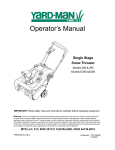
1
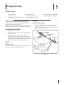
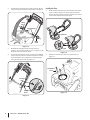
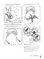
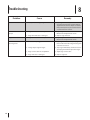
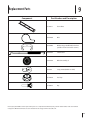
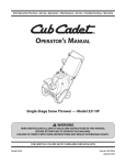
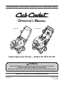
Safe Operation Practices • Set-Up • Operation • Maintenance • Service • Troubleshooting • Warranty
Operator’s Manual
Model 221 HP
Model 221 LHP
Single-Stage Snow Thrower — Models 221 HP & 221 LHP
WARNING
READ AND FOLLOW ALL SAFETY RULES AND INSTRUCTIONS IN THIS MANUAL
BEFORE ATTEMPTING TO OPERATE THIS MACHINE.
FAILURE TO COMPLY WITH THESE INSTRUCTIONS MAY RESULT IN PERSONAL INJURY.
CUB CADET LLC, P.O. BOX 361131 CLEVELAND, OHIO 44136-0019
Printed In USA
Form No. 769-08241
(June 6, 2012)
1
To The Owner
Thank You
Thank you for purchasing a Cub Cadet Snow Thrower. It was
carefully engineered to provide excellent performance when
properly operated and maintained.
If applicable, the power testing information used to establish
the power rating of the engine equipped on this machine can be
found at www.opei.org or the engine manufacturer’s web site.
Please read this entire manual prior to operating the equipment.
It instructs you how to safely and easily set up, operate and
maintain your machine. Please be sure that you, and any other
persons who will operate the machine, carefully follow the
recommended safety practices at all times. Failure to do so could
result in personal injury or property damage.
If you have any problems or questions concerning the machine,
phone your local Cub Cadet dealer or contact us directly. Cub
Cadet’s Customer Support telephone numbers, website address
and mailing address can be found on this page. We want to
ensure your complete satisfaction at all times.
All information in this manual is relative to the most recent
product information available at the time of printing. Review
this manual frequently to familiarize yourself with the machine,
its features and operation. Please be aware that this Operator’s
Manual may cover a range of product specifications for various
models. Characteristics and features discussed and/or illustrated
in this manual may not be applicable to all models. We reserve
the right to change product specifications, designs and
equipment without notice and without incurring obligation.
Throughout this manual, all references to right and left side of the
machine are observed from the operating position.
Table of Contents
Safe Operation Practices......................................... 3
Assembly & Set-Up................................................... 7
Controls & Features.................................................10
Operation.................................................................11
Maintenance & Adjustment..................................12
Service......................................................................14
Troubleshooting......................................................16
Replacement Parts..................................................17
Warranty................................................................. 20
Record Product Information
Model Number
Before setting up and operating your new equipment, please
locate the model plate on the equipment and record the
information in the provided area to the right. You can locate the
model plate by standing at the operator’s position and looking
down at the right rear of the snow thrower. This information will
be necessary, should you seek technical support via our web site,
Customer Support Department, or with a local authorized service
dealer.
Serial Number
Product Registration and Customer Support
Please register your product on our website, www.cubcadet.com.
If you have difficulty assembling this product or have any questions regarding the controls, operation, or maintenance of
this machine, you can seek help from the experts. Choose from the options below:
◊
Visit us on the web at www.cubcadet.com
See How-to Maintenance and Parts Installation Videos at www.cubcadet.com/tutorials
2
◊
Call a Customer Support Representative at (800) 965-4CUB
◊
Locate your nearest Cub Cadet Dealer at (877) 282-8684
◊
Write to Cub Cadet LLC • P.O. Box 361131 • Cleveland, OH • 44136-0019
Important Safe Operation Practices
2
WARNING! This symbol points out important safety instructions which, if not followed,
could endanger the personal safety and/or property of yourself and others. Read and follow
all instructions in this manual before attempting to operate this machine. Failure to comply
with these instructions may result in personal injury.
When you see this symbol. HEED ITS WARNING!
CALIFORNIA PROPOSITION 65
WARNING! Engine Exhaust, some of its constituents, and certain vehicle components
contain or emit chemicals known to State of California to cause cancer and birth defects
or other reproductive harm.
DANGER: This machine was built to be operated according to the safe operation practices in
this manual. As with any type of power equipment, carelessness or error on the part of the
operator can result in serious injury. This machine is capable of amputating fingers, hands,
toes and feet and throwing foreign objects. Failure to observe the following safety
instructions could result in serious injury or death.
Training
Preparation
1.
Read, understand, and follow all instructions on the
machine and in the manual(s) before attempting to
assemble and operate. Keep this manual in a safe place for
future and regular reference and for ordering replacement
parts.
Thoroughly inspect the area where the equipment is to be used.
Remove all doormats, newspapers, sleds, boards, wires and other
foreign objects, which could be tripped over or thrown by the
auger/impeller.
2.
Be familiar with all controls and their proper operation.
Know how to stop the machine and disengage them
quickly.
3.
1.
Always wear safety glasses or eye shields during operation
and while performing an adjustment or repair to protect
your eyes. Thrown objects which ricochet can cause serious
injury to the eyes.
Never allow children under 14 years of age to operate this
machine. Children 14 and over should read and understand
the instructions and safe operation practices in this manual
and on the machine and be trained and supervised by an
adult.
2.
Do not operate without wearing adequate winter outer
garments. Do not wear jewelry, long scarves or other loose
clothing, which could become entangled in moving parts.
Wear footwear which will improve footing on slippery
surfaces.
4.
Never allow adults to operate this machine without proper
instruction.
3.
Use a grounded three-wire extension cord and receptacle
for all machines with electric start engines.
5.
Thrown objects can cause serious personal injury. Plan
your snow-throwing pattern to avoid discharge of material
toward roads, bystanders and the like.
4.
Disengage all control levers before starting the engine.
5.
Never attempt to make any adjustments while engine is
running, except where specifically recommended in the
operator’s manual.
6.
Let engine and machine adjust to outdoor temperature
before starting to clear snow.
6.
7.
Keep bystanders, pets and children at least 75 feet from the
machine while it is in operation. Stop machine if anyone
enters the area.
Exercise caution to avoid slipping or falling, especially
when operating in reverse.
3
Safe Handling of Gasoline
5.
To avoid personal injury or property damage use extreme care
in handling gasoline. Gasoline is extremely flammable and the
vapors are explosive. Serious personal injury can occur when
gasoline is spilled on yourself or your clothes which can ignite.
Wash your skin and change clothes immediately.
Never run an engine indoors or in a poorly ventilated area.
Engine exhaust contains carbon monoxide, an odorless
and deadly gas.
6.
Do not operate machine while under the influence of
alcohol or drugs.
7.
Muffler and engine become hot and can cause a burn. Do
not touch. Keep children away.
a.
Use only an approved gasoline container.
b.
Extinguish all cigarettes, cigars, pipes and other
sources of ignition.
8.
Exercise extreme caution when operating on or crossing
gravel surfaces. Stay alert for hidden hazards or traffic.
c.
Never fuel machine indoors.
9.
d.
Never remove gas cap or add fuel while the engine is
hot or running.
Exercise caution when changing direction and while
operating on slopes. Do not operate on steep slopes.
10.
e.
Allow engine to cool at least two minutes before
refueling.
Plan your snow-throwing pattern to avoid discharge
towards windows, walls, cars etc. Thus, avoiding possible
property damage or personal injury caused by a ricochet.
f.
Never over fill fuel tank. Fill tank to no more than ½
inch below bottom of filler neck to provide space for
fuel expansion.
11.
Never direct discharge at children, bystanders and pets or
allow anyone in front of the machine.
12.
Do not overload machine capacity by attempting to clear
snow at too fast of a rate.
13.
Never operate this machine without good visibility or light.
Always be sure of your footing and keep a firm hold on the
handles. Walk, never run.
14.
Disengage power to the auger/impeller when transporting
or not in use.
15.
Never operate machine at high transport speeds on
slippery surfaces. Look down and behind and use care
when backing up.
g.
Replace gasoline cap and tighten securely.
h.
If gasoline is spilled, wipe it off the engine and
equipment. Move machine to another area. Wait 5
minutes before starting the engine.
i.
Never store the machine or fuel container inside
where there is an open flame, spark or pilot light
(e.g. furnace, water heater, space heater, clothes
dryer etc.).
j.
Allow machine to cool at least 5 minutes before
storing.
16.
k.
Never fill containers inside a vehicle or on a truck
or trailer bed with a plastic liner. Always place
containers on the ground away from your vehicle
before filling.
If the machine should start to vibrate abnormally, stop
the engine, disconnect the spark plug wire and ground it
against the engine. Inspect thoroughly for damage. Repair
any damage before starting and operating.
17.
If possible, remove gas-powered equipment from
the truck or trailer and refuel it on the ground. If this
is not possible, then refuel such equipment on a
trailer with a portable container, rather than from a
gasoline dispenser nozzle.
Disengage all control levers and stop engine before you
leave the operating position (behind the handles). Wait
until the auger/impeller comes to a complete stop before
unclogging the chute assembly, making any adjustments,
or inspections.
18.
Never put your hand in the discharge or collector openings.
Do not unclog chute assembly while engine is running.
Shut off engine and remain behind handles until all moving
parts have stopped before unclogging.
19.
Use only attachments and accessories approved by the
manufacturer (e.g. wheel weights, tire chains, cabs etc.).
20.
When starting engine, pull cord slowly until resistance
is felt, then pull rapidly. Rapid retraction of starter cord
(kickback) will pull hand and arm toward engine faster than
you can let go. Broken bones, fractures, bruises or sprains
could result.
21.
If situations occur which are not covered in this manual, use
care and good judgment. Contact Customer Support for
assistance and the name of your nearest servicing dealer.
l.
m. Keep the nozzle in contact with the rim of the fuel
tank or container opening at all times until fueling is
complete. Do not use a nozzle lock-open device.
Operation
4
1.
Do not put hands or feet near rotating parts, in the auger/
impeller housing or chute assembly. Contact with the
rotating parts can amputate hands and feet.
2.
The auger/impeller control lever is a safety device. Never
bypass its operation. Doing so makes the machine unsafe
and may cause personal injury.
3.
The control levers must operate easily in both directions
and automatically return to the disengaged position when
released.
4.
Never operate with a missing or damaged chute assembly.
Keep all safety devices in place and working.
Section 2 — Important Safe Operation Practices
Clearing a Clogged Discharge Chute
Hand contact with the rotating impeller inside the discharge
chute is the most common cause of injury associated with snow
throwers. Never use your hand to clean out the discharge chute.
To clear the chute:
1.
SHUT THE ENGINE OFF!
2.
Wait 10 seconds to be sure the impeller blades have
stopped rotating.
3.
Always use a clean-out tool, not your hands.
Maintenance & Storage
1.
Never tamper with safety devices. Check their proper
operation regularly. Refer to the maintenance and
adjustment sections of this manual.
2.
Before cleaning, repairing, or inspecting machine
disengage all control levers and stop the engine. Wait until
the auger/impeller come to a complete stop. Disconnect
the spark plug wire and ground against the engine to
prevent unintended starting.
3.
Check bolts and screws for proper tightness at frequent
intervals to keep the machine in safe working condition.
Also, visually inspect machine for any damage.
4.
Do not change the engine governor setting or over-speed
the engine. The governor controls the maximum safe
operating speed of the engine.
5.
Snow thrower shave plates and skid shoes are subject to
wear and damage. For your safety protection, frequently
check all components and replace with original equipment
manufacturer’s (OEM) parts only. “Use of parts which do
not meet the original equipment specifications may lead to
improper performance and compromise safety!”
6.
Check control levers periodically to verify they engage
and disengage properly and adjust, if necessary. Refer
to the adjustment section in this operator’s manual for
instructions.
7.
Maintain or replace safety and instruction labels, as
necessary.
8.
Observe proper disposal laws and regulations for gas, oil,
etc. to protect the environment.
9.
Prior to storing, run machine a few minutes to clear snow
from machine and prevent freeze up of auger/impeller.
10.
Never store the machine or fuel container inside where
there is an open flame, spark or pilot light such as a water
heater, furnace, clothes dryer etc.
11.
Always refer to the operator’s manual for proper
instructions on off-season storage.
12.
Check fuel line, tank, cap, and fittings frequently for cracks
or leaks. Replace if necessary.
13.
Do not crank engine with spark plug removed.
14.
According to the Consumer Products Safety Commission
(CPSC) and the U.S. Environmental Protection Agency (EPA),
this product has an Average Useful Life of seven (7) years,
or 60 hours of operation. At the end of the Average Useful
Life have the machine inspected annually by an authorized
service dealer to ensure that all mechanical and safety
systems are working properly and not worn excessively.
Failure to do so can result in accidents, injuries or death.
Do not modify engine
To avoid serious injury or death, do not modify engine in any
way. Tampering with the governor setting can lead to a runaway
engine and cause it to operate at unsafe speeds. Never tamper
with factory setting of engine governor.
Notice Regarding Emissions
Engines which are certified to comply with California and federal
EPA emission regulations for SORE (Small Off Road Equipment)
are certified to operate on regular unleaded gasoline, and
may include the following emission control systems: Engine
Modification (EM), Oxidizing Catalyst (OC), Secondary Air
Injection (SAI) and Three Way Catalyst (TWC) if so equipped.
Spark Arrestor
WARNING! This machine is equipped with an
internal combustion engine and should not be used
on or near any unimproved forest-covered, brush
covered or grass-covered land unless the engine’s
exhaust system is equipped with a spark arrestor
meeting applicable local or state laws (if any).
If a spark arrestor is used, it should be maintained in effective
working order by the operator. In the State of California the
above is required by law (Section 4442 of the California Public
Resources Code). Other states may have similar laws. Federal laws
apply on federal lands.
A spark arrestor for the muffler is available through your
nearest engine authorized service dealer or contact the service
department, P.O. Box 361131 Cleveland, Ohio 44136-0019.
Section 2 — Important Safe Operation Practices
5
Safety Symbols
This page depicts and describes safety symbols that may appear on this product. Read, understand, and follow all instructions on the
machine before attempting to assemble and operate.
Symbol
Description
READ THE OPERATOR’S MANUAL(S)
Read, understand, and follow all instructions in the manual(s) before attempting to
assemble and operate
WARNING— ROTATING BLADES
Keep hands out of inlet and discharge openings while machine is running. There are rotating
blades inside
WARNING— ROTATING BLADES
Keep hands out of inlet and discharge openings while machine is running. There are rotating
blades inside
WARNING— ROTATING AUGER
Do not put hands or feet near rotating parts, in the auger/impeller housing or chute
assembly. Contact with the rotating parts can amputate hands and feet.
WARNING—THROWN OBJECTS
This machine may pick up and throw and objects which can cause serious personal injury.
WARNING—GASOLINE IS FLAMMABLE
Allow the engine to cool at least two minutes before refueling.
WARNING— CARBON MONOXIDE
Never run an engine indoors or in a poorly ventilated area. Engine exhaust contains carbon
monoxide, an odorless and deadly gas.
WARNING— ELECTRICAL SHOCK
Do not use the engine’s electric starter in the rain
WARNING— HOT SURFACE
Engine parts, especially the muffler, become extremely hot during operation. Allow engine
and muffler to cool before touching.
WARNING! Your Responsibility—Restrict the use of this power machine to persons who read, understand and
follow the warnings and instructions in this manual and on the machine.
SAVE THESE INSTRUCTIONS!
6
Section 2 — Important Safe Operation Practices
3
Assembly & Set-Up
Contents of Carton
•
One Snow Thrower
•
One Chute Assembly
•
One Chute Rotation Control Assembly
•
Two Ignition Keys
•
One 20 oz. Bottle 5W-30 Oil
•
One Electric Starter Cord (If equipped)
•
One Snow Thrower Operator’s Manual •
One Engine Operator’s Manual
NOTE: This Operator’s Manual covers several models. Snow
thrower features may vary by model. Not all features in this
manual are applicable to all snow thrower models and the snow
thrower depicted may differ from yours.
NOTE: All references to the left or right side of the snow thrower
are from the operator’s position. Any exceptions will be noted.
Unpacking the Snow Thrower
1.
Open the top of the carton.
2.
Cut down the corners on the front of the carton and fold
down the front side.
3.
Pull the snow thrower out of the carton. Be sure not to
damage the chute, chute rotation control assembly or any
cables attached to the chute. Some of these parts are shipped
under the shroud on the backside of the carton. Check for any
cable ties securing the chute and remove if necessary.
Assembly
Positioning the Upper Handle
1.
Remove the wing knob and carriage bolt from the top
of the lower handle. See Figure 3-1. It is not necessary to
remove the shoulder screw and flange lock nut below the
wing knob and carriage bolt.
Wing Knob
Carriage Bolts
Wing Knob
Set-Up
Adding Fuel & Oil
Refer to the Engine Operator’s Manual packed with your snow
thrower for information on adding fuel and oil.
Figure 3-1
7
2.
Pivot the upper handle into the operating position. Be sure
not to pinch any of the cables in the process. See Figure 3-2.
Installing the Chute
1.
On the 221 HP model place the chute handle on the lower
chute as shown in Figure 3-4. Skip to step 2 for 221 LHP
models. Be certain that the handle is aligned in the channel
on the chute and the tabs snap into place.
Wing
Knob
Carriage Bolts
Channel
Wing
Knob
Figure 3-2
3.
4.
Tab
On model 221 HP, tighten the previously removed
hardware to secure the handle in place. See Figure 3-2. On
model 221 LHP proceed with step 4.
The handle on model 221 LHP can be set in three different
position. Place the handle in the desired position and then
install wing knobs and carriage bolts in the appropriate
hole and secure the handle. See Figure 3-3.
Figure 3-4
2.
Remove the hex washer screws in the chute base. See
Figure 3-5.
Hex Washer
Screw
Carriage
Bolt
Wing
Knob
Figure 3-3
8
Section 3— Assembly & Set-Up
Figure 3-5
3.
Align the holes in the chute base with the holes in the
lower chute and secure with the previously removed hex
washer screws. See Figure 3-6.
Figure 3-6
2.
Using the four hex washer screws, install the chute rotation
control assembly. See Figure 3-8.
3.
Remove the screw and hex lock nut from the universal
joint. See Figure 3-9.
Figure 3-8
Installing the Chute Rotation Control Assembly (Model 221 LHP only)
1.
Remove the four hex washer screws from the back of the
handle (two on each side). See Figure 3-7.
Universal Joint
Hex Lock Nut
Screw
Hex Lock Nut
Chute Rod
Screw
Figure 3-9
NOTE: Make sure the chute is facing forward when
installing the universal joint.
Figure 3-7
4.
Install the universal joint on the end of the chute rod as
shown in Figure 3-9.
NOTE: Be sure the holes in the universal joint line up with
the holes in the chute rod. You may have to activate the
trigger to allow you to line up the holes.
5.
Secure the universal joint with the hex nut and screw
previously removed. See Figure 3-9.
Section 3 — Assembly & Set-Up
9
6.
Slide the rubber bellow over the universal joint. See Figure
3-10.
Rubber Bellow
Figure 3-10
Installing the Recoil Starter Handle
1.
Remove the eye bolt and handle knob from the manual bag.
2.
Place the eye bolt and handle knob on the upper handle
as shown in Figure 3-11. Do not fully tighten the hardware
until instructed to do so.
Recoil Starter Handle
Eye Bolt
Handle
Knob
Figure 3-11
NOTE: The opening of the eye bolt should face toward the
back of the snow thrower.
10
3.
Slowly pull the recoil starter handle up towards the eye
bolt.
4.
Slip the recoil starter rope into the eye bolt from the back
of the snow thrower. See Figure 3-11.
5.
Securely tighten the eye bolt and handle knob.
Section 3— Assembly & Set-Up
4
Controls & Features
Headlight
Chute Tilt Control
Auger Control
Recoil Starter Handle
Chute Rotation Control
Chute Assembly
Auger
Shave Plate
NOTE: This Operator’s Manual covers several models. Snow
thrower features may vary by model. Not all features in this
manual are applicable to all snow thrower models and the snow
thrower depicted may differ from yours.
Chute Tilt Control (Model 221 LHP)
NOTE: All references to the left or right side of the snow thrower
are from the operator’s position. Any exceptions will be noted.
The chute tilt control is located to the right of the control panel
and controls the angle/distance that snow is thrown. Pull back
on the chute tilt control to increase the angle/distance and push
forward to decrease the angle/distance.
Headlight (Model 221 LHP)
Chute Rotation Control (Model 221 LHP)
The headlight is located on the upper center of the control panel
and is on when the snow thrower is running.
Recoil Starter Handle
The chute rotate control is located in the center of the control panel
and controls the direction snow is thrown. Depress the button and
rotate the chute rotation control to the right to turn the chute to the
right and rotate to the left to turn the chute to the left.
The recoil starter handle is used to manually start the engine.
Auger
EZ Chute (Model 221 HP)
When engaged, the auger rotation draws snow into the auger
housing and throws it out the discharge chute. Rubber paddles
on the auger also aid in propelling the snow thrower as they
come in contact with the pavement.
The rotation of the chute is controlled by rotating the chute control
handle left or right. The angle/distance that snow is thrown is
changed by manually tilting the upper chute to the desired position.
Shave Plate
The shave plate maintains contact with the pavement as
the snow thrower is propelled, allowing snow close to the
pavement’s surface to be discharged.
Auger Control
Located on the upper handle, the auger control is used to engage
and disengage drive to the auger. Squeeze the control against the
upper handle to engage the auger; release it to disengage.
11
5
Operation
NOTE: Refer to the Engine Operator’s Manual for instruction on
starting, stopping and operating the engine.
Engaging the Auger
1.
To engage the auger and start throwing snow, squeeze the
auger control against the handle. Release to stop the auger.
See Figure 5-1.
Chute Controls (Model 221 LHP)
Refer to Figure 5-2 for chute controls.
Chute Tilt Control
Chute Rotation
Control
Auger
Control
Handle
Figure 5-2
To increase the angle/distance snow is thrown, pull up/back on
the chute tilt control. To decrease the angle/distance snow is
thrown, push down/forward on the chute tilt control.
Figure 5-1
Engaging the Drive
Lift up slightly on the handle to allow the rubber paddles on the
auger to contact the pavement and propel the snow thrower
forward. Pushing downward on the handle will raise the auger
off the ground and stop the forward motion.
NOTE: Excessive upward pressure on the handle will result
in premature wear on the rubber auger blades which will
not be covered by the warranty.
Clearing a Clogged Discharge Chute
WARNING! Never use your hands to clear a
clogged chute assembly. Shut off engine and remain
behind handles until all moving parts have stopped
before using the clean-out tool to clear the chute
assembly.
Hand contact with the rotating impeller inside the discharge
chute is the most common cause of injury associated with snow
throwers. Never use your hand to clean out the discharge chute.
To clear the chute:
12
1.
SHUT THE ENGINE OFF!
2.
Wait 10 seconds to be sure the impeller blades have
stopped rotating.
3.
Always use a clean-out tool or stick, not your hands.
To rotate the chute to the left, pull the trigger and turn the chute
rotation control to the left. To rotate the chute to the right, pull
the trigger and turn the chute rotation control to the right.
Chute Control (Model 221 HP)
Refer to Figure 5-3 for the chute controls.
Chute Control
Handle
Upper
Chute
Wing Nut
Figure 5-3
To increase the angle/distance snow is thrown, pull up/back on
the upper chute. To decrease the angle/distance snow is thrown,
push down/forward on the upper chute.
To rotate the chute to the left, turn the chute control handle to
the right. To rotate the chute to the right, turn the chute control
handle to the left.
Section 5 — Operation
13
6
Maintenance & Adjustments
Adjustments
Control Cable
WARNING! Before servicing, repairing or
inspecting the snow thrower, disengage the auger
control. Stop the engine and remove the key to
prevent unintended starting.
Shave Plate
To check the adjustment of the shave plate, place the snow
thrower on a level surface. The wheels, shave plate and auger
should all contact the level surface. Note that if the shave plate is
adjusted too high, snow may blow under the housing. If the shave
plate wears out excessively, or the snow thrower does not selfpropel, the shave plate may be too low and needs to be adjusted.
As a result of both the control cable and the auger drive belt
stretching due to wear, periodic adjustments may be necessary. If
the auger seems to hesitate when rotating, proceed as follows:
The upper hole in the control handle provides for an adjustment in
cable tension. To adjust, disconnect the end of control cable from
the bottom hole in the control handle and reinsert it in the upper
hole. Insert the cable from the outside as shown in Figure 6-2.
Auger Control Handle
NOTE: On new snow throwers or machines with a new shave
plate installed, the auger may be slightly off the ground.
To adjust the shave plate proceed as follows:
1.
Run the snow thrower until the fuel tank is empty.
2.
Pull the recoil starter handle until resistance is felt. Then tip
the snow thrower back until it rests on the handles.
3.
Loosen the four flange lock nuts and carriage screws which
secure the shave plate to the housing. See Figure 6-1. Move
the shave plate to the desired position and retighten the
nuts and bolts securely.
Side View
Carriage Screw
Flange Lock Nut
Reversible Shave Plate
Figure 6-1
4.
Tip the snow thrower back to the operating position and pull
the starter handle a few times to see if it is difficult to pull.
5.
If the starter is difficult to pull, remove the spark plug and
pull the handle several times to ensure that any oil trapped
in the head is removed.
CAUTION: Oil may come out of the spark plug hole
when it is removed and the starter handle is pulled.
14
6.
Inspect the spark plug. If it is wet, clean off any oil before
re-installing.
Control Cable
Figure 6-2
Test the snow thrower to see if there is a noticeable difference. If after
the adjustment to the control cable the auger still hesitates when
rotating, see the Service section for instructions on replacing the belt.
Maintenance
5.
Off-Season Storage
Tip the snow thrower back to the operating position and pull
the starter handle a few times to see if it is difficult to pull.
6.
If the starter is difficult to pull, remove the spark plug and
pull the handle several times to ensure that any oil trapped
in the head is removed.
If the snow thrower will not be used for 30 days or longer, follow
the instructions below.
1.
Store the equipment in a clean, dry area.
2.
If storing the snow thrower in an unventilated area,
rustproof the machine using a light oil or silicone to coat
the snow thrower.
3.
Clean the exterior of the engine and the snow thrower.
4.
Lubricate pivot points on control handle and extension
spring at end of control cable with a light oil.
CAUTION: Oil may come out of the spark plug hole
when it is removed and the starter handle is pulled.
7.
Inspect the spark plug. If it is wet, clean off any oil before
re-installing.
Engine
Refer to the Engine Operators manual packed separately with
your snow thrower for maintenance and adjustment information
on your engine.
1.
To access the oil drain and spark plug it is necessary to
remove the lower panel.
2.
Remove the three screws that secure the lower panel.
Remove the lower panel by lifting up on the panel to free
the tabs at the bottom of the panel from the tab slots and
then pull back. See Figure 6-3.
Figure 6-3
NOTE: The bottom of the panel has tabs that help hold it in
place.
NOTE: An oil drain extension kit is available separately.
Contact your local Cub Cadet dealer or contact Cub Cadet’s
Customer Support for kit #753-06684.
3.
Change the oil and/or the spark plug as instructed in your
Engine Operator’s manual.
4.
Re-install the lower panel by placing the tabs in the tab
slots, lifting the panel into place and secure with the three
screws removed in step 2.
Section 6 — Maintenance & Adjustments
15
7
Service
Replacing Belt
1.
Run the snow thrower until the fuel tank is empty.
2.
Pull the recoil starter handle until resistance is felt. Then tip
the snow thrower back until it rests on the handles.
3.
Slide a board up through the auger and through the chute
to secure the auger in place.
4.
Remove the belt cover by removing the three hex washer
screws and one hex lock screw that secure it to the frame.
See Figure 7-1.
Hex Lock Screw
To replace the belt follow these instructions and refer to Figure
7-3:
Drive Pulley
Idler Pulley
Belt Keeper
Flange Nut
Auger Pulley
Figure 7-3
NOTE: Installing the belt and belt cover may be easier if the
auger control is squeezed against the upper handle.
Hex Washer Screw
1.
Route the belt around the drive pulley and under the idler
pulley. See Figure 7-3.
2.
Route the end of the belt around the auger pulley and slide
the pulley back on to the auger shaft. It may be necessary
to push down on the idler pulley to get the auger pulley
under the belt keeper.
3.
Replace the flange nut and tighten securely.
4.
Reinstall the belt cover removed earlier.
5.
Remove the board from the auger and chute.
6.
Tip the snow thrower back to the operating position and pull
the starter handle a few times to see if it is difficult to pull.
7.
If the starter is difficult to pull, remove the spark plug and
pull the handle several times to ensure that any oil trapped
in the head is removed.
Figure 7-1
5.
Remove the flange nut that secures the auger pulley to the
auger shaft. See Figure 7-2.
CAUTION: Oil may come out of the spark plug hole
when it is removed and the starter handle is pulled.
8.
Flange Nut
Auger Shaft
Auger Pulley
Figure 7-2
16
6.
Remove the auger pulley and the belt.
Inspect the spark plug. If it is wet, clean off any oil before
re-installing.
Replacing Auger Paddles
Replacing Shave Plate
The snow thrower auger’s rubber paddles are subject to wear
and should be replaced if any signs of excessive wear are present.
The shave plate is attached to the bottom of the auger housing
and is subject to wear. It should be checked periodically. There
are two wearing edges and the shave plate can be reversed.
CAUTION: Do NOT allow the auger’s rubber
paddles to wear to the point where portions of the
metal auger itself can come in contact with the
pavement. Doing so can result in serious damage to
your snow thrower.
To change the rubber paddles, proceed as follows:
1.
1.
Run the snow thrower until the fuel tank is empty.
2.
Pull the recoil starter handle until resistance is felt. Then tip
the snow thrower back until it rests on the handles.
3.
Remove the four carriage screws and flange lock nuts
which attach it to the snow thrower housing. See Figure
7-5.
Remove the existing rubber paddles by unthreading the hex
washer screws which secure them to the auger. See Figure 7-4.
Side View
Auger Paddle
Carriage Screw
Hex Washer Screw
Flange Lock Nut
Reversible Shave Plate
Hex Washer Screw
Figure 7-4
NOTE: The auger paddles should be replaced one-at-a-time
so that the auger still attached can be used as an example for
positioning and re-installing the new auger.
2.
Secure the replacement rubber paddles to the auger using
the hardware removed earlier.
Figure 7-5
4.
Install the new shave plate, making sure the heads of the
carriage bolts are on the inside of the housing.
5.
Adjust the shave plate as instructed in the Maintenance &
Adjustments section.
6.
Tighten securely once adjusted.
Engine
Refer to the Engine Operators manual packed separately with
your snow thrower for service information for your engine.
Section 7 — Service
17
8
Troubleshooting
Problem
18
Cause
Remedy
Excessive vibration
1. Loose parts or damaged auger.
1. Stop engine immediately and disconnect
spark plug wire. Check for possible damage.
Tighten all bolts and nuts. Repair as needed.
If the problem persists, take snow thrower to
an authorized service dealer.
Snow thrower fails to selfpropel
1. Auger control cable out of adjustment.
1. Adjust auger control cable as shown in
Maintenance & Adjustments section.
2. Auger drive belt loose or damaged.
2. Replace auger drive belt.
Augers continue to rotate
1. Auger control cable out of adjustment.
1. Adjust auger control cable as shown in
Maintenance & Adjustments section.
Snow thrower fails to
discharge snow
1. Chute assembly clogged.
1. Stop engine and disconnect spark plug wire.
Clean chute and inside of auger housing with
clean-out tool or stick.
2. Foreign object lodged in auger.
2. Stop engine immediately and disconnect the
spark plug wire. Remove object from auger.
3. Auger control cable out of adjustment.
3. Adjust auger control cable.
4. Auger belt loose or damaged.
4. Replace auger belt.
9
Replacement Parts
Component
Part Number and Description
731-08171
Shave Plate
954-04050Belt
753-06469
Rubber Auger Paddle Kit (Includes 2
paddles and 12 hex washer screws)
746-04701
Clutch Cable
634-04347
Wheel Assembly, 8”
925-1629
Lamp, #1156 (Model 221 LHP)
751-14006
Fuel Cap
731-05632
Key
Phone (800) 965-4CUB to order replacement parts or a complete Parts Manual (have your full model number and serial number
ready). Parts Manual downloads are also available free of charge at www.cubcadet.com.
19
CUB CADET LLC
MANUFACTURER’S LIMITED WARRANTY FOR
SNOW THROWERS, CHIPPER-SHREDDERS, CHIPPER-SHREDDER VACUUMS,
LOG SPLITTERS AND JET SWEEPS
The limited warranty set forth below is given by Cub Cadet LLC with
respect to new merchandise purchased and used in the United States,
its possessions and territories, and by MTD Products Limited with
respect to new merchandise purchased and used in Canada and/or its
territories and possessions.
This warranty is in addition to any applicable emissions warranty
provided with your product.
For non-commercial use: Cub Cadet warrants this product (excluding
Normal Wear Parts, as described below) against defects in material
and workmanship for a period of three (3) years from the date of
original retail purchase or lease.
For commercial uses and applications: Cub Cadet warrants this
product (excluding Normal Wear Parts, as described below) against
defects in material and workmanship for a period of one (1) year from
the date of original retail purchase or lease.
“Cub Cadet” will, at its option, repair or replace, free of charge, any
part found to be defective in materials or workmanship. This limited
warranty shall only apply if this product has been operated and
maintained in accordance with the Operator’s Manual furnished with
the product, and has not been subject to misuse, abuse, neglect,
accident, improper maintenance, alteration, vandalism, theft, fire,
water, or damage because of other peril or natural disaster. Damage
resulting from the installation or use of any part, accessory or
attachment not approved by Cub Cadet for use with the product(s)
covered by this manual will void your warranty as to any resulting
damage.
Normal Wear Parts are warranted to be free from defects in material
and workmanship for a period of thirty (30) days from the date of
purchase. Normal wear parts include, but are not limited to items
such as: belts, skid shoes, shave plates, blades, debris collection
bags, wheels and tires.
HOW TO OBTAIN SERVICE: Warranty service is available, WITH
PROOF OF PURCHASE, through your local authorized service
dealer. To locate the dealer in your area:
In the U.S.A.
To locate the dealer in your area, check your Yellow Pages, or contact
Cub Cadet LLC at P.O. Box 361131, Cleveland, Ohio 44136-0019, or
call 1-877-282-8684, or log on to our Web site at www.cubcadet.
com.
In Canada
Contact MTD Products Limited, Kitchener, ON N2G 4J1, or call
1-800-668-1238 or log on to our Web site at www.mtdcanada.
com.
b. Log splitter pumps, valves, and cylinders have a separate one year
warranty.
c. Cub Cadet does not extend any warranty for products sold or
exported outside of the United States and/or Canada, and their
respective possessions and territories, except those sold through
Cub Cadet’s authorized channels of export distribution.
d. Replacement parts that are not genuine Cub Cadet parts.
e. Service completed by someone other than an authorized service
dealer.
f. Transportation charges and service calls.
No implied warranty, including any implied warranty of merchantability of fitness for a particular purpose, applies after the
applicable period of express written warranty above as to the parts
as identified. No other express warranty, whether written or oral,
except as mentioned above, given by any person or entity, including a dealer or retailer, with respect to any product, shall bind Cub
Cadet. During the period of the warranty, the exclusive remedy is
repair or replacement of the product as set forth above.
The provisions as set forth in this warranty provide the sole and
exclusive remedy arising from the sale. Cub Cadet shall not be
liable for incidental or consequential loss or damage including,
without limitation, expenses incurred for substitute or replacement
lawn care services or for rental expenses to temporarily replace a
warranted product.
Some states do not allow the exclusion or limitation of incidental
or consequential damages, or limitations on how long an implied
warranty lasts, so the above exclusions or limitations may not apply
to you.
In no event shall recovery of any kind be greater than the amount of
the purchase price of the product sold. Alteration of safety features
of the product shall void this warranty. You assume the risk and
liability for loss, damage, or injury to you and your property and/or to
others and their property arising out of the misuse or inability to use
the product.
This limited warranty shall not extend to anyone other than the
original purchaser or to the person for whom it was purchased as a
gift.
HOW STATE LAW RELATES TO THIS WARRANTY: This limited
warranty gives you specific legal rights, and you may also have other
rights that vary in different jurisdictions.
IMPORTANT: Owner must present Original Proof of Purchase to
obtain warranty coverage.
This limited warranty does not provide coverage in the following
cases:
a. Routine maintenance items such as lubricants, filters, blade
sharpening, tune-ups, brake adjustments, clutch adjustments,
deck adjustments, and normal deterioration of the exterior finish
due to use or exposure.
Cub Cadet LLC, P.O. BOX 361131 CLEVELAND, OHIO 44136-0019; Phone: 1-877-282-8684
MTD Canada Limited - KITCHENER, ON N2G 4J1; Phone 1-800-668-1238
GDOC-100160 REV. B