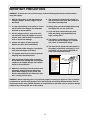
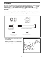
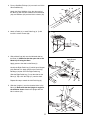
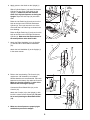
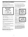
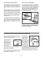
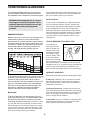
1
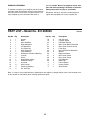
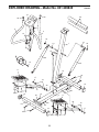
¨
Model No. 831.285840
Serial No
The serial number is found in the
location shown below. Write the
serial number in the space above.
Serial
Number
Decal
CAUTION
Read all precautions and
instructions in this manual
before using this equipment.
Keep this manual for future
reference.
USERÕS MANUAL
SEARS, ROEBUCK AND CO., HOFFMAN ESTATES, IL 60179
TABLE OF CONTENTS
BEFORE YOU BEGIN . . . . . . . . . . . . . . . . . . . . . . . . . . . . . . . . . . . . . . . . . . . . . . . . . . . . . . . . . . . . . . . . . . .2
IMPORTANT PRECAUTIONS . . . . . . . . . . . . . . . . . . . . . . . . . . . . . . . . . . . . . . . . . . . . . . . . . . . . . . . . . . . . .3
ASSEMBLY . . . . . . . . . . . . . . . . . . . . . . . . . . . . . . . . . . . . . . . . . . . . . . . . . . . . . . . . . . . . . . . . . . . . . . . . . . .4
HOW TO USE THE STEPPER . . . . . . . . . . . . . . . . . . . . . . . . . . . . . . . . . . . . . . . . . . . . . . . . . . . . . . . . . . . . .6
STORAGE AND TROUBLE-SHOOTING . . . . . . . . . . . . . . . . . . . . . . . . . . . . . . . . . . . . . . . . . . . . . . . . . . . . .7
CONDITIONING GUIDELINES . . . . . . . . . . . . . . . . . . . . . . . . . . . . . . . . . . . . . . . . . . . . . . . . . . . . . . . . . . . . .9
PART LIST . . . . . . . . . . . . . . . . . . . . . . . . . . . . . . . . . . . . . . . . . . . . . . . . . . . . . . . . . . . . . . . . . . . . . . . . . . .10
EXPLODED DRAWING . . . . . . . . . . . . . . . . . . . . . . . . . . . . . . . . . . . . . . . . . . . . . . . . . . . . . . . . . . . . . . . . .11
HOW TO ORDER REPLACEMENT PARTS . . . . . . . . . . . . . . . . . . . . . . . . . . . . . . . . . . . . . . . . . . .Back Cover
FULL 90 DAY WARRANTY . . . . . . . . . . . . . . . . . . . . . . . . . . . . . . . . . . . . . . . . . . . . . . . . . . . . . . .Back Cover
BEFORE YOU BEGIN
Thank you for selecting the new PROFORM¨ 220C
stepper. The 220C stepper blends advanced engineering with contemporary styling to provide you with
a low-impact workout in the convenience and privacy
of your own home.
HELPLINE at 1-800-736-6879, Monday through
Saturday, 7 a.m. until 7 p.m. Central Time (excluding
holidays). To help us assist you, please mention the
product model number and serial number when calling. The model number is 831.285840. The serial
number can be found on a decal attached to the
PROFORM 220C (see the front cover of this manual
for the location of the decal).
For your benefit, read this manual carefully before
you use the PROFORM¨ 220C. If you have questions
after reading the manual, please call our toll-free
2
IMPORTANT PRECAUTIONS
WARNING: To reduce the risk of serious injury, read the following important precautions before
using the stepper.
1. Read all instructions in this manual before
using the stepper. Use the stepper only as
described.
9. The resistance cylinders may become hot
after a period of use. Allow the cylinders to
cool before touching them
2. It is the responsibility of the owner to ensure
that all users of the stepper are adequately
informed of all precautions.
10. Always keep your back straight when using
the stepper. Do not arch your back.
11. If you feel pain or dizziness at any time
while exercising, stop immediately and
begin cooling down.
3. Use the stepper indoors, away from moisture and dust. Place the stepper on a level
surface, with a mat beneath it to protect the
floor or carpet from damage.
12. The stepper is intended for in-home use
only. Do not use the stepper in a commercial, rental, or institutional setting.
4. Inspect and tighten all parts regularly.
Replace any worn parts immediately.
13. The decal shown below has been placed on
the stepper. If the decal is missing, or if it is
not legible, call our toll-free HELPLINE to
order a free replacement decal.
5. Keep children under the age of 12 and pets
away from the stepper at all times.
6. The stepper should not be used by persons
weighing more than 250 pounds.
! WARNING
7. Wear appropriate clothing when exercising;
do not wear loose clothing that could become
caught on the stepper. Always wear athletic
shoes for foot protection.
• Misuse of this product
may result in serious
injury.
• Read user’s manual
and follow all warnings
and operating instructions prior to use.
• Do not allow children
on or around machine.
• Replace label if
damaged, illegible, or
removed.
8. Maintain a continuous, smooth motion when
exercising. Always keep your feet on the
pedals when stepping, or the pedals may
become separated from the resistance cylinders, causing serious injury.
WARNING: Before beginning this or any exercise program, consult your physician. This is especially important for persons over the age of 35 or persons with pre-existing health problems. Read all
instructions before using. SEARS assumes no responsibility for personal injury or property damage
sustained by or through the use of this product.
3
ASSEMBLY
Place all parts of the stepper in a cleared area and remove the packing materials. Do not dispose of the packing
materials until assembly is completed. Assembly requires the included allen wrench
, a phillips
screwdriver
, two adjustable wrenches
and a rubber mallet
.
PART CHART
Use the drawings below to identify the small parts used in assembly. The number in parenthesis below each
drawing refers to the key number of the part, from the PART LIST on page 10. The second number refers to the
quantity used in assembly. Note: If a part is not found in the parts bag, check to see if it has been
preassembled.
M10 Locknut (15)Ð8
M8 x 19mm Button
Head Bolt (21)Ð4
Washer (25)Ð4
M10 x 82mm Carriage Bolt (24)Ð4
M4 x 12mm Console
Screw (22)Ð4
M4 x 10mm Screw (28)Ñ8
1. Press a Stabilizer Endcap (13) onto each end of the
Long Stabilizer (8).
Attach the Long Stabilizer (8) to the indicated end of
the Base (2) with two M10 x 65mm Hex Head Bolts
(24), two Washers (25) and two M10 Locknuts (15).
1
13
15
8
15
25
24
4
2
25
13
2. Press a Stabilizer Endcap (13) onto each end of the
Short Stabilizer (3).
2
Attach the Short Stabilizer (3) to the other end of
the Base (2) with two M10 x 65mm Hex Head Bolts
(24), two Washers (25) and two M10 Locknuts (15).
25
3
13
24
15
25
2
13
15
3. Attach a Pedal (11) to each Pedal Leg (6, 7) with
four M4 x 10mm Screws (28).
3
11
6
28
4. Slide a Metal Cap (30) onto the indicated shaft on
the Base (2). Make sure that the open side of the
Metal Cap is facing the Base.
4
Apply Grease
to Shaft
6
Apply grease to the shaft on the Base (2).
Identify the Right Pedal Leg (7) which has a Magnet
(26) attached to it. Apply grease to the Pedal Leg
Bushings (16) that are in the Right Pedal Leg.
30
Slide the Right Pedal Leg (7) onto the shaft on the
Base (2). Tap a 3/4Ó Axle Cap (17) onto the shaft.
Apply
Grease
26
2
7
Repeat this step to attach the Left Pedal Leg (6).
5. Slide the Upright (1) onto the threaded bolts in the
Base (2). Make sure that the Upright is angled in
the direction shown. Attach the Upright with four
M10 Locknuts (15).
5
15
1
15
2
5
16
17
6. Apply grease to the shafts on the Upright (1).
6
18 19
Slide a Cylinder Spacer (19) and a Resistance
Cylinder (9) onto each of the shafts on the
Upright (1). Make sure that the indented
sides of the Cylinder Spacers are facing the
Upright. Tap a 5/8Ó Axle Cap (18) onto each
shaft.
Apply
Grease
19
18
Slots
1
Raise the Left Pedal Leg (6) and rest it on the
hook at the lower end of the left Resistance
Cylinder (9). The hook must be in one of the
slots under the Left Pedal Leg as shown in the
inset drawing.
9
6
Raise the Right Pedal Leg (7) and rest it on the
hook at the lower end of the right Resistance
Cylinder (9). Make sure that the hooks are in
the same position under both Pedals.
9
7
7. Attach the Right Handlebar (4) to the Upright
(1) with two M6 x 12mm Button Head Bolts
(21).
7
5
21
Attach the Left Handlebar (5) to the Upright (1)
in the same manner.
4
1
8. Refer to the inset drawing. The Console (10)
requires two ÒAAÓ batteries (not included).
Alkaline batteries are recommended. Press two
batteries into the battery clip under the Console.
Make sure that the negative (Ð) ends of the
batteries are touching the springs.
8
Batteries
10
Connect the Reed Switch Wire (12) to the
Console (10).
10
Attach the Console (10) to the Upright (1) with
four M4 x 16mm Console Screws (22). Be careful to avoid pinching the Reed Switch Wire
(12).
12
1
22
9. Make sure that all parts are properly tightened before you use the stepper.
6
HOW TO USE THE STEPPER
DESCRIPTION OF THE CONSOLE
Follow the steps below to operate the console.
The console features five modes that provide instant
exercise feedback during your workouts. The modes
are described below.
1. To turn on the power, press the on/reset button or
simply begin stepping. When the power is turned
on, the entire display will appear for two seconds.
The console will then be ready for operation.
2. Select one of the five modes:
Scan modeÑ
When the
power is turned
on, the scan
mode will automatically be
selected. One
mode indicator
Mode Indicators
will show that
the scan mode
is selected, and a flashing mode indicator will show
which mode is currently displayed. Note: If a different mode is selected, you can select the scan
mode again by repeatedly pressing the mode button.
¥ Reps Per MinuteÑDisplays your stepping speed, in
repetitions per minute.
¥ DistanceÑDisplays the total number of repetitions
(steps) you have completed.
Reps per
minute, distance, time, fat
calorie and
calorie modeÑ
To select one of
these modes for
continuous display, press the
mode button repeatedly. The mode indicators will
show which mode is selected. Make sure that the
scan mode is not selected.
¥ TimeÑDisplays the elapsed time. Note: If you stop
stepping for ten seconds or longer, the time mode
will pause until you resume.
¥ Fat CalorieÑDisplays the approximate number of fat
calories you have burned. (See BURNING FAT on
page 9.)
¥ CalorieÑDisplays the approximate number of calories you have burned. This number includes both fat
calories and carbohydrate calories.
3. To reset the display, press the on/reset button.
¥ ScanÑDisplays the reps per minute, distance, time,
fat calorie and calorie modes, for 5 seconds each, in
a repeating cycle.
4. To turn off the power, simply wait for about four
minutes. Note: The monitor has an Òauto-offÓ
feature. If the pedals are not moved and the
monitor buttons are not pressed for four minutes, the power will turn off automatically in
order to conserve the batteries.
HOW TO OPERATE THE CONSOLE
Before the console can be operated, two ÒAAÓ
batteries must be installed. If you have not installed
batteries, see assembly step 8 on page 6.
7
HOW TO EXERCISE ON THE STEPPER
HOW TO ADJUST THE RESISTANCE
Place the stepper on a level surface and place a mat
under the stepper. (The stepper features precision
hydraulic cylinders. However, there is a possibility of
slight oil leakage due to the nature of hydraulic cylinders.)
To change the stepping resistance, first lift the Right
and Left Pedal Legs (6, 7) off the hooks at the lower
ends of the Resistance Cylinders (9). Move the hooks
to different slots under the Pedal Legs. Make sure
that the hooks are fully inserted into the slots in
the same position under both Pedal Legs. The farther the hooks are moved from the Upright (1), the
greater the resistance will be.
Hold the handlebars and step onto the pedals. Begin
stepping, alternately depressing the right and left pedals with a smooth, continuous motion. Because the
pedals move independently of each other, you must
maintain a continuous motion or both pedals will sink
to the floor. Change the height of your step or the
stepping pace until you can comfortably maintain a
continuous motion.
1
Slots
As you step, you can exercise your upper leg muscles by keeping your feet flat on the pedals. To focus
on your calf muscles, rise on your toes as you step.
Stand erect or lean forward slightly as you exercise,
always keeping your back straight in order to avoid
injury.
9
6
7
WARNING: The resistance cylinders become very
hot during use. Allow the resistance cylinders to
cool before touching them.
TROUBLE-SHOOTING AND MAINTENANCE
If the console still
does not function
7
properly, the Reed
Switch (12) should
be adjusted. Hold
down the Right Pedal
Leg (7) so that the
Magnet (26) is level
12 26
with the Reed Switch
(12). Refer to the
inset drawing. Slide
the Reed Switch (12)
in or out slightly. The
gap between the Reed Switch and the Magnet should
be about 1/8Ó. Make sure that the Magnet will not hit
the Reed Switch when the Pedal Leg is moved.
Repeat until the console displays correct feedback.
Inspect and tighten all parts each time you use the
stepper. The stepper can be cleaned using a soft cloth
and mild, non-abrasive detergent.
To prevent damage to the
console, use only a
Water Bottle
sealed water bottle in the
Holder
water bottle holder. In
addition, keep liquids
away from the console,
keep the console out of
direct sunlight, and
remove the batteries when storing the stepper.
REED SWITCH ADJUSTMENT
If the console does not function properly, or if the display becomes faint, the batteries should be replaced.
See assembly step 8 on page 6.
8
CONDITIONING GUIDELINES
The following guidelines will help you to plan your
exercise program. Remember that proper nutrition
and adequate rest are essential for successful results.
For maximum fat burning, adjust the intensity of your
exercise until your heart rate is near the middle number in your training zone as you exercise.
Aerobic Exercise
WARNING: Before beginning this or any exercise program, consult your physician. This is
especially important for persons over the age
of 35 or persons with pre-existing health
problems.
If your goal is to strengthen your cardiovascular system, your exercise must be Òaerobic.Ó Aerobic exercise is activity that requires large amounts of oxygen
for prolonged periods of time. This increases the
demand on the heart to pump blood to the muscles,
and on the lungs to oxygenate the blood. For aerobic
exercise, adjust the intensity of your exercise until
your heart rate is near the highest number in your
training zone.
EXERCISE INTENSITY
Whether your goal is to burn fat or to strengthen your
cardiovascular system, the key to achieving the
desired results is to exercise with the proper intensity.
The proper intensity level can be found by using your
heart rate as a guide. The chart below shows recommended heart rates for fat burning, maximum fat
burning, and cardiovascular (aerobic) exercise.
HOW TO MEASURE YOUR HEART RATE
To measure your
heart rate, first exercise for at least four
minutes. Then, stop
exercising and place
two fingers on your
wrist as shown. Take
a six-second heartbeat count, and multiply the result by 10 to
find your heart rate. For example, if your six-second
heartbeat count is 14, your heart rate is 140 beats per
minute. (A six-second count is used because your
heart rate will drop rapidly when you stop exercising.)
WORKOUT GUIDELINES
Each workout should include the following three parts:
To find the proper heart rate for you, first find your age
at the top of the chart (ages are rounded off to the
nearest ten years). Next, find the three numbers
below of your age. The three numbers are your Òtraining zone.Ó The lowest number is the recommended
heart rate for fat burning; the middle number is the
heart rate for maximum fat burning; the highest
number is the heart rate for aerobic exercise.
A warm-up, consisting of 5 to 10 minutes of stretching and light exercise. A proper warm-up increases
your body temperature, heart rate, and circulation in
preparation for exercise.
Training zone exercise, consisting of 20 to 30 minutes of exercising with your heart rate in your training
zone. (During the first few weeks of your exercise program, do not keep your heart rate in your training
zone for longer than 20 minutes.)
Burning Fat
To burn fat effectively, you must exercise at a relatively low intensity level for a sustained period of time.
During the first few minutes of exercise, your body
uses easily accessible carbohydrate calories for energy. Only after the first few minutes of exercise does
your body begin to use stored fat calories for energy.
If your goal is to burn fat, adjust the intensity of your
exercise until your heart rate is near the lowest number in your training zone as you exercise.
A cool-down, with 5 to 10 minutes of stretching. This
will increase the flexibility of your muscles and will
help to prevent post-exercise problems.
9
EXERCISE FREQUENCY
desired. Caution: Be sure to progress at your own
pace and avoid overdoing it. Incorrect or excessive
training may result in injury to your health.
To maintain or improve your condition, plan three workouts each week, with at least one day of rest between
workouts. After a few months of regular exercise, you
may complete up to five workouts each week, if
Remember, the key to success is make exercise a
regular and enjoyable part of your everyday life.
PART LISTÑModel No. 831.285840
Key No. Qty.
1
2
3
4
5
6
7
8
9
10
11
12
13
14
15
16
17
1
1
1
1
1
1
1
1
2
1
2
1
4
1
8
4
2
Description
R0998A
Key No. Qty.
18
19
20
21
22
23
24
25
26
27
28
29
30
#
#
#
Upright
Base
Short Stabilizer
Right Handlebar
Left Handlebar
Left Pedal Leg
Right Pedal Leg
Long Stabilizer
Resistance Cylinder w/Bushing
Console
Pedal
Reed Switch w/Wire
Stabilizer Endcap
Grommet
M10 Locknut
Pedal Leg Bushing
3/4Ó Axle Cap
2
2
2
4
4
2
4
4
1
2
8
2
2
1
1
1
Description
5/8Ó Axle Cap
Cylinder Spacer
Handlebar Endcap
M6 x 12mm Button Head Bolt
M4 x 16mm Console Screw
Foam Grip
M10 x 65mm Hex Head Bolt
Washer
Magnet w/Holder
M4 x 16mm Screw
M4 x 10mm Screw
Pedal Bumper
Metal Cap
UserÕs Manual
Grease Packet
Allen Wrench
Note: Ò#Ó refers to a non-illustrated part. Specifications are subject to change without notice. See the back cover
of this manual for information about ordering replacement parts.
10
EXPLODED DRAWINGÑModel No. 831.285840
R0998A
10
20
20
23
21
5
4
21
18
19
19
1
18
15
22
9
12
9
11
13
24
17
16
25
15
3
14
13
30
29
27
6
28
28
15
13
25
15
11
2
25
30
15
8
16
26
25
17
13
29
24
7
27
28
11
28
The model number and serial number of your PROFORM¨ 220C
are listed on a decal attached to the frame. See the front cover of
this manual to find the location of the decal.
Model No. 831.285840
All replacement parts are available for immediate purchase or
special order when you visit your nearest SEARS Service Center.
To request service or to order parts by telephone, call the toll-free
numbers listed at the left.
QUESTIONS?
If you find that:
¥ you need help assembling or
operating the PROFORM¨ 220C
¥ a part is missing
¥ or you need to schedule repair
service
When requesting help or service, or ordering parts, please be
prepared to provide the following information:
¥ The MODEL NUMBER of the product (831.285840).
¥ The NAME of the product (PROFORM¨ 220C).
call our toll-free HELPLINE
1-800-736-6879
MondayÐSaturday, 7 amÐ7 pm
Central Time (excluding holidays)
¥ The KEY NUMBER and DESCRIPTION of the PART (see the
PART LIST and the EXPLODED DRAWING on pages 10 and 11).
REPLACEMENT
PARTS
If parts become worn and need to
be replaced, call the following tollfree number
1-800-FON-PART
(1-800-366-7278)
FULL 90 DAY WARRANTY
For 90 days from the date of purchase, if failure occurs due to defect in material or workmanship in this
SEARS STEPPER EXERCISER, contact the nearest SEARS Service Center throughout the United
States and SEARS will repair or replace the STEPPER EXERCISER, free of charge.
This warranty does not apply when the STEPPER EXERCISER is used commercially or for rental purposes.
This warranty gives you specific legal rights, and you may also have other rights which vary from state
to state.
SEARS, ROEBUCK AND CO., DEPT. 817WA, HOFFMAN ESTATES, IL 60179
Part No. 149635 R0998A
Printed in USA © 1998 Sears, Roebuck and Co.