1
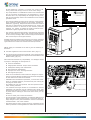
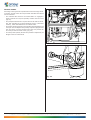
MANUALE USO E MANUTENZIONE
The iQ
USE AND MAINTENANCE MANUAL
DECLARATION OF CONFORMITY
Prosyd Srl
Via Roma,43 - 22077 Olgate Comasco (CO) Italy
states that the range of professional coffee machines model:
THE IQ ES/SOL
is complying with the safety measures foreseen by the directives:
1. Low Voltage Directive
2. Electromagnetic compatibility
EEC 73/23
EEC 93/68
EEC2006/95
- LV EEC 89/336
EEC 91/263
EEC 92/31
93/68
EEC 2004/108
-EMC3. MATERIALS AND ARTICLES IN CONTACT WITH FOOD
(1) REG. (EC) 1935/2004 on materials and articles intended to come into contact with food
(2) REG. (EC) 1895/2005 on the restriction of use of certain epoxy derivatives in materials
and articles intended to come into contact with food
(3) DIR. 2002/72 EC
relating to plastic materials and articles intended to come into
contact with foodstuffs
The tests have been made in accordance with the Harmonized European Standards
1) LOW VOLTAGE (Electrical safety LV):
EN 60335-1 : 2002 + A1+ A11
EN 60335-2-75: 2004+ A1
EN ISO 11201 + EN ISO 3744
(Safety of Household and Similar Electrical Appliances)
(Safety for Vending and dispensing Machines)
Measurement of acoustic noise
Sound Pressure Level: LpA < 70 dB(A)
2) ELECTROMAGNETIC COMPATIBILITY (EMC)
EN
EN
EN
EN
55014-1:2000+A1+A2
55014-2:1997+A1
61000-3-2: 2000+A2
61000-3-3:1995+A1+A2
EN 61000-4-4
EN 61000-4-5
EN 61000-4-6
EN 61000-4-11
EN 61000-4-2
EN 50366:2003 +A1 Measurement of Electromagnetic field
3) MATERIALS AND ARTICLES IN CONTACT WITH FOOD
D.M. 21-03-1973 and its amendements ⇒ D.M. 2006 May 4th nr. 227, and receiptment of
European Directives:82/711/EEC, 85/572/EEC, 93/8/EEC, 97/48/EC, 2002/72/EC, 2004/13/EC,
2004/19/EC, 2005/79/EC, Reg. EC n. 1935/04 e Reg.EC n. 1895/2005.
Olgate Comasco (CO), 2008 SEPTEMBER
CHIEF EXECUTIVE OFFICER
Aviel Dafna
BEFORE USING THE MACHINE, READ THIS MANUAL CAREFULLY FOR ITS CORRECT USE INACCORDANCE WITH THE CURRENT SAFETY STANDARDS.
SAFETY SYMBOLS
ATTENTION: Important safety indications
READ the instruction manual machine carefully before using the machine
For any service or maintenance switch off the machine
ATTENTION: machine switched on
ATTENTION: hot parts in contact!
PICTOGRAMS
IMPORTANT NOTICES
USER
The user is defined as the person authorized to collect drinks from the automatic beverage machine .
The user is not allowed to undertake any maintenance operations either ordinary or extraordinary.
In the event of a fault the user is obliged to notify the maintenance technician or the person responsible
for running the automatic beverage machine .
MAINTENANCE TECHNICIAN
The maintenance technician is defined as being the person responsible for filling up the containers with
soluble products, sugar, coffee, stirrers and cups.
The maintenance technician is also responsible for cleaning the beverage machine (see operations indicated
in chapter 7.0). In the event of a fault the maintenance technician must call the installation technician.
INSTALLATION TECHNICIAN
The installation technician is defined as the person responsible for the installation of the automatic beverage
machine , the starting up operations and the function settings.
Each regulation operation is the exclusive responsibility of the installation technician who also holds the
programming access password.
30
INDEX
1.0
1.0 PREMISE
1.1
1.1 Important notices
1.2 General Instructions
3.0 DESCRIPTION OF THE MACHINE’S
TECHNICAL CHARACTERISTICS
The user must not under any circumstances remove the
guards that require a tool for removal.
Description of the machine
Scheduled Use
Models
Basic instructions for the machine operation
Some maintenance operations (to be done solely by specialized
technicians and indicated in this manual with a special symbol)
require that specific safety protections of the machine must be
switched off .
4.0 TRANSPORTING THE AUTOMATIC
VENDING MACHINE
4.1
4.2
4.3
4.4
4.5
Important notices
This automatic beverage machine has been designed and constructed in full accordance with current safety regulations and is
therefore safe for those who follow the ordinary filling and cleaning
instructions as indicated in this manual.
2.0 TECHNICAL CHARACTERISTICS
3.1
3.2
3.3
3.4
PREMISE
In accordance with the current safety regulations, certain operations are the exclusive responsibility of the installation technician,
and the ordinary maintenance technician may have access to
specific operations on with specific authorization.
Moving and Transport
Stocking
Packing
Reception
Unpacking
The acquaintance and absolute respect, from a technical point of
view, of the safety instructions and of the danger notices contained
in this manual, are fundamental for the execution, in conditions
of minimum risk, for the installation, use and maintenance of
this machine.
5.0 SAFETY RULES
6.0 INSTALLATION
6.1
6.2
6.3
6.4
6.5
Positioning
Water supply connection
Power supply connection
Machine starting up
Installation
6.5.1 Filling of water circuit
6.5.2 Cleaning of parts in contact with food
substances
6.6 Product loading
6.6.1 Product container loading
6.6.2 Payment system installation
1.2
General Instructions
Knowledge of the information and instructions contained in the
present manual is essential for a correct use of the automatic
vending machine on the part of the user .
– Interventions by the user on the automatic vending machine
are allowed only if they are of his competence and if he has
been duly trained.
7.0 MAINTENANCE AND INACTIVITY
7.1 Cleaning and loading procedures
7.1.1 Procedure for beverage machine cleaning
7.1.2 Periodic cleaning by the maintenance
technician
7.1.3 Daily cleaning recommended
7.1.4 Weekly cleaning procedures
7.1.5 Product Loading instructions
7.2 Recommended maintenance
7.2.1 Ordinary and extraordinary maintenance
7.2.2 Coffee Group maintenance
7.3 Regulations
7.3.1 Dosage and grinding regulation
7.3.2 Instant electrovalve water flow regulation
7.4 When the unit is not working
The installation technician must be fully acquainted with all
the mechanisms necessary for the correct operation of the
machine.
– It is the buyer’s responsibility to ascertain that the users have
been trained and are informed and regulations indicated in the
technical documentation supplied.
Despite the full observance of the safety regulations by the
constructor, those who operate on the automatic dispensers
must be fully aware of the potential risks involved in operations
on the machine.
– This manual is an integral part of the equipment and as such
must always remain inside of the same, so as to allow further
consultations on the part of the various operators, until the
dismantlement and/or scrapping of the machine.
8.0 DISMANTLEMENT
– In case of loss or damage of the present manual it is possible
receive a new copy making application to the manufacturer,
with prior indication of the data registered on machines’ serial
number.
– The functional reliability and optimization of machine’s services are guaranteed only if original parts are used.
– Modifications to the machine not previously agreed on with
the construction company and undertaken by the installation
technician and/or manager, are considered to be under his
entire responsibility.
31
All the operations necessary to maintain the machine’s efficiency, before and during it’s use are at the users charge.
– Any manipulations or modifications made to the machine that
are not previously authorized by the manufacturer, relieve
the latter from any responsibility for damages deriving from,
and will automatically result in the cancellation of the machine
guarantee terms.
– This manual reflects the status at the moment of the emission
of the automatic vending machine on the market; possible modifications, upgrading, adaptments that are done the machine
and that are subsequently commercialized do not oblige the
constructor neither to intervene on the machine previously
supplied, nor, neither to update the relative technical documentation supplied together with the machine.
– It is however the constructor faculty, when deemed opportune
and for valid motives, to adjourn the manuals already present
on the market, sending to their customers adjournment sheets
that must be kept in the original manual.
Possible technical problems that could occur are easily resolvable
consulting this manual; For further information, contact the beverage machine from whom the machine has been purchased.
IWhen calling it is advisable to be able to give the following information:
The data registered on the serial number label (Fig.1.1)
FIG.1.1
The version of the programme contained in the microprocessor
(adhesive label applied to the component the assembled on the
Master board ) (Fig.1.2).
The constructor declines any responsibility for damages caused
to people or belongings in consequence to:
Incorrect installation
Inappropriate electrical and/or water connection.
Inadequate cleaning and maintenance
Not authorized modifications
Improper use of the beverage machine
Not original spare parts
– Under no circumstances is the constructor obliged to compensate for eventual damage resulting from the forced suspension
of drink deliveries as the result of faults.
– Installation and maintenance operations , must be done exclusively by qualified technical personnel with prior training for
carrying out these duties.
– For refilling use only food products that are specific for automatic vending machines.
– The automatic beverage machine is not suitable for external
installation. The machine must be installed in dry places, with
temperatures that never go below 1°C it must not be installed
in places where cleaning is done with water hoses (ex. big
kitchens.).
FIG.1.2
Do not use water jets to clean the machine.
– If at the moment of the installation, if conditions differing from
those indicated in the present manual, or should the same undergo changes in time, the manufacturer must be immediately
contacted before use of the machine.
– Also check that any other eventual norms or regulations as laid
down by national or local legislation are taken into account and
32
2.0 TECHNICAL CHARACTERISTICS
Height (A)
mm 610
Width (B)
mm 387
Depth (C)
mm 480
Weight
kg 32,2
Power Supply
V 230 - V 120
Power frequency
Hz. 50 - Hz. 60
Installed power (1)
From 1,63 to 2,1 kW
BOILER RESISTANCES
of armoured type:
1500 W for espresso boiler version
2000 W for the instant powder boiler version
PRODUCT CONTAINER CAPACITY
AVERAGE CONSUMPTIONS:
Water supply connection
3/4” gas
Electrical supply connec.
Schuko plug
WATER SUPPLY
Coffee bean container
kg 0,8
Instant coffee
kg 0,35
Powder milk
kg 0,5
Powder milk (Double unit)
kg 1,0
Chocolate
kg 1,0
Chocolate (Double unit)
kg 2,0
Lemon tea
kg 1,4
Natural tea
kg 0,85
Broth
kg 1,2
Sugar
kg 1,3
from main supply with pressure between 0.5 and 6.5 bar
(1)
Check the rated output indicated on the data plate applied by
the beverage machine .
Fig. 2.1
33
3.0
GENERAL TECHNICAL DESCRIPTIONS
3.1
Machine description
Espresso version (Fig. 3.1)
1 Keyboard cards
2 Container units for soluble drinks and sugar
3 Master board
4 Espresso boiler
5 Coffee group and grinder
6 Water supply mains inlet
7 Power supply mains infeed
Espresso version
Fig. 3.1
34
3.2
Machine description
Instant version (Fig. 3.2)
1 Keyboard cards
2 Container units for soluble drinks and sugar
3 Master board
4 Instanr bolier
5 Water supply mains inlet
6 Power supply mains infeed
Instant version
Fig. 3.2
35
3.3
Foreseen use
The beverage machine is exclusively for the dispensing of drinks,
prepared mixing food substances with water (by infusion as far
as concerns coffee).
For this purpose use products declared as suitable by the manufacturer for automatic distribution in open containers.
The plastic cups and the stirrers for sugar mixing will be placed at
the disposal of the user as they are not automatically dispensed
by the “The iQ” beverage machine.
The drinks must be consumed immediately and in no case are to
be kept for subsequent consumption.
3.4 Basic operation concepts
During the normal functioning the beverage machine remains in
standby status.
Introducing the necessary amount, according to the set price,
and after pressing the key relative to the desired drink, the
drink dispensing cycle is activated and can be divided different
processes:
Fig. 3.3
CUP AND SPOON COLLECTION
The “The iQ” automatic beverage machine does not feature an
automatic cup and spoon beverage machine . The user must
therefore procure the same in an independent manner from the
special beverage machines placed at disposal in the vicinity of the
beverage machine , and must undertake to position them correctly
in the delivery compartment (fig. 3.3).
The presence and/or dimension of the cup can be automatically
detected by the beverage machine (optional feature) by way of 3
photo-sensors lodged into the cup compartment.
In general, the acknowledgement of the size of the cup is based
on the following principle outlines:
Bevanda standard
o regular
#
Fig. 3.4
#
Bevanda lunga
o long
#
SUGAR DISPENSER
Where provided for and where requested, a set, maximum dose
quantity of sugar is dispensed.
For both versions, the sugar is pre-mixed in with the beverage.
#
#
The delivery procedure is as follows:
Bevanda molto lunga
o extra-long
The geared motor operates the sugar container volute, pouring the
required amount inside the powder conveyor (fig.3.4).
#
36
INSTANT DRINKS
According to the type drink requested and to the beverage machine model, several of the various processes described here below
can be activated.
– The solenoid valve fixed to the instant boiler is engaged in
order to deliver the required quantity of water into the mixer
(fig.3.5).
– The pump that delivers the required amount of water is activated; and controlled by a special electronic device (volumetric
counter), which withdraws from the instant boiler.
– The instant product geared motor activates the helicoidal screw
conveyor so as to dispense the quantity of product programmed
into the mixer (in some versions more than one product can
be conveyed into the same mixer) (Fig.3.6)
– once the preset quantity of water and powder is dispensed, the
whipper motor is switched off.
Fig. 3.5
Fig. 3.6
37
ESPRESSO COFFEE
This process functions only the models equipped with the coffee
espresso group, after the cup and sugar dispensing processes
have been effected.
– the grinder is activated until it reaches the dose of ground coffee
set by the doser (Fig.3.7)
– the doser electromagnet is activated , causing the opening of the
door and consequent fall of the coffee into the brew chamber
– the rotation group geared motor brings it into the dispensing
position and simultaneously compresses the ground coffee
(Fig.3.8).
– the pump that dispenses the quantity of programmed water and
that is controlled by a specific electronic device, (volume meter),
withdrawing the water from the coffee boiler (Fig.3.9).
– the coffee group geared motor is activated again so as to bring
again into standby position; during this movement the used
coffee grounds are expelled (Fig.3.10).
Fig. 3.7
The operational sequence (coffee grinding and release) may
occur in an inverse order according to the type of programming
involved.
Fig. 3.8
Fig. 3.10
Fig. 3.9
38
4.0 MOVING AN AUTOMATIC VENDING
MACHINE
4.1
Moving and transport (Fig.4.1)
The beverage machine must be shifted by 2 people (Fig.4.1).
Avoid :
– lifting the beverage machine with ropes or presses
– dragging the beverage machine
– upset or lay down the beverage machine during transport
– give jolts to the beverage machine
Prevent the beverage machine from:
– being knocked
– Stacking other objects on it
– Being exposed to the elements
– Positioned in damp places
kg 32,2
The construction company is not liable for any damage which
may be caused for the partial or complete non-observance of the
warning notices indicated above.
4.2
stocking
For eventual stocking, avoid laying several machines over each
other, maintain it in vertical position, in dry places with temperatures not inferior to 1°C.
4.3
Packing
Fig. 4.1
The beverage machine is supplied in a cardboard box protected
by polystyrene packaging (Fig.4.2).
The automatic beverage machine will be delivered packed, assuring
both a mechanical protection and protection against damages
from the external environment.
On the package labels are applied indicating:
maneouver with care
don’t turn upside-down
protect from the rain
don’t superimpose
protect from sources of heat
not resistant against bumps
type of beverage machine and serial number.
4.4
Reception
Upon reception of the automatic beverage machine you need to
check that the same has not suffered damages during the transport.
If damages of any nature are noticed place a claim with the
forwarder immediately.
At the end of the transport the packing must result
without damages which means it must not :
– present dents, signs of bumps, deformations or damages of the
external packaging
– present wet zones or signs that could lead to suppose that the
packing has been exposed to rain, cold or heat.
– present signs of tampering
4.5
Unpacking
Remove the beverage machine from its packaging, lifting the
polysterene panels and removing it from the box (Fig.4.2).
Fig. 4.2
39
– remove the key from the drink dispensing chamber (Fig.4.3)
In some versions the key is not provided because the beverage
machine is equipped with a magnetic closing option.
– open the door of the beverage machine and remove the adhesive
tape from the components listed here below:
coin box
coin mechanism cover / keyboard cards
product containers
The packing material must not be left accessible to
others, as it is a potential environmental pollution
sources. For the disposal contact qualified companies
authorized.
Fig. 4.3
40
5.0
6.0
SAFETY NORMS
6.1
ATTENTION!
WARNING! Do not position the device near inflammable
objects, keep a minimum safety distance of 30 cm.
Always disconnect the POWER CABLE before
maintenance or cleaning interventions.
–
–
–
–
Positioning
– As already specified in paragraph 5.0, “Safety norms”, the
beverage machine is not suitable for external installation. The
machine must be connect in dry places, with temperatures that
never go below 1°C it must not be installed in places where
cleaning is done with water hoses(ex. big kitchens.) . It must
be installed in places without danger of explosions or fires.
– If positioned near to a wall, there must be a minimum distance
from the wall of at least 5 cm. (Fig.6.1) so as to allow a regular
ventilation. In no case cover the beverage machine with cloths
or similar.
– before using the automatic beverage machine , read this manual
carefully.
– The installation and maintenance operations must be performed
exclusively by qualified technical personnel.
– The user must not in any circumstance be able accede to those
parts of the automatic beverage machine that are protected and
require a tool in order to be accessible.
– The knowledge and the absolute respect, from a technical point
of view of the safety instructions and of the danger notices contained in this manual, constitute the basis for the operation ,
in conditions of minimum risk, of the installation, starting and
maintenance of the machine.
–
INSTALLATION
Bianchi Vending S.p.A. declines all responsibility for inconveniences due to the non observance of the above mentioned
installation norms.
If the installation is made in safety evacuation corridors make
sure that with the beverage machine door open there is anyhow
sufficient space to pass by (Fig.6.1).
So as to avoid that the floor gets dirty, due to accidental spilling
of the products, use, if necessary, under the beverage machine,
a protection sufficiently wide to cover the beverage machine s’
operating space.
ABSOLUTELY DO NOT INTERVENE ON THE MACHINE
AND DO NOT REMOVE ANY PROTECTION BEFORE THE
COOLING OF THE HOT PARTS!
The functional reliability and optimization of machine’s services are guaranteed only if original parts are used.
The beverage machine is not suitable for external installation. The machine must be connect in dry places, with
temperatures that never go below 1°C it must not be installed in places where cleaning is done with water hoses
(ex. big kitchens). Do not use water jets to clean the
machine.
In order to guarantee normal operation, the machine must be
installed in areas that the environmental temperature is between
a minimum of -1°C and a maximum of +32°C end humidity of
not over 70%.
In order to guarantee a regular operation, always maintain the
automatic beverage machine in perfect cleaning conditions
Bianchi Vending S.p.A. declines all responsibility for damages
product to people or belongings in consequence to:
6.2
Connection to the main water supply
Before proceeding with the connection of the beverage machine to
the water main supply verify the following water characteristics:
– that it is drinkable (eventually through an laboratory’s analysis
certification)
– it has a pressure comprised between 0.5 and 6.5 bar ( if this
should not be the case, use a pump or a water pressure, reducer
according to the case).
Incorrect installation
Inappropriate electrical and/or water connection.
Inadequate cleaning and maintenance
Not authorized modifications
Improper use of the beverage machine
Not original spare parts
– Futhermore verify observance of any other eventual local and
national standards.
Fig. 6.1
41
– install, if not present, a tap in an accessible position to isolate
the machine from the water mains should it be found to be
necessary (Fig.6.2).
– before making water connections, make some water flow out
of the tap so as to eliminate possible traces of impurities and
dirt (Fig.6.3)
– connect the cock to the beverage machine, using a pipe in nylon
material suitable for food products and suitable for the mains
pressure. In the event of the use of a flexible pipe it is necessary
to fit the reinforcement bush supplied inside (Fig. 6.4).
– the foreseen connection is a 3/ 8 gas (Fig.6.5).
Fig. 6.2
6.3
Main Power supply connection
Fig. 6.3
The beverage machine is suitable for operation at single-phase
voltage of 230 volt and is protected by 2 12.5 A fuses and by a
10A fuse on the MASTER card.
We suggest to check that:
– the tension of net of 230 V doesn’t have a difference of more
than ± 10%
– The power supply output is able to bear the power load of the
machine.
– use a system of diversified protection
– position the machine in such a way as to ensure that the plug
remains accessible
The machine must be connected to earth in observance with the
current safety norms.
For this reason, verify the plant’s earth wire connection to ascertain
that it is efficient and it answers national and European safety
electric standards. If necessary require the intervention qualified
personnel for the verification of the plant.
Fig. 6.4
– The beverage machine is equipped with a power supply cable
of H05VV-F 3x1 mm², with SCHUKO plug (Fig.6.6).
– The sockets that are not compatible with that of the machine
must be replaced. (Fig.6.7).
– The use of extension, adapters and/ or multiple plugs is forbidden.
Bianchi Vending S.p.A. declines all responsibility for
damages deriving for the complete or partial failure to
observe these warnings.
Should the power cable be found to be damaged, immediately
disconnect from the power socket.
The power supply cables are to be replaced by skilled personnel.
Fig. 6.5
OK
Fig. 6.6
Fig. 6.7
42
6.4
Starting up of the unit
The beverage machine is provided with a connection cable for
connection to the mains water supply (fig.6.8) and a switch which cuts off the power from all users each time that it is operated
(fig.6.9).
Should it be necessary to operate inside the beverage machine
for any ordinary or special maintenance operates, it is necessary
to isolate the user appliances by activating the switch (fig.6.10),
bearing in mind that with the electrical connection engaged, the
power terminals are live.
Each time the beverage machine is switched on a diagnosis cycle
is performed in order to verify the position of the mobile parts and
the presence of water and of some products.
Fig. 6.8
Fig. 6.9
Fig. 6.10
43
6.5 Installation
6.5.1
Boiler fill-ups
The standard boiler fill-up function is provided with a 25 second
timeout setting, within which the level detection sensors must
detect the presence of water.
If this is not the case, the “LACK WATER - CALL SERVICE” message
comes up on display and the beverage machine will therefore not
work for beverage supplies.
STOP
It is however possible to start an extended, boiler fill up procedure,
in all cases in which total boiler fill-up is required, for instance at
first machine installation, or after the boiler has been emptied out
for moving and transporting of the beverage machine.
In order to start said first-time boiler fill-up procedure, it is necessary to press the “STOP DISPENSING” key located on the beverage
machine’s keypad within the first 2 seconds after having started
the machine up and to hold it pressed in for 3 seconds.
In this case, the boiler fill-up procedure must complete itself within
4 minutes. Should the boiler not fill-up within a 4 minute timeout, the beverage machine will keep trying for 3 hours with water
entry electro valve switch-on and switch-off cycles respectively of
4 and 6 minutes each, in order to avoid overheating of the electro
valve winding.
Fig. 6.11
– at the end of the water filling (Fig.6.12), effect a cleaning cycle
of the mixer group so as to fill all the circuits and remove eventual residues from the boiler.
In the beverage machine’s installation phase, ascertain,
before switching it on, that the same is connected to the
water supply and that the water faucet is open.
Fig. 6.12
44
6.5.2 Cleaning of the parts in contact with food substances
With beverage machine switched on effect a cleaning of the mixers
pressing the buttons according to what is described in the service
functions so as to eliminate any dirt from the coffee boiler and
the instant boiler.
– wash your hands carefully
– prepare an anti-bacterial cleaning solution with a chlorine base
(products that can be purchased in pharmacies) following the
concentrations given on the product instruction labels.
Before removing the container lower the flap in order to
prevent the accidental escape of the soluble product inside
the same (fig. 6.13).
– Lift the beverage machine’s top shutter door (fig. 6.14).
Fig. 6.13
– remove all the product containers from the beverage machine
(fig. 6.15).
– remove the lids from the product containers covers and product
chutes (Fig.6.16). Dip all in the solution previously prepared
Fig. 6.14
Fig.6.16
Fig. 6.15
45
– remove all the powder chutes, water funnels, mixing bowls
and whippers and silicone tubes and dip these parts also in
the prepared solution (Fig.6.17)
– with a cloth soaked with the solution clean the whipper assembly
base (Fig.6.18)
– the parts must soak in the solution for the time indicated on
the solutions’ instruction label.
– Recover all the parts, rinse them abundantly, dry them perfectly
and proceed with the re-assembly in the beverage machine.
After re-positioning the container undertake to raise the
flap in order to reset the correct function (fig. 6.19).
Fig. 6.17
For further safety after the assembly of the parts, effect
some automatic cleaning cycles so as to eliminate any
eventual residues.
Fig. 6.18
Fig. 6.19
46
6.6
Product container loading
(with machine off)
6.6.1
Loading containers
Filling is possible keeping the containers inserted, and by raising
the upper flap of the beverage machine (Fig. 6.20) or by extracting each container.
For granulated coffee in particular it is necessary to close the
closure plat before extracting the container.(Fig.6.21).
– remove the covers of each container and load the product according to the product indicated on the label (Fig.6.22-Fig.6.23).
– pay attention that they there are no clots, avoid pressing the
product and using an excessive quantity, so as to avoid its
aging in relation to the consumption forseen in the time period
between two loadings.
Fig. 6.20
Check the container product capacity in the section TECHNICAL
CHARACTERISTICS.
6.6.2
Payment system installation
The beverage machine does not have a payment system; any
possible damages to the beverage machine itself and/or objects
and/or people deriving from its incorrect installation are responsibility of who installs the payment system.
The switches are to be directly connected to the keyboard card,
the executive serial systems require the RS232 payment system
kit supplied separately.
Then go into programming for the correct settings.
Consult manual ”Software instructions” so as to verify setting of
the parameters, that must be coherent with the system used.
Fig. 6.21
Fig. 6.23
Fig. 6.22
47
7.0 MAINTENANCE AND INACTIVITY
7.1
7.1.3 Daily cleaning recommended
The objective is that to avoid the creation of bacteria in the food
zone areas.
Cleaning and Loading
So as to guarantee the correct functioning of the beverage
machine during time it is necessary to effect some operations periodically, some of which are indispensable for the
observance of the health standard norms. These operations
must be done with the beverage machine open and switched
off. The cleaning operations must be effected before the loading of
the products. In order to guarantee normal operation, the machine
must be installed in areas that the environmental temperature is
between a minimum of -1°C and a maximum of +32°C end humidity
of not over 70%. Must not be installed in places where cleaning is
done with water hoses(ex. big kitchens.).
Do not use water jets to clean the machine.
For all cleaning operations follow the instructions indicated
in paragraph 7.1.1.
Operate as follows:
- clean all the visible parts in the dispensing area. (Fig. 7.1 e
Fig. 7.2)
remove and clean carefully:
– funnels and powder chutes (Fig. 7.3-pos.1)
– water funnel (2), mixing bowls (3) whipper assembly (4)
7.1.1
Procedure for beverage machine cleaning
Recommended equipment:
For those responsible for filling up and maintenance of the machine
the recommended equipment is as follows:
- Tool carrier case
- Clean uniform
- Disposable gloves
- Clamp for closing the
- Roll of kitchen paper
- Wood or plastic stick
- Bottle of detergent
- Bottle of disinfectant
- “Beverage machine out of action” sign
- Small table for resting items (optional)
Never use:
- Sponges, scourers, cloths
- Brushes
- Screwdrivers or metallic objects.
Fig.7.1
To ensure hygiene:
- Use disinfectants
For cleaning:
- Use detergents and/or detersive products
The purpose of the disinfectants is to destroy any surface bacteria which may be present. The detergents act to eliminate the
dirt. Products exist on the market which are both detergents/
disinfectants and are usually sold at the chemist’s.
On application of the HACCP certain hygienic regulations are
laid down for company self-checking procedures concerning :
- Cleaning of the premises
- Product transportation
- Machinery maintenance
- Waste disposal
- Drinking water procurement
- Personnel hygiene
- Food product characteristics
- Personnel training
- (Directive 93/43 CEE)
Fig.7.2
The cleaning operations may be undertaken:
1 at the site of installation of the automatic beverage machine
2 at the premises of the company that provides the service
Example of a recommended cleaning procedure of a hot
drink automatic beverage machine :
The person responsible for machine hygiene, before opening the
beverage machine must check the cleanliness of the surrounding environment and put up a sign to tell any potential consumers that:
- the machine is “out of use as maintenance is in progress”
- it is important that the person responsible for cleaning never
has to interrupt his work in order to operate the machine.
7.1.2
Periodic cleaning by the maintenance technician
First step: disposal of the waste inside the waste bins (used cups,
stirrers, paper, tissues etc).Once the waste has been disposed of
it is possible to clean the surrounding area.
- elimination of the coarse dirt
- disinfecting of the flooring and walls of the area surrounding
the machine up to a radius of 1 metre around the beverage
machine
- once this is complete proceed with opening the beverage machine .
Fig.7.3
48
– silicone water dispensing tubes.
– dispensing chamber (Fig. 7.4)
– coffee funnel and chute (Fig. 7.5)
Before effecting the re-assembly operations clean all the elements
carefully.
– remove all coffee powder residue; the unit can be removed
from its housing to make the task easier (Fig. 7.6)
Fig.7.4
Fig.7.5
Fig.7.6
7.1.4
– Empty out the discharge liquids tray - clean and/or replace
(Fig. 7.7).
– substitute the coffee spent grounds container (coffee in beans
versions) (Fig. 7.8).
Last step: coin collection.
Fig.7.7
Weekly cleaning
Remove all the containers and clean with a wet cloth all the container
support parts, as well as the bottom of the beverage machine and
the outside of the beverage machine, in particular the dispensing
area. (Fig. 7.9).
Fig.7.8
Fig. 7.9
49
7.1.5 Product loading
When necessary provide for the loading of the products and/or
consumption materials of the automatic vending machine.
For these operations please refer to the operations described under
chapter 6.6 (first installation).
7.2 Recommended
maintenance
TIME / No.of COUN
TYPE OF INTERVENTION
EVERY DAY
EVERY WEEK
Remove and wash all visible parts in the delivery area with sanitizing liquid.
Empty the liquid ground collecting buckets and clean them with
sanitizing liquid.
Empty the coffee ground collecting tank and wash it with sanitizing liquid
Remove all containers and clean with a wet cloth all container
supporting parts, as well as the bottom and the outside of the
beverage machine, in particular the delivery area; then proceed
to sanitization.
* Sanitization kits including plastic parts for the passage of pulverized or liquid product (cups, pipes, delivery flange, nozzles,…). For any further information, please contact directly our
offices.
* Bianchi Vending Group has prepared specific kits expressly designed for every beverage machine mode
7.2.1 Ordinary and Extraordinary Maintenance
The operations described in this section are purely indicative
as they are tied to variable factors such as the water hardness,
humidity, products used and workload, etc.
For all operations that require the disassembly of
the beverage machine s’ components, make sure
that the latter is switched off.
Entrust the operations mentioned here below to qualified personnel.
If the operations require that the beverage machine be switched
on, entrust them to specially trained personnel.
For more complicated interventions, such as removing the lime
build-up in the boilers a good knowledge of the equipment is
necessary.
Monthly effect the debacterisation of all the parts in contact with
food substances using chlorine based solutions following the
operations already described under chapter 6.5.
50
20000 COUN OR
MAX EVERY MONTH
7.2.3 Coffee group maintenance
Monthly extraction of the unit and thorough rinsing in hot water
is recommended.
The necessary requirement for this operation is that the coffee
unit is in idle position.
Then detach the pipe indicated in Fig. 7.10, unscrew knob A, rotate
lever B (Fig. 7.11) and then remove the entire coffee unit.
Every 5000 vends and anyhow monthly, it is advisable to lubricate all the mobile parts of the group, using silicone grease for
alimentary use Fig. 7.12):
– lower filter piston (1)
– connecting bar (2)
– piston guide (3)
Every 10000 vends we advise to substitute the gaskets and the
filters.
– gaskets
– Loosen the screw (Fig. 7.13), wash the filter and replace if
necessary.
Fig. 7.10
– re-assemble everything in the inverse order.
Fig. 7.11
Fig. 7.12
Fig. 7.13
Fig. 7.14
COFFEE MACHINE TIMING CHECK PROCEDURE
Ensure that during the delivery stage that the rotating index is
not more than 1.5 mm in advance of the delivery reference point
(the rotating index must be at a delivery position of between 0
and 1.5 mm from the delivery point).
Ensure that during the idle state, the rotating index is aligned with
the stage index (see fig.7.14)
51
7.3 Regulations
7.3.1 Dosage and grinding regulations
The beverage machine is supplied regulated with standard values
and i.e.:
– TEMPERATURE of the coffee in the cup of about 78°C for 38 cc
of dispensed product
– TEMPERATURE of the instant products in the of about 73°C
– grams of coffee powder, about 7,0 grams
– grams of instant powder products according to what is indicated
on the specific tables.
In order to obtain the best results with the product used we advise
to check:
- Ground coffee gram weighting: vary the quantity using the knob
positioned on the measuring device (Fig.7.15).
Each notch of the regulation knob corresponds to a value of
0.05 grams.
By turning in a clockwise sense the amount decreases.
By turning in an anti-clockwise sense the amount increases.
The variation in the product can be controlled by means of the
reference notches on the body of the measuring unit (see figure
7.15)
Coffee pellets must be have a compact consistency and be
slightly damp.
– Regulation of the degree of grinding. Turn the screw (fig.7.16)
to obtain the desired results.
Turn clockwise for fine grinding, turn anti-clockwise for coarser
grinding.
After regulation, three product regulations must be carried out
in order to assess the efficiency of the regulation, the finer the
granules the greater the time required for product delivery.
7.3.2 Regulation of the instant solenoid water delivery valves
(version soluble only)
In the case of soluble products you can regulate the quantity of
water and the powder dosage electronically by varying the standard
parameter, according to the procedure indicated in the manual
”Software instructions”.
Fig. 7.16
Due to problems caused by the formation of lime scale the instant
solenoid valves can have a reduced water delivery.
52
7.4 Inactivity
If the automatic vending machine remains inactive for a long time
it is necessary to perform some prevention operations:
– disconnect the machine electrically and hydraulically.
– empty completely the instant boiler and the floater reservoir
removing the plug located on the hose along the drain chute.
– Put the plug back in once the draining has been done.
– unload all the product from the containers (Fig. 7.17)
– perform a thorough cleaning of all the parts in contact with food
substances according to what has already been described.
– empty the liquid waste bin carefully
– eliminate the spent grounds bag
– clean with a cloth all the internal and external surfaces of the
machine.
– protect the outisde of the machine with a plastic film wrapping
or bag.
– stock in a dry and protected place where the temperature is
not less than 1° C.
Fig. 7.17
8.0 DISMANTLEMENT
Proceed with the emptying of the products and of the water as
described in the previous paragraph.
For the dismantlement we advise to disassemble the machine
dividing the parts according to their composition (plastic, metal
etc.).
Subsequently entrust to specialised companies the parts divided
in this manner.
Attention! Check that the machine disposal is perfomed with
respect of environmental rules and according to the regulations
in force
53
Prosyd Srl
Via Roma, 43
22077 Olgate Comasco