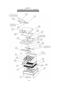
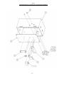
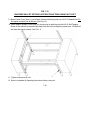
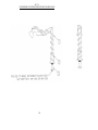
1
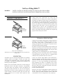
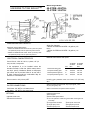
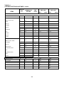
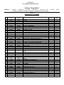
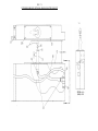
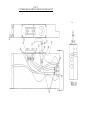
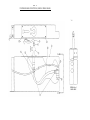
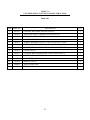
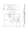
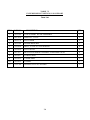
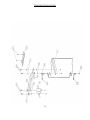
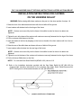
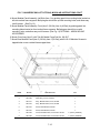
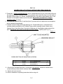
UniVerse Skillet™
GAS-FIRED FRYING AND BRAISING PAN
TECHNICAL MANUAL
COVERING
• Installation
• Operation
• Service and Parts
MODELS:
30-STGL, 30-STGL-LX, 40-STGL, 40-STGL-LX,
30-STGM, 30-STGM-LX, 40-STGM, 40-STGM-LX
WARNING
Improper Installation, adjustment, alteration, service, or maintenance
can cause property damage, injury, or death. Read the installation,
operating, and maintenance instructions thoroughly before installing or
servicing this equipment.
FOR YOUR SAFETY
Do not store or use gasoline or other flammable vapors and liquids
in the vicinity of this or any other appliance.
In a prominent location, post
instructions to be followed in the
event the user smells gas. This
information shall be Obtained by
consulting the local gas supplier.
MARKET FORCE
[INDUSTRIES
INC
An Employee-Owned Company35 Garvey Street • Everett, MA 02149-4422 USA Tel. (617) 387-4100
Fax (617) 387-4456 Fax Outside MA- 1-800-227-2659 E-Mail CUSTSERV@MFn COM Form No. S-2469
Date of original page is:
Original March 10, 1998
Total number of pages in this publications is 44, consisting of the following:
PAGE NO
I
Cover Page
ii
List of Effective Pages
iii
Table of Contents
iv
List of Illustrations
v
Summary of Safety Notices
vi
[Page left intentionally blank]
SECTION
1 GENERAL INFORMATION
1-1
1-2
SECTION
0
0
2 INSTALLATION INSTRUCTIONS
2-1
2-2
2-3
2-4
2-5
2-6
2-7
SECTION
4-1
4-2
4-3
4-4
PAGE NO
SECTION 5 ILLUSTRATED PARTS LISTS
3 OPERATING INSTRUCTIONS
0
0
0
4 TEST KITCHEN BULLETI N
0
0
0
0
CHANGE NO*
5-1
5-2
5-3
5-4
5-5
5-6
5-7
5-8
5-9
SECTION
0
0
0
0
0
0
0
3-1
3-2
3-3
SECTION
CHANGE NO
0
0
0
0
0
0
0
0
0
0
0
0
0
0
0
6 TROUBLESHOOTING AND MAINTENANCE
6-1
6-2
6-3
SECTION
7-1
7-2
7-3
7-4
7-5
7-6
7-7
7-8
7-9
7-10
7-11
7-12
7-13
7-14
7-15
7-16
7-17
7-18
7-19
7-20
7-21
7-22
7-23
7-24
0
0
0
7 OPTIONS PARTS LISTS
0
0
0
0
0
0
0
0
0
0
0
0
0
0
0
0
0
0
0
0
0
0
0
0
TABLE OF CONTENTS
List of Effective Pages................................................................................................................................................................ ii
List of Illustrations..................................................................................................................................................................... iv
Summary of Safety Notices ...........................................................................……………………………………..................... v
SECTION 1 GENERAL INFORMATION
SECTION 2 INSTALLATION INSTRUCTIONS
Installation of UniVerse Tilting Skillet (with Pilot)......................................................................................... 2-1
General Installation ....................................................................................................................…..............2-1
Installation with Casters ..............................................................................................................................2-1
Lighting Instructions for Tilting Skillet Pilot and Burners.......................................................................... 2-2
Shutdown Instructions.....................................................................................................................….…... 2-2
Installation of UniVerse Tilting Skillet (with Pilotless Ignition) ........................................................…...........2-3
General Installation ..........................................................................................................................….........2-3
Installation with Casters ...............................................................................................................................2-3
Lighting Instructions for Tilting Skillet Glow Coil..................................................................................... 2-4
Shutdown Instructions................................................................................................................................. 2-4
Prolonged Shutdown ....................................................................................................................................2-4
SECTION 3 OPERATING INSTRUCTIO NS
Introduction......................................................................................................................….............................. 3-1
Operation of UniVerse Tilting Skillet (with Pilot)............................................................…............................. 3-1
Operation of UniVerse Tilting Skillet (with Pilotless Ignition)..........................................…........................... 3-3
SECTION 4 TEST KITCHEN BULLETIN
Cooking Facts on Parade .............................................................................................….................................. 4-1
Table 4.1 Cooking Portions and Times........................................................................…................................ 4-2
SECTION 5 ILLUSTRATED PARTS LISTS
Table 5.1
Table 5.2
Table 5.3
Table 5.4
UniVerse Skillet, Top Assembly Parts List .................................................…................................5-1
UniVerse Skillet, Pan Assembly Parts List......................................................…............................ 5-4
UniVerse Skillet, Standing Pilot Nema Box Assembly Parts List......................….......................... 5-6
UniVerse Skillet, Carborundum Nema Box Assembly Parts List......................................….......... 5-8
SECTION 6 TROUBLESHOOTING AND MAINTENANCE
Table 6.1 Troubleshooting Guide ...........................................................................................................…..... 6-1
Calibration of Temperature Control............................................................................................................…... 6-1
Replacement of Temperature Control...........................................................................................................…. 6-2
Adjustment of Interlock Switch ....................................................................................................................…..6-2
Figure 6.1 Control Circuit Board .................................................................................................................… 6-2
Cleaning and Preventive Maintenance..................................................................................…......................... 6-3
SECTION 7 OPTIONS PARTS LISTS
Table 7.1
Table 7.2
Table 7.3
Table 7.4
Table 7.5
Table 7.6
Table 7.7
Table 7.8
UniVerse Skillet Options, Single Pantry Faucet Parts List...................................................…...... 7-1
UniVerse Skillet Options, Double Pantry Faucet Parts List ................................................…....... 7-3
UniVerse Skillet Options, Single Spray Hose Parts List...................................................….......... 7-5
UniVerse Skillet Options, Double Spray Hose Parts List.................................................….....….. 7-7
UniVerse Skillet Options, Pan Support Parts List..................................................................…..... 7-9
UniVerse Skillet Options, Casters with Gas Strain Relief ......................................................…... 7-11
UniVerse Skillet Options, Casters..........................................................................................…... 7-11
UniVerse Skillet Options, Gas Strain Relief........................................…..................................... 7-11
TABLE OF CONTENTS
(con't)
Table 7.9 UniVerse Skillet Options, Modular Panels ..............................................…...............……..……....7-13
Table 7.10 UniVerse Skillet Options, Trim Joining Kit..........……………………………………………..….7-17
Table 7.11 UniVerse Skillet Options, Spring Support For Spray Hose …………………………………........ 7-21
Table 7.12 UniVerse Skillet Options, Tangent Draw-Off ...........................................................……...............7-23
LIST OF ILLUSTRATIONS
SECTION 2 INSTALLATION INSTRUCTIONS
Figure 2.1 Wiring Diagram, Manual Tilt Standing Pilot Units ......................…………………………………… 2-5
Figure 2.2 Wiring Diagram, Power Lift Standing Pilot Units……………………………………………............. 2-6
Figure 2.3 Wiring Diagram, Carborundum Units ………………………………………..………………………. 2-7
SECTION 5 ILLUSTRATED PARTS LISTS
Figure 5.1 UniVerse Skillet, Top Assembly -...........................………………………………………………….. 5-3
Figure 5.2 UniVerse Skillet, Pan Assembly ………………………………………………................................... 5-5
Figure 5.3 UniVerse Skillet, Standing Pilot Nema Box Assembly …………………………................................. 5-7
Figure 5.4 UniVerse Skillet, Carborundum Nema Box Assembly ……………………………………………….. 5-9
SECTION 6 TROUBLESHOOTING AND MAINTENANCE
Figure 6.1 Temperature Control Circuit Board……………………………………………………………….……6-2
SECTION 7 OPTIONS PARTS LISTS
Figure 7.1 UniVerse Skillet Options, Single Pantry Faucet………………………………………………………..7-2
Figure 7.2 UniVerse Skillet Options, Double Pantry Faucet.....………………………......................................... 7-4
Figure 7.3 UniVerse Skillet Options, Single Spray Hose ………………………………...................................... 7-6
Figure 7.4 UniVerse Skillet Options, Double Spray Hose....……………………………………………............... 7-8
Figure 7.5 UniVerse Skillet Options, Pan Support .……………………………………………........................... 7-10
Figure 7.6 UniVerse Skillet Options Casters with Gas Strain Relief....…………………………………………. ..7-12
Figure 7.7 UniVerse Skillet Options, Casters ................................……………………………………………… 7-12
Figure 7.8 UniVerse Skillet Options, Gas Strain Relief...................…………………………………………....... 7-12
Figure 7.9 UniVerse Skillet Options, Modular Panels...………………………………………………………….. 7-14
Figure 7.10 UniVerse Skillet Options, Trim Joining Kit …………………………………………………………..7-18
Figure 7.11 UniVerse Skillet Options, Spring Support For Spray Hose........................................……….............. 7-22
Figure 7.12 UniVerse Skillet Options, Tangent Draw-Off...............…………………………………..………….. 7-24
SUMMARY OF
SAFETY NOTICES
UniVerse Tilting Skillet TM
MODELS:
30-STGL, 30-STGL-LX, 40-STGL, 40-STGL-LX, Open-Leg Gas UniVerse Skillet
30-STGM, 30-STGM-LX, 40-STGM, 40-STGM-LX, Modular Gas UniVerse Skillet
The following general safety notices supplement the specific
warnings and cautions contained in this technical manual. They are
recommended precautions that must be understood and adhered to
during the installation, operation, and maintenance of these
electrically operated appliances.
CAUTION
Do not install in such a manner that the service person cannot
remove the control box cover.
WARNING
Supply wires must be suitable for temperature of at least 90°C.
Additionally, all wiring must conform to the requirements of local
and national electric codes. Conduit and fittings should be
watertight type.
Do not get water on wiring in controls. Be sure to wash inside of
skillet pan, inside of cover including under drip-lip, and pouring
spout area.
Unit is equipped with an interlock switch that shuts off gas to the
burners when skillet pan is more than 10° above normal horizontal
cooking position.
UniVerse Tilting Skillet™
MODELS:
30-STGL, 30-STGL-LX, 40-STGL, 40-STGL-LX, Open-Leg Gas UniVerse Skillet
30-STGM, 30-STGM-LX, 40-STGM, 40-STGM-LX, Modular Gas UniVerse Skillet
UNIVERSE TILTING SKILLET ™
Models:
30-STGM 40-STGM
Construction: The UniVerse Skillet has a textured stainless steel
cooking surface with reinforcement. Gas burners turn off
automatically when the cooking pan is raised to a tilted position.
The skillet is provided with a heavy-duty gas shock assisted cover
with condensate vent. The cooking pan and cover are mounted to a
l'/2" (38 mm) square stainless steel tube frame, permitting access to
floor for easy cleaning. The closed-base model incorporates easily
removable stainless steel panels on the front, and left sides. The
cooking pan tilts to a full 93°. This is accomplished by a gear
mechanism operated manually with a collapsible hand crank. Power
tilting is also available. Both tilting methods allow complete emp
tying of contents under positive control.
TECHNICAL SPECIFICATIONS
Models:
30-STGL
40-STGL
AGA, CGA, and NSF listed
Manufacturer reserves the right to modify materials and specifications
without notice
DESCRIPTION
The Market Forge Gas UniVerse Tilting Skillets™ are available in
30-gallon (87-liter) and 40-gallon (114-liter) pan bodies with
108,750 BTU and 145,000 BTU inputs, respectively. Both models
are available in open-leg and closed-base frame assemblies with
manual or power tilt capabilities.
Benefits: Our UniVerse Skillets, unlike those of other braising pan
manufacturers that use clad plates, incorporate a uni-pan design.
This design reduces the potential for leaks and eliminates the
possibility of pitting and surface rust. The new center-of-gravity
tilting allows for safe use of caster mounting. Our new power tilt
operates smoothly, with manual override that works easily when
needed, without the use of electric drills required by other
manufacturers.
Cooking Pan: The unitized cooking pan has no bottom weld and is
reinforced to resist cracking as expansion and contract tion occur.
The textured cooking surface is machine-applied' for a longwearing, good appearance. The cooking pan in corporates an easypour lip and 5-gallon increment markings
Gas flames are applied to finned aluminum extrusions bolted to the
underside of the cooking pan for better heat transfer, An interlock
switch is provided to cut gas to the burners when the pan is tilted
more than 10° from the normal horizontal;
cooking position. The counterbalanced cover is pivoted from the
frame using gas shocks to assist lifting and ease of use.. lift handle
is provided along the front edge of the cover.. manually opened
condensate vent is positioned in the cent* of the cover.
Controls: The UniVerse Tilting Skillet™ comes standard with a
solid-state temperature controller with a positive OFF posi tion and
100°-450° Fahrenheit scale, a pilot light to indicate when the gas
burners are ON , and a 1-hour mechanical time Optional power
tilting mechanism also utilizes an UP/DOWN rocker switch.
Manual tilting mechanism uses a collapsible hand crank located
below the control panel. A high-limit tem perature control is also
provided. The control housing sh;
be water-resistant/splash-proof.
Operation: The UniVerse Tilting Skillet™ Models 40-STGL and
40-STGL will be rated at 145,000 BTU at 4- W.C. natu ral gas and
10" W.C. propane gas. Models 30-STGM a 30-STGL will be rated
at 108,750 BTU at 4" W.C. natu gas and 10" W.C. propane gas.
Market Forge Models:
UNIVERSE TILTING SKILLET™
40-STGM, 40-STGL,
30-STGM. 30-STGL
DIMENSIONS AND CAPACITY
Skillet Pan Internal Dimensions:
• Models 40-STGM and 40-STGL: 42.25" (1073 mm) wide
X 9" (228 mm) deep X 25.75" (654 mm) front to back.
• Models 30-STGM and 30" STGL: 30.54" (776 mm) wide
X 9" (228 mm) deep X 25.75" (654 mm) front to
ELECTRICAL CHARACTERISTICS
Skillet Pan Capacity:
• Models 40-STGM and 40-STGL: 40 gallons (152
liters)
• Models 30-STGM and 30-STGL: 30 gallons (114
liters)
Manifold Gas Pressure and Inputs:
Control Circuit: 120V AC, 60 Hz, 1-phase, 1/2" (13
mm) conduit, 6 amps max.
If the equipment is to be installed where the
elevation exceeds 2,000 feet (609.9 meters) above
sea level, specify installation altitude so that proper
gas orifices can be provided. Allow 2" at rear and 0"
at sides if adjacent walls are combustible. May be
installed on combustible floor.
Gas connection: 3/4-(19 mm) NPT
• Natural standing pilot
W.C.
4"
40-STGM
40-STGL
BTU
145,000
• Propane standing pilot
• Natural pilotless ignition
• Propane pilotless ignition
10"
4"
10"
145,000
145,000
145,000
30-STGM
30-STGL
BTU
108,750
108,750
108,750
108,750
Incoming gas pressure must not exceed 14" (357 mm)
W.C.
WATER CONNECTIONS
Water Pressure Requirements: 50 psi (3.5 kg/cm 2) max.;
25 psi (1.8 kg/cm 2) min.
Cold Water: 3/8" NPT to cold water faucet
Hot Water: 3/8" NPT to hot water faucet
Water connections are optional when required.
OPTIONS
Optional at No Cost:
oPower tilt mechanism
Optional at Extra Cost:
o Pan support
o Removable liquid strainer
o 12" X 20" (305 mm X 508 mm) pan holder inserts (pan not
included)
o Tangent draw-off valve
o Single spray hose
o Double spray hose
o Caster kit
o Gas quick connect kit
o Single pantry faucet
o Double-deck faucet
o Pilotless ignition system
Installation of UniVerse Tilting Skillet™ (with Pilot)
MODELS:
30-STGL, 40-STGL, 30-STGM, 40-STGM, Gas, Standing Pilot
30-STGL-LX, 40-STGL-LX, 30-STGM-LX, 40-STGM-LX, Gas, Standing Pilot
with Power Tilt
GENERAL INSTALLATION
1. Remove carton from skid, being careful not to dent or
scratch finished surfaces of unit.
2. Inspect unit carefully for shipping damage. File claim
with carrier immediately if damage is found.
3. Remove screws holding unit to skid.
4. Transfer unit to desired position and make level and
steady by adjusting feet to compensate for floor irregularities. Bolt the flange feet to floor.
5. Raise skillet cover to full OPEN position. Raise skillet by
turning handcrank clockwise. Check to make sure burners and carry-over tube are in position and securely
seated.
6. Lower skillet by turning handcrank counterclockwise
until fully seated on frame. Skillet is equipped with interlock switch, which does not permit burners to ignite
until skillet is lowered to less than 10° off normal horizontal cooking position.
NOTE:
into bottom (inlet) side of shutoff valve with a union
and make accessible to the operator.
c. Natural gas units are equipped w ith a pressure regulator factory-adjusted to give 4" (102 mm) water column manifold pressure. The supply pressure must
be at least 5" (127 mm) water column pressure.
d. Propane gas units are equipped with a pressure
regulator factory-adjusted to give 10" (254mm) water
column manifold pressure. The supply pressure must
be at least 11" (279 mm) water column pressure.
e. Maximum supply pressure must not exceed 1 /2 psig
f.
(3.45 k/PA) for both natural and propane gas.
Perform a gas leak test of all newly-made joints, as
well as those leading to the main gas control valve
and pilot burner, using a soap solution. DO NOT
USE FLAME.
8. Electrical service connection:
Connect skillet controls to 110/120 volt AC, 60 Hz,
single-phase branch circuit rated 15 amps capacity. Wiring will conform to the requirements of national and local
electrical codes (220 volts, 50 Hz, single-phase for export
units). ONLY A LICENSED ELECTRICIAN SHOULD
MAKE ELECTRICAL CONNECTION.
"LX" models may be raised or lowered using tilt
switch after connecting to electrical supply.
INSTALLATION WITH CASTERS
7. Gas service connections:
a. This unit is factory-adjusted for gas consumption of
108,750 Btu/Hr. (on 30-gallon unit) or 145,000 Btu/
Hr. (on 40-gallon unit) at the pressure indicated.
Please read the rating plate on top of control box. If
this plate is marked for a different gas than that supplied, notify your dealer immediately.
Do not connect gas lines. Only a qualified installer or service man should make the installation.
b. Use new 3/4 I.P.S. iron or steel pipe complying with
ANSI Standard for Wrought-Steel and Wrought-Iron
Pipe B36—latest edition, properly threaded, reamed,
and free from chips, oil, and dirt.
If pipe dope is used, apply a moderate amount,
leaving two end threads bare. Connect the gas line
1. Installation s hall be made with a connector that complies
with the Standard for Connectors for Moveable Gas
Appliances, CAN/CGA-6.16, and a quick-disconnect
device that complies with the Standard for Quick-Dis connect Devices for Use with Gas Fuel, ANSI Z21.41 01
the Standard for Quick-Disconnect Devices for Use with
Gas Fuel, CAN-6.9
2. Adequate means must be provided to limit the move ment of the appliance without depending on the connector and the quick-disconnect device or its associated
piping to limit the appliance movement.
3. The location(s) where the restraining means may be
attached to the appliance shall be specified.
Caution: Be Sure to Read
• Keep this appliance area free and clear of combus tibles.
• Do not obstruct the flow of combustion and ventilation air.
• Allow adequate ventilation to unit. Install under exhaust hood.
• Keep this manual for future reference.
• This installation must conform with local codes or, in
the absence of local codes, with National Fuel Gas
code, ANSI Z223.1—latest edition; or the Natural Gas
Installation Code, CAN/CGA—B 149.1; or the
Propane Installation Code, CAN/CGA—B 149.2, as
applicable.
• The griddle and its individual shutoff valve must be
disconnected from the gas supply piping system during any pressure testing of that system at test
pressure in excess of 1/2 psig (3.45 k/PA).
• The griddle must be isolated from the gas supply
sys tem by closing its individual manual shutoff valve
during any pressure testing of the gas supply piping
system at test pressures equal to or less than l1/2"
psig (3.45 k/PA).
• When installed, this appliance must be electrically
grounded in accordance with local codes, or, in the
absence of local codes, with the National Electric
Code. ANSI/NFPA No. 70—latest edition.
• In Canada, this installation must conform to C.S.A.
Standard C22.1 Canadian Electrical Code, Part 1.
• The wiring diagram adhesive label is located on the
inside of the control box cover.
• The product must be installed in a room with
adequate air supply for complete gas combustion.
• Do not place on or directly against the unit any
objects that would block air openings i nto the
combustion chamber.
• Suitable for use on combustible floors.
• Clearances from both combustible and noncombus tible construction are 0" (0 mm) from side walls, 2"
(51 mm) from rear wall.
• This unit is serviceable from the front. Do not install
in such a manner that a service person cannot
remove front panels if provided.
• This unit does not have a flexible cord wired into
electrical system.
LIGHTING INSTRUCTIONS FOR TILTING SKILLET PILOT AND BURNERS
1. Turn the thermostat to OFF position.
3. Turn gas cock dial to ON position.
2. Raise the skillet all the way up for access to pilot and
gas control.
4. Lower skillet to normal horizontal cooking position.
5. Turn thermostat to desired temperature position.
3. Depress and turn control gas cock dial to OFF position.
4. Wait 5 minutes to allow gas that may have accumulated
in the main burner compartment to escape.
Light pilot as follows:
SHUTDOWN INSTRUCTIONS
1. Turn the thermostat to OFF position.
1. Turn gas cock dial to PILOT position.
2. Raise skillet all the way up for access to gas control.
2. Depress gas cock dial and light pilot; with pilot burning,
hold gas cock dial depressed for approximately a half
minute before releasing.
3. Depress and turn control gas cock dial to OFF position.
NOTE: If
pilot does not remain lighted, repeat Step 2, allowing
a longer period of time before releasing gas cock dial.
(Adjust pilot flame if necessary.)
4. Lower skillet to normal horizontal cooking position.
UNIVERSE SKILLET
Installation of UniVerse Tilting Skillet™ (with Pilotless Ignition)
MODELS:
30-STGL-4, 40-STGL-4, 30-STGM-4,40-STGM-4, Gas, Pilotless Ignition
30-STGL-4LX, 40-STGL-4LX, 30-STGM-4LX, 40-STGM-4LX, Gas, Pilotless Ignition
with Power Tilt
GENERAL INSTALLATION
1. Remove carton from skid, being careful not to dent or
scratch finished surfaces of unit.
2. Inspect unit carefully for shipping damage. File claim with
carrier immediately if damage is found.
3. Remove bolts holding unit to skid.
4. Transfer unit to desired position and make level and
steady by adjusting feet to compensate for floor irregularities. Bolt the flange feet to floor.
5. Raise skillet cover to full OPEN position. Raise skillet by
turning handcrank clockwise. Check to make sure burners and carry-over tube are in position and securely
seated.
6. Lower skillet by turning handcrank counterclockwise until
fully seated on frame. Skillet is equipped with interlock
switch, which does not permit burners to ignite until
skillet is lowered to less than 10° off normal horizontal
cooking position.
NOTE: "LX"
models may be raised or lowered using rocker
switch when connected to electric supply.
7. Gas service connections:
a. This unit is factory-adjusted for gas consumption of
108,750 Btu/Hr. (on 30-gallon units) or 145,000 Btu/
Hr. (on 40-gallon units) at the pressure indicated.
Please read the rating plate on top of control box. If
this plate is marked for a different gas than that supplied, notify your dealer immediately.
DO NOT CONNECT GAS LINES. ONLY A
QUALIFIED INSTALLER OR SERVICE MAN
SHOULD MAKE THE INSTALLATION.
b. Use new 3/4 I.P.S. iron or steel pipe complying with
ANSI Standard for Wrought-Steel and Wrought-Iron
Pipe B36—latest edition, properly threaded, reamed,
and free from chips, oil, and dirt.
If pipe dope is used, apply a moderate amount,
leaving two end threads bare. Connect the gas line
into bottom (inlet) side of shutoff valve with a union
and make accessible to the operator.
c. Natural gas units are equipped with a pressure
regulator factory-adjusted to give 4" (102 mm) water
column manifold pressure. The supply pressure
must be atleast 5" (127 mm) water column pressure.
d. Propane gas units are equipped with a pressure
regulator factory-adjusted to give 10" (254 mm)
water column manifold pressure. The supply
pressure must be atleast 11" (279 mm) water
column pressure.
e. Maximum supply pressure must not exceed 1/2 psi.
(3.45 k/PA) for both natural and propane gas.
f. Perform a gas leak test of all newly-made joints, a
well as those leading to the main gas control valve.
and pilot burner, using a soap solution. DO NOT
USE FLAME.
8. Electrical service connection:
Connect skillet controls to 110/120 volt AC, 60 Hz singlephase branch circuit rated 15 amps capacity. Wir ing will
conform to the requirements of national and lo cal
electrical codes (220 volts, 50 Hz, single-phase for export
units). ONLY A LICENSED ELECTRICIAN SHOULD
MAKE ELECTRICAL CONNECTION.
INSTALLATION WITH CASTERS
1. Installation shall be made with a connector that com
plies with the Standard for Connectors for Moveable Ga
Appliances, CAN/CGA-6.16, and a quick-disconnect
device that complies with the Standard for Quick-Dis
connect Devices for Use with Gas Fuel, ANSI Z21.41 c
the Standard for Quick-Disconnect Devices for Use wit
Gas Fuel, CAN-6.9
2. Adequate means must be provided to limit the
movement of the appliance without depending on the
connector and the quick-disconnect device or its
associated piping to limit the appliance movement.
3. The location(s) where the restraining means may be
attached to the appliance shall be specified.
Caution: Be Sure to Read
• Keep this appliance area free and clear of
combus tibles.
• Do not obstruct the flow of combustion and
ventilation air.
• Allow adequate ventilation to unit. Install under
exhaust hood.
• Keep this manual for future reference.
• This installation must conform with local codes or,
in the absence of local codes, with National Fuel
Gas code, ANSI Z223.1—latest edition; or the
Natural Gas Installation Code, CAN/CGA—B
149.1; or the Propane Installation Code,
CAN/CGA—B 149.2, as applicable.
• The griddle and its individual shutoff valve must
be disconnected from the gas supply piping
system during any pressure testing of that system
at test pressure in excess of 1/2 psig (3.45 k/PA).
• The griddle must be isolated from th e gas supply
sys tem by closing its individual manual shutoff
valve during any pressure testing of the gas
supply piping system at test pressures equal to or
less than 1/2" psig (3.45 k/PA).
• When installed, this appliance must be electrically
grounded in accordance with local codes, or, in the
absence of local codes, with the National Electric
Code, ANSI/NFPA No. 70—latest edition.
• In Canada, this installation must conform to C.S.A.
Standard C22.1 Canadian Electrical Code, Part 1.
• The wiring diagram adhesive label is located on the
inside of the control box cover.
• The product must be installed in a room with adequate
air supply.
• Do not place on or directly against the unit any objects
that would block air openings into the combustion
chamber.
• Suitable for use on combustible floors.
• Clearances from both combustible and noncombus tible construction are 0" (0 mm) from side walls, 2" (51
mm) from rear wall.
• This unit is serviceable from the front. Do not install in
such a manner that a service person cannot remove
front panels if provided.
• This unit does not have a flexible cord wired into electrical system.
LIGHTING INSTRUCTIONS FOR TILTING SKILLET GLOW COIL
1. Turn the thermostat counterclockwise to OFF
position.
3. Turn thermostat to desired temperature position.
NOTE: Gas will ignite approximately 40 seconds after
thermostat is set at desired temperature.
2. Wait 5 minutes to allow gas that may have
accumulated in the main burner compartment to
escape.
SHUTDOWN INSTRUCTIONS
Turn the thermostat counterclockwise to OFF position.
PROLONGED SHUTDOWN
1. Turn the thermostat counterclockwise to OFF position.
2. Turn gas valve located on bottom right rear to OFF position.
UNIVERSE SKILLET
FIG. 2.1
WIRING DIAGRAM, MANUAL TILT STANDING PILOT UNITS
MODELS 40-STGL.
:
40-STGM,
30-STGL
30-STGM
FIG. 2.2
WIRING DIAGRAM, POWER LIFT STANDING PILOT UNITS
FIG. 2.3
WIRING DIAGRAM, MANUAL TILT CARBORUNDUM UNITS
FIG. 2.3
WIRING DIAGRAM, POWER TILT CARBORUNDUM UNITS
SECTION 3
OPERATING INSTRUCTIONS
UniVerse Tilting Skillet™
MODELS:
30-STGL, 30-STGL-LX, 40-STGL, 40-STGL-LX, Open-Leg Gas UniVerse Skillet
30-STGM, 30-STGM-LX, 40-STGM, 40-STGM-LX, Modular Gas UniVerse Skillet
INTRODUCTION
This technical manual contains general information,
installation,
operation,
principles
of
operation,
troubleshooting guide, and maintenance information for the
UniVerse Tilting Skillet. Also included is an illustrated parts
list and a directory of authorized parts and service
agencies.
Description
The Market Forge Industries UniVerse Models 30-STGL
(108,750 Btu input) and 40-STGL (145,00 Btu input) are
electrically operated skillets, tilting type, with 30- and 40-gallon capacities, respectively. They are equipped with a solid
state thermostat and high-limit control with a 100°F-to-450°F
temperature scale.
Basic Functions
The UniVerse Tilting Skillet is a very versatile cooking appliance. It can perform basic cooking functions, such as
braising meat, sauteing, pan-frying chicken, steaming
vegetables, boiling, and simmering. Refer to Section 4—Test
Kitchen Bulletin, which gives detailed information on the
various types of food products that can be cooked in the
skillet.
Operation of UniVerse Tilting Skillet™ (with Pilot)
MODELS:
30-STGL, 40-STGL, 30-STGM, 40-STGM, Gas, Standing Pilot
30-STGL-LX, 40-STGL-LX, 30-STGM-LX, 40-STGM-LX, Gas, Standing Pilot
with Power Tilt
1. Check to see that the correct gas connection has been
made to the unit, the electric 110/120-volt connection
has been made, and the pilot has been lighted.
(Instructions for lighting pilot are on a plate on control
box.) REF. SECTION 2.
2. Be sure skillet has been or is cleaned before using.
3. Turn main gas cock to ON .
4. Be certain skillet is lowered to the normal horizontal
cooking position (or as much as 10° above) so burners
will light.
5. Set the thermostat to the desired temperature. See
Section 4—Test Kitchen Bulletin for thermostat
settings.
6. Preheat to desired setting before grilling, pan frying, or
any other type of cooking except boiling.
NOTE: For
best results, allow unit to cycle ON /OFF once.
7. Cover should be up for most types of cooking, except
simmering or boiling. The cover has a lip at the rear that will
direct condensate into the skillet rather than onto the cabinet
base.
8. When food is cooked, it should be immediately removed
from skillet to prevent overcooking.
9. To lower skillet, merely turn tilt skillet handcrank counterclockwise. To raise skillet, turn handcrank clockwise.
NOTE: "LX"
models are raised and lowered using switch on
front of control box.
10. For cleaning instructions, see Section 6—Troubleshooting and Maintenance.
Caution: Be Sure to Read
• Disconnect the power supply to skillet before cleaning or servicing. (NOTE: "LX" models should have
the skillet raised to washing position before disconnecting power supply.)
• Keep this appliance area free and clear of combus tibles.
• Do not obstruct the flow of combustion and ventilation air.
• If skillet pan is difficult to raise, the lift gears may
need to be lubricated. The gears are located on the
right side under the control box. Apply a liberal
amount of grease along the helical thread of the
worm where it engages the worm gear. Use multi purpose, NLGI #2 lithium-based, water-resistant
grease.
• Keep this manual for future reference.
• Consult the factory, the factory representative, or a
local service company to perform maintenance and
repairs.
• In the event of a power failure, do not operate appliance.
• Periodically examine the flue outlet located behind
the skillet cover for any obstructions.
• Appliances with casters are always to be restrained
from movement. If removal of the restraint is necessary, always reconnect the restraint when the appliance is returned to its originally installed position.
Operation of UniVerse Tilting Skillet™ (with Pilotless Ignition)
MODELS: 30-STGL-4,40-STGL-4, 30-STGM-4,40-STGM-4, Gas, Pilotless Ignition
30-STGL-4LX, 40-STGL-4LX, 30-STGM-4LX, 40-STGM-4LX, Gas, Pilotless Ignition
with Power Tilt
1. Check to see that the correct gas connection has been
made to the unit, the electric 110/120-volt connection
has been made, and the pilot has been lighted.
(Instructions for lighting pilot are on a plate on control
box.) REF. SECTION 2.
2. Be sure skillet has been or is cleaned before using.
3. Be certain skillet is lowered to the normal horizontal
cooking position (or as much as 10° above) so burners
will light.
4. Set the thermostat to the desired temperature. See
Section A—Test Kitchen Bulletin for thermostat
settings.
6. Cover should be up for most types of cooking, except
simmering or boiling. The cover has a lip at the rear that
will direct condensate into the skillet rather than onto the
cabinet base.
7. When food is cooked, it should be immediately removed
from skillet to prevent overcooking.
8. To lower skillet, merely turn tilt skillet handcrank counterclockwise. To raise skillet, turn handcrank clockwise.
NOTE: "LX"
models are raised and lowered using switch
on front of control box.
9. For cleaning instructions, see Section 6—Troubleshooting and Maintenance.
5. Preheat to desired setting before grilling, pan frying, or
any other type of cooking except boiling.
NOTE: For
best results, allow unit to cycle ON /OFF once.
Caution: Be Sure to Read
· Disconnect the power supply to skillet before cleaning or servicing. (NOTE: "LX" models should have
the skillet raised to washing position before disconnecting power supply.)
· Keep this appliance area free and clear of combus tibles.
· Do not obstruct the flow of combustion and ventilation air.
· If skillet pan is difficult to raise, the lift gears may
need to be lubricated. The gears are located on the
right side under the control box. Apply a liberal
amount of grease along the helical thread of the
worm where it engages the worm gear. Use multi purpose, NLGI #2 lithium-based, water-resistant
grease.
· Keep this manual for future reference.
· Consult the factory, the factory representative, or a
local service company to perform maintenance and
repairs.
· In the event of a power failure, do not operate appliance.
· Periodically examine the flue outlet located behind
the skillet cover for any obstructions.
· Appliances with casters a re always to be restrained
from movement. If removal of the restraint is necessary, always reconnect the restraint when the Appliance is returned to its originally installed position.
UniVerse Tilting Skillet™
MODELS:
30-STGL, 30-STGL-LX, 40-STGL, 40-STGL-LX, Open-Leg Gas UniVerse Skillet
30-STGM, 30-STGM-LX, 40-STGM, 40-STGM-LX, Modular Gas UniVerse Skillet
COOKING FACTS ON PARADE
1. The UniVerse Skillet is one of the most versatile pieces
of equipment to be found in any restaurant or institutional kitchen.
2. This unit will stew, simmer, pan-fry, braise, grill, and
saute—and all with a very uniform heat pattern.
NOTE: Do
not attempt to deep fry with your skillet!
3. For best results, the Tilting Skillet should always be
preheated and allowed to cycle once.
4. A great deal of heavy lifting and transferring of foods
from one pan to another can be eliminated, and, therefore, pot washing will be reduced.
5. This type of equipment usually reduces the total cooking time by as much as 25% on combination dishes.
6. Sauces usually lose less moisture, as the cover
reduces evaporation.
7. Large batches of gourmet items can be prepared with
less work and with more uniform results.
8. Frozen vegetables can be cooked in the UniVerse
Skillet in the serving pan, then removed and
transferred directly to the serving line.
9. The following temperatures should be used:
Simmering:
Sauteing:
Searing:
Frying:
Grilling:
maximum of 200°F
225-275°F
300-350°F
325-375°F
350-425°F
10. Temperatures of approximately 200°F should always
be used for milk-based products, or scorching will take
place. Lower temperatures (150-175°F) prevent thickening.
11. Some items should be started at a high temperature and
then reduced. This permits sealing for about 20% of the
time and cooking for the remaining 80%.
12. The cover has a lip at the back edge that directs the condensate on the cover back into the skillet.
13. The unit tilts easily to 90°, and receiving pan is always
approximately 2 inches from the pouring lip of the skillet.
14. The stainless steel UniVerse Skillet is rapidly cleaned with
a mild detergent. Water, waste, and scraps are eas ily
removed into the receiving pan for disposal. (It is always
recommended that this type of unit be presoaked if
possible.)
15. Breakfast foods such as sausage, bacon, pancakes, fried
eggs, scrambled eggs, and French toast are a few of the
more common items that can be cooked in the UniVerse
Skillet.
16. When cooking meat or poultry, all pieces should be of
fairly uniform size and weight and should be turned at
least once while simmering.
17. This unit can be converted to a proof box by placing a
small amount of w ater in the pan to form steam and then
placing the food in another pan. The thermostat should be
set very low (100-150°F).
18. The unit can also be used as a holding cabinet by adding;
water and setting the thermostat at approximately 175°F
19. When using water over and over for vegetable cookery be
sure to add water occasionally to keep level at about 3-4
inches. Thermostat should be set at 250°F.
20. Perforated 2 1/2 "-deep pans are suggested for vegetable
for the most satisfactory results. The pan can then be
removed easily and transferred to the serving line.
TABLE 4.1
COOKING PORTIONS AND TIMES
THE UNIVERSE SKILLET
All Modular & Tubular Leg Models
The UniVerse Skillet is one of the most versatile pieces of
equipment to be found in any restaurant or institutional
kitchen. It enables the cook to stew, simmer, pan-fry, braise,
grill, or saute, and all with a very uniform heat pattern. The
Item
Portion
Size
figures given below are suggested quantities and temperature settings and estimated numbers of orders per load and
per hour. When two temperatures are given, the first is to
start the product, the second to finish the product.
Batches
Per
Hour
Thermostat
Setting
30 Gal.
Per load
Qty.
Yield
40 Gal.
Per Load
Qty.
Yield
BREAKFAST FOODS
Bacon
3 slices
350°
12
2#
10
3#
15
1egg
225°
5
50
50
75
75
1egg
225°
8
50
50
75
75
Fried
1egg
400°
4
30
30
45
45
Poached
1egg
225°
5
36
36
60
60
Scrambled
1 1/2 eggs
300°
720
28 gal.
French Toast
3 slices
Regular Oatmeal
Pancakes
Eggs
Boiled—Hard
Boiled—Soft
200°
1
18 gal
450°
7
35 slices
1/2 cup
250°
2
20#
2 each
400°
10
30 ea.
15 50 ea.
1 pt.
400°
10
10 qts.
20 15 qts.
1100
12 50 slices
17
500 40#
1000
25
FISH
Clams
30
110—3 oz.
55
Fish Cakes
2-3 oz.
400°
5
70—3 oz.
35
Haddock Filet
4 oz.
400°
4
60—4 oz.
60 90-4 oz.
Halibut Steak
5 oz.
450°
3
60—4 oz.
60
90—4 oz.
90
Lobster
1—1#
350°
4
20—1#
20
30—1#
30
Swordfish
5 oz.
450°
3
50—5 oz.
50
75—5 oz.
75
Brown Gravy
1 oz.
350°
200°
2
18 gals.
2300
35 gals.
4500
Cream Sauces
2 oz.
250°
175°
1
18 gals.
1150
35 gals.
2250
Cream Soup
6 oz.
200°
1
18 gals.
375
35 gals.
725
French Onion Soup
6 oz.
225°
1
18 gals.
350
35 gals.
700
Meat Sauce
4 oz.
350°
200°
1
18 gals.
575
35 gals.
1100
90
SAUCES, GRAVIES, SOUPS
4-2
TABLE 4.1
COOKING PORTIONS AND TIMES—cont'd.
ITEM
BATCHES
PORTION
THERMOSTAT
PER
SIZE
SETTING
HOUR
40 GAL.
PER LOAD
30 GAL.
PER LOAD
QTY
YIELD
QTY
YIELD
VEGETABLES
Canned
3oz.
400°
6
30#
125 45#
200
Beans—Wax, Green
3 oz.
400°
3
25#
125 50#
250
Beets
3oz.
400°
1
30#
125 60#
300
Broccoli
3oz.
400°
3
25#
125 40#
200
Cabbage
3 oz.
400°
5
20#
80 30#
125
Carrots
3oz.
400°
2
35#
150 70#
300
Cauliflower
3oz.
250°
5
15#
75 25#
125
Corn
1 ear
400°
8
50 ears
50 75 ears
Potatoes
3 oz.
400°
2
40#
200 60#
300
Spinach
4 oz.
250°
10
6#
25 9#
35
Turnips
4 oz.
400°
2
20#
100 30#
150
Beans—French, Green
3 oz.
400°
6
15#
Lima Beans
3 oz.
250°
4
15#
Broccoli
3oz.
400°
8
12#
50 18#
75
Sliced Carrots
3 oz.
250°
6
15#
60 22 1/2#
90
Small Whole Carrots
3oz.
250°
3
15#
50 22 1/2#
90
Corn
3 oz.
250°
18
15#
50 22 1/2#
90
Small Whole Onions
3oz.
250°
7
15#
50 22 1/2#
90
Peas
3oz.
400°
10
15#
75 22 1/2#
110
Spinach
3oz.
400°
3
15#
75 22 l/2#
110
18 gals.
2300
18 gals.
750
18 gals.
2300
18 gals.
575
18 gals.
750
Fresh
75
Frozen
60 22 1/2#
60" 22 l/2#
DESSERTS, PUDDINGS, SWEET SAUCES
Butterscotch Sauce
1 oz.
200°
1
Cherry Cobbler
3oz.
200°
1
Chocolate Sauce
1oz.
200°
1
Comstarch Pudding
4 oz.
200°
1
Fruit Gelatin
3oz.
250°
2
4-4
35 gals.
4500
35 gals.
1500
35 gals.
4500
35 gals.
1100
35 gals.
1500
90
90
SECTION 5
ILLUSTRATED PARTS LIST
UniVerse Tilting Skillet™
MODELS:
30-STGL,
30-STGL-LX,
40-STGL,
40-STGL-LX,
Open-Leg
Gas
30-STGM, 30-STGM-LX, 40-STGM, 40-STGM-LX, Modular Gas UniVerse Skillet
UniVerse
Skillet
TABLE 5.1
UNIVERSE SKILLET, TOP ASSEMBLY
1
2
3
4
5
6
6A
7
8
9
10
11
12
13
14
15
15A
15B
15C
17
18
19
20
21
22
23
24
30 GAL PART
NO.
98-1296
98-1010
98-1031
98-1339
98-1300
98-1327
98-1245
REF
08-7809
98-1311
98-1310
98-1012
91-9325
91-9262
91-9261
98-1346
98-1345
98-1345
98-1342
98-1068
98-1538
98-1258
REF
08-7810
REF
08-7806
98-0985
40 GAL.PART
NO.
98-1295
98-1010
98-1031
98-1339
98-1300
98-1008
98-1358
REF
08-7809
98-1093
98-1090
98-1012
91-9325
91-9262
91-9261
98-1346
98-1345
98-1345
98-1342
98-1068
98-1539
98-1258
REF
08-7810
REF
08-7827
98-0985
25
98-1348
98-1348
26
27
28
29
98-1281
10-5520
09-5267
08-7913
98-1281
10-5520
09-5267
08-7913
30
REF
REF
31
32
32A
33
34
35
36
37
38
39
40
41
42
42A
43
10-5052
98-1308
08-6320
91-9144
91-9145
08-7813
98-1234
98-0649
10-2836
10-8459
98-1216
98-1326
98-1333
98-1267
98-1270
10-5052
08-6320
08-6320
91-9144
91-9145
08-7813
98-1234
98-0649
10-2836
10-8459
98-1216
98-1326
98-1333
98-1267
98-1270
ITEM
DESCRIPTION
FRAME WELD ASSY.
GEAR BOX
ASSY, BEARING SUPPORT
BEARING MOUNT LEFT
BEARING MOUNT RIGHT
PAN ASSY., STANDING PILOT
PAN ASSY., CARBORUNDUM
SHAFT
SHOULDER SCREW
STIFFENER, PAN COVER
COVER
HINGE
KNOB
ARM, VENT COVER
VENT COVER
NEMA BOX ASSY, STANDING PILOT MANUAL LIFT
NEMA BOX ASSY, STANDING PILOT POWER LIFT
NEMA BOX ASSY, CARBORUNDUM MANUAL LIFT
NEMA BOX ASSY, CARBORUNDUM POWER LIFT
WELD ASSY, CAM LIFT
WELD ASSY, TILT MECHANISM, (NEWER DESIGN)
ARM, EXTENSION
ARM, LIFT
RIVNUT, 5/16 THD
SHOCK MOUNT, COMES WITH SHOCKS, NO NUMBER
GAS SHOCK
MOTOR, POWER LIFT OPTION
WELD ASSY, MOTOR MOUNTING BRACKET, POWER LIFT
OPTION
CONTROL BOX
60 MIN. TIMER
TIMER KNOB
THERMOSTAT
THERMOSTAT KNOB, COMES WITH THERMOSTAT, NO
NUMBER
LIGHT
POWER SWITCH PLUG, MANUAL LIFT
POWER SWITCH. POWER LIFT OPTION
LEFT SPRING
RIGHT SPRING
INSERT 3/8
FLUE BOX ASSY.
BRACKET ASSY, GAS VALVE
3/4" X 3" B.I. NIPPLE
VALVE, MANUAL
UNIVERSAL, EXTENDED
WELD ASSY, CAM, UP AND DOWN, POWER LIFT OPTION
CRANK HANDLE, MANUAL LIFT
CRANK HANDLE, POWER LIFT
HANDLE BRACKET, MANUAL LIFT
30 GAL.
QTY
40GAL.
QTY
1
1
1
1
1
1
1
1
2
1
1
2
4
1
1
1
1
1
1
1
1
2
2
2
4
2
1
1
1
1
1
1
1
1
1
1
2
1
1
2
4
1
1
1
1
1
1
1
1
2
2
2
4
2
1
1
1
1
1
1
1
1
1
1
1
1
1
1
1
1
1
2
1
1
1
1
1
2
1
1
1
1
1
1
1
1
2
1
1
1
1
1
2
1
1
1
FIG. 5.1
UNIVERSE SKILLET, TOP ASSEMBLY
5-2
UNIVERSE SKILLET
TABLE 5.2
UNIVERSE SKILLET, PAN ASSEMBLY
Parts List
ITEM
1
2
3
4
5
6
7
8
9
10
11
12
13
13A
14
15
16
17
18
19
20
21
22
23
23A
24
25
25
26
27
28
29
30
31
32
32A
32B
33
34
35
36
37
37A
38
39
40
30 GAL.
PART NO.
98-1245
98-1249
98-1364
98-1318
98-1072
98-1086
98-1347
98-1242
98-1243
98-1314
08-5894
98-1223
98-1009
98-1009
98-1076
98-1032
98-1206
08-6452
98-1074
98-1075
98-1410
98-1411
40 GAL.
PART NO.
98-1225
98-1299
98-1380
98-1046
98-1072
98-1071
98-1347
98-1242
98-1243
98-1050
08-5894
98-1223
98-1009
98-1009
98-1061
98-1403
98-1206
08-6452
98-1073
98-1055
98-1410
98-1411
30 GAL.
QTY.
40 GAL.
QTY.
PAN WELD ASSY. (30 GAL.)
COVER.FLUE BOX PAN
ALUMINUM EXTRUSION, MACHINED
ALUMINUM EXTRUSION
INSULATON COVER, SIDE
INSULATION COVER, FRONT (30 GAL.)
U-CHANNEL, LONG
THERMAL COUPLING
COUPLING, THERMAL SHEILDING
DEFLECTOR SHIELD (REAR)
MARKET FORGE NAME PLATE
U CHANELL, SHORT
BURNER, ASSY.(CARBORUNDUM UNLTS)
BURNER, ASSY (STANDING PILOTS UNITS)
WELD ASSY. BURNER MA NIFOLD
CROSS OVER LIGHTING TUBE
BURNER, CARBORUNDUM IGNLTION
FLAME SENSOR, CARBORUNDUM UNITS
PANEL, BURNER COVER, INSULATION RETAINE
BURNER SHIELD COVER
ACCESS PANEL, BURNER COVER
ACCESS PANEL COVER
1
1
1
3
2
1
5
1
1
1
1
1
5
6
1
1
1
1
1
1
1
1
1
1
1
3
2
1
8
1
1
1
1
1
7
8
1
1
1
1
1
1
1
1
10-2864
10-2864
10-2864
10-2864
PIPE 1/2" X 2" LONG CARBORUNDUM UNITS
PIPE 1/2" X 2" LONG STANDING PILOT UNITS
3
2
3
2
09-1150
09-1151
98-1063
10-0957
10-2921
10-6481
10-6482
09-1150
09-1151
98-1063
10-0957
10-2921
10-6481
10-6482
1
1
1
1
8
8
1
1
1
1
1
1
1
1
1
1
1
1
1
2
1
DESCRIPTION
REF
REF
98-1481
98-1481
08-7108
10-2811
08-6383
08-6305
10-4758
10-5812
98-1199
10-8259
08-7849
98-1481
98-1481
08-7108
10-2811
08-6383
08-6305
10-4758
10-5812
98-1199
10-8259
08-7849
REGULATOR, NATURAL GAS, CARBORUMDUM
REGULATOR, PROPANE, CARBORUNDUM
FLEXHOSE
ORIFICE, NATURAL GAS
ORIFICE, PROPANE
ORIFICE, GARY OVER TUBE, NATURAL GAS
ORIFICE, CARY OVER TUBE, PROPANE
ELBOW, COMES WITH FLEX HOSE, NO NUMBER
GAS VALVE, NATURAL GAS
GAS VALVE, PROPANE, (NEED ITEM # 40)
GAS VALVE, CARBORUNDUM UNITS
1/2" STREET ELBOW
HI LIMIT THERMOSTAT
TEMPERATURE SENSOR
FLAME SENSOR, STANDING PILOT
STANDING PILOT, NATURAL GAS
STANDING PILOT PROPA NE
IGNITOR CARBORUNDUM UNITS
1/4"O.D.S.S FLEX TUBING, 18" LG
08-7902
08-7902
KIT, CONVERSION, NATURAL TO PROPANE
5-3
1
1
6
6
1
1
1
1
1
1
1
1
1
1
1
1
1
2
1
FIG. 5.2
UNIVERSE SKILLET, PAN ASSEMBLY
5-4
TABLE 5.3
UNIVERSE SKILLET, STANDING PILOT NEMA BOX ASSEMBLY
Parts List
ITEM
PART NO.
DESCRIPTION
QTY.
1
98-1336
NEMA BOX, LARGE
1
2
98-1265
MOUNTING PLATE, NEMA BOX
1
3
08-7901
MICROSWITCH, POWER TILT UNITS
3
3A
4
08-7901
10-5503
MICROSWITCH, MANUAL TILT UNITS
SECTION, TERMINAL BLOCK, BLACK
1
2*
4A
10-5070
END PIECE, TERMINAL BLOCK, BLACK
1
5
10-5220
ELECTRICAL GROUND
1
6
7
10-6005
REF
TERJMINAL STRIP
CAPACITOR, COMES WITH MOTOR
1
1
8
91-9178
CAPACITOR BRACKET, POWER LIFT OPTION
1
9
08-7826
MICROSWITCH HOLE PLUG, MANUAL TILT UNITS
2
10
08-7846
BOOT, RUBBER, MICROSWITCH
1
10A
08-7846
BOOT, RUBBER, MICROSWITCH
2*
*0nly 208 V and 240V units have 2 terminal block sections; all others have 1.
5-5
FIG. 5.3
UNIVERSE SKILLET, STANDING PILOT NEMA BOX ASSEMBLY
5-6
TABLE 5.4
UNIVERSE SKILLET, CARBORUNDUM NEMA BOX ASSEMBLY
Parts List
ITEM
PART NO.
DESCRIPTION
QTY.
1
98-1336
NEMA BOX, LARGE
1
2
98-1265
MOUNTING PLATE, NEMA BOX
1
3
3A
08-7901
08-7901
MICROSWITCH, POWER TILT UNITS
MICROSWITCH, MANUAL TILT UNITS
3
1
4
10-5503
SECTION, TERMINAL BLOCK, BLACK
2*
4A
10-5070
END PIECE, TERMINAL BLOCK, BLACK
1
5
10-5220
ELECTRICAL GROUND
1
6
7
10-6005
08-7110
TERMINAL STRIP
IGNITION MODULE
1
1
8
98-1344
BRACKET MOUNTING, TRANSFORMER
1
9
10
08-6450
REF
TRANSFORMER 24V
CAPACITOR, COMES WITH MOTOR
1
1
11
91-9178
CAPACITOR BRACKET, POWER LIFT OPTION
1
12
08-7826
MICROSWITCH HOLE PLUG, MANUAL TILT UNITS
2
13
08-7846
BOOT, RUBBER, MICROSWITCH
1
13A
08-7846
BOOT, RUBBER, MICROSWITCH
2*
*0nly 208V and 240V units have 2 contactors; all others have 1.
5-7
FIG. 5.4
UNIVERSE SKILLET, CARBORUNDUM NEMA BOX ASSEMBLY
5-8
SECTION 6
TROUBLESHOOTING AND MAINTENANCE
UniVerse Tilting Skillet™
MODELS:
30-STGL, 30-STGL-LX, 40-STGL, 40-STGL-LX, Open-Leg Gas UniVerse Skillet®
30-STGM, 30-STGM-LX, 40-STGM, 40-STGM-LX, Modular Gas UniVerse Skillet®
TABLE 6.1
TROUBLESHOOTING GUIDE
PROBLEM
1. UNEVEN HEATING.
2. SIGNAL LIGHT OUT.
PROBABLE CAUSE
REMEDY
a. Temperature control out of
calibration or defective.
a. Calibrate or replace.
a. Burnt out bulb.
b. Broken temperature
control.
a. Replace.
b. Replace.
c. Loose electrical
connection.
3. UNIT FAILS TO HEAT.
c. Repair.
a. Circuit breaker is off.
b. Malfunction of interlock
switch.
c. Broken ignition module
e. Broken flame sensor.
5. NO GAS TO UNIT.
a. 08-6365
a. 10-5052
b. 08-6365
a. Reset circuit breaker.
d. Broken ignitor.
4. NO 110 VOLTS OUTPUT.
PART NO.
a. Defective temperature
control.
b. Adjust or replace.
b. 09-6465
c. Replace.
c.08-7110
d. Replace.
d.10-8259
e. Replace.
e. 08-6452, 10-4758
Replace.
a. 08-6365
b. Broken temperature
sensor.
b. Replace.
b. 08-6305
a. Defective gas valve.
a. Replace.
a. 10-7686, 10-7683,
08-7108,09-1150,
09-1151
CALIBRATION OF TEMPERATURE CONTROL
1. Ensure that pan is empty and clean before calibrating.
3. Set temperature control knob at 375°F (191°C).
2. Place a surface thermometer on left or right rear sides,
3 " from sides of griddle surface.
4. Allow skillet to preheat and stabilize 2-3 cycles.
NOTE:
5.
Check that magnets on thermometer extend
through holes in circular base plate and are in
complete contact with griddle surface.
6-1
Record thermometer reading. If a temperature of370°—
380°F (188°-193°C) is recorded, procedure is complete.
If not, go on to step 6.
6. Remove control box cover by removing screw in rear
and right side of cover.
10. Replace control box cover by pushing down and
replacing screw in rear and right side of cover.
7. Locate temperature control circuit board (see Figure
6.1)
and calibrate as follows:
a. If temperature goes above 375°F (191°C), turn
setpot labeled HI counterclockwise to decrease
temperature.
b. If temperature goes below 375°F (191°C), turn
setpot labeled HI clockwise to increase temperature.
NOTE:
Turn the HI setpot only. Be careful when turning
setpot—just a slight turn (approximately 22°) will
change temperature by 25°F.
8. Allow skillet to cycle three (3) times. This cycling allows
temperature control to stabilize.
9. Record thermometer reading when pilot light goes out. If
a temperature of 370°-380°F (188°-193°C) is recorded,
calibration procedure is complete. If not, repeat steps 7
and 8 until appropriate temperature is recorded.
FIG. 6.1
TEMPERATURE CONTROL CIRCUIT BOARD
REPLACEMENT OF TEMPERATURE CONTROL
1. Place circuit breaker in OFF position.
2. Remove skirted dial knob by pulling it off the control box
cover.
3. Remove control box cover by removing screw in rear and
right side of cover.
NOTE: Leads
should be marked appropriately to facilitate
re-installation.
5. Remove temperature control by removing two (2) pan
head nuts from side of control box.
6. Install new temperature control and reverse steps 1-5.
4. Disconnect all wire leads from temperature control.
ADJUSTMENT OF INTERLOCK SWITCH
1. Tilt skillet pan all the way in the downright position.
NOTE:
If adjusting the interlock switches for the tilt
mechanism in a power tilt unit, the pan will have
to be all the way in the upright position to adjust
one of the switches.
2. Place circuit breaker in OFF position.
3. Open the nema box by loosening the two screws at the
top of the nema box.
4. Loosen the bottom nut of the switch until it contacts with
the cam and depresses the plunger on the switch.
5. Tighten the top nut on the switch to keep the switch in
the desired location.
6. Close and fasten the nema box by tightening the 2
screw:
at the top of the box.
7.
6-2
Place circuit breaker in ON position.
CLEANING AND PREVENTIVE MAINTENANCE
1. The skillet should be cleaned daily.
3. Be sure to wash under the skillet cover and rinse with
clear water.
2. Wash the skillet with a mild detergent and hot water. If
food is stuck to the surface of the skillet pan, soak it and
use a little heat to loosen the food. Then, wash with clear
water and dry.
S-2469 Rev. A 3/98
4. Check the skillet pouring lip corners to be sure they are
clean. Also, wash around the exterior of the skillet. Rinse
with clear water and air dry.
6-3
SECTION 7
OPTIONS PARTS LISTS
UniVerse Tilting Skillet™
MODELS:
30-STGL, 30-STGL-LX, 40-STGL, 40-STGL-LX, Open-Leg Gas UniVerse Skillet
30-STGM, 30-STGM-LX, 40-STGM, 40-STGM-LX, Modular Gas UniVerse Skillet
TABLE 7.1
UNIVERSE SKILLET OPTIONS, SINGLE PANTRY FAUCET
Parts List
ITEM
PART NO.
DESCRIPTION
QTY.
1
98-1199
CONTROL BOX REAR, PANTRY FAUCET
1
2
98-1360
MOUNTING PLATE, SINGLE PANTRY FAUCET
1
3
98-1366
SINGLE PANTRY FAUCET
1
4
98-1368
ADAPTER, SINGLE PANTRY FAUCET
2
5
10-5753
SPRAY NOZZLE WITH SWIVEL NOZZLE
1
6
10-3767
NIPPLE, FILL FAUCET RISER, 6"
1
7
REF
#8-32 WELDNUT
8
8
98-1475
TUBING, BRAIDED TEFLON
1
9
98-1477
COUPLER, BRASS HOSE BARB, 3/8 ID TO 3/8 PIPE
1
10
98-0877
ASSY, WATER LINE INLET
1
11
12
10-1761
08-1206
#8-32 SCREW, 3/8 LG, S.S
HOSE CLAMP
1
2
13
98-1479
COUPLER, BRASS HOSE BARB, 3/8 I.D X 1/2" THD FEMALE
1
7-1
FIG. 7.1
UNIVERSE SKILLET OPTIONS, SINGLE PANTRY FAUCET
7-2
TABLE 7.2
UNIVERSE SKILLET OPTIONS, DOUBLE PANTRY FAUCET
Parts List
ITEM
PART NO.
DESCRIPTION
1
98-1199
CONTROL BOX REAR, PANTRY FAUCET
1
2
98-1362
MOUNTING PLATE, DOUBLE PANTRY FAUCET
1
3
98-1367
DOUBLE PANTRY FAUCET
1
4
REF
#8-32 WELDNUT, S.S
8
5
98-1475
TUBING, BRAIDED TEFLON, 3/8 ID X 5/8 OD X 10.5 LONG
1
6
98-1474
TUBING, BRAIDED TEFLON, 3/8 ID X 5/8 OD X 15 LONG
2
7
10-5753
SPRAY NOZZLE WITH SWIVEL BODY
1
8
10-3767
NIPPLE, FILL FAUCET RISER 6" LG
1
9
98-1477
COUPLER, BRASS HOSE BARB, 3/8 ID X MALE PIPE 3/8
5
10
98-0877
ASSY, WATER LINE INLET
1
11
10-1761
#8-32 SCREW, S.S., 3/8 LG
6
12
10-3108
REMOTE VALVE
1
13
98-1479
COUPLER, BRASS HOSE BARB, 3/8 ID TO 1/2 F. THD
1
14
08-1206
HOSE CLAMP
6
7-3
QTY.
FIG. 7.2
UNIVERSE SKILLET OPTIONS, DOUBLE PANTRY FAUCET
7-4
TABLE 7.3
UNIVERSE SKILLET OPTIONS, SINGLE SPRAY HOSE
Parts List
ITEM
PART NO.
DESCRIPTION
QTY.
1
98-1199
CONTROL BOX REAR, PANTRY FAUCET
1
2
98-1360
MOUNTING PLATE, SINGLE PANTRY FAUCET
1
3
98-1366
SINGLE PANTRY FAUCET
1
4
98-1368
ADAPTOR, SINGLE PANTRY FAUCET
2
5
98-1477
COUPLER, BRASS HOSE BARB, 3/8 ID TO 3/8 THD MALE
1
6
98-1401
CHECK VALVE, 1/2 X 1/2 IPS
1
7
REF
#8-32 WELDNUT, S.S,
6
8
98-1475
TUBING, BRAIDED TEFLON 3/8" X 5/80.D X 10.5 LG
1
9
08-4892
COUPLER, BRASS HOSE BARB, 3/8 ID XTO MALE 1/2 PIPE
2
10
98-0877
WATER LINE INLET, ASSY
1
11
10-1761
#8-32 SCREW , 3/8 LG S.S.
4
12
10-0959
SPRAY HOSE ASSY.
1
13
08-1206
HOSE CLAMP
2
7-5
FIG. 7.3
UNIVERSE SKILLET OPTIONS, SINGLE SPRAY HOSE
7-6
TABLE 7.4
UNIVERSE SKILLET OPTIONS, DOUBLE SPRAY HOSE
Parts List
ITEM
PART NO.
DESCRIPTION
1
98-1199
CONTROL BOX REAR, PANTRY FAUCET
1
2
98-1362
MOUNTING PLATE, DOUBLE PANTRY FAUCET
1
3
98-1367
DOUBLE PANTRY FAUCET
1
4
REF
#8-32 WELDNUT, S.S.
8
5
98-1475
TUBING, BRAIDED TEFLON, 3/8 ID X 5/8 OD X 10.5 LONG
1
6
98-1474
TUBING, BRAIDED TEFLON, 3/8 ID X 5/8 OD X 15 LONG
2
7
08-4892
COUPLER, BRASS HOSE BARB, 3/8 ID TO 1/2 THD MALE
1
8
98-1401
CHECK VALVE
1
9
98-1477
COUPLER, BRASS HOSE BARB, 3/8 ID X MALE PIPE 3/8
5
10
98-0877
WATER LINE INLET ASSY.
1
11
10-1761
#8-32 SCREW, S.S 3/8" LG
1
12
10-3108
REMOTE VALVE
1
13
98-0959
SPRAY HOSE ASSY.
1
14
08-1206
HOSE CLAMP
6
7-7
QTY.
SORRY FOR THE QUALITY OF THE DOCUMENT.. WE ARE ORDERING ANOTHER COPY FROM THE MANUFACTURER.
7-8
TABLE 7.5
UNIVERSE SKILLET OPTIONS, PAN SUPPORT
Parts List
ITEM
PART NO.
DESCRIPTION
QTY.
1
98-1186
PAN SUPPORT WELD ASSEMBLY
1
2
08-7838
JAM NUT, 1/4-20
6
3
98-1378
PIVOT ARM
2
4
98-1188
FRAME BRACKET
1
5
10-1814
BOLT, 1/4-20 X 3/4 STAINLESS
4
6
98-1416
PIVOT STUD
4
7
08-7837
BELLVILLE SPRING WASHER, STAINLESS STEEL
4
8
98-1417
LOWER ARM
1
9
98-1419
UPPER ARM
1
10
98-1415
GUARD
1
11
10-1788
SCREW, 10-32 X 3/8 LONG
1
7-9
FIG. 7.5
UNIVERSE SKILLET OPTIONS, PAN SUPPORT
7-10
TABLE 7.6
UNIVERSE SKILLET OPTIONS, CASTERS WITH GAS STRAIN RELIEF
Parts List
ITEM
1
PART NO.
98-1421
2
3
4
5
98-1523
98-1191
08-7839
S-4839
DESCRIPTION
GAS STRAIN RELIEF KIT FOR CASTER UNITS
CASTER WITH BRAKE
CASTER WITHOUT BRAKE
EYE-BOLT, 1/4-20 X 2.00" LG
INSTALLATION INSTRUCTIONS
QTY.
1
2
2
1
1
FIG. 7.6
SEE INSTALLATION INSTRUCTIONS S-4839
TABLE 7.7
UNIVERSE SKILLET OPTIONS, CASTERS WITH GAS STRAIN RELIEF
Parts List
ITEM
1
2
3
PART NO.
98-1523
98-1191
S-4839
DESCRIPTION
CASTER WITH BRAKE
CASTER WITHOUT BRAKE
INSTALLATION INSTRUCTIONS
QTY.
2
2
1
FIG. 7.7
SEE INSTALLATION INSTRUCTIONS S-4839
TABLE 7.8
UNIVERSE SKILLET OPTIONS, CASTERS WITH GAS STRAIN RELIEF
ITEM
PART NO.
1
98-1421
DESCRIPTION
GAS STRAIN RELIEF KIT FOR CASTER UNITS
FIG. 7.8
SEE INSTALLATION INSTRUCTIONS S-4839
7-11
QTY.
1
FIG. 7.6-8 UNIVERSE SKILLET OPTIONS, INSTRUCTIONS CASTERS & STRAIN RELIEF
INSTALLATION INSTRUCTIONS FOR CASTERS
ON THE UNIVERSE SKILLET
WARNING: Before raising skillet base make sure the pan is in the down position for steps 1-8.
1. Raise the front of the skillet base and brace with front of skillet off the ground.
2. Insert casters with brakes into the front legs of the frame
NOTE: Casters must screw fully into the frame of the skillet in order for them to be able to be
tightened.
3. Tighten the nut at the base of the casters until casters are securely fastened into the legs of the frame.
4. Put the universe skillet down on the floor.
5. Apply the brakes in the front by stepping on the lever on the side of the front casters until it is in the on
position.
6. Raise the rear of the skillet base and brace with rear of skillet off the ground.
7. Insert casters without brakes into the rear legs of the frame
NOTE: Casters must screw fully into the frame of the skillet in order for them to be able to be
tightened.
8. Tighten the nut at the base of the casters until casters are securely fastened into the legs of the frame.
9. Put the Universe Skillet down on the floor.
NOTE: For units with Gas Strain Relief Kit (MF# 98-1421) refer to # 10.
10. Refer to the Installation Instruction provided with the Gas Strain Relief Kit (MF #98-1421) for
recommended mounting instructions for the complete Gas Strain Relief Quick-Disconnect kit.
NOTE: See figure for recommended location of l-bolt. (MF #08-7839)
TABLE 7.9
UNIVERSE SKILLET OPTIONS, MODULAR
Parts List
ITEM
PART NO.
DESCRIPTION
1
98-1434
ASSY, MODULAR PANEL, LEFT SIDE
1
2
98-1498
WELD ASSY, COVER, LEFT SIDE
1
3
98-1431
ASSY, MODULAR PANEL, FRONT, 30-GAL
1
4
98-1432
ASSY, MODULAR PANEL, FRONT, 40-GAL
1
5
98-1524
PANEL, REAR MODULAR, 30-GAL
1
6
98-1525
PANEL, REAR MODULAR, 40-GAL
1
7
8
98-1469
98-1468
COVER, MODULAR FRAME, FRONT HORIZONTAL, 30-GAL
COVER, MODULAR FRAME, FRONT HORIZONTAL, 40-GAL
1
1
7-13
QTY.
FIG. 7.9 UNIVERSE SKILLET OPTIONS, MODULAR INSTRUCTIONS
1.
After receiving Universe Skillet and uncrating unit, make sure all components needed for modularity
have been shipped with the unit. (See below for needed components for 30 -Gal or 40-Gal unit)
2.
Position Modular Support Bar (Item 1, 30-Gal,, Item 2,40-Gal) by locating holes on Support Bar in
line with mounting holes on the bottom of front legs. Secure in place by screwing adjustable legs
(Item 4) and Washer (Item 3) into holes on bottom of front legs. Tighten securely. (See Fig 1.1)
ITEM#
1.
2.
3.
4.
MF PART NO.
98-1435
98-1436
08-7836
98-1521
DESCRIPTION
MODULAR SUPPORT BAR, 30-GAL
MODULAR SUPPORT BAR, 40-GAL
WASHER, S.S 1.63" OD X.56 ID
LEG, ADJUSTABLE, 1.63" O.D, S.S
QTY
1
1
2
2
3. Mount Flanged Adjustable Feet (Item 1) and Washer (Item 2) on bottom of rear legs. Tighten
securely.
Fig 1.2
7-14
FIG. 7.9 UNIVERSE SKILLET OPTIONS, MODULAR INSTRUCTIONS CON'T
4. Mount Modular Panel Assembly, Left Side (Item 1) by pushing panel into mounting holes located on
left side vertical frame supports. Ball plungers should line up with mounting holes, and allow easy
on/off access. (See Fig 1.3)
5. Mount Modular Panel Assembly, Front (Item 3 (30-Gal), Item 4 (40-Gal)) by pushing panel into
mounting holes located on front vertical frame supports. Ball plungers should line up with
mounting holes, and allow easy on/off access. (See Fig 1.3) OPTIONAL : MODULAR LINE
ACCESORIES
6. Mount Cover Assy (Item 2) with Trim Kit Market Forge Part No . 98-1517
7. Mount Rear Modular Panel (Item 5 (30-Gal), Item 6 (40-Gal)) with 6 #10-32 Machine Screws to
tapped holes on rear vertical frame support bars.
ITEM#
MF P/N
DESCRIPTION
1
98-1434
Assy, Modular Panel, Left side
1
2
98-1498
Weld Assy, Cover, Left side
1
3
98-1431
Assy, Modular Panel, Front, 30-Gal
1
4
98-1432
Assy, Modular Panel, Front, 40-Gal
1
5
98-1524
Panel, Rear Modular, 30-Gal
1
6
98-1525
Panel, Rear Modular, 40-Gal
1
7
98-1469
Cover, Modular Frame, Front Horiz. 30-Gal
1 (Factory Installed)
8
98-1468
Cover, Modular Frame, Front Horiz. 40-Gal
1 (Factory Installed)
7-15
QTY
TABLE 7.10
UNIVERSE SKILLET OPTIONS, TRIM JOINING KIT
Parts List
ITEM PART NO.
DESCRIPTION
QTY.
1
98-0969
3/8-16 THREADED ROD X 3.875" LG
8
2
10-2317
3/8-16, HEX NUT, S.S.
26
3
10-2405
5/16 WASHER, S.S.
26
4
98-1190
L-STRIP, MODULAR, UNI. SKILLET
1
5
98-1518
T-STRIP, MODULAR, UNI. SKILLET
1
6
S-2417
INSTALLATION INSTRUCTIONS, MODULAR KIT
1
7
98-1464
SPACER
1
8
98-1498
WELD ASY, COVER, LEFT SIDE
1
7-16
FIG. 7.10
UNIVERSE SKILLET OPTIONS, INSTRUCTIONS TRIM JOINING KIT
5. Thread Item 1 (Refer to Drawing 98-1517 3/8-16 Threaded Bolt thru Riv-nut on the lower left side of
the skillet so that there is enough room to secure Washer (Item 3)and Nut (Item 2) on the inside of
the skillet. Refer to figure 1.2. Secure Threaded Bolt (Item 1)into place using Washer (Item 3) and
Nut (Item 2) hand tighten washer and nut into place. Repeat this procedure for all upper
mounting holes. (4 places)
6. Use additional Washers (Item 2) and Nuts (Item 3) provided with kit to adjust and use as spacers
where needed during assembly.
7. If feasible at this time align skillet with adjoining unit. Threaded Bolt (Item 1) should slide thru
mounting location provided on al lGF Market Forge modular assembly frames. Attach using
Washers (Item 3) and Nuts (Item 2) to inside of adjoining unit. Hand tighten washer and nut into
place. Repeat this procedure for all lower mounting holes. (4 places) (See Fig 1.2)
Figure 1.2
CROSS SECTION OF MOUNTING LOCATION
ITEM#
1.
2.
3.
MF PART NO.
98-0969
10-2317
10-2401
DESCRIPTION
3/8-16 THREADED ROD
3/8-16 HEX NUT
3/8 WASHER, S.S
QTY
4
13
13
8. After all eight Threaded Rods (Item 1) have been hand tightened, reinstall all modular frame
enhancements provided with the Universe Skillet.
9. Tighten and secure all nuts.
10. Refer to Installation & Operating Instructions before using unit.
7-17
FIG. 7.10
UNIVERSE SKILLET OPTIONS, INSTRUCTIONS TRIM JOINING KIT CON'T
9. Mount Frame Cover (Item # 1) to left side of frame positioning slots over 3/8-16 Threaded Rod. Do
Not tighten threaded rod at this time. (See Fig 1.3)
10. Mount Spacer, Modular Frame (Item #2) by securing to adjoining unit with #10-32 Self Tapping
Screw or Nut and bolt as required. Mounting holes are found on adjoining frame base. Fits both left
and right side opening doors. (See Fig 1.3)
11. Tighten and secure all nuts.
12. Refer to Installation & Operating Instructions before using unit.
7-18
TABLE 7.11
UNIVERSE SKILLET OPTIONS, SPRING SUPPORT FOR SPRAY HOSE
Parts List
ITEM
PART NO.
DESCRIPTION
1
08-7903
SPRING, SPRAY HOSE, UNI SKILLET,(GOOSENECK)
1
2
08-7904
SPRING BODY, SPRAY HOSE, UNI. SKILLET, (ADAPTER)
1
3
08-7905
RISER 3", CHROME PLATED, 3/8 THD
1
7-19
QTY.
FIG. 7.11
UNIVERSE SKILLET OPTIONS, SPRING SUPPORT FOR SPRAY HOSE
7-20
TABLE 7.12
UNIVERSE SKILLET OPTIONS, TANGENT DRAW-OFF
Parts List
ITEM PART NO.
DESCRIPTION
QTY30-GAL QTY 40-GAL
1
98-1231
PAN, 30- GAL, UNI. SKILLET
2
3
98-1036
98-1398
PAN, 40-GAL, UNI. SKILLET
DRAW OFF TUBE
1
1
1
4
10-4928
DRAW OFF VALVE
1
1
7-21
1
FIG. 7.12
UNIVERSE SKILLET OPTIONS, TANGENT DRAW-OFF
7-22