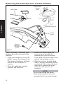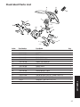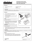
1
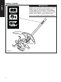
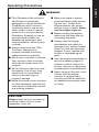
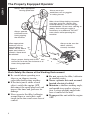
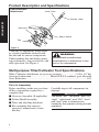
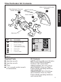
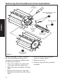
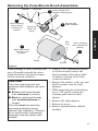
SHINDAIWA OWNER’S/
OPERATOR’S MANUAL
TILLER/CULTIVATOR
ATTACHMENT
WARNING!
Always wear eye and
ear protection when
operating this unit!
WARNING!
To minimize the risk of
injury to yourself and
others, read this manual
and familiarize yourself
with its contents.
䊛
Part Number 80465
Introduction
Contents
PAGE
The Shindaiwa Tiller/Cultivator
Attachment kits have been designed
and built to deliver superior performance and reliability without compromise to quality, comfort, safety or
durability.
As an owner/operator, you’ll soon
discover for yourself why Shindaiwa is
simply in a class by itself!
Attention Statements ........................... 3
Safety Labels ........................................ 4
Operating Precautions ........................ 5
General Safety Instructions ................ 7
Product Description ............................ 8
Specifications ....................................... 8
IMPORTANT!
The information contained in these
instructions describe units available
at the time of publication.
Kit Contents ......................................... 9
Assembly ............................................ 10
Operation ............................................ 16
Shindaiwa Inc. reserves the right to
make changes to products without
prior notice, and without obligation to
make alterations to machines previously manufactured.
Checking Unit Condition .................. 17
Shoulder Strap ................................... 17
Maintenance ...................................... 18
Troubleshooting Guide .................... 20
Illustrated Parts List .......................... 21
2
Attention Statements
WARNING!
A statement preceded by the
triangular attention symbol and the
word “WARNING” contains
information that should be acted
upon to prevent serious bodily
injury.
CAUTION!
A statement preceded by the word
“CAUTION” contains information
that should be acted upon to
prevent mechanical damage.
IMPORTANT!
A statement preceded by the word
“IMPORTANT” is one that possesses
special significance.
NOTE:
A statement preceded by the word
“NOTE” contains information that is
handy to know and may make your job
easier.
SAFETY
Throughout this manual are special
“attention statements”.
Read and follow this
manual. Failure to do
so could result in
serious injury.
Wear eye and hearing
protection at all times
during the operation
of this unit.
Beware of thrown
objects. Keep bystanders
at least 50 feet (15 M)
away during operation.
Do not operate this unit
if you are tired, ill or
under the influence of
alcohol, drugs or
medication.
IMPORTANT!
The operational procedures described in this manual are intended to
help you get the most from your
machine as well as to protect you and
others from harm. These procedures
are guidelines for safe operation
under most conditions, and are not
intended to replace any safety rules
and/or laws that may be in force in
your area. If you have questions
regarding your 230-series power tool,
or if you do not understand something in this manual, your Shindaiwa
dealer will be glad to assist you. You
may also contact Shindaiwa, Inc. at
the address printed on the back of
this manual.
3
Safety Labels
SAFETY
IMPORTANT!
Safety and Operation Information Labels:
Make sure all information labels are
undamaged and readable. Immediately
replace damaged or missing information
labels. New labels are available from
your local authorized Shindaiwa dealer.
READ THE
OPERATOR’S MANUAL.
WEAR HEARING AND ANSI Z87.1
APPROVED EYE PROTECTION.
KEEP AWAY FROM
ROTATING TINES.
Shindaiwa Inc.
Figure 1
4
80278
CULT01
Operating Precautions
SAFETY
WARNING!
■ This Shindaiwa tiller/cultivator
attachment is specifically
designed for use on Shindaiwa
PowerBroom and Trimmers.
Installation and/or use on any
other model, brand or type of
power tool is not approved by
Shindaiwa. Attempts to use on
non-approved models can
damage the equipment and
cause accidents, serious injury
or death.
■ Always make sure the Tiller/
Cultivator attachment is
properly installed and firmly
tightened before operation.
■ Never use a cracked or warped
tine: replace it with a serviceable one and make sure it fits
properly.
■ Never smoke or light fires near
the engine. Fuel is very flammable and fire could lead to
serious personal injury or
property damage.
■ Make sure there are no missing
or loose fasteners, and that the
stop switch and throttle controls
are working properly.
■ Make sure there is always
good ventilation when operating this unit. Fumes from
engine exhaust can cause
serious injury or death. Never
run the engine indoors!
■ Before starting the engine,
make sure the tines are not
contacting anything.
■ Always stop the engine
immediately and check for
damage if you strike a foreign
object or if the unit becomes
tangled. Do not operate with
broken or damaged equipment.
■ Stop the engine immediately if
the unit suddenly begins to
vibrate or shake. Inspect for
broken, missing or improperly
installed parts or attachments.
■ Never transport the unit or set
it down with the engine
running. An engine that’s
running could be accidentally
accelerated causing the tines
to rotate.
CAUTION!
Always keep the unit as clean as
practical. Keep it free of loose
vegetation, mud, etc.
5
The Properly Equipped Operator
SAFETY
Always wear appropriate
hearing protection.
Always operate
with both hands
firmly gripping
the machine.
Always wear eye
protection such as goggles
or safety glasses.
Wear close-fitting clothing to protect
your legs and arms. Gloves offer
added protection, and are strongly
recommended. Do not wear clothing or
jewelry that could get caught in
machinery or underbrush. DO NOT
wear shorts while operating this
machine.
Wear appropriate
footwear such as
nonskid boots or
shoes: do not wear
open-toed shoes or
sandals. Never work
barefooted!
Keep a proper footing and do not
overreach–maintain your balance at all
times during operation.
Always make sure the
debris shield is
correctly installed.
CULT02
Figure 2
Work Safely: Be Aware of the Working Environment
■ Be careful when operating on a
slope or on slippery terrain,
especially during rainy weather.
■ If the tines jam or strike a hard
object, switch the engine OFF,
disconnect the spark plug lead, and
inspect the tines and gearcase for
damage.
■ Never operate the tiller/cultivator
around vines or roots that could
tangle in the tines and cause loss of
control.
6
■ Do not operate the tiller/cultivator
in standing water.
■ Never operate this unit around
buried electrical cables!
■ Maintain a shallow working angle,
and avoid steep angles of operation. A steep working angle risks
loss of control of the unit.
■ Transport the unit with the engine
OFF.
General Safety Instructions
SAFETY
WARNING!
Never operate power equipment of any kind if you are tired or if you are
under the influence of alcohol, drugs, or any other substance that could
affect your ability or judgement.
WARNING! Minimize the Risk of Fire
Never smoke or light fires near the unit.
Always stop the engine and allow it to cool before refueling. Avoid
overfilling and wipe off any fuel that may have spilled.
Always move the unit to a place well away from a fuel storage area or
other readily flammable materials before starting the engine. Use caution
when handling fuel. Move the unit at least 10 feet (3 meters) from the
fueling point before starting the engine.
Never place flammable material close to the engine muffler.
Never run the engine without the spark arrester screen in place. Do not
operate the unit with the muffler removed.
WARNING!
Use Good Judgment
Always wear eye protection to
shield against thrown objects.
Always protect yourself from
hazards such as thorny brush and
flying debris by wearing gloves
and close fitting clothing that
covers arms and legs. Never wear
shorts. Don’t wear loose clothing
or items such as jewelry that could
get caught in machinery or
underbrush. Secure long hair so it
is above shoulder level.
Never run the engine indoors!
Make sure there is always good
ventilation. Fumes from engine
exhaust can cause serious injury
or death.
Always clear your work area of
trash or hidden debris that could
be thrown back at you or toward a
bystander.
Always stop the engine immediately if the unit suddenly begins to
vibrate or shake. Inspect for
broken, missing or improperly
installed parts or attachments.
Always hold the unit firmly with
both hands when tilling or cultivating, and maintain control at all
times.
Always keep the handles clean.
Always disconnect the spark plug
wire before performing any
maintenance work.
7
Product Description and Specifications
Tiller/Cultivator
Attachment
Outer Tube
Caution Label
DESCRIPTION
Gearcase
Debris Shield
Tine
CULT01
Figure 3
Using the accompanying illustrations
as a guide, familiarize yourself with
the unit and its various components.
Understanding this unit helps ensure
top performance, long service life, and
safer operation. See Figure 3.
WARNING!
Do not make unauthorized
modifications or alterations to this
unit or its components.
Multipurpose Tiller/Cultivator Tool Specifications
Tiller/Cultivator Attachment (w/gearcase & tines) ..................... 5.9 lbs. (2.7 kg)
Gearcase Lubrication ............................... Mobil SCH 634 synthetic gear lubricant
Gear Reduction ..................................................................................................... 40:1
*Specifications are subject to change without notice.
Prior to Assembly
Before installing, make sure you have
all the components required for a
complete unit:
䡵 Gearcase Assembly (If applicable)
䡵 Debris Shield Assembly
䡵 Tines and attaching hardware
䡵 Kit containing this owner's/
operator's manual and a 5 mm
hex key.
8
Carefully inspect all components for
damage.
IMPORTANT!
The terms “left”, “left-hand”, and “LH”;
“right”, “right-hand”, and “RH”; “front”
and “rear” refer to directions as
viewed by the operator during normal
operation.
Tiller/Cultivator Kit Contents
Debris Shield and Bracket
Assembly
Tiller/Cultivator Tine and
Holder Assemblies
1
3
DESCRIPTION
Plastic Sleeve
2
Gearcase
Item
No. Qty.
CULT03
Description
1
1
Debris Shield and
Bracket Assembly
2
1
Plastic Sleeve
3
2
Tiller/Cultivator Tine
and Holder Assembly
4
2
Clevis Pins
5
2
Hitch Pins
6
1
Caution Label
READ THE
OPERATOR’S MANUAL.
4 Clevis Pins
WEAR HEARING AND ANSI Z87.1
APPROVED EYE PROTECTION.
KEEP AWAY FROM
ROTATING TINES.
Shindaiwa Inc.
5
Hitch
Pins
6
80278
Caution
Label
Figure 4
Required Tools
Kit Contents
■ 4mm hex wrench
80275 (All PowerBrooms) Includes
Tines, Debris Shield, mounting
hardware and caution label.
99909-44000 (T230 T231 Trimmers) Includes Gearcase, Tines,
Debris Shield, mounting hardware
and caution label.
99909-55000 (T270 T272 Trimmers) Includes Gearcase, Tines,
Debris Shield, mounting hardware
and caution label.
■ 5mm hex wrench
■ Pliers
■ 7/16" wrench (socket wrench
recommended)
9
Removing the PowerBroom Drum Assemblies
Drum
Assembly
Remove hitch pins and
clevis pins
3
Remove cotter
pins
CULT04
ASSEMBLY
1
Gearcase
Output
Shaft
4
Slide off the
drum axles
2
Slide off drum
assemblies
Figure 5
Prior to installing a Tiller/Cultivator
Kit, the PowerBroom drum (if so
equipped) and axle assemblies must
be removed as follows:
1. Use a pair of pliers to remove the
cotter pins from the drum axles.
2. Slide the drum assemblies from the
axles.
3. Remove the hitch pins, and withdraw the clevis pins from the drum
axles.
10
4. Slide the drum axles from the
gearcase output shafts.
5. Remove gearcase.
6. Remove optional debris shield if
installed.
Removing the PowerBroom Brush Assemblies
Washer
End Cap
3
Drive out the shaft
adapter retaining pins.
1
Black retaining
bolt–counter
clockwise to
remove
Remove the
4 shaft adapters.
Brush not
shown for
clarity
2
Remove washers,
end caps and
brushes.
Silver retaining
bolt–clockwise to
remove.
1
Brush
CULT05
Washer
Figure 6
When installing a Tiller/Cultivator Kit
onto a PowerBroom with the nylon
brush attachment, the brushes must
be first removed as follows:
CAUTION!
The brush retaining bolts and
gearcase shaft adapters are colorcoded:
■ Silver for left-hand threads
(turn clockwise to loosen),
■ Black for right-hand threads
(turn counterclockwise to
loosen).
The bolts must be turned the
appropriate direction during
removal and installation. Failure to
do so could result in permanent
damage to the bolt and/or shaft
adapter.
1. Using a 7/16" combination wrench
or socket wrench, remove the
brush retaining bolts (silver bolts
clockwise to loosen, black bolts
counterclockwise).
2. Remove the washers, end caps, and
bristle brushes from the shaft
adapters.
3. While supporting the shaft adapter,
use a 3/16" punch to drive the
retaining pins from the shaft
adapter.
4. Remove the shaft adapters.
5. Remove gearcase.
6. Remove optional debris shield if
installed.
11
ASSEMBLY
End
Cap
Removing the Gearcase from a Grass Trimmer
Remove the
trimmer
head.
Shaft Tube
Shims
ASSEMBLY
Machine Screw (4)
Clamp
Screw
Remove
gearcase
locating
screw
CULT06
Figure 7
When converting a Shindaiwa grass
trimmer, the gearcase must first be
removed.
1. Using a hex wrench to secure the
holder, remove the trimmer head.
The trimmer head has a left-hand
thread, so turn clockwise to
remove.
2. Clean dirt and debris from the
gearcase and shaft tube.
3. Remove the debris shield and
gearcase as an assembly by
removing the gearcase locating
screw, then loosen the clamp screw
and the four machine screws.
4. Slide the gearcase from the shaft
using a twisting and pulling motion
as required. If necessary, the main
shaft can be removed from the
shaft tube with gearcase for
servicing.
NOTE:
Do not lose the the two shims.
They will be needed if the unit is
converted back to a grass trimmer.
12
Installing the Gearcase
WARNING!
When used with tiller/cultivator
tines, the PowerBroom gearcase
MUST be oriented with the
gearcase as shown. Failure to
correctly orient the gearcase on
the shaft tube could cause the
tiller/cultivator to be uncontrollable
during operation, risking serious
injury to the operator or bystanders!
CULT07
2. Slide the tiller/cultivator debris
shield onto the outer tube and over
the plastic sleeve. Orient the shield
so that its mounting bracket faces
upward as viewed while in operation. Use a 5mm hex wrench to
tighten the shield clamp securely in
place over the plastic sleeve.
See Figure 9.
3. If the mainshaft was removed
during disassembly, wipe the shaft
clean, lubricate shaft and spines
with a moly type grease and slide
the shaft into the outer tube until
the splines engage with the clutch
drum at the power head.
ASSEMBLY
1. Push the plastic sleeve over the
outer tube, and position the sleeve
approx. 4-1/2 inches from the end
of the tube. See Figure 8.
Position the
plastic sleeve
CULT08
Outer Tube
Approx. 4-1/2
inches
Figure 8
Debris shield
Outer
Tube
Mainshaft
CULT09
Tighten the
debris shield
clamp
Figure 9
13
Installing the Gearcase (continued)
IMPORTANT!
T260 GRASS TRIMMERS ONLY:
Tiller/Cultivator kits with a gearcase
(p/n 99909-55000) include a metal
spacer collar that must be installed
onto the outer tube before installing
the gearcase. Make sure the holes
for the locating screw align properly.
See Figure 10.
Spacer
Collar
CULT10
Outer
Tube
Figure 10
ASSEMBLY
4. Orient the gearcase on the shaft
tube with the output axles above
the tube clamp. See Figure 11.
5. Hand-thread the original gearcase
locating screw into the gearcase
and through the gearcase locating
screw hole in the outer tube. See
Figure 11. Tighten the screw
firmly.
Gearcase Locating
Screw
CULT11
Figure 11
6. Install the short screw on opposite
side.
Gearcase
Shim
7. Make sure the gearcae shim is
correctly installed in the gearcase
clamp then tighten the gearcase
clamp screw firmly. See Figure 12.
CULT12
Making sure the
gearcase shim is in
place, tighten the clamp
screw
Figure 12
14
Tine Orientation
Caution
Label
Clevis Pin
ASSEMBLY
Tine Assemblies
(hub faces in)
Hitch Pin
CULT13
Figure 13
Tine installation directly affects the
tiller/cultivator’s ability to break new
ground. Using Figures 14 and 15 as a
guide, determine the correct tine
orientation for the tilling/cultivating
job at hand:
1. Install the tine assemblies to the
gearcase output shafts.
WARNING!
Always switch the engine OFF
before working on the gearcase or
tines!
2. Secure each tine assembly with one
clevis pin and one hitch pin as
shown in Figure 13.
3. Apply the caution label to the outer
tube as shown in Figure 13.
Tilling/Digging in
Hard Soil
Weeding/Cultivating in
Softer Soil
Leading
Edge In
Leading
Edge Out
CULT14
Figure 14
Tiller Leading edge out for aggressive
action in hard soils.
CULT15
Figure 15
Cultivator Leading edge in for weeding or
turning softer soils.
15
Operation
Starting and Fueling
General Operation
For detailed instructions on general
safety procedures, fueling, starting,
and stopping the Shindaiwa
PowerBroom or Trimmer, refer to the
appropriate Owner’s Manual for your
model.
Your Shindaiwa Tiller/Cultivator's
reversible tines allow you to quickly
change from operation as a cultivatorweeder to an aggressive tiller for
quickly digging a new garden or
landscaping plot. For best operation in
either mode:
WARNING!
KEEP CLEAR of tines during
starting operations! The tines may
rotate during startup.
WATER the area to be tilled at least
24 hours before your planned tilling
operation; then water again about 3
hours before the actual tilling.
PULL the tiller slowly toward you
when tilling or cultivating.
OPERATION
FOR DEEP TILLING (up to 10"
depth) use full throttle while slowly
rocking the tiller back and forth
over the work area.
SHALLOW WEEDING in soft soils
is easiest when the tines are
installed in the cultivating configuration, with additional depth
available by using a gentle rocking
motion as described above.
HEAVY WEEDS or weeding in
harder soils may require reversing
the tines to the more aggressive
tiller configuration.
WARNING!
BURN DANGER! The gearcase
will become very hot during
normal operation.
16
Checking Unit Condition
NEVER operate the unit with the
debris shield or other protective
devices (ignition switch, etc.) removed!
WARNING!
A debris shield or other protective
device is no guarantee of protection against ricochet. YOU MUST
ALWAYS GUARD AGAINST
FLYING DEBRIS!
Shoulder Strap
NOTE:
Although a shoulder strap accessory is
not required for use with a Tiller/
Cultivator, a shoulder strap can
increase operator comfort during
extended periods of operation.
See Figure 16.
Shoulder strap
is available for
use with the
Tiller/
Cultivator.
Use only authorized Shindaiwa parts
and accessories with your Shindaiwa
machine. Do not make modifications
without the written approval of
Shindaiwa Inc.
ALWAYS stop the engine immediately
and check for damage if you strike a
foreign object or if the unit becomes
tangled. Do not operate with broken
or damaged equipment.
OPERATION
NEVER use a cracked or warped tine:
replace it with a serviceable one.
Figure 16
NEVER allow the engine to run at
high RPM without a load. Doing so
could damage the engine.
NEVER operate a unit with worn or
damaged fasteners or attachment
holders.
17
Maintenance
WARNING!
Before performing any maintenance, repair, or cleaning work on
the unit, make sure the engine and
cutting attachment are completely
stopped. Disconnect the spark plug
wire before performing service or
maintenance work.
WARNING!
Non-standard parts may not
operate properly with your unit and
may cause damage and lead to
personal injury.
NOTE:
Using non-standard replacement parts
could invalidate your Shindaiwa
warranty.
Daily Maintenance
MAINTENANCE
Prior to each work day, perform the
following:
■ Check for loose or missing screws
or components.
■ Make sure that nuts, bolts, and
screws (except carburetor adjusting screws) are tight.
18
Engine Maintenance
IMPORTANT!
For detailed engine maintenance
information, consult the owner's
manual that was provided with the
unit. If it has been lost or misplaced,
contact Shindaiwa for a replacement.
300-hour Maintenance
Gearcase Lubrication
Fill to
this level
The gearcase should be filled with 60
cc (2.0 fl.oz.) of Mobil SHC634
Synthetic Gear Oil. A maximum of 7580 cc can be used; but never to exceed
80 cc. Operation with excessive oil
level will result in high operating
temperatures. Do not overfill!
0.60"
15.5 mm
CULT18
Figure 18
4. Turn the gearcase to the RH side
and and allow all used gearcase oil
to drain into a small container.
CULT17
Figure 17
Replacing the gearcase oil
WARNING!
1. Disconnect spark plug wire at
engine.
6. Inspect the sideplate for damage
and clean off all remaining liquid
gasket material with brake cleaner
or acetone. Coat the outer sealing
flange of the sideplate with Loctite
Ultragrey Silicon Sealant or
Threebond No. 1104 Liquid
Gasket.
2. Remove the RH tine and holder
assembly (as viewed from the
operating position). Wipe the
sideplate clean and remove four
screws (it is not necessary to
7. Replace the cover and install the
remove the gearcase from the outer
four sideplate screws. Tighten
tube).
securely.
3. Turn gearcase side plate to break
8. Reinstall the tine and holder
the seal and lift the plate from the
assembly with the clevis pin.
gearcase. See Figure 17.
Secure with hitch pin.
NOTE:
It may be necessary to use a heat gun
to soften the sealer material.
19
MAINTENANCE
BURN DANGER! The gearcase
will be extremely hot after use!
5. Place the gearcase on the LH side
and supported so the outer tube is
parallel to the ground. Refill the
gearcase with 60 cc (2.0 fl.oz) of
Mobil SHC634 Synthetic Gear Oil
to the bottom of the chamfer on the
output gear. The correct oil depth
is 0.60" (15.5 mm). See Figure 18.
DO NOT OVERFILL!
Troubleshooting Guide
ADDITIONAL PROBLEMS
Symptom
Excessive
vibration.
Possible Cause
Remedy
Warped or damaged
tines.
Inspect and replace
tines as required.
Loose gearcase.
Tighten gearcase securely.
Bent main shaft/worn or Inspect and replace
as necessary.
damaged bushings.
Tines will not
rotate.
Tines rotate at
engine idle.
TROUBLESHOOTING
20
Shaft not installed
in coupler or
gearcase.
Inspect and reinstall
as required.
Broken shaft.
Consult with an authorized
servicing dealer.
Damaged gearcase.
Consult with an authorized
servicing dealer.
Engine idle too high.
Adjust engine idle speed
2,750 RPM. (Ⳳ250 ) RPM (min-1)
Broken clutch spring
or worn clutch spring
boss.
Replace clutch spring
and shoes as required.
Illustrated Parts List
11
8
OP
ERA REA
TOR D
’S THE
MA
NU
AL.
WE
AP AR
PR HEA
OV RIN
ED G
EYE AN
PR D AN
OTE SI
CTI Z8
ON 7.1
.
KE
Shin
daiw
RO EP
a Inc.
TAT AW
ING AY
FRO
TIN
ES. M
802
78
14
7
3
9
5
12
13
6
10
4
2
1
3
CULTIPL
Part Number
78822-01110
12400-16088
78822-01120
78822-01130
01011-06128
78822-01140
78822-01150
78822-01160
78822-01170
78822-01180
78822-01190
72959-13330
22222
33333
80278
Part Name
LOCK PIN
SNAP PIN
TINE
TINE HOLDER
TINE HOLDER SCREW
DEBRIS SHIELD BRACKET
DEBRIS SHIELD HOLDER
DEBRIS SHIELD
COLLAR
SHIELD BRACKET SCREW
SHIELD HOLDER SCREW
SPACER COLLAR (T230, T231, T2500, T260, T261)
GEARCASE (T230, T231, T2500)
GEARCASE ( T260, T261,T270, T272)
CAUTION LABEL
Qty.
2
2
2
2
6
1
1
1
1
2
4
1
1
1
1
21
PARTS LIST
Index
1
2
3
4
5
6
7
8
9
10
11
12
13
13
14
NOTES
䊛
Shindaiwa Inc.
11975 S.W. Herman Rd.
Tualatin, Oregon 97062
Telephone: 503 692-3070
Fax:
503 692-6696
www.shindaiwa.com
Shindaiwa Kogyo Co., Ltd.
6-2-11 Ozuka-Nishi,
Asaminami-ku, Hiroshima,
731-3167, Japan
Telephone: 81-82-849-2220
Fax:
81-82-849-2481
䊚2002 Shindaiwa, Inc.
Part Number 80465
Revision 8/02
Shindaiwa is a registered trademark
of Shindaiwa, Inc.
Specifications subject to change without notice.