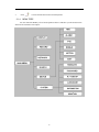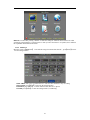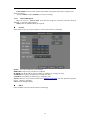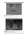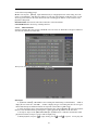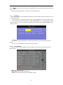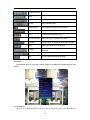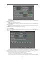
1
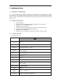
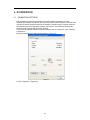
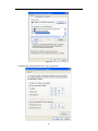
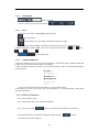
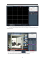
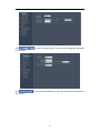
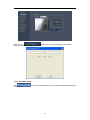
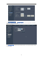
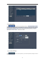
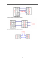
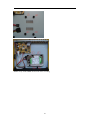
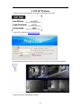
H.264 NETWORK Embedded
DVR
USER MANUAL
2
CONTENT
1.
INTRODUCTION ........................................................................................................................................ 4
1.1.
PREODUCT INTRODUCE ................................................................................................................... 4
1.2.
PRODUCT FEATURE .......................................................................................................................... 4
1.2.1.
SPECIFICATION .......................................................................................................................... 4
1.2.2.
BASIC WORKING PARAMETER .................................................................................................. 5
1.3.
ENVIRONMENT ADAPTABILITY .................................................................................................... 5
2.
DEVICE OPERATION ............................................................................................................................... 6
2.1.
REMOTE KEY INSTRUCTION ........................................................................................................... 6
2.1.1.
REMOTE CONTROL .................................................................................................................... 6
2.1.2.
Use Remote controller to select the device number: ..................................................................... 6
2.1.3.
MOUSE OPERATION ................................................................................................................... 7
2.1.4.
MENU TREE ................................................................................................................................. 8
2.2.
SYSTEM OPERSTION ......................................................................................................................... 9
2.2.1.
USER LOGIN ................................................................................................................................ 9
2.2.2.
GUI OPERATION ......................................................................................................................... 9
2.2.3.
DEVICE SETUP .......................................................................................................................... 18
2.2.4.
SYSTEM SETUP .......................................................................................................................... 23
3.
IE OPERATION ........................................................................................................................................ 28
3.1.
CONNECTION SETTINGS ................................................................................................................ 28
3.2.
FEATURE ........................................................................................................................................... 30
3.3.
USER LOGIN ...................................................................................................................................... 30
3.4.
OPERATION INTERFACE ................................................................................................................ 31
3.4.1.
LIVE............................................................................................................................................. 31
3.4.2.
REPALY(IE Browser) .................................................................................................................. 32
3.4.3.
REMOTE SETTING ..................................................................................................................... 34
3.4.4.
LOCAL SETTING ........................................................................................................................ 42
3.4.5.
LOGOUT ..................................................................................................................................... 43
3.5.
PRODUCT OVERVIEW ..................................................................................................................... 43
3.5.1.
The Definition of Buttons and Connectors on DVR Front Panel................................................. 43
3.5.2.
DVR rear board interface definition............................................................................................ 43
3.6.
ALARM POST INTERFACE (OPTIONAL) ................................................................................................... 44
Alarm Input and Output ............................................................................................................................... 44
System Network Diagram ............................................................................................................................. 46
3.7.
HDD INSTALLATION ....................................................................................................................... 46
4. FAQ .................................................................................................................................................................. 47
5. P2P DIT PLARTFORM ................................................................................................................................ 50
3
1. INTRODUCTION
1.1. PREODUCT INTRODUCE
The series of DVR include 4 channels,8 channels and 16 channels ,this is 4CH digital video recording
DVR, which have local recording, playback, support triple code remote network surveillance, data backup,
parameter setting, motion detection, I/O alarm setting, PTZ and USB mouse, USB2.0 backup, IE browser
and back up etc.
1.2. PRODUCT FEATURE
H.264 compression
Two USB interface, USB2.0 for data backup, USB2.0 for mouse operation.
Support 1 pcs 3.5” SATA HDD at most.
Special file system for security.
16 bit color translucent user-friendly GUI, with notes for selected menu items
Optimized one four channel simultaneously playback
Double level user management
Support the live view, parameter setting and copy playback video via network.
1.2.1. SPECIFICATION
4CH DVR specification
Module
Picture
compression
4CH
H.264
Video in
1.0Vp-p/75Ω,BNC×4
Video out
1.0Vp-p/75Ω,BNC×1;VGA×1
Resolution
Live:D1
Record:4CH D1
Frame rate
PAL :100 Fps(CIF)
NTSC :120 Fps(CIF)
Audio input
RCA×1
Audio output
RCA×1
Audio codec
G.711A
Video mode
Manual recording , Scheduled recording,Movement alarm video and External
alarm recording
Network interface
PTZ
communication
interface
Data storage
RJ45,100M/1000M
support
RS485×1, USB2.0×2
Support 1 SATA HDD(300GB-2TB)
4
Mouse
Remote control
voltage input
USB Mouse
Support
DC12V/5A
1.2.2. BASIC WORKING PARAMETER
Item
Parameter
Description
Voltage input
12V
DC 12V
Video impedance
input
75Ω
75Ω Each channel.
Video output
1Vp-p
1Vp-p CVBS signal
RS485
Connect to PTZ, (Pelco-D,Pelco-P)
SATA HDD
One SATA HDD (up to 2T)
1.3. ENVIRONMENT ADAPTABILITY
1)
2)
For safety while using the DVR and to prolong device life, please pay attention to the
following details:
When installing device, please comply with all the electric product safety criteria.
Power and ground:
Do not touch the power and DVR with a wet hand
Do not drop liquid on DVR
Do not put any object on DVR
Please use soft dry cloth to clean DVR; do not use chemical impregnant.
The Device will have voltage before startup if the power line is connected to power
Source.
Please unplug power line from power source if the Device is not intended to be used
for a prolonged time.
5
2. DEVICE OPERATION
In device operation, the enter key on remote control has the same function as left click of the mouse.
2.1. REMOTE KEY INSTRUCTION
2.1.1. REMOTE CONTROL
The remote control is the secondary input device
For navigating the system’s interface.
To use the remote control:
1. STANDBY: Press to turn on/off standby mode.
2. LOGIN/LOCK: Remote control can control the device through the
device number is landing, Locked shielded remote control equipment
3. Number/Channel buttons: While in menus,
press buttons 0~9 to enter values; during live
viewing, press to view channels in full-screen.
4.
: Press to switch between quad and
split-screen displays.
5. MENU: Opens the main menu.
6. PTZ: Press to open the PTZ control window.
7. EXIT: Close menu windows.
8. Navigation/OK:
• : Move cursor in menus up,Channel Up
• : Move cursor in menus right,Channel Up, during
playback, increase forward playback speed (2X, 4X,
8X,16X,32X).
• : Move cursor in menus left, Channel down, during playback,
increase reverse playback speed (2X, 4X, 8X,16X,32X)
• : Move cursor in menus down, Channel down
• OK: In menus, press to confirm selections;
9. +/ - : In menus, press to adjust values.
10. RECORD: Press to start manual recording.
TIP: When using the remote control to
11. STOP: Press to stop manual recording.
enter password and camera titles,
12. EXTRA: For the future use.
select the field using the navigation
13. Playback controls:
buttons press ENTER, and then press
• : Increase reverse playback speed 2X, 4X, 8X,16X,32X;
the number buttons.
• : Press to start playback;
• : Press to increase forward playback speed 2X,4X, 8X,16X,32X;
•
: Press to slow playback speed by 1/2, 1/4, 1/8, 1/16,1/32;
•
: Press to freeze playback to one frame, then press again to advance frame-by-frame
14.AUDIO/MUTE: Turn on/off audio
2.1.2. Use Remote controller to select the device number:
Press 【LOGIN/LOCK】 key, and enter device number, then you can control the device by this
remote control. (Device number is available in 【PASSWORD】)
For example. Select the device with number "000001".
Press 【LOGIN/LOCK】+【1】,then the remote controller can control this device.
Remark:
1. Remote controller can control the device with number"000000" as default.
6
2. If press【LOGIN/LOCK】+【0】, then the remote controller can control device with any number.
3. The number of device should be smaller than 000255.
2.1.3.
MOUSE OPERATION
The mouse is the primary input device for navigating system menus.
NOTE: Unless otherwise noted, all system functions described in this manual are achieved through
mouse input.
To use a mouse with the system:
1) Connect a USB mouse to the USB MOUSE port on rear panel of the system.
NOTE: Only the top USB port on the rear panel is designed for data backup to a USB flash drive. Do
not connect a USB flash drive to the bottom USB port on the rear panel.
Figure 1.0 Connect a USB mouse to the bottom USB port on the rear panel
2)
3)
Use the mouse buttons to perform the following:
• Left-Button: Click to select a menu option;
during live viewing in split-screen, double-click
on a channel to view the selected channel in
full-screen.; double-click the channel again to
return to split-screen view
• Right-Button: In real-time preview, Right-click
a menu list, select the main menu to enter the
system menu, The menu page, click the right
mouse button to return to the previous
Scroll-Wheel: No function.
Figure 1.1 Mouse button operation
When using the mouse, you can input certain values using the onscreen virtual keyboard.
You will need to use the Virtual Keyboard when entering your User ID and Password.
4)
Virtual Keyboard (Mouse)
To use the Virtual Keyboard:
1.
Click on an option or field, such as the User ID and
Password fields.
2. Click 0~9 to key-in the desired digit.
3.
Click
to switch between numerals, upper and
lowercase letters, and other characters (Different input box has a
different input method switch)
4. Click
to Backspace/Delete.
NOTE: The buttons will turn from orange to white when you select the button with the mouse cursor.
7
5.
Click
2.1.4.
to enter/confirm and close the Virtual Keyboard.
MENU TREE
You can control the DVR by a lot of menu operation. This tree will show you the menu structure
and it will be in details in after chapter.
8
2.2.
SYSTEM OPERSTION
2.2.1. USER LOGIN
2.2.1.1 STARTING THE SYSTEM
To power the system ON/OFF:
Connect the power cable to the DC 12V port on the rear panel. At startup, the system performs a basic
system check and runs an initial loading sequence. After a few moments, the system loads a live display
view.
ATTENTION: By default, passwords are disabled on the system. You do not need to enter a
password when accessing any system menus. However, for security purposes, it is highly recommended to
enable passwords on the system using the Password Menu.
NOTE:
1) If there is no HDD in device, or the device didn`t read the HDD, or the HDD didn`t be formatted
it will display an 【H】 in the video preview interface.
2) You must format the HDD in the DVR before first using. The steps as follows: Main Menu >
Device>HDD management > format. After formatting, the system will restart.
2.2.1.2 SYSTEM LOGIN
Login the main menu: Right-click anywhere on the screen, it will pop-up a menu list, then select [main
menu]; If use remote controller or front panel, just press [MENU] button.
Username: Click the User Name drop-down box, select your user name. If you want to register another
user to login, please select [admin] to login, and choose:[Main Menu]-[System]-[Password], to open the
another user.
Password: Enter the correct password.
Note: The default system password is enabled, every time you boot into the system requires you to enter
the password for the user name to enter the system. (System Administrator [admin] default password is:
123456), or (default password of [user1] is: 123456)
2.2.2.
GUI OPERATION
The main menu include “DISPLAY”, “RECORD”, “NETWORK”, “SEARCH”,“DEVICES”,and
“SYSTEM”.
9
Remark: You must after pressing “APPLY” to make the setting for submenu valid. It will no use when
exit directly. This DVR have a special feature is: when you move the mouse to everywhere, there will have
the explanation information showed auto.
2.2.2.1 DISPLAY
Move the cursor to【DISPLAY】(Icon with the orange box means that selected), press【Enter】to enter
into the setting interface.
CH01~CH04: click to pop up pull-down box to switch to other channel to carry out setting.
CHN NAME: press【Enter】to enter into the setting interface.
POSITION: press【Enter】 to switch name location, there are 5 options.
COLOR: press【Enter】to enter into setting interface, as following:
10
Press【Enter】or【+】【-】key or directly drag the cursor to set colors, including chroma,
brightness, contrast and saturation, press【APPLY】to save the parameters.
Cover: Click on the [Mask] button to enter this channel preview screen editing block area, Live drag
the left mouse button to edit the block area, Then right click menu, select [Save] button to edit the
entry into force, This channel preview block region black display, as shown:
LIVE: ON: Means the channel is allowed to view the live mode, OFF means not.
11
LIVE TIME(display time while in live view)): ON: Means yes, OFF means not.
RECORD TIME(display time while recording): ON: Means yes, OFF means not.
2.2.2.2
RECORD SETUP
Move the cursor to 【RECORD】(Icon with the orange box means that selected),press【Enter】to
enter into the setting interface. Press【Confirm】 and enter into the setup interface, and you can use
direction keys and cursor to change the options.
CH01~CH04: click to pop up pull-down box to switch to other channel to carry out setting.
RECORD: ON: Means the channel enable for recording. OFF means not enable.
QUALITY: There are three options, corresponding different data stream standard.
FRAMERATE: Can set 1-30frame
RESOLUTION: CIF.
AUDIO: ON: Means enable the audio recording for all channels, OFF: Means disable audio recording
REC.MODE:
Always: Means the device will start recording when it startup.
Schedule: Recording as the schedule, you can setup the schedule as you want as follow.
CHANNEL: You can select all channels or just one channel to setup schedule.
WEEKLY: You can setup each as you want. There are ALARM, NORMAL, NO REC three modes, if
you select this, there will have a √ in the frame, that means when you select the period of the day it will
record as this mode, and you can just setup one day, then copy the setting to all other days. Different color
means different record mode: Red means alarm record, green means normal record, grounding means no
record.
12
PACK TIME: There are 15min, 30min, 45min, 60min four options, that means it will pack as the
mode you selected
Scroll to APPLY and press ENTER to save the new settings.
2.2.2.3
NETWORK SETUP
Move the cursor to 【NETWORK】 (Icon with the orange box means that selected), and press
【Enter】 to enter into setting interface .
TYPE: There are DHCP & Static three options.
●
STATIC
Select [Static] in the type, and press [Enter] to enter into the interface as followings
PORT:
: For video transmission via IE/CLIENT.
WEB PORT: setup the port of IE browser via HTTP.
IP ADDR: setup the IP address, and press [Enter] or number keys to change the value.
NETMASK: press [Enter] or number keys to change the value.
GATEWAY: press [Enter] or number keys to change the value.
E-Video:
:The user can review the DVR IE from : http://ie.scc21.com .(For more operation step please
refer to Chapter V appendix)
UPNP: Universal Plug And Play
●
DHCP
Select the DHCP, and enter into the interface as followings.
13
PORT: the communicate port between PC and DVR, recommend use default port.
WEB PORT: setup the port of IE browser via HTTP.
Remark: when you setup the net mode as DHCP, the router will arrange a dynamic IP for DVR.
UPNP: Universal Plug And Play, the router will auto forward the DVR port
MEDIA PORT: the communicate port between PC and DVR, recommend use default port
WEB PORT: setup the port of IE browser via HTTP.
MOBILE PORT:
:the port for mobile view, you should open the port in the router for mobile view. Please
note that the server port of DVR must with the same port of mobile .
PPPOE username and password: fill the username and password of the internet service offer, and apply
it and reboot the system. After rebooting, the device will save it and set the PPPOE as default network type.
14
If succeed, the IP address will be automatically config as dynamic IP of WAN.
DDNS: There are [ON/OFF], and if there is a DDNS service, please setup it as ON.
Server: User can select required DDNS server, there are 4 options: 3322, dyndns,nightowldvr,no-ip.
Domain NAME: Input the name of the host server.
USERNAME: Input in the name of the user.
PASSWORD: Input the password for DDNS.
2.2.2.4
SEARCH
Move the cursor to 【SEARCH】(Icon with the orange box means that selected),press【Enter】
to enter into the setting interface.
DATE: You can adjust the checking date and time, press【Enter】 input the number directly to adjust the
year,month,date.After finishing the time setting, move the cursor to “SEARCH” and press”APPLY”,can
see the recording status of this date. As follow:
Instruction:
1. MONTH: It will show all the recording status in this month. Green means normal recording, Red
means alarm recording, Grounding means no recording. Click any date in this frame can search the
recording status of that day, the searching result will be showed in the below date frame.
2. DAY: It will show all the recording status in this day, you can playback the record file in this period
15
via click the corresponding period.
PLAY: You can press 【Enter】 input number directly to setup playback time. After setting, move the
cursor to “PLAYBACK”, and then press”APLLY”to enter into video playback of that time. Also you can
select any period of time in the video status frame after searching,press”APLLY”to enter into the video
playback of this period.
DETAIL FILES: Enter into the video file list interface of the selected date.
LOG SEARCH: Enter into the log searching interface.
2.2.2.5
DETAIL FILES
Setup the searching date, after pressing “SEARCH”,move the cursor to “Detail files” and press”APPLY”to
enter into the video file list of this date.
Then you can select four channels as you want to playback.
Instruction:
1. 【DETAIL FILES】,“CHANNEL”is the recording file which belong to which channel, “SIZE” is
display the size of this file(Unit:MB), “TYPE” is display the type of recording file, there are two types:
normal and alarm,press“BACKUP”button can export the selected files to USB storage;
2. After moving the cursor up and down and select the files, and press【APPLY】to enter into playback
interface. If the all channels have recording files, it will be playback all windows at the same time.
3. If setup as “Open” in the【RECORD TIME】in 【DISPLAY】, it will show the date/time when
playback record file; If setup as “Close”it will not display time.
4. When playback, can press【 】to play slowly; press【 】and【 】to speed、reverse play; also
16
can press【 】to pause and frame by frame play; Press【Exit】to exit from playback and return to the former
menu;
5. When finished playback files, it will return to the file list interface.
2.2.2.6
BACKUP
You can use USB for backup, should insert USB device into the USB2.0 port before backup files. And
it is support USB OTG.
You can select the recording file by direction keys, and press【Enter】means selected OK(There is
a “√” at the end of the selected recording files)and press 【Enter】again the “√” will disappear that means
cancel the select, we can start export the recording files after selecting, and press【BACKUP】to start to
backup, as follow:
Instruction:
1.
.When the space in backup device less than recording file, the system will prompt “Space no
enough”.
2.
.You can move USB device directly when backup finished.
2.2.2.7
LOG SEARCH
Move the cursor to “LOG SEARCH” and press”APPLY”to enter into the log file list of DVR, as
follow window.
INFO: means the alarm type.
TRIGGER: means the alarm triggered time.
VIDEO: means whether the log has corresponding video file.
17
2.2.3. DEVICE SETUP
Move the cursor to【DEVICE】(Icon with the orange box means that selected),press【Enter】to enter
into setting interface.
Advanced Features include HDD, ALARM, PTZ, MOBILE and MOTION DETECT.
2.2.3.1 HDD MANAGE
Move the cursor to 【HDD】(Icon with the orange box means that selected),press【Enter】to enter
into the setting interface, and you can use direction keys and cursor to change the options.
HDD STATUS: There status is ok means the HDD is ok. If HDD can not run normally(including
unformat and no HDD), there is a【H】display on video live view, DVR can support 1HDD at most.so you
can select the HDD you want to format here.
OVERWRITE:AUTO: means when HDD space less than 4G, it will delete HDD earliest recording file,
and it will stop deleting when the space is 10G; OFF: means when HDD space less than 500M it will stop
recording,also can set DVR auto delete video after 1hour/3hour/1day/7day/30day.
Format HDD: Move cursor there to select device and press【APLLY】 to start formatting.
Format USB: format the external thumble drive.
2.2.3.2 ALARM SETUP (Optional)
Move the cursor to【ALARM】(Icon with the orange box means that selected),press【Enter】to enter
into setting interface.
18
CH01~CH04: click to pop up pull-down box to switch to other channel to carry out setting.
I/O ALARM: Each channel has an I/O status, that is, when an alarm triggered, it will activate the
corresponding channel to start alarm recording.
N.O: indicate I / O input level from high to low effective
N.C: indicate I / O input level from low to high effective
HDD LOSS:ON means it will trigger a alarm if there is no HDD, and it will display an 【H】
On the bottom left of channel 1 in the live view
No Space: ON: If the space less than 500M, there is a remark in live view: No enough space, please
change HDD after shutdown.
VIDEO LOSS: ON: when one channel has no video input, it will display “video loss”in live view.
ALARM CONTRL: There are alarm output, buzzer Durationand pre Rec four items.
● OUTPUT: when an alarm triggered, the alarm output time will be:
0 second、10 seconds,20 seconds,40 seconds and 60 seconds
● BUZZER: buzzer calling time setup when alarm triggered:OFF,10 seconds,20
seconds,40 seconds and 60 seconds
● DURATION.:post recording time setup: 30 seconds,1 minute,2 minutes and 5 minutes
● PRE REC:OFF/ON
2.2.3.3 PTZ SETUP
Move the cursor to【PTZ】(Icon with the orange box means that selected),press【Enter】to enter into
setting interface, you can setup the parameters for each channel separately.
CH01~CH04: click to pop up pull-down box to switch to other channel to carry out setting.
PROTOCOL: select the protocol of different PTZ, there are two protocols to switch, and the default is
Pelco-D
BAUD RATE: select the different baud rate for your PTZ, there are 1200, 2400, 4800, ,9600,38400,57600
and 115200.
DATA BIT: there are 5,6,7,8 options to select, default setting is 8.
STOP BIT: there are 1and 2 to select, the default setting is 1.
PARITY: there are None/Odd/Even/Mark/Space to select, the default setting is none.
CRUISE: ON means open the scanning auto-cruise function for corresponding channel,
OFF means not open
ADDRESS: Fill the code of respective PTZ
19
PTZ Control
1.
2
3
All Functions
Pointer
Auto Pan
To select the direction of PTZ
The middle circle is for auto pan of PTZ.
20
Zoom in/zoom out
Focus
Iris
Volume
PTZ control the speed
Channel select
For selecting the channels of PTZ camera.
Cruiseset
To cruise setup
Exit
To back to previous page or exit
Go to preset point
Allow you to go to a specific preset point.
Set Ponit
Allow you set a set of specific preset points of a PTZ
camera. Also it can Adjust the camera in a fix point.
Clear
Allow you to delete the selected preset
Curoint
It indicates the starting point cruised. System default
point is 01.
Holdtime
Sets the stop time at each point
Save
Save the changed and the preset point.
Cruise(PTZ)
This function allows to start cruise of PTZ camera.(
(accouding the presetting point to autocruise)
)
2.2.3.4 MOBILE
Move the cursor to【MOBLE】(Icon with the orange box means that selected),press【Enter】to enter
21
into setting interface.
PORT: the port for mobile view, you should open the port in the router for mobile view. Please note
that the server port of DVR must with the same port of mobile .
Network: Select different mobile network from the options of WIFI, 2.5G, 2.7G,3G and WIFI, and
press [Enter] to switch different network.
2.2.3.5 MOTION DETECT
Move the cursor to【MOTION】(Icon with the orange box means that selected),press【Enter】to enter
into setting interface.
CH01~CH04:click to pop up pull-down box to switch to other channel to carry out setting.
STATUS: Each channel has corresponding channel switch, press 【Enter】to turn on or turn off the motion
detection for each channel..
SENSITIVITY:Each channel has corresponding sensitivity setting, including four standards
highest,high,middle and low, press【Enter】key to switch
MD AREA: each channel has corresponding regional motion detecting setting, move the cursor to
corresponding 【setting】,press【Enter】to enter regional setting interface, red area means it have activated
motion detection, transparent block means it have not activated motion detection.
22
Move the direction key on remote control to make cursor move in the small pane, green frame
means the cursor has moved to this pane, press【Enter】to select or cancel motion detection of this small
pane, when setup finished, press【exit】to back to MD setup interface, it will save automatically.
Remark:
IR Operation: press [Menu] key to select or cancel the entire screen.
Mouse operation: click left and drag the frame to setup the region for motion detection.
2.2.3.6 EXIT
Move the cursor to【EXIT】(Icon with the orange box means that selected),press【Enter】to back
to main menu.
2.2.4.
SYSTEM SETUP
Move cursor to select【SYSTEM】 (Icon with the orange box means that selected)and press【ENTER】
to enter into the system language setup interface.
System setups include time/date, password, video/audio, language, info and maintain six options.
2.2.4.1 DATE/TIME SETUP
Move cursor to select【TIMEDATE】(Icon with the orange box means that selected)and press
【ENTER】to enter into the date/time setup interface.
23
DATE: Setup system date via numeric key.
DATE FORMAT: Press ENTER to switch between the date patterns, there are YY-MM-DD and
MM/DD/YY two options.
TIME: Setup system time via numeric key.
TIME FORMAT: Press ENTER to switch between the date patterns, there are 12 HOURS and 24
HOURS two options.
Remark: You must press 【APPLY】 to save it, otherwise it won’t save the modify if you exit this
interface.
DST: DST settings, you can setup DST as you want here.
2.2.4.2 PASSWORD
Move the cursor to【PASSWORD】(Icon with the orange box means that selected), press【Enter】to enter
into the setting interface.
Device ID:Press figures to set Device ID directly. After finished, if you want to control DVR by
remote controller, you need to press [Login/Lock]+ Device ID first, then you can control it by remote
controller.(Please check Chapter Three for the introduction of remote controller.)
User ID:Press [OK] to select user ID, it supports 5 User IDs.
User Name:You can change user name here. (Note: admin can not be changed)
Password:Enter figures to set your passwords. (Note: max 6 figures; System Administrator [admin]
24
default password is: 123456), default password of [user1] is: 123456)
User Right:[Control PTZ]: Have right to control PTZ
[Config. Argum.]: Have right to change system parameters settings.
[System Maintain]: Have right to maintain systems(Such as system upgrade, system
default )
control channel: control channel whether to display the image preview of IE browser,When checked,
the channel image,Does not display when not checked
2.2.4.3 VIDEO/AUDIO SETUP
Move the cursor to【A/V SETUP】(Icon with the orange box means that selected),press【Enter】
to enter into setting interface.
VIDEO SYSTEM: press【Enter】to switch camera system, has PAL and NTSC two options
POLL TIME: the interval for channel loop function
SEQUENCE: you can setup the channel sequence as you want here.
VGA RESOLUTION: press 【 Enter 】 key to setup the VGA resolution, there are
1024*768,1280*1024,800*600 four options.
Alarm full screen: open the channel motion detection alarm screen full screen
VOLUME: move cursor to【VOLUME SETUP】,press【Enter】to enter into volume setup interface,
press number keys or directly drag the cursor to adjust volume.
Remark: it will restart if you modify the Norm(video system) or VGA resolution.
2.2.4.4 LANGUAGE
Move cursor to select 【LANGUAGE】(Icon with the orange box means that selected)and press
【ENTER】to enter into the system language setup interface.
25
System language have
Chinese ,English ,Russian ,Portuguese ,Spanish ,Turkish ,Italian ,Persian ,French and Polish ten options,
you can setup the language you want in here.(Different versions of the language there will be differences)
Remark: The device will restart when you setup system language success.
2.2.4.5 SYSTEM INFO
Move the cursor to 【INFOMATION】(Icon with the orange box means that selected),press【Enter】
to enter into setting interface, at this interface mainly display system hardware features and firmware
version, include : Device ID, Software Ver and MAC Address.
2.2.4.6 SYSTEM MAINTAIN
Move the cursor to 【MAINTAIN】(Icon with the orange box means that selected), and press【Enter】
to enter into system maintain setup interface.
26
AUTO MAINTAIN: When switch is on, you can setup the time for device to restart.
SYSTEM UPDATE: Copy the update file to the “dvrupgrade” folder in the root directory of the
thumb driver, and insert it into USB 2.0, then press [Enter] to upgrade the firmware, and it will display the
process of the system upgrading, as following.
REBOOT: means restart the device.
POWER OFF: The button allows to shut down the system from OSD.
27
3. IE OPERATION
3.1. CONNECTION SETTINGS
DVR through the remote access network, local area network connection, the client
computer's IP address must be with the DVR at the same network segment, in the wide area
network connection through the dynamic IP address or domain name to connect, when the
two sides need to ensure that public network can access it. The following introduces the
method of local area network connection settings:
1.right-click "My Network Places" in the pop-up menu, click on "Properties", open "Network
Connections."
2.Double-click open the "Local Area Connection." (Figure 8-3)
Figure3-3
3. Click "Properties." (Figure 8-4)
28
Figure 3-4
4. Double-click "Internet Protocol (TCP / IP)". (Figure 8-5)
29
Figure3-5
5. See PC's IP address, subnet mask, default gateway. (Figure 8-5 in the parameters
depending on the specific circumstances of different users)
6. DVR set up the corresponding IP address, subnet mask, and default gateway (see
section 6.5 Network Settings). DVR which the subnet mask, default gateway and the PC the
same as, IP address must be in the same network segment, but you can not have been
used with the same IP address, or IP addresses will result in conflict. The above map for
example, IP address should be: 192.168.0.X, in which X is not 40 or 1 (including the other is
using the IP address), and can not be more than 255, the subnet mask is 255.255.255.0,
gateway to 192.168.0.1.
3.2. FEATURE
Through the IE browser of OS and install the software, you are able to do the network operation
remotely, which is much more convenient. DVR support C/S, B/S, and visit in LAN and WAN, also
support IP and domain name visiting.
Remark: Operating system Windows XP, Windows Vista and Browser IE6.0, IE7.0 is recommended
3.3. USER LOGIN
Input the DVR local IP in IE browser, when changed the port, you should add the port number after
IP address, e.g. if DVR local IP is 192.168.1.118 (LAN) and the port is 8088, you should input 1http://
192.168.1.118:8088. The default port is 8088, and directly input http:// 192.168.1.118 to access the login
interface as following.
Select English interface in the top left side. Input username and password to enter into the
system. The username and passport is same as the ones set in DVR,Sign in IE must enter a
user name and password to log in, the user name and password consistent with the DVR,the
default administrator user: admin, the corresponding password is: 123456,
PASSWORD: Administrator has all authorities, operator has limited authorities who they can
only watch, playback, please change the unit No. and default password is blank.
NETWORK: LAN/INTERNET(WAN)
30
Remark: If you connect the device in WAN, the IP should be a public IP.
3.4. OPERATION INTERFACE
There are Live view, Playback and Setup options in the main interface, please press them to access it.
3.4.1. LIVE
Click
to enter into the interface as followings
3.4.1.1 PTZ CONTROL
Change the focus, preset aperture to control the PTZ.
Click
to up/down/left/right control movement of the PTZ. When hold on the one
direction key, the PTZ will keep circling as that direction after user press the stop key in the center of the
wheel.
3.4.1.2 ZOOM
Click
to zoom in and out.
Click
to focus
Click
to change the size of aperture
31
3.4.1.3
PTZ PRESET
Setup preset point.
You can control it via the below three buttons:
3.4.1.4
PLAY
Move cursor to the icons, it will highlighted when selected
Open all windows.
Capture picture, save in local disk, the default save path is C:/DVR
Quickly start all channels’ recording video, here the left up corner of each channel have
normal recording video symbol 【R】, click icon to switch between single screen
/16 split
/ full screen
/quad
/nine
.
Volume adjust button
3.4.1.5
OTHER OPERATION
1. Select one channel at preview screen (the selected channel’s frame will be change to RED), double click
left key, enter to the selected channel single screen display.
2. Click one Chanel via left key at preview screen, then click right key, will occur window shortcut Menu,
see below picture
You can open, shut down and start this channel’s record via shortcut menu.
3.Click right key at one live view screen, click” open all windows” or “ close all windows”, will quickly
open/close all windows.
3.4.2. REPALY(IE Browser)
Step 1. Click “Replay” option.
Step 2. Click the date which you would like to playback.
Step 3. Also, you can click “
” button to search the video file again, or use file list to
choose which channel you would like to playback, and then click on ”
*The video file list will be displayed.
32
” button.
Step 4. Click specified video file which you would like to playback, remotely.
The video will be displayed. When the video file is playing, the system won’t allow you to
download video files.
Step 5. Close the playing video and then click
button to download video file.
Step 6. When the video file was downloaded, the dialogue box will display.
33
Step 7. Playback control
The above purple progress bar shows download progress, green progress bar shows playback progress
Switch between pause/play
Pause
Stop play
Fast play
Slow play
Pause at next frame
3.4.3. REMOTE SETTING
Click
to enter into setup interface, this interface include Encode setting, Record
setting, Alarm setting, PTZ setting, Network setting,Advanced setting and system information seven
menus.
3.4.3.1 ENCODE SETTING
Click
as in GUI of DVR.
to enter into setup interface; you can check the parameter settings
34
Click
in GUI of DVR.
Click
GUI of DVR.
to enter into setup interface; you can check the parameter settings as
to enter into setup interface; you can check the parameter settings as in
35
when you see ”
which you would like to copy.
” button, you can copy the setting to the channel
3.4.3.2 RECORD SETTING
Click
in GUI of DVR.
to enter into setup interface; you can check the parameter settings as
36
3.4.3.3 ALARM(Optional)
Click
and
parameter settings as in GUI of DVR.
Click
of DVR.
to enter into setup interface; you can check the
to enter into setup interface; you can check the parameter settings as in GUI
37
3.4.3.4 PTZ
Click
DVR.
to enter into setup interface; you can check the parameter settings as in GUI of
3.4.3.5 NETWORK
Click
GUI of DVR.
Click
to enter into setup interface; you can check the parameter settings as in
to enter into setup interface; you can check the parameter settings as in GUI of DVR
38
Click
,enter into [UPNP] settings interface as below:
After open UPNP, DVR IP will be automatically maped to the router.(Note: It requires router supports this
function and UPNP opened)
3.4.3.6 ADVANCED SETTING
and
Click
the parameter settings as in GUI of DVR.
to enter into setup interface; you can check
39
Click
and
the parameter settings as in GUI of DVR.
Click
as in GUI of DVR.
to enter into setup interface; you can check
to enter into system information interface; you can check the parameter settings
40
3.4.3.7 SYSTEM INFO
to enter into system information interface (see below picture), this interface
Click
shows HDD status, remain record time, firmware version, and all the information is fixed.
Click
to enter into setup interface; you can check the parameter settings as in GUI of DVR
41
3.4.3.8 USER SETTING
Click
to enter into system information interface,Only the administrator "admin"
users can log in to add (to add up to four ordinary users), and only administrators can modify the
normal user name and password corresponding to the ordinary user, each user name must be
the corresponding password to log in and the corresponding operating authority, the default
administrator user name: admin ,password is 123456
3.4.4. LOCAL SETTING
Click
DVR
to enter into setup interface; you can check the parameter settings as in GUI of
42
FILE SAVE PATH: capture picture and recording video save path
3.4.5. LOGOUT
Click
Switch to login screen.
3.5. PRODUCT OVERVIEW
3.5.1. The Definition of Buttons and Connectors on DVR Front Panel
Buttons on Front Panel
NO.
1
2
TYPE
Power
NAME
Instruction
POWER
System on \ off key
MENU
Main menu
REC/STOP
Recording control buttons
⊳⊳ Fast forward/backward playback
Playback/play
■/
Playback/play by frame
Function keys
Menu
ESC
3
Exit
POWER
Power
REC
Recording
Remote control receiver
Status indicator
4
IR receiver
IR
5
Control button
Direction key
6
OK
Confirm
operation
direction key include: up【
】、down【 】、left【
four buttons.
Enter
3.5.2. DVR rear board interface definition
43
】、right 【
】
Connectors on Rear Panel
Item
Physical connector
Connector description
1
V-out
One video output for connecting TV or monitor (BNC)
2
Video In
For connecting analog video signal input (BNC)
3
VGA
For connecting VGA monitor
4
Net
For connecting Ethernet
5
A-out
For connection audio output
6
USB/MOUSE
USB2.0/USB mouse
7
Audio In
Audio input
8
DC +12V
Power interface
9
Power switch
Power On/Off
10
RS485+ RS485-
RS-485 for connecting PTZ
3.6. Alarm post interface (optional)
Connection method of alarm post: firstly strip the cable to be connected, then use a small screwdriver
to jack up orange part, put the cable into the receptacle then loosen the screwdriver to fasten.
Alarm Input and Output
There are 8 sets alarm input connector and 1 set output for this DVR. Alarm input is for connection
IR annunciator, fog sensor. The connection diagram of DC alarm input as following:
44
Connection diagram of AC alarm input as following:
The connection diagram of alarm output as following:
45
System Network Diagram
3.7. HDD INSTALLATION
Please installation the HDD as shown below:
46
Notice: Newly installed HDD should format before recording
47
4. FAQ
If your problem is not listed below, please call our toll-free number for more support.
1.
2.
3.
4.
5.
6.
7.
Question: DVR is not working after starting?
?
Answer:
Check the adaptor input
Check the on-off power line, is it well-connected?
Check the power on-off
Check the upgrade procedure
Check the main board of DVR
Question: DVR is rebooting automatically or stopped after starting the DVR for several
minutes?
Answer:
Instability or low input voltage
Bad track hard drive or the line of hard drive is bad
On-off power supply is not enough
The front-end video signal instability
High temperature, too much dust, too bad the DVR operating environment
The main board is not well-connected with other boards
The hardware of DVR is defective
Question: No output of single channel, multi channel or all channel video?
Answer:
Please check the adaptor of camera whether to see if it is well-connected
Please check the cable for connecting video input/output in the back panel of DVR
Please insert the video source directly into the display device and check If they are causing
the problem.
Check the brightness of the picture and bring it back to its original default setting
No video input signal or too weak
Display settings in the preview set to be closed
The hardware of DVR is defective
Question: DVR cannot record after startup and the interface is showing "H"
Answer:
Make sure power adaptor is DC 12V
Make sure HDD is formatted
Check the power and data connection cables of the HDD
The HDD is defective
The SATA port is not working
Question: What is meaning of“R”“M”“I”“H” showed in interface?
Answer:
“R”means the channel is recording
“M” means the channel is on motion detection
“I”means the channel is on alarm
“H” means there is either no HDD. the HDD is bad or the HDD is full
Question: DVR is having problem with real-time images, such as bad image color or serious
brightness distortion
Answer:
If PAL and NTSC is not correctly selected on the BNC output, the images will be in black
and white
DVR is not compatible with monitor
The video transmission distance is too far
The setting of DVR color, brightness and so on are wrong
Question: No audio sound when monitoring?
Answer:
Check sound box or speaker functions. Also check possible short circuit.
Audio source may be connected to the video channel. You can click to full-screen to check.
The hardware of DVR is defective
48
8.
Question: No audio sound when playing back?
Answer:
Setting problem: open audio-video item
Check the audio to see if it is closed in playback interface
9. Question: System time is not correct?
Answer:
Wrong setting or user did not click "Edit" to confirm
Battery is not connected properly
Battery is dead. Please change.
10. Question: Why the “Stop recording” by the right mouse button does not work, how to stop
recording?
Answer:
The “Stop recording” by the right mouse button is only suitable for Manual recording. It
can’t stop recording when it’s in “start recording” or the video in video plan.
If you want to stop recording, please set the time is not recording.
11. Question: "Stop recording" function by the right mouse button does not work. How to stop
recording?
Answer:
The "Stop recording" by the right mouse button is for Manual Recording only. It can not stop
recording when it is in "start recording" or the video is in video plan. If you want to stop recording, please
set the time to not recoding.
12. Question: Motion detection is not working?
Answer:
The setting of motion detection area is not correct
Sensitivity is too low
13. Question: CD-writer /USB backup error
Answer:
The data exceeds the capacity of backup device
The backup device is incompatible
The backup device is damaged
14. Question: Remote control cannot work?
Answer:
The address of remote control is not correct
The distance of remote control is too far or the angle is too biased
Remote control batteries run out
Remote control is damaged or the front panel of DVR is damaged
15. Question: WEB cannot login?
Answer:
Please check the network to see if it is connected. Check if LINK or 100M LED is
displayed normally on the panel; use ping xxx.xxx.xxx.xxx (DVR IP) to check if the
Internet is linked properly.
Recommended to use Windows XP or Vista operating system, also use IE6.0 browser or
IE7.0 browser
ActiveX control has been blocked. Please manually install ActiveX control again.
Please install DX8.1 and upgrade your video card driver
16. Question: There is no picture or picture is not clear when you preview the recording or
playback the recording via IE
Answer:
If you access DVR by IE, please choose "Wan" in "web environment"
Please try "Close windows" by the right mouse button, and try "Open windows" again
17. Question: It displays "other members are setting......" while setting DVR by IE
Answer:
It probably means someone else is setting the DVR. Please check the DVR configuration
interface or exit DVR.
49
5. P2P DIT Platform
1. Check user name and password on the label at the bottom of the DVR
2. Login DVR via website: http://ie.scc21.com
First download and install the Plug-in file .then input the DVR ID number and login password.
3. Login the DVR via SYSM Monitor software
50
Click WAN button and input DVR ID number、login password, then click login button
51
52