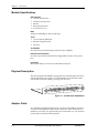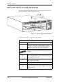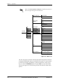
1
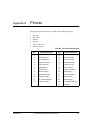
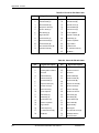
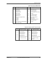
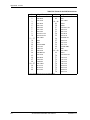
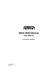
ATLAS Quad USSI Module
USER MANUAL
Part Number 1200261L1
61200261L1-1A
April 1999
901 Explorer Boulevard
P.O. Box 140000
Huntsville, AL 35814-4000
(256) 963-8000
© 1999 ADTRAN, Inc.
All Rights Reserved.
Printed in U.S.A.
ADTRAN Year 2000 (Y2K) Readiness Disclosure
ADTRAN has established a Year 2000 program to ensure that our products will correctly function in
the new millennium. ADTRAN warrants that all products meet Year 2000 specifications regardless of
model or revision. Information about ADTRAN's Year 2000 compliance program is available at the following:
Product Matrix
www.adtran.com/y2kfax.html
E-mail
[email protected]
Faxback Document
Line
(256) 963-8200
Y2K plans and product certifications are listed in the Product Matrix (see
above).
Y2K Project Line
(256) 963-2200
iii
Federal Communications Commission Radio Frequency Interference Statement
This equipment has been tested and found to comply with the limits for a Class A digital device, pursuant to Part 15 of the FCC Rules. These limits are designed to provide reasonable protection against
harmful interference when the equipment is operated in a commercial environment. This equipment
generates, uses, and can radiate radio frequency energy and, if not installed and used in accordance
with the instruction manual, may cause harmful interference to radio frequencies. Operation of this
equipment in a residential area is likely to cause harmful interference in which case the user will be required to correct the interference at his own expense.
Shielded cables must be used with this unit to ensure compliance with Class A FCC limits.
Change or modifications to this unit not expressly approved by the party responsible for
compliance could void the user’s authority to operate the equipment.
Warranty and Customer Service
ADTRAN will replace or repair this product within five years from the date of shipment if the product
does not meet its published specification, or if it fails while in service. For detailed warranty, repair, and
return information, refer to the ADTRAN Equipment Warranty and Repair and Return Policy Procedure (see the last page of this manual).
A return material authorization (RMA) is required prior to returning equipment to ADTRAN.
For service, RMA requests, or more information, see the last page of this manual for the toll-free contact
number.
International CISPR 22 (EN55022) Class A Products
The following information must be included in the user manuals of all Class A (commercial) equipment
sold in Europe:
This is a Class A product. In a domestic environment, this product may cause radio interference, in which case the user may be required to take adequate measures.
iv
Table of Contents
List of Figures ..........................................................................................................................vii
List of Tables ............................................................................................................................ ix
Chapter 1.
Introduction ............................................................................................................................. 1-1
ATLAS Quad USSI Module overview .......................................................................................................... 1-1
Features ...................................................................................................................................................... 1-1
Interfaces ................................................................................................................................................... 1-1
Module Specifications .............................................................................................................................. 1-2
Physical Description ................................................................................................................................. 1-2
Adapter Cable ........................................................................................................................................... 1-2
Chapter 2.
Installation ............................................................................................................................... 2-1
Unpack and Inspect ......................................................................................................................................... 2-1
Contents of ADTRAN Shipment ............................................................................................................ 2-1
Wiring ................................................................................................................................................................ 2-1
Installing the ATLAS Quad USSI Module ................................................................................................... 2-2
Chapter 3.
Operation.................................................................................................................................. 3-1
Overview ........................................................................................................................................................... 3-1
Password Security Levels ............................................................................................................................... 3-1
TERMINAL Menu Structure .......................................................................................................................... 3-1
Menu Descriptions ........................................................................................................................................... 3-3
> Slt .................................................................................................................................................................... 3-3
> Type ................................................................................................................................................................ 3-3
> Menu ............................................................................................................................................................... 3-4
> Alarms ............................................................................................................................................................ 3-4
> Test .................................................................................................................................................................. 3-4
> State ................................................................................................................................................................ 3-4
> Status .............................................................................................................................................................. 3-4
> Rev .................................................................................................................................................................. 3-4
ATLAS Quad USSI Module Menu Options ................................................................................................. 3-5
> Quad USSI Info ............................................................................................................................................. 3-5
» Part Number............................................................................................................................................... 3-5
» Serial Number ............................................................................................................................................ 3-5
> Quad USSI Alarms ....................................................................................................................................... 3-5
» SLIP.............................................................................................................................................................. 3-5
» PLL ............................................................................................................................................................... 3-5
» ZERO ........................................................................................................................................................... 3-5
» NO EXT CLK .............................................................................................................................................. 3-5
> DTE Status ..................................................................................................................................................... 3-6
> Data Rate ........................................................................................................................................................ 3-6
61200261L1-1
ATLAS Quad USSI Module User Manual
v
Table of Contents
> Inband STATS ............................................................................................................................................... 3-6
> PLL/FIFO ....................................................................................................................................................... 3-6
> Configuration ................................................................................................................................................ 3-7
» Name............................................................................................................................................................ 3-7
» Clk (+/-) ...................................................................................................................................................... 3-7
» Data .............................................................................................................................................................. 3-7
» CTS ............................................................................................................................................................... 3-7
» DCD ............................................................................................................................................................. 3-7
» DSR............................................................................................................................................................... 3-7
» DTR .............................................................................................................................................................. 3-7
» 0 Inh ............................................................................................................................................................. 3-7
» Inband.......................................................................................................................................................... 3-7
» Send Leads .................................................................................................................................................. 3-7
> Test .................................................................................................................................................................. 3-8
» Loopbk......................................................................................................................................................... 3-8
» Loopback Status ......................................................................................................................................... 3-9
» 511 ................................................................................................................................................................ 3-9
» 511 Result .................................................................................................................................................... 3-9
» Inject............................................................................................................................................................. 3-9
» 511 Clr.......................................................................................................................................................... 3-9
> DTE Interface ................................................................................................................................................. 3-9
» DTE Interface Mode................................................................................................................................... 3-9
» Current DTE Type ..................................................................................................................................... 3-9
Appendix A. Dial Plan Interface Configuration ..................................................................................... A-1
Appendix B. Pinouts .................................................................................................................................... B-1
Index .................................................................................................................................Index-1
vi
ATLAS Quad USSI Module User Manual
61200261L1-1
List of Figures
Figure 1-1.
Figure 2-1.
Figure 3-1.
Figure 3-2.
Figure 3-3.
Figure A-1.
61200261L1
ATLAS Quad USSI Module . . . . . . . . . . . . . . . . . . . . . . . . . . . . . . . . . . . . . . . . . . . . . . . . . . . 1-2
Installing the Quad USSI Module . . . . . . . . . . . . . . . . . . . . . . . . . . . . . . . . . . . . . . . . . . . . . . 2-2
Menu Tree . . . . . . . . . . . . . . . . . . . . . . . . . . . . . . . . . . . . . . . . . . . . . . . . . . . . . . . . . . . . . . . . . . 3-2
Modules Menu . . . . . . . . . . . . . . . . . . . . . . . . . . . . . . . . . . . . . . . . . . . . . . . . . . . . . . . . . . . . . . 3-3
Quad USSI Module Menu Options . . . . . . . . . . . . . . . . . . . . . . . . . . . . . . . . . . . . . . . . . . . . . 3-5
Dial Plan Menus . . . . . . . . . . . . . . . . . . . . . . . . . . . . . . . . . . . . . . . . . . . . . . . . . . . . . . . . . . . . . A-1
ATLAS Quad USSI Module User Manual
vii
List of Figures
viii
ATLAS Quad USSI Module User Manual
61200261L1
List of Tables
Table 3-1.
Table B-1.
Table B-2.
Table B-3.
Table B-4.
Table B-5.
Table B-6.
Normal Mode Operation............................................................................................................ 3-8
Pinout for EIA-530 Cable............................................................................................................B-1
Pinout for EIA-530A Cable ........................................................................................................B-2
Pinout for RS-449 Cable..............................................................................................................B-2
Pinout for RS-232 Cable..............................................................................................................B-3
Pinout for CCITT X.21 (V.11) Cable..........................................................................................B-3
Pinout for the DB-78 Connector ................................................................................................B-4
61200261L1-1
ATLAS Quad USSI Module User Manual
ix
List of Tables
x
ATLAS Quad USSI Module User Manual
61200261L1-1
Chapter 1
Introduction
ATLAS QUAD USSI MODULE OVERVIEW
The ATLAS Quad USSI Module provides four synchronous DTE ports, each
of which can operate at any rate that is a multiple of 56 or 64 kbps, up to
2.048 Mbps. You can install the ATLAS Quad USSI Module into any available option slot of the ATLAS_800 chassis.
Features
•
•
•
•
•
•
•
Each port operates using 1 to 32 time slots, each time slot being 56 or 64
kbps
Includes an elastic store for absorption of rate variations
Any port can be used as a timing source for the entire system
Outputs a 50 percent duty-cycle output clock at all rates
Generates and responds to V.54 looping codes
Generates and checks 511 test patterns
Bidirectional loopbacks:
- Port (toward the network)
- DTE (toward the DTE)
You can invoke loopbacks locally or remotely (V.54).
Interfaces
•
•
•
•
•
•
61200261L1-1
EIA-530
EIA-530A
RS-449
RS-232
CCITT X.21 (V.11)
Connector: DB-78
(DB-78 to Dual D sub connector adapter cables ship with this module.)
ATLAS Quad USSI Module User Manual
1-1
Chapter 1. Introduction
Module Specifications
DTE Interface
• EIA-530 Synchronous
• EIA-530A Synchronous
• RS-449
• RS-232 Synchronous
• CCITT X.21 (V.11)
Rate
56 kbps to 2.048 Mbps in 56K or 64K steps
Tests
• Local Loopback (Bilateral)
• Remote Loopback (V.54)
• Self Test
Test Pattern
511 with errored seconds display and error inject capability
Excessive 0s Protection
Excessive zeros alarm indication and configurable excessive zeros protection
Connector
DB-78 with cables to convert to D sub female connectors
Physical Description
The ATLAS Quad USSI Module can plug into any available option slot in the
ATLAS_800 chassis (see Figure 1-1). The module has an indication under
each D-shell connector referring to the port on the card.
PORT 1&2
USSI
PORT 3&4
Figure 1-1. ATLAS Quad USSI Module
Adapter Cable
Two ADTRAN-supplied adapter cables convert from the DB-78 connectors
on the rear of the module to Dual D sub connectors. These connectors are
marked as 1/3 and 2/4 to represent the port connected (1 or 3/2 or 4), based
on the cable to which the DB-78 attaches.
1-2
ATLAS Quad USSI Module User Manual
61200261L1-1
Chapter 2
Installation
UNPACK AND INSPECT
Carefully inspect the option module for any shipping damage. If damage is
suspected, file a claim immediately with the carrier and then contact
ADTRAN Technical Support. (See the last page of this manual for
information on contacting Technical Support.) If possible, keep the original
shipping container for returning the option module to ADTRAN for repair
or for verification of damage during shipment.
Contents of ADTRAN Shipment
•
•
•
The ATLAS Quad USSI Module
The ATLAS Quad USSI Module User Manual (to be inserted into the appropriate section of the ATLAS_800 User Manual)
Two DB-78 to dual D sub adapter cables
Customers must provide the DTE cables.
WIRING
Each of the ATLAS Quad USSI Module ports contains a D sub connection
(via the supplied adapter cables). Appendix B contains the pinouts for the
various cables.
61200261L1-1
ATLAS Quad USSI Module User Manual
2-1
Chapter 2. Installation
INSTALLING THE ATLAS QUAD USSI MODULE
Figure 2-1 represents the action required to properly position the ATLAS
Quad USSI Module within the ATLAS chassis.
PORT 1&2
USSI
PORT 3&4
Figure 2-1. Installing the Quad USSI Module
Follow the steps below to install the option module:
Instructions for Installing the ATLAS Quad USSI Module
Step
Action
1
Remove the cover plate (corresponding to the option slot
into which you want to install the ATLAS Quad USSI
Module) from the ATLAS 800 chassis rear panel.
Dangerous voltage is exposed when the cover plate is
removed.
2-2
2
Slide the ATLAS Quad USSI Module into the ATLAS 800
chassis until the module is positioned firmly against the
front of the ATLAS Base Unit.
3
Using a screwdriver, tighten the thumbscrews at both
edges of the option module.
4
Connect the cables to the associated device(s).
5
Complete installation of remaining modules and Base
Unit as specified in the Installation chapter of the ATLAS
800 User Manual.
ATLAS Quad USSI Module User Manual
61200261L1-1
Chapter 3
Operation
OVERVIEW
You can configure and control the ATLAS Quad USSI Module from a variety
of sources, including the following:
•
•
The ATLAS Front Panel provides minimal configuration and status support.
The terminal menu allows detailed configuration, status, and diagnostics.
You can access the terminal menu from either a VT-100 terminal attached to
the ATLAS Base Unit’s control port, or through a Telnet session established
through the Base Unit’s Ethernet port. ATLAS User Manual provides detailed
instructions on operating each of the supported management approaches.
This chapter describes the menu items presented when managing
the ATLAS Quad USSI Module via the terminal menus.
PASSWORD SECURITY LEVELS
To edit items in the terminal menu, you must have the appropriate password level. Each menu description in this section indicates the required
password level required for write and read access. ATLAS security levels
range from level 5 (most restrictive) through level 0 (most permissive). See
the section Access Passwords in the ATLAS 800 User Manual for detailed information on working with passwords.
TERMINAL MENU STRUCTURE
The ATLAS 800 uses hierarchical menus to access all of its features. The topmost menu level leads to submenus which are grouped by functionality (see
Figure 3-1). All menu items display in the terminal window.
61200261L1-1
ATLAS Quad USSI Module User Manual
3-1
Chapter 3. Operation
Refer to the ATLAS 800 User Manual for detailed instructions on
how to navigate through the terminal menu.
Quad USSI Info
Part Number
Serial Number
SLIP
Quad USSI
Alarms
PLL
ZERO
NO EXT CLK
Modules
Slt
Type
Menu
Alarms
Test
State
Status
Rev
DTE Status
Data Rate
Inband Stats
PLL / Fifo
Configuration
Test
DTE Interface
Name
Clk (+/–)
Data
CTS
DCD
DSR
DTR
0 Inh
Inband
Send Leads
Loopbk
Loopback Status
511
511 Result
Inject
511 Clr
DTE Interface Mode
Current DTE Type
Figure 3-1. Menu Tree
The ATLAS System Controller automatically detects the presence of the ATLAS Quad USSI Module when it is installed in the system. To see the menus
for the ATLAS Quad USSI Module via the terminal menu, use the arrow
keys to scroll to the Modules menu and press Enter to access the module
choices (see Figure 3-2). The following sections describe all of these menu
options.
3-2
ATLAS Quad USSI Module User Manual
61200261L1-1
Chapter 3. Operation
Figure 3-2. Modules Menu
MENU DESCRIPTIONS
To help you follow the terminal menu hierarchy, the following notations are used.
> MAIN MENUS
»
Submenus
»» Sub-submenus
>
SLT
Read security: 5
Displays the number of available slots in the ATLAS chassis. Slot 0 refers to
the ATLAS Base Unit. This field is read-only.
>
TYPE
Write security: 3; Read security: 5
Displays the type of module actually installed in the slot or the type of
module you plan to install in the slot. If an ATLAS Quad USSI Module is
installed, the Type field automatically defaults to USSI (the ATLAS Quad
USSI Module). You can use this field to preconfigure a system before actually installing modules by simply specifying the module that you want to
install in each slot.
If you install a module in a slot, then want to install a different type
of module in the slot, you must set this field to Empty before
selecting another module type.
If a module is installed, Type automatically displays the name of
the installed module, and cannot be set to any other option.
61200261L1-1
ATLAS Quad USSI Module User Manual
3-3
Chapter 3. Operation
>
MENU
Displays additional status and configuration menus for the selected module.
(To access the menus options for this item, use the arrow keys to scroll to the
Menu column for the module you want to edit, and press Enter.) For detailed
information on each menu option, see ATLAS Quad USSI Module Menu Options on page 3-5.
>
ALARMS
Read security: 5
Displays whether there is an alarm condition on the ATLAS Quad USSI
Module. Press Enter in this field to activate the Alarm menu.
>
TEST
Read security: 5
Displays whether the ATLAS Quad USSI Module is executing a test. Press
Enter in this field to activate the Test menu.
>
STATE
Write security: 3; Read security: 5
Allows an installed module to be marked Offline, which may be useful in
system troubleshooting. Although a module is physically installed, it must
be marked Online for it to be considered an available resource.
>
STATUS
Read security: 5
This is a read-only field presenting status information on the ATLAS Quad
USSI Module. The following messages may display:
Online
The module is enabled, and is responding to the System
Controller’s status polls. This is the normal response of the
system.
No Response
The module is enabled, but is not responding to the System
Controller’s status polls. This response indicates either a
problem in the system or that the module is not installed.
Empty
The System Controller has not detected the presence of a
module in the slot, nor has a module been manually enabled for this option slot.
Offline
The module is installed, but has been taken Offline by a user. The module is still responding to controller polls.
Offline/
No Response
The module is installed, but has been taken Offline by a user. The module is not responding to polls.
Not Supported The module is not supported by the current ATLAS Base
Unit.
>
REV
3-4
Read security: 5
(Hardware Revision) Displays the hardware revision of the ATLAS Quad
USSI Module. This is a read-only field.
ATLAS Quad USSI Module User Manual
61200261L1-1
Chapter 3. Operation
ATLAS QUAD USSI MODULE MENU OPTIONS
Figure 3-3 shows the menu options available for the ATLAS Quad USSI
Module. The following sections describe these options.
Figure 3-3. Quad USSI Module Menu Options
>
QUAD USSI INFO
Read security: 5
Indicates the module status. These fields are read-only.
» Part Number
Displays the module part number.
» Serial Number
Displays the module serial number.
>
QUAD USSI
ALARMS
Read security: 5
Displays any active alarms. These fields are read-only.
» SLIP
A rate mismatch exists between the DTE clock and the network-side clock
(as set by DS0 assignment).
» PLL
The USSI port cannot lock onto the clock provided by the network interface.
» ZERO
The DTE is sending an excessive number of consecutive zeroes to the network interface.
» NO EXT CLK
The DTE is not providing an external transmit clock (if the USSI port is configured to get transmit clock from the DTE).
61200261L1-1
ATLAS Quad USSI Module User Manual
3-5
Chapter 3. Operation
>
DTE STATUS
Read security: 5
Shows the status of the following key DTE interface signals (read-only).
RTS
Request To Send from DTE
CTS
Clear To Send to DTE
DTR
Data Terminal Ready from DTE
DSR
Data Set Ready to DTE
DCD
Data Carrier Detect to DTE
RI
Ring Indicate to DTE
TD
Transmit Data from the DTE
RD
Receive Data toward the DTE
EC
External Clock from the DTE
>
DATA RATE
Read security: 5
Displays the data rate at which each USSI port currently operates. The
number of DS0s assigned to a port and the rate per DS0 associated with the
active maps determines a port’s data rate.
>
INBAND
STATS
Read security: 5
Displays information useful when using the inband control channel capability of the USSI.
>
PLL/FIFO
3-6
Rx Frames
Number of frames received on inband control channel
Tx Frames
Number of frames sent on inband control channel
Rx Bytes
Number of bytes received on inband control channel
Tx Bytes
Number of bytes sent on inband control channel
Reset Stats
Resets all above fields to zero
Read security: 5
Indicates status of circuitry used to generate and detect data clock and the
status of elastic store buffer.
Lock
Phase Lock Loop is locked
RXE
Receive data FIFO Empty
RXF
Receive Data FIFO Full
TXE
Transmit Data FIFO Empty
TXF
Transmit Data FIFO Full
ATLAS Quad USSI Module User Manual
61200261L1-1
Chapter 3. Operation
>
CONFIGURATION
Configures the ATLAS Quad USSI Module.
» Name
Write security: 3; Read security: 5
Allows you to enter a descriptive alpha-numeric name for each port.
» Clk (+/-)
Write security: 3; Read security: 5
(TX Clock Polarity) Controls the clock used by the ATLAS Quad USSI Module to accept the transmit (TX) data from the DTE. This is usually set to Normal. If the interface cable is long, causing a phase shift in the data, the clock
can be set to Inverted. This setting switches the phase of the clock, which
should compensate for a long cable.
» Data
Write security: 3; Read security: 5
(Data Format) Inverts DTE data. This inversion can be useful when operating with a high-level data link control (HDLC) protocol (often used as a
means to ensure 1s density). Select either Normal or Inverted.
» CTS
Write security: 3; Read security: 5
(Clear to Send) Controls characteristics of CTS (see Table 3-1). Choose from
Normal or Forced On.
» DCD
Write security: 3; Read security: 5
(Data Carrier Detect) Indicates to the DTE when a valid signal is being
received at the Network Interface (see Table 3-1). Choose from Normal or
Forced On.
» DSR
Write security: 3; Read security: 5
(Data Set Ready) Indicates to the DTE when the DCE is turned On and
ready for operation (see Table 3-1). Choose from Normal or Forced On.
» DTR
Write security: 3; Read security: 5
(Data Terminal Ready) Determines whether the ATLAS_800 treats a connection as permanent (DTR=Ignore) or temporary, connecting only when DTR
is active, (DTR=Connect On DTR). Select either Ignore or Connect on
DTR.
» 0 Inh
Write security: 3; Read security: 5
(Zero Inhibit) Instructs the ATLAS 800 to send 1s toward the network when
the port detects an uninterrupted string of 0s transmitted for more than one
second.
» Inband
Write security: 3; Read security: 5
Creates an 8 kbps management channel by robbing a bit from the first DS0
assigned to the port. This channel can manage remote ADTRAN products.
» Send Leads
Write security: 3; Read security: 5
Sends the state of the DTE leads to the remote unit whenever any DTE lead
changes state. See the online help menus for more information.
61200261L1-1
ATLAS Quad USSI Module User Manual
3-7
Chapter 3. Operation
Table 3-1. Normal Mode Operation
Conditions Causing Port Control Signal Deactivation
Signal
CTS
DCD
DSR
RTS
Follows
—
—
V.54 Loopback
Off
—
Off
511 Test On
Off
—
Off
Self-test Active
Off
Off
Off
Network Test Active
Off
—
Off
No DS0 Mapped
Off
Off
Off
Network Alarm
Off
Off
—
— = Do not care
>
TEST
Activates specific data ports testing. It also controls the activation of loopbacks and the initiation of data test patterns. Test results display on the
ATLAS_800 front panel.
Executing port tests disrupts normal data flow in the test port.
» Loopbk
Write security: 4; Read security: 5
Controls the activation and deactivation of loopbacks.
No Loopback
The loop is deactivated.
Local Loopback
The USSI port activates both a local loopback (back toward the DTE) and a port loopback when invoked.
Remote Loopback The remote loopback causes a V.54 loopback code to be
sent to the far end. If the device at the far end supports
V.54, the device activates a loopback on detection of the
V.54 code.
3-8
ATLAS Quad USSI Module User Manual
61200261L1-1
Chapter 3. Operation
» Loopback Status
Read security: 5
Indicates a port’s current loopback status by displaying any of the following status messages (read-only):
No loopback active
Looping up remote unit
Remote unit looped back
Looping down remote unit
Remote loopup failed
Port looped from remote source
Port loopback active
» 511
» 511 Result
Write security: 4; Read security: 5
(511 Test Pattern) Controls the activation of the 511 test pattern generator
and detector.
Off
Turns off the 511 test pattern generator and detector.
On
Turns on the 511 test pattern generator and detector.
Read security: 5
Displays the results of the 511 test in the form of the number of errored seconds (read-only).
Sync
Y (yes), N (no)
ES
Errored seconds. Indicates the number of seconds (after pattern
sync) that have contained at least one error.
» Inject
Write security: 4; Read security: 5
(Inject Error) Injects a 511 pattern error.
» 511 Clr
Write security: 4; Read security: 5
(Clear Results) Clears test results for the selected port.
>
DTE INTERFACE
Provides control and information about the DTE interface.
» DTE Interface
Mode
Write security: 3; Read security: 5
Controls the type of electrical DTE interface for the selected port. The Auto
setting works with special ADTRAN cables to automatically detect the type
of interface.
» Current DTE Type
Read security: 5
Displays the current electrical DTE interface type for the selected port.
61200261L1-1
ATLAS Quad USSI Module User Manual
3-9
Chapter 3. Operation
3-10
ATLAS Quad USSI Module User Manual
61200261L1-1
Appendix A
Dial Plan Interface Configuration
Re
pl
ac
e
The User Term option for the Dial Plan menu sets the configuration parameters for the end point for the ATLAS Quad USSI Module. The Dial Plan
menus are only accessible when using terminal mode. To access these
options, select Dial Plan from the top-level menu (see Figure A-1).
Figure A-1. Dial Plan Menus
Interface Configuration
This section describes the Dial Plan / User Term configuration settings for
the ATLAS Quad USSI Module.
The USSI can only serve as a User Termination end point.
> USER TERM
When working in the User Term section of the Dial Plan and Slt (Slot) is
defined as a USSI module, the following configuration options are available:
» Ports Available
Indicates which of the four ports of the ATLAS Quad USSI Module have
already been defined either in another switched end point (indicated by
“s”) or in a Dedicated Map (indicated by “n”). This field is read-only.
61200261L1-1
ATLAS Quad USSI Module User Manual
A-1
Appendix A. Dial Plan Interface Configuration
» Number of Ports
Defines to ATLAS how many of the ports could be used to answer calls to
the number(s) defined in the Accept Call list. You can enter numbers 1
through 4. The ports are contiguous beginning with the port number
selected and the number of ports.
Example
If the port selected (as a part of Slot/Port selection) is 2, and the number of
ports selected here was 2, then ports 2 and 3 would be enabled to receive
calls to the numbers listed under the Incoming Call Accept list.
A-2
ATLAS Quad USSI Module User Manual
61200261L1-1
Appendix B
Pinouts
This appendix contains the pinout tables for the following wiring:
•
EIA-530
•
EIA-530A
•
RS-449
•
RS-232
•
CCITT x.21 (V.11)
•
DB-78 connector
Table B-1. Pinout for EIA-530 Cable
Pin
Signal Description
Pin
Signal Description
1
Shield (Ground)
13
Clear to Send (B)
2
Transmit Data (A)
14
Transmit Data (B)
3
Received Data (A)
15
Transmit Clock (A)
4
Request to Send (A)
16
Received Data (B)
5
Clear to Send (A)
17
Receive Clock (A)
6
DCE Ready (A)
18
Local LoopBack*
7
Signal Ground
19
Request to Send (B)
8
Carrier Detect (A)
20
DTE Ready (A)
9
Received Clock (B)
21
Remote Loopback*
10
Carrier Detect (B)
22
DCE Ready (B)
11
Ext. Transmit Clock (B)
23
DTE Ready (B)
12
Transmit Clock (B)
24
Ext. Transmit Clock (A)
25
Test Mode*
* Ignored by Quad USSI Module
61200261L1-1
ATLAS Quad USSI Module User Manual
B-1
Appendix B. Pinouts
Table B-2. Pinout for EIA-530A Cable
Pin
Signal Description
Pin
Signal Description
1
Shield (Ground)
13
Clear to Send (B)
2
Transmit Data (A)
14
Transmit Data (B)
3
Received Data (A)
15
Transmit Clock (A)
4
Request to Send (A)
16
Received Data (B)
5
Clear to Send (A)
17
Receive Clock (A)
6
DCE Ready (A)
18
Local LoopBack*
7
Signal Ground
19
Request to Send (B)
8
Carrier Detect (A)
20
DTE Ready (A)
9
Received Clock (B)
21
Remote Loopback*
10
Carrier Detect (B)
22
Ring Indicator
11
Ext. Transmit Clock (B)
23
Signal Ground
12
Transmit Clock (B)
24
Ext. Transmit Clock (A)
25
Test Mode *
* Ignored by Quad USSI Module
Table B-3. Pinout for RS-449 Cable
Pin
Signal Description
Pin
Signal Description
1
Shield (Ground)
19
Signal Ground
2
Signaling Rate Indicator*
20
Receive Common*
3
Not Used
21
Not Used
4
Transmit Data (A)
22
Transmit Data (B)
5
Transmit Clock (A)
23
Transmit Clock (B)
6
Received Data (A)
24
Receive Data (B)
7
Request to Send (A)
25
Request to Send (B)
8
Receive Clock (A)
26
Receive Clock (B)
9
Clear to Send (A)
27
Clear to Send (B)
10
Local Loopback*
28
Terminal in Service*
11
DCE Ready (A)
29
DCE Ready (B)
12
DTE Ready (A)
30
DTE Ready (B)
13
Carrier Detect (A)
31
Carrier Detect (B)
14
Remote Loopback*
32
Select Standby*
15
Ring Indicator
33
Signal Quality*
16
Select Frequency*
34
New Signal*
17
Ext. Transmit Clock (A)
35
Ext. Transmit Clock (B)
18
Test Mode*
36
Standby/Indicator*
37
Send Common*
* Ignored by Quad USSI Module
B-2
ATLAS Quad USSI Module User Manual
61200261L1-1
Appendix B. Pinouts
Table B-4. Pinout for RS-232 Cable
Pin
Signal Description
Pin
Signal Description
1
Shield (Ground)
14
Sec. Transmit Data
2
Transmit Data
15
DCE Transmit Clock
3
Received Data
16
Sec. Received Data
4
Request to Send
17
Receive Signal Element Timing
5
Clear to Send
18
Not used
6
Data Set Ready
19
Sec. Request to Send
7
Signal Ground
20
Data Terminal Ready
8
Received Line Signal Detector
21
Signal Quality Detector *
9
+ Voltage *
22
Ring Indicator
10
- Voltage *
23
Data Signal Rate Selector *
11
Not used
24
DTE Transmit Clock
12
Sec. Received LIne Signal Indicator
25
Not used
13
Sec. Clear to Send
* Ignored by the Quad USSI Module
Table B-5. Pinout for CCITT X.21 (V.11) Cable
Pin
61200261L1-1
Signal Description
Pin
Signal Description
1
Shield (Ground)
8
Signal Ground
2
Transmit Data (A)
9
Transmit Data (B)
3
Request to Send (A)
10
Request to Send (B)
4
Received Data (A)
11
Received Data (B)
5
Carrier Detect (A)
12
Carrier Detect (B)
6
Transmit/Receive Clock (A)
13
Transmit/Received Clock (B)
7
Ext. Transmit Clock (A)
14
Ext. Transmit Clock (B)
15
Not Used
ATLAS Quad USSI Module User Manual
B-3
Appendix B. Pinouts
Table B-6. Pinout for the DB-78 Connector
Pin
1
2
3
4
5
6
7
8
9
10
11—17
18
19
20
21
22
23
24
25
26
27
28
29—37
38
39
40
Signal Description
RXD-A 2/4
RXD-B 2/4
RXC-A 2/4
RXC-B 2/4
TXD-A 2/4
TXD-B 2/4
TXC-A 2/4
TXC-B 2/4
EXT-TXC-A 2/4
EXT-TXC-B 2/4
NOT USED
GND
GND
CHASIS GND
CTS-A 2/4
CST-B 2/4
DSR-A 2/4
DSR-B/RI 2/4
DCD-A 2/4
DCD-B 2/4
DTR-A 2/4
DTR-B 2/4
NOT USED
RTS-A 1/3
RTS-B 1/3
RTS-A 2/4
Pin
41
42
43—48
49
50
51
52
53
54
55
56
57
58
59
60
61
62—68
69
70
71
72
73
74
75
76
77
78
Signal Description
RTS-B 2/4
GND
NOT USED
MOD2
MOD0
EXT-TXC-A 1/3
DTR-B 1/3
DTR-A 1/3
DCD-B 1/3
DCD-A 1/3
DSR-B/RI 1/3
DSR-A 1/3
CTS-B 1/3
CTS-A 1/3
CHASIS GND
GND
NOT USED
MOD1
EXT-TXC-B 1/3
TXC-B 1/3
TXC-A 1/3
TXD-B 1/3
TXD-A 1/3
RXC-B 1/3
RXC-A 1/3
RXD-B 1/3
RXD-A 1/3
* 1/3 or 2/4 indicates the port on the USSI Module
B-4
ATLAS Quad USSI Module User Manual
61200261L1-1
Index
Numerics
DTR 3-6
0 Inh (zero inhibit) menu 3-7
F
A
FCC statement iv
features 1-1
alarms
NO EXT CLK 3-5
PLL 3-5
SLIP 3-5
Zero 3-5
alarms menu 3-4
ATLAS front panel 3-1
H
hardware revision 3-4
I
C
changing modules 3-3
clock polarity, TX 3-7
configuration menu 3-7
(CTS) clear to send 3-7
0 Inh (zero inhibit) 3-7
data 3-7
DCD (data carrier detect) 3-7
DSR (data set ready) 3-7
DTR (data termnal ready) 3-7
inband 3-7
name 3-7
send leads 3-7
TX clock polarity 3-7
controlling the module 3-1
CTS 3-6
customer service iv
D
data rate 3-6
DCD 3-6
dial plan
interface configuration A-1
number of ports A-2
ports available A-1
user term A-1
DSR 3-6
DTE signal status 3-6
DTE status 3-6
61200261L1-1
inband menu 3-7
inband statistics 3-6
info menu 3-5
inject error 3-9
installing the module 2-2
installing the Quad USSI 2-1
interface configuration A-1
interfaces 1-1
L
local loopback 3-8
loopback
local 3-8
none 3-8
remote 3-8
loopback status 3-9
loopback test 3-8
M
menu
description 3-3
options 3-5
Quad Nx 56/64 3-5
structure 3-1
submenu items 3-5
menu descriptions
ATLAS 3-3
alarms 3-4
menu 3-4
rev menu (hardware revision) 3-4
ATLAS Quad USSI Module User Manual
Index-1
Index
slt (slot) 3-3
state 3-4
status 3-4
test 3-4
type 3-3
Quad USSI 3-5
alarms
NO EXT CLK 3-5
PLL 3-5
SLIP 3-5
Zero 3-5
alarms menu 3-5
configuration 3-7
0 Inh 3-7
Clk (+/-) 3-7
CTS 3-7
data 3-7
DCD 3-7
DSR 3-7
DTR 3-7
inband 3-7
name 3-7
send leads 3-7
data rate 3-6
DTE status 3-6
inband stats 3-6
info 3-5
part number 3-5
PLL/FIFO 3-6
serial number 3-5
test 3-8
511 3-9
511 Result 3-9
clear results 3-9
inject 3-9
loopback status 3-9
loopbkt 3-8
module detection 3-2
N
NO EXT CLK alarm 3-5
no loopback 3-8
number of port, dial plan A-2
O
offline 3-4
online 3-4
operating the module 3-1
operation 3-1
operation, overview 3-1
P
part number 3-5
Index-2
password 3-1
password security level 3-1
pattern generator and detector test 3-9
PLL alarm 3-5
PLL/FIFO 3-6
ports available, dial plan A-1
Q
Quad Nx 56/64
features 1-1
installing 2-2
menu options 3-5
Quad USSI
adapter cable 1-2
controlling 3-1
features 1-1
installation 2-1
interfaces 1-1
operation 3-1
overview 1-1
physical description 1-2
specifications 1-2
wiring 2-1
R
RD 3-6
remote loopback 3-8
rev menu 3-4
RI 3-6
RTS 3-6
S
self test 3-8
send leads menu 3-7
serial number 3-5
SLIP alarm 3-5
slot 0 3-3
slot menu 3-3
state menu 3-4
status menu 3-4
status messages 3-4
T
TD 3-6
Telnet session 3-1
terminal menu 3-1
test menu 3-4, 3-8
511 3-9
511 Result 3-9
clear results 3-9
inject 3-9
loopback status 3-9
ATLAS Quad USSI Module User Manual
61200261L1-1
Index
wiring for the Quad USSI 2-1
loopbk 3-8
type menu 3-3
Y
V
VT-100 terminal emulation 3-1
Y2K iii
year 2000 compliancy iii
W
Z
warranty and customer service iv
Zero alarm 3-5
61200261L1-1
ATLAS Quad USSI Module User Manual
Index-3
Index
Index-4
ATLAS Quad USSI Module User Manual
61200261L1-1
Product Support Information
Presales Inquiries and Applications Support
Please contact your local distributor, ADTRAN Applications Engineering, or ADTRAN Sales:
Applications Engineering
(800) 615-1176
Sales
(800) 827-0807
Post-Sale Support
Please contact your ADTRAN account representative first. If your ADTRAN account representative cannot
help, please contact ADTRAN Technical Support and have the unit serial number available.
Technical Support
(888) 4ADTRAN
Repair and Return
If ADTRAN Technical Support determines that a repair is needed, Technical Support will coordinate with
the Customer and Product Service (CAPS) department to issue an RMA number. For information regarding
equipment currently in house or possible fees associated with repair, contact CAPS directly at the following
number:
CAPS Department
(256) 963-8722
Identify the RMA number clearly on the package (below the mailing address), and return to the following
address:
ADTRAN Customer and Product Service
6767 Old Madison Pike
Progress Center
Building #6 Suite 690
Huntsville, Alabama 35807
RMA # _____________