1
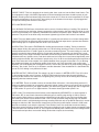
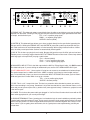
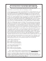
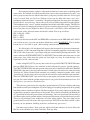
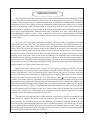
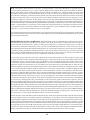
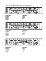
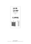
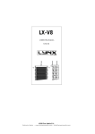
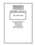
OWNER'S MANUAL
LANGEVIN
DUAL VOCAL COMBO
MANLEY
LABORATORIES, INC.
MANUFACTURED BY:
MANLEY LABORATORIES, INC.
13880 MAGNOLIA AVE.
CHINO, CA. 91710 USA
TEL: (909) 627-4256
FAX: (909) 628-2482
email:[email protected]
http://www.manleylabs.com
REV. 5-01-01; "P" SUFFIX
CONTENTS
SECTION
PAGE
INTRODUCTION
3
FRONT PANEL
4, 5
BACK PANEL
6
MIC PRE BASICS
7
CONNECTING YOUR PREAMPLIFIER
8, 9
OPERATION NOTES
10, 11
SPECIFICATIONS
12
TROUBLESHOOTING
13, 14
INTERNAL ADJUSTMENTS
15
INTERNAL LAYOUT
16
REPLACING FUSES
17
MAINS CONNECTIONS
18
WARRANTY
19
WARRANTY REGISTRATION
20
APPENDIX A: WIRING YOUR OWN CABLES
21
APPENDIX B: TEMPLATE FOR STORING SETTINGS
22
INTRODUCTION
THANK YOU!...
for choosing the Langevin Dual Vocal Combo. Manley Labs bought all the rights to the Langevin
name and circuits in 1992. Manley uses the Langevin name for its solid state products including
versions of an all discrete Pultec and Electro-Optical Limiter, and Mic Preamp.
The Dual Vocal Combo is the result of a suggestion to combine the "Langevin Dual Mono
Microphone Preamplifier with EQ" with the "Langevin Dual-Channel Electro-Optical Limiter" for
a competitively priced stereo or 2 channel VoxBox-like product. Both the mic preamp and the
Langevin EL-OP are recognised as great values and serious high performance all-discrete professional
units. While the combination is not quite a "solid state VoxBox" because it doesn't have some of the
compressor & EQ functions and no de-esser, it is 2 channels of the "essentials" for half the price.
The "Combo" is 100% discrete transistor in the signal path and there are no op-amps except to drive
the LEDs in the Opto circuit, and the Meter circuit. Negative feedback is minimal, only one
transformer (mic input) per channel and much of the components are the same as in the Manley tube
gear. While we were planning this unit we upgraded the front panel Instrument Inputs for higher input
impedance (150K ohms) and higher gain (25 dB more) so virtually all guitars, bassers and synths and
drum machines could be recorded direct-to-tape comfortably.
Thank you again, and please enjoy!
WATER & MOISTURE
As with any electrical equipment, this equipment should not be used near water or moisture. If liquid
enters the preamplifier, it must be immediately returned to your dealer for servicing.
SERVICING
The user should not attempt to service this unit beyond that described in the owner's manual. Refer
all servicing to Manley Laboratories.
WARNING!
!
TO PREVENT THE RISK OF ELECTRIC SHOCK
DO NOT OPEN THE CABINET
REFER SERVICING TO
QUALIFIED PERSONEL
3
A
INPUT
B
C
80 Hz
D
L.F.
E
EQ IN
F
H.F.
G H
I H G
POWER
12 KHz
OFF ON
PHANTOM
by Manley Laboratories Inc.
40 Hz
DIRECT
INPUT
IN
-10
-1
+10
GAIN
GAI
EQ OUT
-10
-1
REDUCTIO
REDUCTION
+10
8 KHz
E
80 Hz
L.F.
D
C
EQ IN
H.F.
B
A
12 KHz
INPUT
8 KHz
ATTENUATE
ATTENUAT
PHANTOM
(PULLON)
ATTENUATE
ATTENUAT
F
(PULLON)
DUAL VOCAL COMBO
METER
OUTPUT
40 Hz
-10
-1
METER
OUTPUT
SEP
+10
EQ OUT
REDUCTION
REDUCTIO
-10
-1
+10
GAI
GAIN
IN
DIRECT
INPUT
LINK
LIMITER
REDUCTION
REDUCTIO
BYPASS
J
K
L
M
N
REDUCTION
O
P
0
N
BYPASS
M
L
K
J
The Dual Vocal Combo has 2 channels which are mirror images of each other and is further divided into top
and bottom sections which correspond to the Mic Pre with EQ and the Opto-Limiter Sections. Don't let the
mirror image aspect confuse you!
A) INPUT ATTENUATE. This is the basic GAIN control which can also be considered MIC GAIN or INPUT
LEVEL. The range is from "off" to 50 dB of gain. Don't be afraid of turning this knob as loud as is needed. It is
the first component (other than the mic transformer) in the signal path so exceptionally loud signals can be
attenuated enough to prevent clipping in almost all situations.
B) 80 Hz / 40 Hz. Sets the corner frequency for the L.F (Low Frequency) Shelf EQ. Mostly frequencies below
the setting get affected but the gentle slope means that some frequencies higher than the corner also get
boosted or cut.
C) L.F. How much boost or cut is applied to the lows. The range is from -10 dB to +10 dB. It is intended as a
safe, smooth basic tone control and not as a comprehensive 'do everything' EQ but is very effective at
compensating for the proximity effect from Cardioid pattern mics.
D) EQ IN / EQ OUT. EQ OUT Bypasses the EQ stage and EQ IN allows boosting and cutting.
E) H.F. How much boost or cut is applied to the highs. The range is from -10 dB to +10 dB. Also intended as
a safe, smooth basic tone control and very effective for adding that 'air' or 'sparkle' when needed.
F) 12kHz / 8 kHz. Sets the corner frequency for the H.F (Low Frequency) Shelf EQ. Mostly frequencies above
these points get boosted or cut but some effect is still heard below these points. Watch out for sibilance
problems.
G) PHANTOM POWER. Puts 48 volts on the mic XLR connector to power certain mics. The LEDS (H) next to
the switches will glow when PHANTOM power is ON. THIS SWITCH MUST BE PULLED TO TOGGLE.This
is to prevent accidents like blowing your speakers. ALWAYS turn down the INPUT ATTENUATE before
hitting this switch. Mic signals are typically one hundredth of a volt and phantom is 48 volts so expect it to
POP unless the INPUT is turned down. The big POP can also happen if you change a mic, mic cable, mic
patch, etc. Turning down the monitors, headphone levels, etc is the alternative but get into the habit of turning
it down with mics even when you aren't using Phantom. Also note that if you have slightly intermittant or dirty
connectors in the mic path, that noises will be far worse.
Phantom power is only required for solid state condensor mics and not dynamic mics, tube mics and
especially not for old ribbon mics. Some vintage ribbon mics can be damaged with Phantom. FET condensor
mics will generally be silent without phantom. With most mics, phantom power will have no effect, not make
them sound worse, unless there are dirty connectors.
I) POWER ON / OFF. When power is turned ON the VU Meters will glow. If not, then make sure the power
cable is plugged in or the fuse has not blown.
4
J) DIRECT INPUT. This is for plugging in an electric guitar, bass, synth, etc into the Dual Vocal Combo. The
input impedance is high (150 kOhms) appropriate for these instruments and there should be plenty of gain
available. Electric guitars and basses may need a fair amount of H.F. Boost to sound comparable to an amp
because there happens to be a lot of H.F. boost going on in the innards of most amps. A jack plugged into
this input will interrupt the normal mic XLR input.
OPTO-LIMITER SECTIONS
K) IN / BYPASS. BYPASS turns off the limiter and its controls. IN allows limiting or levelling. This should be
the most used control on the limiter. Always compare the original sound to the sound after the limiter to verify
you are not accidentally over-squashing. Remember that sound is compised of pitch, duration and volume or
dynamics. The point is not to throw away one element (dynamics) just tame it and control it as needed.
L) GAIN. This is the 'Make-up Gain' after the limiter. It is usually set so that there is no volume change when
switching IN / BYPASS to allow easy A/B comparisons OR as the final output level to optimise how hard the
signal is hitting tape or to optimise the level to an A to D convertor.
M) REDUCTION. This sets the THRESHOLD of limiting and the amount of limiting. Turning it clockwise,
creates deeper limiting. We generally advise that 4 to 6 dB of limiting (levelling) is fine for vocals and most
individual intruments and 1 to 3 dB is good for percussive sounds and mixes. Too much limiting on a mix will
usually first make the drums quieter which is not generally desirable. The amount one should 'level' vocals
depends mostly on the singer's technique and talent, the musical style and the thickness of the arrangement.
Sometimes with very dynamic vocals, loud dense tracks and a mix that is not vocal forward significantly more
levelling might be needed. We have heard of people using 10 to 12 dB of vocal limiting with good results but a
bunch more extra care will be needed. In the pauses between lines, the gain will rise that 10 or 12 dB along
with headphone leakage, air conditioning rumble, throat noises, etc. Don't forget that if you are like many
engineers, you will be limiting the vocal again in the mix, so don't feel you have to do all the limiting during the
recording - play it safe. There is no Un-Do button, and the alternative is the dreaded Re-Do. Questionble EQ,
you can fix, over limiting is very difficult to fix later.
N) METER OUTPUT / REDUCTION. This switch is for the VU meters. In METER OUTPUT, the VU's show
the final output level like most VU meters. In REDUCTION mode the meters show how much limiting is
occurring in dBs. Because VU meters are not lightning-fast, you may not see all the limiting that is actually
happening with fast transient sounds.
O) VU METERS. These are smaller versions of standard Sifam VU meters. It is worth pointing out that VU
meters were always intended to correspond to apparent 'volume' similar to how our ears work and are not like
the 'peak' meters you have on your digital recorders. VU meters work great for analog tape, but for digital use
the 'LED ladders' on your A to D or digital machine. The meters should glow when power is on.
P) SEP / LINK. This switch allows the 2 limiters to act independently (SEPARATE) or to 'track' together in
LINK mode. SEP is used if each channel has different types of sounds going through it. LINK is used for
stereo sounds. When limiters or compressors are linked and a loud signal on one side forces limiting then,
both limiters pull down the same amount of dBs. This is so that the center image doesn't tug one direction
then the other, which is a bit distracting and wrong sounding. With this unit, set up BOTH channels for normal
limiting then switch to LINK. Some limiter compressors just use the just left channel controls in LINK mode
and while convenient is not really the right way. Those limiters "mono" the audio that controls the limiting
which gives excess limiting for sounds in the center and no limiting for out-of phase sounds, meanwhile peaks
in either channel can overload the A to D. The Langevin and Manley units combine the control voltages rather
than the audio and provide a more useful limiting function but not quite as conveniently.
5
MIC IN
BALANCED
LINE OUT
PREAMP OUT
OUT
UNBALANCED
ONLY
OUT
UNBALANCED
ONLY
AN EVEANNA MANLEY PRODUCTION
MANLEY LABORATORIES
13880 MAGNOLIA AVE., CHINO, CA 91710
PHONE (909) 627-4256 FAX (909) 628-2482
email: [email protected]
A
MIC IN
PREAMP OUT
N9512423
POWER
CIRCUIT
REPLACE FUSE
WITH SAME
TYPE AND
RATING
LIMITER IN
BALANCED
LINE OUT
GROUND
LIMITER IN
CHASSIS
B
CAUTION - RISK OF ELECTRIC
SHOCK. DO NOT OPEN.
REFER SERVICING TO QUALIFIED
PERSONNEL ONLY
CHANNEL 2
SERIAL NUMBER
CHANNEL 1
TO REDUCE THE RISK OF ELECTRIC
SHOCK DO NOT EXPOSE THIS
EQUIPMENT TO RAIN OR MOISTURE
C
D
E
F
G
H
E
D
C
A) PREAMP OUT. This balanced output comes directly from the mike pre and allows you to use the mike pre
separate from the limiter. Inserting a TRS plug into this jack breaks the normal signal path between the mike
pre output and the limiter input.
TIP= +, hot or positive going signal
RING= -, or negative going signal
SLEEVE= Ground (shield)
B) LIMITER IN. This balanced input allows you to insert a signal directly into the opto-limiter, bypassing the
mike pre and EQ. Utilizing the PREAMP OUT and LIMITER IN jacks with a patch bay allows the mike pre
and limiter sections to be used independently or linked externally. With no plugs inserted in either of these
jacks, the mike pre and opto-limiter sections are automatically linked together.
C) MIC IN. This is where you plug in the mic cable. Because this input has up to 50 dB of gain and can have
Phantom power, we strongly suggest that the INPUT ATTENUATE and/or monitor level is turned way down to
avoid huge pops or thumps when you plug a cable in here.
Pin 1 = Ground (shield)
Pin 2 = +, hot or positive going signal
Pin 3 = -, low or negative going signal
D) BALANCED LINE OUT. This is the final output after the Mic Pre, EQ and Opto-Limiter. It is ONLY meant to
drive balanced inputs. If you are driving an unbalanced input, use the OUT UNBALANCED ONLY jack.
E) OUT UNBALANCED ONLY. Use a regular 1/4" plug here to connect to an unbalanced or balanced input.
The nominal output here is +4dBm and not the -10dBu "consumer" level found on some budget semi-pro
gear. To feed that kind of input, you have to turn down the INPUT ATTENUATOR or better yet, the Limiter's
GAIN and ignore the VU meter which is set up for +4 levels.
TIP = +, hot or positive going signal
SLEEVE = Ground (shield)
F) FUSE. This is a 1/4" 1 amp slo-blo fuse. The fuse is a protection device intended to protect you and the
unit in case something is very wrong. Sometimes it is just the fuse that fails for some unknown reason, so if it
blows and you can't power up the unit, try another fuse (same type and value). If it blows too, prepare to send
in the unit for repair.
G) POWER. This is where the power cable gets plugged in. You Dual Vocal Combo should come with an IEC
power cable appropriate for your country and voltage.
H) GROUND TERMINALS. These 'ground posts' are intended to help in some installations particularly where
a special audio grounding scheme is used. The top post is the audio circuit ground and the bottom is chassis
and AC third pin ground. For almost all applications these posts are connected together with a strap or solid
piece of wire. If you are getting hums and buzzes, this is a good place to start experimenting, and why we
include them.
6
MIC PRE BASICS
This Microphone Preamp, like most mic preamps, is pretty easy to use. First we can discuss why
outboard mic pre's have become "a must have item" in almost every studio even though your console
probably has a bunch of them and that manufacturer claims that they are really great and you don't need
outboard mic pre's. Then, why is everybody buying them, using them, and why are most people going back
to tubes or vintage transistor based circuits?
Good question. The signal from a typical mic is very low - anywhere from 20 to 70 dB below your
normal line level signals. 95% of the time 30 to 40 dB of gain is all that is needed to boost the signal to line
levels. Where you really need a lot of gain is with most ribbon mics and when you are recording chamber
music from a distance. Mic signals are fragile and raw. The fragility is apparent when one compares various
mic pre's - each preamp seems to sound different - no EQ, no compression, nothing elaborate - just basic
gain. Maybe it is the mic reacting different into different circuits. Each preamp, tube or solid state seems
to impart a flavour or color (or personality) of its own. Some of these flavours are subtle and some are not.
A few engineers have an array of mic pre's and use them almost like effects - using each for a certain flavor
as needed. The rest of us only have the budget for one or two great mic pre's so we tend to choose one that
sounds "best", or is priced for us, or is used by "xxxxxx". The Langevin Microphone Preamplifier is superb
sounding - probably because it has a simple all discrete gain stage with a minimum of components and a
minumum amount of negative feedback. Specifications, while important, will not be truly indicative of an
audio product's "sound" until methods of determining the transient accuracy are established. Transient
accuracy is not a "spec" and test benches don't produce hit records. The transient details are important for
reproducing the true character of the instrument, the room and stereo image. Most solid state circuits use
a large amont of negative feedback to lower noise and distortion at the cost of transient accuracy. This
preamplifier started out clean and quiet so minimal negative feedback was necessary.
Op-amp based designs, by comparison, have dozens of transistors in each "chip" (its easier to
fabricate a transistor than a resistor on silicon), hundreds of dB's of negative feedback and sometimes a few
discrete transistors to provide performance that an "IC" simply cannot. The result is good specs - but that
harsh, hard, cold sound that makes shakers sound like pink noise, makes vocals sibilant in an unpleasant
way, and can only render a 2 dimensional image at best. We prefer tubes or simple discrete circuits.
We mentioned mic signals are fragile and raw. Some consider that the "headroom" factor is the most
important issue in mic pre's. We believe that it is just one of a number of issues including the harmonic
character of the distortion. Except for the final output, all circuits are "Class A" which is usually associated
with zerocrossover distortion and near clipping will be even order distortion and less upper harmonics.This
Preamplifier has more headroom than most solid state mic pre's because of the 48 volt power supply used,
compared to 30 volts (+/- 15V or 24 volts) used in other designs. If overdriven, which is not easy, it starts
to clip in a gentle, smooth way.
Another consideration above and beyond technical concerns when it comes to the art of
recording music is that every preamp seems to have some comparative influence on the
"sound" of the mic signal. When we have a choice, we tend to use the preamp that either best
flatters the singer or instrument or gets closest to the desired final sonic goal. Sometimes, the
choice is the clean & pristene pre and sometimes it is the vintage or aggressive box but it
seems to be getting rarer that we choose the basic console mic preamps. The Dual Vocal
Combo is typically considered "clean but vintage" and not as "dry" as many all-discrete mic
preamps. People have used the words "smooth" and "strong" to describe it but undoubtedly
you will find your own words to descibe it compared to your console and other units.
7
CONNECTING YOUR PREAMPLIFIER
Easy - Connect the mic to the Microphone Input XLR, then connect the Line Output to your
tape machine or console. Read on, there are some things to consider.
On the back panel are female XLR's labelled MIC INPUT A and MIC INPUT B. The signal
from the MICROPHONES get plugged in here. Here are a few warnings and suggestions.
These XLR connectors also "send" PHANTOM POWER to the mics. Some mics can be
damaged by the 48 volts of phantom power. A few PZMs and a few ribbon mics have been
known to "fry" when fed phantom power. The suggestion is to ALWAYS have PHANTOM
switched off when switching mics, cables, patches that involve mics etc. You ONLY use
phantom power for PRO SOLID STATE "FET' CONDENSOR MICS. Tube mics, dynamic
mics, ribbon mics and battery powered mics should have phantom switched "off". This is
true for all mic pre's. With this MIC PRE you "PULL THE TOGGLE to SWITCH PHANTOM". It is a locking toggle to prevent "accidents". The second great reason for not using
phantom if you don't have to is that - if you change a connection (patching) with phantom
on, then the pre amp will be fed a quick burst of 48 volts (when it normally is amplifying
about a hundredth of a volt), which can then be monitored - usually once. After you have
replaced your speakers, you have learned a valuable lesson about turning down the volume of
the monitors before changing mics or mic patches. This is a good idea with phantom on or
off. Consider a variation of this - any mic connection just a little bit bad,will be extra noisy
with phantom turned on. This goes for cables, patchbays, patch cords etc. Suggestion #2 Avoid running mic signals through patchbays. Some patchbays "ground" all the "sleeves"
which can add a ground loop into your delicate mic signal. Suggestion #3 - Set up the Mic
Pre in the studio near the mic and use a short mic cable. Why ? Microphones often have
"light duty" line drivers and you can lose an audible amount of signal in long cables. You can
get the best fidelity by having the Mic Pre close to the mic at the "cost" of having to walk
into the studio to adjust a level control. You also avoid almost all of that phantom power /
patching problem because now you are patching a regular line level signal only.
TheMIC INPUT XLR PIN OUT is :
PIN 1 = CIRCUIT GROUND
PIN 2 = HOT or positive going phase
PIN 3 = LOW or negative going phase
The LINE OUTPUT XLR PIN OUT is:
PIN 1 = CIRCUIT GROUND
PIN 2 = HOT or positive going phase
PIN 3 = LOW or negative going phase
This is a simple balanced output. It will feed balanced inputs but not unbalanced inputs
"correctly". When it is plugged into an unbalanced input, expect a 6 dB loss of output level.
Use the 1/4" unbalanced output to drive unbalanced inputs. The best way to drive an
unbalanced input with the balanced XLR is not to connect to PIN 3 at the output XLR - just
use PIN 1 (ground) and PIN 2 (signal). Better to have PIN 3's signal float than short which
will distort quietly and you may not notice the 6 dB loss.
8
Reversing the polarity or phase is often needed when two or more mics are picking up the
same source. For example it would be needed when one mics the top and bottom of a snare - one
skin is going towards one mic and the other skin is going away from the other mic. If one signal
is not "reversed" then you lose lows. Polarity reverse can also help with some vocal / mic /
headphone situations because " somewhere " the polarity flipped one too many times. It happens.
General advise - try it each way - listen, with vocals, always ask the singer which way they prefer.
The headphones may "cancel" with the sound they hear in their skull while singing. This Mic Pre
has no provision for changing the polarity. If you are recording direct to tape it is a good idea to
have a few phase reverse adapters on hand. All you need is two XLRs (a male and female) and
a foot of mic cable. It doesn't matter which end is which. Wire it up as follows:
PIN 1 (Shield) > PIN 1
PIN 2 > PIN 3
PIN 3 > PIN 2
You can use this between the MIC and PREAMP or often between the PREAMP and TAPE. If
you use both at once, you come out in phase. Mark these cables PHASE REV ! This is another
reason why a 1 foot cable is good - thus avoiding confusion with normal cables.
We did include a 1/4 inch phone jack input on the front panel for electronic instruments.
This input has a 150k ohm input impedance similar to instument amplifiers which range from
50K to 1M ohm. It provides a good input with gain control and EQ limiting and meters. You
can use either the INSTRUMENT INPUT or MIC INPUT but not both at the same time. As with
guitar amps, long cables from the guitar can lose highs so it may be worth having a low
capacitance 10 foot cable on hand.
On the wiring PIN-OUTS, you may have noticed we specified CIRCUIT GROUND rather
than just GROUND. We have a few terminals on the back panel for various "ground schemes".
The CIRCUIT GROUND is the same ground as the electronics in the Mic Pre while the CHASSIS
GROUND is the same as the steel enclosure that is bolted to the rack and is also connected to the
"third pin AC Mains Ground. Both terminals are normally connected together with a small
"ground strap" but this strap can be moved to the side and wire can be attached to the terminals.
These are "MINI BANANA" style and will not accept regular size bananas found on electronic
test gear. Be careful with the ground strap because it can get lost if the terminals are loose. If it
does get lost - you can use a short bare wire.
There are two good reasons for using these ground terminals. The first is finding and fixing
hum and the second is preventing hum. If you have plugged everything in right and you are getting
hum then you have a number of options with these terminals. You can try simply moving the strap
so that chassis ground is separate from circuit ground. This is similar to breaking off the third pin
AC ground but includes the ground from rack mounting . One can experiment with attaching a
wire between the console ground and the circuit ground or between a rack and the chassis ground.
These are all techniques some technicians use when wiring studios. They also often cut the
ground (shield) on one side of the cable to prevent loops. DO NOT cut the shield on MIC cables
because you lose phantom, shielding at the mic, and hum only gets worse !
One other cause of hum - Some gear may radiate a field into whatever is closest. Move the
Mic Pre or the offender away from each other. That may help.
9
OPERATION NOTES
The Langevin Electo-Optical Limiter follows certain traits and traditions established by the UREI
LA-3A and similar levelling amplifiers. These traits can be divided into two aspects - electronic and
operation. The electronic concept is simple and rather clean. Use the audio to light up LEDs which shine
onto photo-resistors. These photo-resistors in combination with a fixed resistor simply act as a voltage
divider to attenuate the signal. The line amplifier only functions to provide extra gain to make up for
attenuation losses and then act as a fine cable driver. Simple, elegant and minimal. Operation aspects are
also simple, elegant and minimal. There are usually only a "threshold" and "gain" control. Most have no
user adjustment of "attack", "release", "ratio" or functions for de-essing or external sidechains. The user
is "stuck" with fixed time constants and a feature list that seems anemic compared to dynamic processors
costing far less.
So why are "LA" style opto based limiters so popular ? Several reasons. To paraphrase Letterman
"The number one reason why "LA" style limiters are favorites is because.... they work right on vocals".
This "rightness" has a few aspects. The first is that "LA" style limiters don't leave much trace of limiting
as they work. This is partly due to tubes, partly to the simplicity of the opto circuit and partly because
the user can't alter the attack and release. Almost every VCA based design seems to leave electronic
personality on that critical vocal track. This is usually undesirable. Our Opto circuits has no active
limiting in the signal path. Tube circuits have the potential to be musically more transparent than
transistors because tubes are generally more linear devices. However, there are many poor examples of
tube circuits in use, and many ways to butcher the quality. We chose to use our Langevin line amplifier
circuit which we also use in the Langevin Enhanced Pultec Equalizers (rather than copy UREI designs)
because frankly our circuit sounds better and cleaner.
Back to this matter with fixed time constants. We get requests to modify our "ELOP" for more
controls but we get even more people raving about how great and useful the "ELOP" is now. The attack,
release, knee and ratio (curve) are a function of the Vactrol Cell we chose to use. The choice was based
on the attack and release characteristics. Changing the time values in this circuit involves different
choices of Vactrols. Not practical. Not in a "LA" style limiter. There is a major advantage to fewer
controls. You simply adjust the Threshold for the desired limiting amount and adjust the Gain for the
desired level to tape - then record. The limiter does what its supposed to do - nothing more - nothing less.
Kinda like automatically right, strangely quick and easy, and pretty much non-distracting. We use the
phrase "Set it and forget it". This is a very important feature that would be lost with a variety of controls.
A good engineer wants to be ready to record "now" and does not want to be fussing with controls while
a lead vocal is going to tape. Unfortunately most compressors drag the engineer's attention away (and
often the singer's and producer's attention away as well).
The time and slope characteristics of Opto elements are not easy to describe and probably even
more difficult to simulate. The attack is fast, not super fast "brick wall", but fast enough to "catch"
consonants. It is also a function of level. At lower reduction levels and lower peaks the Vactrol is slower.
It becomes faster with sharp peaks and heavier levels of reduction. Release is similar but 10 to 20 times
slower. Quick peaks are handled with quick release and as gain reduction nears zero the Vactrol gets
slower like gentle braking to a stop. It is possible to"trick out" an opto circuit for conventional operation
but generally the results have been not well liked.
10
The slope or ratio is also difficult to simulate. The initial ratio is low and becomes higher with
more gain reduction until the leds light up fully and further reduction is not easy. This upper limit of
reduction is in the area of 20 dB or at the bottom of the GR meter where the ratio becomes low again
but this would be a severe setting that few engineers could use. Distortion becomes audible at very
deep limiting. In a tech shop, it is easy to drive the limiter to 20 dB of reduction and beyond where the
GR meter shows a flaw in that it "folds back". We put a higher priority on having the meter show
what the Opto was doing accurately with "normal settings" than extreme test bench observations. Test
benches don't make hit records.
So the Opto Limiters seem to be great for vocals, what else are they used for and what about
sounds where the time constants are less than optimum ? Historically "LA" style limiters are often
used for bass and guitar tracks. They can be ideal for brass, saxes, synths and similar sounds with
superb results. There are other compressors that work well for these instruments but few that are as
transparent. Usually, when you hear of an engineer using a non-Opto compressor for these
instruments it is usually framed with "for the crunch" or because they add some desired color. There
is only a very small number of "clean" general purpose variable time compressors which seem to give
Opto units competition - our Variable MU is at the top of that list. Where the "LA" style limiters are
not always appropriate is for percussion and for mixes where the percussion is just right. The Opto
typically reacts fast to peaks - fast enough to remove drums from a mix but not quite fast enough to be
called "brick wall". Individual drums tend to have a little of the initial transient let through but the
desirable tone of the drum is diminished. If used gently, this can be applied to brighten up the attack
of the drum, but it is difficult to apply in practice because drums can be very dynamic. One great use
is on the room mics. The initial drum sound is pulled down, then the natural reverb is increased.
Shades of early Led Zep. While we mentioned that "LA" style limiters are not what we suggest for
mixes, there are times when the drums are too loud or when the engineer can mix "into" the limiter.
Both techniques are possible but not necessarily easy. One trick is very little movement on the GR
meter. Some of our clients use the Opto on mixes as an effect. This application is valid as long as the
effect given and the effect desired are the same. There is not many options for adjustment and fine
tuning. The good news is that at least the Manley is clean enough to pass a good mix. In a live sound
setting the Opto will perform as a fine speaker protection device. Once again the Threshold is set for
minimal limiting with music and is just adjusted to occasionally pull down peaks. Ideally you won't
be able to hear a little limiting like this. You can easily get about 3 dB of limiting on a mix before it
becomes audible in most situations. If the limiter GR meters are typically hitting -6 on a mix then the
limiting will probably be obvious and most styles of music will suffer somewhat.
If what you want is to use a box to process a mix or drums, then you should probably be using a very
good compressor that has attack, release and a low ratio. "Multiband Compressors" are OK for this,
but in most peoples hands they have become something to be feared especially by mastering
engineers who can rarely fix the damage done. It has become common for people to be sent back to
the studio to re-mix, minus the multi-band. The only mastering engineers we know that own them
keep them in the closet except to demonstrate why not to use them and show the comparison between
a pro mastering processing chain and cheese.
11
SPECIFICATIONS
Frequency Response
20 Hz to 20 KHz (+/- 1 dB) Mic Pre
20 Hz to 50 KHz (+/- .5 dB) Limiter
THD & Noise
.075%
.06%
Signal to Noise ratio
107 dB
Limiter
Headroom
26 dB (ref +4 dBv)
Limiter
Maximum Output
+30 dBv (75 volts p to p)
Limiter
Maximum Input (with Input at max)
70 mV mic,
Maximum Gain (factory set for 45 dB)
38 dB to 53 dB (internal trimmer) Mic
25 dB Direct Instrument 1/4" input
(knob set to 45 dB)(off to +40 dB range)
15 dB
Limiter
Maximum Limitting
20 dB
Attack Time (fixed)
Release Time (fixed)
20 mS
500 mS
Input Impedance
(1Khz @ +4 dBm) Mic Pre
(1Khz @ +4 dBm) Limiter
800mV direct
11 dB w +4 sine
2400 Ohm, transformer coupled
(optimised for mics with 100 to 600 ohm output impedances)
150,000 Ohm @ 1/4" direct input
Output Impedance
11 Ohms (balanced)
6 Ohms (unbalanced)
XLR Pin-Out (balanced)
PIN 1 = Ground or Shield
(not appropriate for driving unbalanced inputs)PIN 2 = HOT (+)
PIN 3 = LOW (-)
1/4" Phone Jack Pin-Out (unbalanced)
Sleeve = Ground or Shield
Tip = Signal
(We suggest mono plugs but if a stereo plug must be used the Ring needs to be connected
to the Sleeve)
Power Consumption
Size
Shipping Weight
20 watts
19" X 3.5" X 10" (1U)
20 lbs
12
TROUBLE-SHOOTING
There are a number of possible symptoms of something not quite right, some may be interfacing, others we will touch
on as well. The Dual Vocal Combo has a variety of balanced and unbalanced inputs and outputs optimised for typical standards
and most problems are due to the right cable in the wrong jack. However if you suspect a problem the following paragraphs
should help.
NO POWER, NO INDICATORS, NADA - Probably something to do with AC power. Is it plugged in? Check the fuse on
the back panel. A blown fuse often looks blackened inside or the little wire inside looks broken. A very blackened fuse is a big
hint that a short occured. Try replacing the fuse with a good one of the same value and size. If it blows too then prepare to send
the unit back to the dealer or factory for repair. The fuse is a protection device and it should blow if there is a problem. If the
unit works with a new fuse, fine. Check the MAINS VOLTAGE SELECTOR if one is fitted. Some of our models are able to
have them and some don't. It should be set correctly for your mains voltage.
LIGHTS BUT NO SOUND - First try plugging the in and out cables into some other piece of gear to verify that your wires
are OK. Assuming that it was OK into the other unit it probably is still a wiring thing. The AES standard calls PIN 2 HOT on
XLRs but there is still lots of gear out there with PIN 3 HOT. When two units are connected and both are unbalanced but don't
seem to agree which pin is hot - the signal is shorted out. If it is not lost entirely, it will be almost gone and extremely distorted.
THE CURE - a phase reversing adapter that swaps pin 2 and pin 3 on one XLR - or get out a soldering iron and swap wires
yourself. All Manley gear after 1995 is pin 2 hot. Some Manley gear has balanced and floating outputs and some has unbalanced
transformerless outputs. This unit has two discrete line drivers - one driven from the other. If the XLR pin 2 is shorted to ground
or pin 3 there will be no signal from the XLR. If pin 3 is shorted to ground - a typical way to drive unbalanced inputs - then
the output on pin 2 will be 6 dB low. The best way to drive unbalanced inputs is with the unbalanced outputs.
LEVELS SEEM TO BE WRONG, NO BOTTOM - Several possible scenarios.
The above paragraph describes the output line drivers. If you are using the balanced XLR outputs and feeding an unbalanced
input (it happens) you will only be getting 1/2 the signal which means that you lost 6 dB. There is a "trick" if you just want to
use the XLRs but from time to time feed unbalanced inputs. Insert a 1/4" mono (tip - sleeve) plug (unwired) into the unbalanced
output. This makes the levels right. You could leave this plug in permanently but we don't recommend it because you can have
6 dB more headroom into balanced inputs if it is removed. More headroom is one of the biggest factors of great sounding gear.
Manley uses the professional standard of +4 dBm = Zero VU = 1.23 volts AC RMS. A lot of semi-pro gear uses the hi-fi
reference of -10 dBm = Zero VU. This is a 14 dB difference that will certainly look goofy and may tend to distort. Often there
are switches on the semi-pro gear to choose the pro reference level. We do not provide that kind of switch because of inevitable
compromises in the signal path. If the loss looks close to 6 dB and it sounds thin then one half of the signal is lost. The cause
is probably wiring again. One of the two signal carrying wires (the third is ground / shield on pin 1) is not happening. Check
the cables carefully because occasionally a cable gets modified to work with a certain unit and it seems to work but its wrong
in other situations. If only one side of the Limiter exhibits this problem, it may be a problem in the Limiter. See the next item.
If you have almost no signal and what you can hear is distorted then you probably have pin 2 shorted to ground or to pin 3.
This might happen if the cable is mis-wired and/or you are feeding an unbalanced input.
USING THE 1/4" JACKS BUT THE LEVEL IS LOW - The 1/4" output jacks on this unit are unbalanced and require a
mono plug (tip - sleeve plug) and not a stereo plug (tip - ring - sleeve plug. The Limiter uses the ring to set the output level for
this output. When the ring is shorted to the sleeve the output becomes 6 dB louder. This is needed because the XLR has
differential outputs which together give that extra 6 dB. Using the ring compensates for this difference and both outputs will
be the same level (+4 dBv). Other manufactures often use a common circuit that does this in a different automatic way. The
generic name is "transformer like" but unlike transformers, these outputs can be unstable (oscillates) into some cables and often
have low headroom into unbalanced inputs. Our method works better as long as one uses a mono phone plug.
We have included an appendix: WIRING YOUR OWN CABLES that may help.
For reference both the XLR and 1/4" back panel inputs are balanced electronically and not with a transformer. The inputs will
work fine and should reject hum from either balanced or unbalanced outputs. The 1/4" Direct input on the front is unbalanced
and meant for guitars and basses. In many situations it can be used for low level sources but watch out for ground loop related
hum.
13
HUM - Let's assume it knows the words. Once again - several possibilities - several cures. Most likely it is a ground loop. The
two most common procedures are: try a 3 pin to 2 pin AC adapter (about a dollar at the hardware store) which is better than
messing up the power cable by bending the ground pin until it breaks off. Method two - cutting the shield on one side of the
cable. This is usually done at every female XLR to "break" all loops. You may get a loop simply from the rack. All the other
gear in the rack is "dumping" ground noise onto the rack rails. Try removing the Limiter from the rack so that it is not touching
any metal. You may have cured a non-loop hum. Some gear radiates a magnetic field and some gear (especially if it has
transformers) might receive that hum. A little distance was all it took. This unit has GROUND terminals on the back panel.
Normally these terminals are simply connected together with a "ground strap" (a small flat piece of metal that can become lost).
First check that the strap is connecting the two ground terminals. If missing try a short piece of wire to connect these terminals.
Not that - try separating them, try connecting a wire from the rack to the each terminal, try connecting a wire from the console
to the terminals (one at a time). These terminals are meant to help with a variety of different studio "grounding schemes".
Experiment - you will come up with the best way for your situation.
A cool method of reducing all sorts of hum and noise is to use the new 60-0-60 balanced AC power transformers available from
Equi=Tech and Furman. It costs more but works best. Hum might be because of the unbalanced input but this hints at ground
loops and questionable wiring.
THE METERS ARE OUT OF CALIBRATION - If the problem only seems to be when the unit is just turned on it's normal.
It should warm up. It might be a half dB out for 15 minutes - relax. If they drift a tenth of a dB over the course of a day it is
because of bad AC power fluxuations - chances are other gear is doing worse, you just haven't found out yet. Your unit will
have been factory calibrated and tested twice before you received it. Sometimes parts drift a bit in value over the years, or you
have repaced tubes and want the unit calibrated at the same time, or you just want it as perfect as it can be. These are good reasons
to turn the page and go through the calibration procedure or sent it to a technician or the factory for a tweak. If you send the
unit to a tech, you should include this manual because they will need it. If you do it yourself, you will need an Oscillator and
a few screwdrivers and it would be nice to have a VOM meter and Scope but not necessary.
Once in a while we get a call from a client with a "digital studio" with confusion about levels. They usually start out by using
the digital oscillator from their workstation and finding pegged VU meters the first place they look and they know it can't be
the workstation. Even a -6 level from their system pegs the meters. Some of you know already what 's going on. That -6 level
is referenced to "digital full scale" and the computer might have 18 or 18.5 or 20 dB of headroom built in. That -6 level on the
oscillator is actually a real world analog +12 or +14 and those VU meters don't really go much further than +3. There are a few
standards and plenty of exceptions. One standard is that pro music (non-broadcast) VU meters are calibrated for 0VU = +4 dBm
=1.228 volts into 600 ohms. Another standard is that CDs have a zero analog reference that is -14 dB from digital full scale
or maximum. This allows sufficient peak headroom for mixed material but would be a bad standard for individual tracks
because they would likely distort frequently. This is why digital workstations use higher references like 18 and 20 - to allow
for peaks on individual sounds. It may be too much in some cases and too little in others. Add two other sources of confusion.
Peak meters and VU meters will almost never agree - they are not supposed to. A peak meter is intended to show the maximum
level that can be recorded to a given medium. VU meters were designed to show how loud we will likely hear a sound and help
set record levels to analog tape. By help, I mean that they can be only used as a guide combined with experience. They are
kinda slow. Bright percussion may want to be recorded at - 10 on a VU for analog tape to be clean but a digital recording using
a good peak meter should make the meter read as high as possible without an "over". Here is the second confusion: There aren't
many good peak meters. Almost all DATs have poor peak meters that do not agree with each other. One cannot trust them to
truly indicate peaks or overs. Outboard digital peak meters (with switchable peak hold) that indicate overs as 3 (or 4)consecutive
samples at either Full Scale Digital (FSD) are the best. They won't agree with VU meters or Average meters or BBC Peak meters
either. Each is a different animal for different uses. The Limiter should help digital and analog achieve consistent levels but
use each meter for it's own strength. The Reduction mode is useful with everything.
We hear the phrase "brick wall limiter" bantered about these days. Theoretically this kind of limiter would be ideal just before
an analog to digital converter or broadcast transmitter. Unfortunately, we don't know of one that sounds OK for most mixes
or general purpose applications. This limiter is better than most for this application but it is not a perfect ultra-fast brick wall.
It is fast enough to significantly reduce transients in a mix (kills drums) and has a steep ratio (better than 10:1) after a few dB
of limiting (soft knee). It will allow for several dB louder mixes and/or no percievable A to D distortion. If used for this purpose,
we suggest that one only uses a few dB of gain reduction or else your mix may change. The alternative is to "mix into the limiter"
so that mix decisions are based on hearing how the limiter is reacting. This can be a little dangerous with material that has
changes in dynamics. It works best with automated mixes and awareness that drums may be a moving target.
14
INTERNAL ADJUSTMENTS
(see layout on page 16)
1)
+45 Volt DC adjust with meter from ground to resistor marked by arrow. Check this first and adjust if
needed. It is the power supply regulator adjustment. Now for the audio ....
You will have to start out by setting front panel controls to these settings: BYPASS mode, SEP /
LINK OFF, REDUCTION controls counter clockwise (MIN), GAIN to 1:00 or unity, Balance
at 12:00. The top will need to be open. There are two screws on the top that hold the top perforated
panel in place. Remove these and the top will slide back. Be careful! THERE ARE HIGH
VOLTAGES
INSIDE THE LIMITER. DO NOT HOLD THE METAL PART OF THE SCREWDRIVER. DO NOT
PROBE PROBE AROUND WITH THE SCREWDRIVER OR FINGERS. The unit should be on for
about 15 minutes to allow for "warming up".
2 & 3) This adjusts thelimiter amplifier gain in all modes. 1 KHz sine at 1.23 volts RMS (+4 dBm, 0 VU) to
both inputs. BYPASS mode. Adjust 2 & 3 for unity gain at outputs.
4 & 5) This adjusts VU meter calibration for OUTPUT. Same input, Meter switches to OUTPUT. Adjust for
0 VU on the Meters.
6 & 7) This adjusts the meter zero for Reduction mode. Meter switches to REDUCTION. Adjust for 0 VU on
the Meters.
8 & 9) This adjusts the meter in Reduction mode to reflect the actual gain reduction accurately. You will
probably need to increase the oscillator 10 dB to get Limiting. Switch from BYPASS to IN. Meter
switches to OUTPUT. Adjust GAIN controls to get 0 VU on the METERS again, then adjust
REDUCTION controls to reduce the signal to -4dB. Switch METERS to REDUCTION. Adjust 8 &
9 to get -4 dB on the METERS.
10)
This adjusts the gain of the right side chain and adjusts the side chain balance in Link. Switch the
LINK ON. There should be 1 to 2 dB change in the Meters. Adjust 10 so that the meter is the
same for both sides. You may have to re-adjust 8 and 9. Check that both in LINK and
SEPARATE that both channels show the same reduction.
11)
Sets the gain for each channel's Mic Pre. Use a low level input in the mic XLRs and adjust each
channel for 45 dB of gain with the Input Attenuator wide open fully CW.
12)
Sets the Direct (Instrument) Input gain. Use a low level input in the 1/4" front panel jacks and adjust
each channel for 25 dB of gain with the Input Attenuator wide open fully CW.
15
16
12
6469
MIC INPUT
XFMR
2
11
DIRECT INPUT
GAIN
MICPRE GAIN
GAIN
METER CAL
"OUTPUT"
PRINT AND INSERT IN OWNWERS
MANUAL AS PG. 16
ERASE THIS NOTE FIRST
4
LANGEVIN DUAL VOCAL COMBO
PCB VER. 2001
S/N'S LDVCP
6
8
LINK ADJ.
10
LANGEVIN DUAL VOCAL COMBO
ADJUSTMENT LOCATIONS
METER CALIBRATION
" 0 VU "
METER CALIBRATION
"GAIN REDUCTION"
LM317
HVT P+
7
9
1
154 R
3
5
12
6469
MIC INPUT
XFMR
DIRECT INPUT
GAIN
MICPRE GAIN
11
ELOP GAI
GAIN
METER CAL
"OUTPUT"
45 TO 48 VDC
REGULATOR OUTPUT
VOLTAGE ADJ
REPLACING FUSES
1
2
Phantom Volts Fuse = AGC 4/10A Fast blow
Changing the fuse is easy and can be done without any tools and while the DVC is still in a rack.
1) Disconnect the IEC AC mains for safety
2) Rotate the fuse cap anti-clockwise 1/4 turn
3) Remove the fuse and replace it with a new slow/blow 1/2 AMP, 250 VOLT, MDL type fuse
4) Reconnect the IEC AC mains, turn on the power and meter lamps should once again glow.
If the new fuse also blows, it means there is probably a problem in the Dual Vocal Combo that needs fixing.
Fuses are meant to blow in those situations to protect against further damage including fire and the unpleasant
smell of transformer meltdown. The DVC will need to be sent to the dealer or factory for service.
To change the fuse for the Phantom voltage supply you will need to disconnect the unit from the wall, remove
the top cover off, fuse is located between the two VU meters on the back side. use a fast blow fuse AGC 4/10A
There are no parts that are user servicable. Electrolytic Capacitors should probably be replaced after
10 years in audio gear and some say ICs, transistors and pots should be replaced in 20 years to keep the unit in
optimum condition. This is a general guide for audio gear that is intended to be used for decades. On the other
hand, you can expect to throw away most digital gear after 5 years because in 3 years new stuff does 10 times
more and costs 10 times less. Funny how that stuff ages and fine analog keeps being used for decades. In 1999
64 megs of memory costs about $100 and is 8 chips on 1 module. In 1974 it took 150,000 chips and cost $3
million bucks and now its worth is nothing. Good Analog is a long term thing.
17
MAINS CONNECTIONS
Your unit has been factory set to the correct mains voltage for your country. The voltage setting
is marked on the serial badge, located on the rear panel. Check that this complies with your local
supply. The voltage changeover switch is located inside the unit in the middle of the PCB near the
power transformer. To change the voltage from 120 to 240 volts, simply remove the top cover by
unscrewing the center fixing screw and sliding the top out towards the rear of the chassis. Turn the
top of the voltage changeover switch with a firm positive action using a small flat screwdriver.
Export units for certain markets have a moulded mains plug fitted to comply with local
requirements. If your unit does not have a plug fitted the coloured wires should be connected to
the appropriate plug terminals in accordance with the following code.
GREEN/YELLOW
BLUE
BROWN
EARTH terminal
NEUTRALterminal
LIVE
terminal
As the colours of the wires in the mains lead may not correspond with the coloured marking
identifying the terminals in your plug proceed as follows;
The wire which is coloured GREEN/YELLOW must be connected to the terminal in the plug which
is marked by the letter E or by the safety earth symbol or coloured GREEN or GREEN and
YELLOW.
The wire which is coloured BLUE must be connected to the terminal in the plug which is marked
by the letter N or coloured BLACK.
The wire which is coloured BROWN must be connected to the terminal in the plug which is marked
by the letter L or coloured RED.
DO NOT CONNECT/SWITCH ON THE MAINS SUPPLY UNTIL ALL OTHER CONNECTIONS HAVE BEEN MADE.
18
WARRANTY
All Manley Laboratories equipment is covered by a limited warranty against defects in materials and
workmanship for a period of 90 days from date of purchase to the original purchaser only. A further
optional limited 5 year transferrable warranty is available upon proper registration of ownership within
30 days of date of first purchase.
Proper registration is made by filling out and returning to the factory the warranty card attached to this
general warranty statement, along with a copy of the original sales receipt as proof of the original date
of purchase, or registration can be made online in the Tech Support section of www.manleylabs.com.
This warranty is provided by the dealer where the unit was purchased, and by Manley Laboratories,
Inc. Under the terms of the warranty defective parts will be repaired or replaced without charge,
excepting the cost of tubes. Vacuum tubes and meter or badge lamps are warranted for six months
provided the warranty registration is completed as outlined above.
If a Manley Laboratories product fails to meet the above warranty, then the purchaser's sole remedy
shall be to first obtain a Repair Authorisation from Manley Laboratories and return the product to
Manley Laboratories, where the defect will be repaired without charge for parts and labour. All returns
to the factory must be in the original packing, accompanied by the Repair Authorisation, and must be
shipped to Manley Laboratories via insured freight at the customer's own expense. Factory original
packaging can be ordered from Manley Labs. Customer will be charged for new factory original
packaging if customer fails to ship product to Manley Labs in the original factory packaging. After
repair, the product will then be returned to customer via prepaid, insured freight, method and carrier to
be determined solely by Manley Laboratories. Manley Laboratories will not pay for express or
overnight freight service nor will Manley Laboratories pay for shipments to locations outside the USA.
Charges for unauthorized service and transportation costs are not reimbursable under this warranty,
and all warrantees, express or implied, become null and void where the product has been damaged by
misuse, accident, neglect, modification, tampering or unauthorized alteration by anyone other than
Manley Laboratories.
The warrantor assumes no liability for property damage or any other incidental or consequental
damage whatsoever which may result from failure of this product. Any and all warrantees of
merchantability and fitness implied by law are limited to the duration of the expressed warranty. All
warrantees apply only to Manley Laboratories products purchased and used in the USA. All
warrantees apply only to Manley Laboratories products originally purchased from an authorised
Manley dealer. Warranties for Manley Laboratories products purchased outside the USA will be
covered by the Manley Importer for that specific country or region. "Grey Market" purchases are not
covered by any warranty. In the case that a Manley Laboratories product must be returned to the
factory from outside the USA, customer shall adhere to specific shipping, customs, and commercial
invoicing instructions given with the Return Authorisation as Manley Laboratories will not be
responsible for transportation costs or customs fees related to any importation or re-exportation
charges whatsoever.
Some states do not allow limitations on how long an implied warranty lasts, so the above limitations
may not apply to you. Some states do not allow the exclusion or limitation of incidental or
consequential damages, so the above exclusion may not apply to you. This warranty gives you specific
legal rights and you may also have other rights which vary from state to state.
For Tech Support and Repair Authorisation, please contact:
MANLEY LABORATORIES, INC.
13880 MAGNOLIA AVE.
CHINO, CA. 91710 USA
TEL: (909) 627-4256
FAX: (909) 628-2482
email: [email protected]
19
WARRANTY REGISTRATION
We ask, grovel and beg that you please fill out this registration form and send the bottom half to:
MANLEY LABORATORIES
REGISTRATION DEPARTMENT
13880 MAGNOLIA AVE.
CHINO CA, 91710 USA
Or you may FAX this form in to: +1 (909) 628-2482 or you may fill in the online warranty
registration form found in the Tech Support section of our website www.manleylabs.com or you can
be really diligent and register your warranty three times to see if we get confused!
Registration entitles you to product support, full warranty benefits, and notice of product
enhancements and upgrades, even though it doesn't necessarily mean that you will get them (Just
kidding!) You MUST complete and return the following to validate your warranty and registration.
Thank you again for choosing Manley gear and reading all the way through The Owner's Manual.
(We really mean that sincerely, the bit about thanking you for choosing our gear. THANK YOU!!!)
MODEL _______________ SERIAL #__________________
PURCHASE DATE ______________ SUPPLIER ______________________
-------------------------------------------------------------------------------------------------------PLEASE DETACH THIS PORTION AND SEND IT TO MANLEY LABORATORIES
MODEL _______________ SERIAL #__________________
PURCHASE DATE ______________ SUPPLIER ______________________
NAME OF OWNER _______________________________________________
ADDRESS ______________________________________________________
CITY, STATE, ZIP ________________________________________________
EMAIL: ________________________________________________________
TELEPHONE NUMBER___________________________________________
COMMENTS OR SUGGESTIONS?__________________________________
________________________________________________________________
20
WIRING YOUR OWN CABLES ?
XLR MAL
MALE
VIEWED FROM THE BACK
OR SOLDER SIDE
1/4" MONO PHONE JACK
TIP
XLR MAL
MALE
VIEWED FROM THE SIDE
SLEEVE
SHEL
SHELL
TIP
2
1
SLEEVE
3
1/4" STEREO PHONE JACK
TIP
RING
SLEEVE
RING
TIP
XLR FEMAL
FEMALE
VIEWED FROM THE BACK
OR SOLDER SIDE
XLR MAL
MALE
VIEWED FROM THE SIDE
SLEEVE
SHELL
SHEL
1
1/8" STEREO PHONE JACK
R
T
2
3
S
BANTAM (PATCHBAY) JACK
JACK
RING
TIP
R
T
S
MANLEY GEAR - THIS PAGE CAME WITH GEAR WITH TRUE TRANSFORMER
BALANCED XLR INPUTS AND OUTPUTS. ANY 1/4" JACKS ARE UNBALANCED (NO
TRANSFORMER). TRANSFORMERS PROVIDE THE MOST "FORGIVING & FLEXIBLE"
INTERFACES. OLDER MANLEY GEAR MAY NOT BE BALANCED OR PIN 2 = HOT.
CHECK THE ORIGINAL MANUAL
MANUAL.
LANGEVIN - 1/4" JACKS ARE UNBALANCED AND MUST BE A MONO (T S) PLUG.
SLEEVE
A FEW GENERAL RULES
THE THIN LINES SHOW TWO VARIATIONS DEPENDINDING ON THE WIRE YOU USE
EITHER JOIN PINS 1 & 3 AT THE XLR
OR CONNECT THESE LINES AT THE
PHONE PLUG
1) GROUND = CHASSIS = SHIELD = SLEEVE = PIN 1 on XLRs
XLR
2) THE AES STANDARD FOR XLRs IS:
IS
SHIEL
PIN 1 = SHIELD
PIN 2 = HOT (POS)
PIN 3 = LOW (NEG)
1
FEMALE
FEMAL
BALANCED OR
UNBALANCED
UNBALANCED
3) THE GENERAL CONVENTION FOR 1/4" STEREO, TRS JACKS &
BANTAM JACKS FOR BALANCED SIGNALS IS:
IS
TIP = HOT (POS)
RING = LOW (NEG)
SLEEVE = SHIELD
SHIEL
4) THE GENERAL CONVENTION FOR 1/4" STEREO FOR STEREO
APPLICATIONS (ie; HEADPHONES) IS
IS:
TIP = LEFT
RING = RIGHT
SLEEVE = GROUND & SHIELD
SHIEL
2
3
2
1
MALE
MAL
3
BALANCED HOOK-UPS
1
2
FEMALE
FEMAL
1
MAL
MALE
3
5) THE GENERAL CONVENTION FOR 1/4" STEREO FOR INSERT
IS
APPLICATIONS (ie; PROJECT MIXERS) IS:
TIP = OUT
RING = IN
SLEEVE = GROUND & SHIELD
SHIEL
2
6) 1/4" PHONE JACKS & TRS PATCHBAY JACKS ARE DIFFERENT
SIZES AND SHOULD NOT BE MIXED UP. CONTACTS WILL BEND.
7) 1/8" PHONE JACKS & BANTAM PATCHBAY JACKS
ARE DIFFERENT SIZES AND SHOULD NOT BE MIXED UP.
CONTACTS WILL BEND.
3
INSERT WIRING FOR PROJECT MIXERS
8) DO NOT TRUST THAT SOMEBODY ELSE HAS THE SAME IDEAS
ABOUT COLOR CODES IN WIRES AS YOU. ALWAYS CHECK WITH
A CONTINUITY CHECKER OR VOM METER WHEN ATTACHING A
CONNECTOR TO ONE END OF A BUILT CABLE.
1
2
FEMALE
FEMAL
3
9) USE GOOD SHIELDED WIRE, SOLDER PROPERLY, & TEST
10) DON'T PANIC - IF AT FIRST YOU DON'T SUCCEED, TRY IT
ANOTHER WAY. TRY CONNECTING XLR PINS 1 & 3. SOMETIMES
NOT CONNECTING THE SHIELD TO PIN 1 MAY HELP REMOVE
HUM. IF THE SIGNAL IS DOWN 6 dB, THEN IT INDICATES ONLY 1/2
OF THE CABLE IS WORKING. CHECK THAT BOTH PINS 2 & 3
GET TO THIER DESTINATION. IF SOMETHING SEEMS OUT OF
PHASE, FIRST CHECK THAT ANY PHASE SWITCHES (FRONT
OR BACK PANEL IS THE CAUSE. IF NOT. SWAPPING THE WIRES
FROM PINS 2 & 3 SHOULD EITHER FIX IT OR KILL THE SIGNAL.
SIGNAL
2
1
MALE
MAL
3
RETURN
TROUBLESHOOTING - TRY
TRY SWAPPING CHANNELS - TRY PLUGGING
DIFFERENT CABLES IN TEMPORARILY. TRY PATCHING IN A
DIFFERENT PLACE OR DIFFERENT ORDER.
SEND
= SHIELD
SHIEL
MANLEY SIDE
TEMPLATE -photocopy this page and use it to store settings
by Manley Laboratories Inc.
INPUT
80 Hz
L.F.
EQ IN
H.F.
POWER
12 KHz
ATTENUATE
40 Hz
-10
+10
EQ OUT
-10
+10
8 KHz
80 Hz
L.F.
EQ IN
H.F.
12 KHz
INPUT
8 KHz
ATTENUATE
PHANTOM
(PULLON)
DUAL VOCAL COMBO
40 Hz
-10
+10
EQ OUT
-10
+10
IN
GAIN
REDUCTION
METER
OUTPUT
METER
OUTPUT
SEP
REDUCTION
GAIN
IN
DIRECT
INPUT
LINK
LIMITER
REDUCTION
REDUCTION
PRODUCER:
STUDIO:
ARTIST:
TRACK:
NOTES:
INPUT
by Manley Laboratories Inc.
ON
DIRECT
INPUT
BYPASS
80 Hz
L.F.
EQ IN
H.F.
POWER
12 KHz
OFF
PHANTOM
(PULLON)
ATTENUATE
BYPASS
ENGINEER:
DATE:
SONG:
MIC:
40 Hz
-10
+10
EQ OUT
-10
+10
8 KHz
ON
80 Hz
L.F.
EQ IN
H.F.
12 KHz
INPUT
8 KHz
ATTENUATE
PHANTOM
(PULLON)
DUAL VOCAL COMBO
40 Hz
-10
+10
EQ OUT
-10
+10
DIRECT
INPUT
IN
GAIN
REDUCTION
METER
OUTPUT
METER
OUTPUT
SEP
REDUCTION
GAIN
IN
DIRECT
INPUT
LINK
LIMITER
REDUCTION
BYPASS
REDUCTION
PRODUCER:
STUDIO:
ARTIST:
TRACK:
NOTES:
INPUT
by Manley Laboratories Inc.
OFF
PHANTOM
(PULLON)
ENGINEER:
DATE:
SONG:
MIC:
80 Hz
L.F.
EQ IN
H.F.
POWER
12 KHz
OFF
PHANTOM
(PULLON)
ATTENUATE
BYPASS
40 Hz
-10
+10
EQ OUT
-10
+10
8 KHz
ON
80 Hz
L.F.
EQ IN
H.F.
12 KHz
INPUT
8 KHz
ATTENUATE
PHANTOM
(PULLON)
DUAL VOCAL COMBO
40 Hz
-10
+10
EQ OUT
-10
+10
DIRECT
INPUT
IN
REDUCTION
METER
OUTPUT
METER
OUTPUT
SEP
REDUCTION
GAIN
IN
LINK
LIMITER
BYPASS
PRODUCER:
STUDIO:
ARTIST:
TRACK:
NOTES:
GAIN
REDUCTION
REDUCTION
ENGINEER:
DATE:
SONG:
MIC:
BYPASS
DIRECT
INPUT