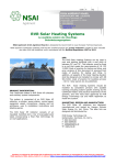
1
Victrix Zeus Superior 26/32kW Instructions
VICTRIX ZEUS SUPERIOR 26/32 kW
Instruction Booklet
Eco-friendly wall-hung condensing boilers
with stainless steel storage tank
Read these instructions completely before using or installing the
Victrix Zeus Superior 26/32kW gas boilers
LEAVE THESE INSTRUCTIONS WITH THE USER
For Technical assistance, spare parts or service call:
RVR Energy Technology Limited, Kenmare, Co. Kerry Tel: 064 41344, Fax: 064
89520
Doc. Ref.: ALT123/220509
Page
Victrix Zeus Superior 26/32kW Instructions
Introduction
The Victrix Zeus Superior 26/32kW boilers are condensing wall hung, room sealed combination boilers incorporating a 54 litre stainless steel unvented hot water storage cylinder. This boiler has the highest efficiency possible for a gas boiler, i.e. 4 stars (****) in conformity with European Directive 92/42 EEC.
The boiler, providing both central heating and domestic hot water supply, is designed for use with a fully
pumped, sealed and pressurised heating system using Natural Gas or LPG. The boiler is supplied for use
with one of these gas types and must be converted before it can be used on another gas. A boiler equipped
for natural gas must not be used on LPG or vice versa.
The boiler is supplied with a pump, diverter valve, automatic bypass, pressure relief valve, expansion vessel
and pressure gauge fully assembled and tested.
As supplied, the boiler will automatically modulate to provide central heating outputs between 4.7 and
20.0kW for the 26kW model and 6.9 to 32kW for the 32kW model. The maximum output available for domestic hot water is 26.9 kW for the 26kW model and 33kW for the 32kW model and the boiler provides hot
water at temperatures of up to 60°C.
IMPORTANT
All gas appliances must be installed by a competent and qualified person, in accordance with relevant
clauses of applicable standards and recommendations. These include but may not be limited to the following:I.S. 813 Domestic Gas Installations
I.S, 820 Non-Domestic Gas Installations
All relevant Building Regulations.
Local Water Bye Laws
IEE Wiring Regulations
Health & Safety legislation
This appliance meets the requirements of IPX5D, i.e. degree of protection against moisture.
Failure to install this appliance correctly could lead to prosecution. It is in your own interest and that of
safety to ensure that the law is complied with. Manufacturer's instructions must NOT be taken in anyway as
over-riding statutory obligations.
Carbon Monoxide
Every year there are several deaths and serious injuries in Ireland due to carbon monoxide poisoning. These
are avoidable if certain preventative measures are taken.
1. Ensure all boilers, heaters, stoves and hobs which burn oil, natural gas, LPG, coal, peat, wood and wood
2.
pellets are serviced regularly. Servicing is needed at least once per year to ensure safety. The service person should be qualified and trained to service the specific type of boiler or heater.
If a boiler or heater is fitted in a dwelling, then a carbon monoxide detector should always be fitted.
There are two types available:
A simple detector will work like a fire alarm and emit an alarm if carbon monoxide is detected.
A more sophisticated type will also switch off the heater or boiler ensuring complete safety.
RVR Energy Technology recommends that a carbon monoxide detector is installed in all dwellings
where any type of boiler, heater or other combustion appliance is installed.
Please call 064 6641344 or email [email protected] for more information or to have a detector installed.
Page 2
Victrix Zeus Superior 26/32kW Instructions
Boiler Operating Instructions
Figure 1– Boiler display
- Stand-by - On Button
A - Summer and winter
B - Domestic hot water priority Activation Button
C - (RESET) / menu exit (ESC) reset button.
D - Menu entry button (MENU)/ data confirmation (OK)
1 - Domestic hot water temperature selector switch
2 - Domestic hot water temperature set
3 - Central heating temperature selector switch
4 - Central heating temperature set
5 - Presence of faults
6 - Display of boiler functioning status
8 - Flame presence symbol and relative power scale
9 and 7 - Primary heat exchanger output water temperature
10 - Boiler in stand-by
11 - Boiler connected to remote control (Optional)
12 - Functioning in summer mode
13 - Anti-freeze function in progress
14 - Functioning in winter mode
15 - Domestic hot water priority functioning active
16 - Connection to external tools for technician
16 - Display of menu items
18 - Functioning with external temperature probe active
19 - Display of data confirmation or menu access
20 and 7
-External temperature display with external probe
connected (optional)
21 - Display of reset or exit menu request
22 - Chimney sweep function in progress
23 - Boiler manometer
24 - Multi-function display
Using the Boiler
Before lighting, make sure that the system is full of water and that the manometer (23) indicates a pressure of
1 - 1.2 bar.
Open the gas valve on the gas supply to the boiler.
The boiler is turned on and off by pressing button .
Press button A to switch to either Summer or Winter Heating.
N.B.: With button A set to summer, the central heating temperature setting is not active, and the domestic water temperature is controlled by selector (1). With the switch set to the central heating temperature is set using
selector (3) while selector (1) is used for the domestic hot water. Turn the selectors clockwise to raise the temperature, anticlockwise to lower it. Boiler operation is now automatic.
Button A - The boiler operating mode may be changed from the summer mode to winter mode by repeatedly
pressing button A. In summer mode, the DHW heating is active and central heating is not available. In winter
mode both central heating and direct hot water are available. The currently selected operating mode is shown
on the bottom of the LCD display.
Button B - Button B is used to override the hot water priority function B may be pressed until the DHW symbol
disappears from the left side of the LCD display. When this happens the boiler will function in central heating
mode only.
Button C is used to reset faults and also to exit the boiler menu system.
Selector switch (1) — used to adjust the DHW heating temperature from 20oC to 60oC. The set temperature is
displayed on the left side of the display during adjustment.
Selector switch (5) - used to adjust the central heating temperature from 25oC to 85oC. The set temperature is
displayed on the right hand-side of the LCD display during adjustment.
Page 3
Victrix Zeus Superior 26/32kW Instructions
Boiler Technical Data
PERFORMANCE:
Nominal Heat Input (DHW)
Nominal Heat Output (Central Heating)
Min. Heat Input
Nominal Heat Output (useful) (DHW)
Nominal Heat Output (useful) (Central Heating)
Min. Heat Output (useful)
GAS:
Nozzle diameter
Supply Pressure
Kw
Victrix Zeus Superior 26
26.9
Victrix Zeus Superior 32
33
20.8
33
Kw
5.0
7.3
Kw
25.8
32
20
32
Kw
mm
Mbar
4.7
6.9
G20
G30
G31
G20
G30
G31
5.7
20
4.1
29
4.1
37
20
6.0
29
6.0
37
HEATING SYSTEM:
Max Operating Pres. of Heating Unit
bar
3
3
Max Operating Temp. of Heating Unit
ºC
90
90
Adjustable Heat Temp (range 1)
Adjustable Heat Temp (range 2)
Total Volume of heating expansion vessel
Expansion Vessel precharge
Generator Water Capacity
ºC
°C
l
bar
l
25 - 85
25 - 50
25-85
25-50
7.1
1.0
Total volume of DHW expansion vessel
DHW expansion vessel pre-charge
l
bar
1.2
2.5
7.1
1.0
9.1
1.2
2.5
Available head capacity 1000 l/h
Working Heat Output d.h.w production
DHW adjustable temperature
Flow Limiting Device
DHW circuit minimum pressure
DHW circuit max operating pressure
Specific capacity D according to EN6625
kPa
Kw
ºC
l/min
bar
bar
l/min
18.7
26.9
20-60
35.5
33.0
20-60
10
0.3
8
16
14
0.3
8
19.2
Continuous flow rate ∆T 30ºC
Minimum pressure for flow limiting device
rated capacity
Full boiler Weight
Empty boiler weight
ELECTRICAL:
l/min
bar
13.1
1.0
15.3
1.0
kg
kg
76.8
70.1
81.9
72.8
Power Connection
Rated Power Input
Installed Electrical Power
Power absorbed by circulation pump
Power absorbed by fan
Appliance electrical system callout
FLUE GASES:
v/hz
A
W
W
W
G20
230/50
0.57
110
74.7
24.4
IPX5D
G30
G31
230/50
0.65
135
98.6
29
IPX5D
G30
Rated power fume mass flow
Minimum power fume mass flow
CO2 at nominal output
CO2 at minimum output
CO at O% O2 at nominal output
NOx at 0% of 02 at nominal output
Temperature of fumes at rated output (50/30)
kg/h
kg/h
%
%
ppm
ppm
ºC
43
8
9.4
8.9
200/7
39/22
78
39
7
12.0
11.8
670/11
108/50
86
43
8
10.6
10.2
270/7
43/30
79
Temperature of fumes at min. output (50/30)
ºC
73
82
75
6.7
G20
52
G31
9.4
8.9
206/9
47/24
73
47
11
12.3
11.9
640/8
158/51
82
53
12
10.5
10.3
190/8
57/30
74
64
72
66
12
Table 1— Technical Data
Page 4
Victrix Zeus Superior 26/32kW Instructions
Main Boiler Components
Gas
12 3 4 5 67 8 9 10 11 12 13 14 15 16 -
System
Return
System
Flow
System filling valve
Condensate drain trap
System draining valve
Gas valve
Three-way valve (motorised)
3 bar safety valve
System pressure switch
Boiler pump
Vent valve
Fan
Gas nozzle
Venturi
Detection electrode
Condensation module
Flue safety thermostat
Air intake pipe
DHW Cold water
Outlet inlet
17 - Sample points (air A) - (fumes F)
18 - Negative signal pressure point
19 - Burner
20 - Positive signal pressure point
21 - Manual vent valve
22 - Ignition electrodes
23 - System expansion vessel
24 - Flow probe
25 - Safety thermostat
26 - Domestic hot water probe
27 - D.H.W. expansion vessel
28 - Return probe
29 - Stainless steel cylinder
30 - 8 bar safety valve
31 - Cylinder draining valve
Figure 2—Boiler Main Components
Page 5
Victrix Zeus Superior 26/32kW Instructions
Hydraulic Layout
1 - Condensate drain
1 - Stainless steel coil for cylinder
3 - Magnesium anode
4 - Stainless steel cylinder
5 - Gas valve
6 - Gas valve outlet pressure point (P3)
7 - Air/gas Venturi collector
8 - Fan
9 - Gas nozzle
10 - Detection electrode
11 - Flue safety thermostat
12 - Air intake pipe
13 - Condensation module
14 - Manual vent valve
15 - Fumes hood
16 - Air sample point
17 - ∆p gas pressure point
18 - Flue sample point
19 - Flow probe
20 - Safety thermostat
21 - Burner
22 - Igniton electrodes
23 - Condensation module cover
Figure 3—Hydraulic Layout
23 - Venturi negative sign (P2)
25 - Venturi positive sign (P2)
26 - Return probe
27 - System expansion vessel
28 - Boiler pump
29 - Adjustable by-pass
30 - System pressure switch
31 - System draining valve
32 - Three-way valve (motorised)
33 - Domestic hot water probe
34 - 3 bar safety valve
35 - System filling valve
36 - D.H.W. expansion vessel
37 - 8 bar safety valve
38 - Cold water inlet non-return valve
39 - Cylinder draining valve
G - Gas supply
SC - Condensate drain
AC - Domestic hot water outlet
AF - Domestic hot water inlet
R - System return
M - System flow
Page 6
Victrix Zeus Superior 26/32kW Instructions
General Installation Information
Gas Supply
The meter and supply pipes must be sized to deliver the gas rate and pressure given on page 4. The
boiler requires at least a 22 mm (3/4”) gas supply pipe. The complete installation, including the meter, must
be tested for gas soundness and purged as described in IS 813:2002.
Electrical Installation
The boiler requires a 220/240 V ~ 50
Hz mains supply, fused at 3 A. The
boiler must be earthed. The polarity of the supply must be correct as
otherwise the boiler will not operate
properly.
There must only be one common isolator, providing complete electrical
isolation, for the boiler and any
external controls. Using PVC
insulated cable not less than 0.75
mm² (24 x 0.2 mm) to BS 6500
Table 16, the boiler should be
connected to a fused three pin plug
and unswitched shuttered socket outlet (both complying with BS 1363), or
a fused double pole switch with a
contact separation of at least 3 mm
in both poles.
Wiring external to the boiler must
be in accordance with the current IEE
Wiring Regulations.
Optional Immergas
Remote controller
(CAR)
Replace link with volt free
contact from CH controls.
Do not connect 220V!
External weather compensation sensor
Figure 4—Electrical Installation
Note: External controls connected to the boiler must be of the volt free type and are connected to
terminals 40 and 41 as shown above.
Weather Compensation
A temperature sensor for outdoors is available as an optional accessory for the boiler. This should be fitted
in an outdoor location which is not exposed to direct sunlight. A north facing wall is a good location.
If the optional weather compensation sensor is used, it should be connected to terminals 38 and 39 as
shown above using a two core cable. If this cable is routed in close proximity to cables carrying mains voltages, then screened cable should be used. Contact RVR for more information.
When the sensor is connected, the boiler adapts it’s flow temperature to suit the prevailing weather conditions. This results in lower energy usage and enhanced comfort.
WARNING ! - Connection of a voltage to any boiler terminals other than the mains
lead will result in destruction of the boiler control panel. The product warranty
does not cover this type of damage.
Clearances and Air Supply
The boiler does not require any air vents for cooling in the room in which it is installed or when installed in a
cupboard or compartment. The minimum clearances for servicing must always be maintained. Please see
table on page 14. Note: A cupboard or compartment used to enclose the boiler must be designed and
constructed specifically for the purpose.
Page 7
Victrix Zeus Superior 26/32kW Instructions
Boiler Dimensions
Boiler Dimensions
Height
Depth
Width
900mm
466mm
600mm
Figure 5—Boiler Dimensions
V G SC R M RC AC AF -
Electric connection
Gas supply
Condensate drain (minimum internal diameter Ø 13 mm)
System return
System flow
Domestic hot water pump (optional)
Domestic hot water outlet
Domestic hot water inlet
Boiler Connections
Boiler Connections
Gas Connection
CH Connection
DHW Connection
Figure 6—Lower view
1 23 4 5 6 -
½”
¾”
½”
Lower view
System filling valve
System draining valve
Cold water inlet valve
Gas cock
Cylinder draining valve
Page 8
Victrix Zeus Superior 26/32kW Instructions
Flue Systems
When the boiler is installed on an external wall, the standard horizontal concentric 60/100 flue kit will normally
be used to flue the boiler. This is shown in the diagram.
It is often necessary to install a longer flue system to cater for site conditions. There are several different flue
system sizes available for the Victrix Zeus 20/27 boiler.
Horizontal concentric kit 60 /100
Install the bend with flange (2) on the left hole of the boiler inserting the seal (1) with the round protrusions facing downwards in contact with boiler flange and tighten using the screws supplied with
the kit.
Fit the smooth male end of the 60/100 concentric terminal pipe (3)
until it reaches to the stop on the female end of the bend (2), making sure the internal and external sealing rings are fitted; this will
ensure the connection is properly sealed. Additional extensions
and bends may be installed if required using the same method.
Ensure that all seals are fitted and that the outer and inner pipes The kit includes:
are installed so that all joints are perfectly sealed. Ensure that the N° 1 - Gasket (1)
N° 1 - Concentric bend Ø 60/100 (2)
terminal is installed the right way up.
A lubricant may assist in overcoming the friction of the seals. Oils
and conventional greases are not compatible with the EPDM seals
used and should never be used for this purpose. Talc may be
used. Please contact RVR for more information.
A rigid supporting clamp should be fitted on each 1.0 metre or 2.0
N° 1 - Concentric terminal int./exhaust Ø
60/100 (3)
N° 1 - Internal white wall sealing plate (4)
N° 1 - External grey wall sealing plate (5)
Figure 7—Horizontal concentric kit
metre flue extension in all cases. The flue system should be inclined at a minimum slope of 1% so that condensate flows towards the boiler. The elbow above the boiler is the low point of the flue system and the terminal at
the outside wall is the high point of the system. The fall should be continuous over the full length of the flue system and the there should be no low points which would allow condensate to build up within the flue pipes. This
avoids any drips from the external flue terminal.
The maximum possible overall length after the first bend (2)
is 12.9 straight and horizontal meters. See the section on
extended flue design for more information.
Vertical concentric kit 60 /100
Install the concentric flange (2) on the left hole of the boiler inserting the seal (1) with the round protrusions facing downwards
in contact with boiler flange and tighten using the screws supplied with the kit.
Fit the male end (smooth) of the adapter (3) in the female end of
the concentric flange (2) until it reaches the stop on the female
end of the flange, making sure the internal and external sealing
rings are fitted; this will ensure the connection is properly sealed.
Additional extensions and bends may be installed if required using the same method.
Installing the flashing- Replace tiles with the aluminium sheet (5),
shaping it to ensure that the rainwater runs off. Position the fixed
half-shell (7) on the aluminium tile and insert the intake/exhaust
pipe (6). Fit the male end (6)(smooth) of the 60/100 concentric
terminal up to the stop on the female end of the adapter(3),
The kit includes :
N° 1 - Gasket (1)
N° 1 - Female
concentric flange (2)
N° 1 - Wall sealing
plate (3)
N° 1 - Aluminium
tile (4)
N° 1 - Concentric
terminal int./exhaust
Ø
60/100 (5)
N° 1 - Fixed halfshell (6)
N° 1 - Mobile halfshell (7)
Figure 8—Vertical concentric kit
making sure that the ring (4) is already fitted; this will ensure hold and joining of the elements making up the kit.
Ensure that all seals are fitted and that the outer and inner pipes are installed so that all joints are perfectly
sealed. A lubricant may assist in overcoming the friction of the seals. Oils and conventional greases are not compatible with the EPDM seals used and should never be used for this purpose. Talc may be used. Please contact
RVR for more information.
A rigid supporting clamp should be fitted on each 1.0 metre or 2.0 metre flue extension in all cases.
The maximum possible overall length including the terminal is 14.4 straight and horizontal meters.
NB: If the terminal or extension pipes need shortening ensure that the inner pipe protrudes by 5mm with
Page 9
Victrix Zeus Superior 26/32kW Instructions
Separated Flue Systems
Separated 80/80 flue kit
This kit enables separation of the exhaust and air intake
pipes as shown in figure 9.
Combustion products are expelled from pipe (A) (in
plastic material resistant to acidic condensates). Air is
taken in through pipe (B) (also in plastic material) for
combustion.
Intake pipe (B) can be installed either on the right or left
hand side of the central exhaust pipe (B). Both pipes
can be oriented in any direction.
Assembly:
Install the flange (4) on the left hole of the boiler inserting the seal (1), positioning it with the round protrusions
downwards in contact with the boiler flange and tighten
using the screws supplied with the kit.
Remove the sealing plate from the air intake and replace it with flange (3)inserting seal (2) which is already
fitted on the boiler and tighten using the screws supplied.
Insert bends (5) with the male end (smooth) in the female end of the flanges (3&4). Fit the male end of the
intake terminal (6) up to the stop on the female end of
the bend (5), making sure that the relevant internal and
external sealing rings are fitted. Fit the male of the exhaust pipe up to the stop on the female end of the bend,
making sure that the internal sealing ring is fitted; this
will ensure a seal and joining of the elements making up
the kit.
The kit includes:
N° 1 - Exhaust gasket (1)
N° 1 - Flange seal (2)
N° 1 - Female intake flange (3)
N° 1 - Female exhaust flange (4)
N° 2 - Bend 90° Ø 80 (5)
N° 1 - Intake terminal Ø 80 (6)
N° 2 - Internal white wall sealing plates (7)
N° 1 - External grey wall sealing plate (8)
N° 1 - Exhaust pipe Ø 80 (9)
Figure 9—Separated flue kit
A lubricant may assist in overcoming the friction of the seals. Oils and conventional greases are not compatible with the EPDM seals used and should never be used for this purpose. Talc may be used. Please
contact RVR for more information.
A rigid supporting clamp should be fitted on each 1.0 metre or 2.0 metre flue extension in all cases. The flue
system should be inclined at a minimum slope of 1% so that condensate flows towards the boiler. The elbow above the boiler is the low point of the flue system and the terminal at the outside wall is the high point
of the system. The fall should be continuous over the full length of the flue system and the there should be
no low points which would allow condensate to build up within the flue pipes. This avoids any drips from the
external flue terminal.
The maximum possible overall length without any bends is 36 straight, horizontal meters or 41
straight, vertical meters regardless of whether they are used in intake or exhaust. See the section
on extended flue design for more information.
Page 10
Victrix Zeus Superior 26/32kW Instructions
Flue Calculations for More Complex Systems
Each component of the air inlet/flue system has a resistance factor . These are given in the following tables.
The resistance factor varies depending on whether the component in question conveys fresh inlet air or hot
combustion gases. All boilers have a maximum resistance factor of 100. The sum of all components in the
flue system must not exceed the maximum overall resistance factor of 100.
Page 11
Victrix Zeus Superior 26/32kW Instructions
Flue Calculations for More Complex Systems
Table 2—Flue calculations
Component
Resistance
Quantity Total
80mm Intake pipe
0.87
9
7.83
90˚ air intake bend
1.9
3
5.7
80mm Flue pipe
1.2
6
7.2
90˚ Flue bend
2.6
2
5.2
Total Flue Resistance 25.93
Example:
Flue system consists of 9m of 80mm air intake pipe with
3 x 90˚ bends and 6m of exhaust pipe with 2 x 90˚ bends.
Component Resistances:
In this case the total resistance of the system is less
than 100. The flue design is acceptable.
Table 3—Component resistances
Page 12
Victrix Zeus Superior 26/32kW Instructions
Flue Terminal Location
Terminal Position
Min. Distance
A Directly below an opening, air brick, windows, etc.
B Below gutters, soil pipes or drain pipes
C Below eaves
D Below balconies or car port roof
E From a vertical drain pipe of soil pipe
F From an internal or external corner
G Above ground, roof or balcony level
H From a surface facing the terminal
I From a terminal facing a terminal
J From an opening in the car port (door, window) into dwelling
K Vertically from a terminal on the same wall
L Horizontally from a terminal on the same wall
M Horizontally from an opening, air brick, window etc.
Below horizontally hinged windows where exhaust is directed upwards
Below horizontally hinged windows where exhaust is not directed upwards
300 mm
75mm
75mm
75mm
75mm
75mm
300mm
600mm
1200mm
1200mm
1500mm
300mm
300mm
3000mm
1000mm
Figure 10—Flue terminal location
The flue terminal must be exposed to the external air and the
position must allow the free passage of air across it at all times. In certain weather conditions the terminal
may emit a plume of steam. Avoid positioning the terminal where this may cause a nuisance. If the terminal
is fitted within 850 mm of a plastic or painted gutter or 450 mm of painted eaves or 300 mm of a plastic car
port roof, an aluminium shield at least 1 m long should be fitted to the underside of the gutter or painted surface. If the terminal is fitted less than 2 m above a surface to which people have access, the terminal must
be protected by a terminal guard.
IMPORTANT— Failure to install flue systems correctly may lead to serious injury or death. Ensure
that:
•
Only flues specifically designed for condensing boilers and provided by RVR Energy Technology
Limited are used.
•
The flue slopes slightly towards the boiler by between 1 and 2 degrees to ensure any condensate
flows towards the boiler. Failure to do this will result in condensate dripping from the flue terminal.
•
The flue is adequately supported along it’s length so that it is straight and cannot be moved without
using a tool.
•
The flue system has no low points where condensate can collect.
•
All flue terminals are securely fixed.
•
No chemicals, detergents, solvents or liquids of any kind are used in the assembly of the flue system.
Talc may be used as a lubricant where necessary.
•
All joints and connections are properly assembled to prevent leakage and all seals are properly
seated.
•
The flue is thoroughly tested for leaks after installation.
•
The seals are correctly seated in all joints. Failure to ensure this will cause distortion and leaking of
the flue system.
Page 13
Victrix Zeus Superior 26/32kW Instructions
Boiler Location
Boiler Location
The boiler is not suitable for external installation.
The boiler must be installed on a flat vertical wall which is capable of supporting the weight of the boiler.
The boiler can be fitted to or adjacent to a wall comprising of a combustible material without the need for a
special thermal insulation barrier.
The boiler may be installed in any room or internal space, although particular attention is drawn to the requirements of the current IEE Wiring Regulations. Where a room sealed boiler is installed in a room containing a bath or shower, it must not be possible for a person using the bath or shower to touch any electrical switch or boiler control utilising mains electricity.
The boiler may be installed in a cupboard or compartment, provided it is correctly designed for that purpose.
Minimum Clearances for Servicing:
Top
200
Bottom
150
Side
25
Front
600
Table 4 - Clearances for servicing
Page 14
Victrix Zeus Superior 26/32kW Instructions
Central Heating System
The boiler is designed for use in a sealed central heating system. The system should be designed to operate with flow temperatures of up to 80°C. When designing the system, the pump head, expansion vessel
size, mean radiator temperature, etc. must be taken into account.
The pressure losses in the system must be compatible with the boiler circulation pump. See pump performance graph below:
Pump performance curves
Flow—Head Graph:
The pump head depends on how the system bypass is adjusted.
Victrix Zeus Superior 26kW
Victrix Zeus Superior 32kW
Figure 11– Flow-head graph
A = Head available to the system on the third speed with by-pass closed (adjustment screws tightened fully
home)
B = Head available to the system on the second speed with by-pass closed (adjustment screws tightened fully
home)
C = Head available to the system on the first speed with by-pass closed (adjustment screws tightened fully
home)
D = Total head available to the plant on the third speed (screws tightened by 1.5 revs with respect to the completely loose adjustment screws).
E = Total head available to the plant on the second speed (screws tightened by 1.5 revs with respect to the
completely loose adjustment screws).
F = Total head available to the plant on the first speed (screws tightened by 1.5 revs with respect to the completely loose adjustment screws)
System volume - The 7.1 litre expansion vessel incorporated into the boiler is pre-charged to 1.0 bar and is
suitable for a sealed heating system with a maximum water content of 71 litres. Above 71 litres, consideration should be given to fitting an additional expansion vessel. To check correct operation of the expansion
vessel (s) the system pressure should not be more than 2.5 bar when the system is at maximum operating
temperature.
The boiler is supplied with the following components built in:Central Heating Pressure relief valve - complying with BS 6759 and set to operate at 3 bar. The discharge
pipe must be routed clear of the boiler to a drain, so that it can be seen, but cannot cause injury to persons
or property.
A Pressure gauge is included to indicate the pressure of the central heating system.
Page 15
Victrix Zeus Superior 26/32kW Instructions
Plumbing of the Victrix Zeus Superior
The most important components of the system are shown in the diagram below.
•
The cold water supply for the water heating side of the system may come from a booster pump or the
cold water mains where this is permitted by the local authority.
•
A non-return valve must be installed on the cold feed to the boiler. This prevents expanding hot water back-feeding into the cold side of the system.
•
The boiler includes an automatic bypass. It is not necessary to make any further provision for system
bypasses.
•
The boiler condensate outlet must be connected to a drain. Metal pipes must not be used for this
purpose as the slightly acidic condensate will lead to rapid corrosion. Plastic must be used for this
purpose.
Superior
Figure 12—Plumbing of the Victrix Zeus Superior
Filling the central heating system
The system design pressure (cold) should be set to 1.0 bar. This pressure is equivalent to a static head of
10.2 metres of water. Provision should be made to replace water lost from the system. This can be by
manual or automatic means.
Filling of the system must be carried out in a manner approved by the local authority. Where allowed, the
system may be filled via a temporary connection as shown below or by using the integrated filling valve in
the boiler. After filling, always disconnect the flexible hose of the filling loop if used and close the filling
valve in the boiler.
All fittings used in the system must be able to withstand pressures up to 3 bar. Drain taps (to BS 2879)
must be used to allow the system to be completely drained. The heating system should be thoroughly
flushed before the boiler is connected and again after the first heating. If it is necessary to add inhibitor to
the central heating system, contact RVR Ltd. for guidance.
Figure 13—Filling the Central Heating System
Page 16
Victrix Zeus Superior 26/32kW Instructions
Domestic Hot Water System
Mains water pressurised unvented system are generally not permitted in Ireland. A cold water storage tank
and a pressure boosting pump will normally provide a pressurised cold water supply. The pressurisation
pump should provide a water pressure of between 1 and 3 bar. However, all taps and mixing valves used
with the hot water system must be suitable for operating at a pressure of up to 5.5 bar. The use of fittings
designed for open, low pressure systems should be avoided as this will lead to excessive water flow rates.
To ensure economic use, the pipe runs between the boiler and taps should be in 15 mm copper pipe and be
as short as possible. Where possible the pipe work should be insulated to reduce heat loss.
Before the cold water supply pipe is connected to the boiler, it should be thoroughly flushed out to avoid the
danger of dirt or foreign matter entering the boiler.
The stored water temperature is adjustable to a maximum of 55°C. In hard water areas this should avoid
possible scale build-up. However, if descaling is necessary contact RVR Limited for guidance.
Unvented Hot Water Storage System
The installation is subject to Building Regulations and the Water Bye Laws of the Local Authority.
The Victrix Zeus Superior 26/32kW boiler is supplied with all the components required for a safe and efficient unvented hot water system. An air cushion which is present at the top of the 54l storage vessel provides some of the expansion for the domestic hot water system. The balance is provided by the additional
DHW expansion vessel installed within the boiler casing.
NOTE: In the Dublin City Council area, the council requires that the minimum internal diameter of
pipes connected to the boiler DHW connections should not be less that 13mm. As 1/2” thermoplastic pipe does not provide the minimum diameter, the minimum suitable thermoplastic pipe size is
3/4”
Discharge pipe - The discharge pipes from the expansion relief valves must be routed to a tundish in
1/2” (or 15 mm )pipe. The discharge pipe work from both relief valves may be joined together in the same
sized pipe, providing at least 3/4” (or 22 mm) pipe work is connected downstream of the tundish.
Superior Boiler
Zeus
Superior
Boiler
Figure 14– Unvented Hot Water Storage System
Tundish - The tundish must be positioned within 500 mm of the appliance, so that it is visible to the user
and away from electrical devices. The minimum size of the discharge pipe downstream of the tundish is
given in the following table.
22mm (3/4”)
15mm (1/2”)
28mm (1”)
35mm (11/4”)
Table 5—Sizing of copper discharge pipe
Page 17
Victrix Zeus Superior 26/32kW Instructions
Tundish Installation
The discharge pipework from the tundish:1. Shall fall continuously through its length.
2. Shall be of a heat resistant material, e.g. metal.
3. Shall not be fitted with any valves or taps.
4. Shall discharge to a safe visible position, e.g. onto the surface of an external wall or into a gulley.
5. Shall have a minimum of 300 mm straight pipework directly from the tundish.
Note: Where children may play or otherwise come into contact with discharges, a wire cage or similar
guard must be positioned to prevent contact whilst maintaining visibility.
Please see the diagrams below for suggested methods of terminating the discharge pipe safely. Where a
single pipe serves a number of discharges, such as in blocks of flats, the number served should be limited
to not more than 6 systems so that any installation can be traced reasonably easily. The single common
discharge pipe should be at least one pipe size larger than the largest individual discharge pipe to be connected. If the system is installed where discharges from safety devices may not be apparent, i.e. in dwellings occupied by blind, infirm or disabled people, consideration should be given to the installation of an
electronically operated device to warn when discharge takes place.
Figure 15– Tundish installations
High Level Termination
At high level, discharge onto a roof is acceptable providing the roof is capable of withstanding high temperatures and there is a distance of 3 m from any
plastic guttering systems that would collect such disExample:The example below is for a G½ temperature relief valve with a
discharge pipe (D2) having four elbows and a length of 7 m from the
tundish to the point of discharge.
From Table 5:Maximum resistance allowed for a straight length of 22 mm copper discharge pipe (D2) from a G½ temperature relief valve is 9 m. Subtract the resistance for four 22 mm elbows of 0.8 m each = 3.2 m. Therefore the
maximum permitted length equates to 9 - 3.2 = 5.8 m
5.8 m is less than the actual length of 7 m therefore calculate the next largest size.
Maximum resistance allowed for a straight length of 28 mm pipe (D2) from a G½ temperature relief valve
equates to 18 m.
Subtract the resistance for four 28 mm elbows at 1.0 m each = 4 m.
Therefore the maximum permitted length equates to 18 - 4 = 14 m
As the actual length is 7 m, a 28 mm (D2) copper pipe will be satisfactory.
Page 18
Victrix Zeus Superior 26/32kW Instructions
Fault Signals
Fault
Code
Ignition block
01
Safety thermostat block (over temperature) flame control fault
02
Flue safety thermostat block
03
Contacts resistance block
04
Flow probe fault
05
Insufficient system pressure
10
Cylinder probe fault
12
Configuration error
15
Fan fault
16
Parasite flame block
20
Return probe fault
23
Push button control panel error
24
Insufficient circulation
27
Loss of remote control communication
31
Low power supply voltage
37
Loss of flame signal
38
Table 6—Fault Signals
Important: the error codes 31, 37, 38 are not shown on the CAR and Super CAR display.
1. Ignition block. The boiler ignites automatically with each demand for room central heating or hot water
production. If this does not occur within 10 seconds, the boiler remains in stand-by for 30 seconds, try
again and if the second attempt fails it will go into “ignition block” (ERR01). To eliminate “ignition block”
the Reset button “C” must be pressed. The fault can be reset 5 times consecutively, after which the function in
inhibited for at least one hour. One attempt is gained every hour for a maximum of 5 attempts. By switching the
appliance on and off the 5 attempts are re-acquired. On commissioning or after extended inactivity it may be
necessary to eliminate the “ignition block”. If this occurs frequently, contact a qualified technician for assistance.
2. Safety thermostat block (over-temperature). During operation, if a fault causes excessive overheating internally, or an error occurs in the flame control section, an over-temperature block is triggered in the boiler
(ERR02). To eliminate “over-temperature block” the Reset button “C” must be pressed. If this occurs frequently,
contact a qualified technician for assistance.
3. Flue safety thermostat block This occurs in the case of partial internal obstruction (due to the presence of lime scale or dirt) or external blocking (combustion residues) in the condensation module. To eliminate the “flue safety thermostat block” the Reset button “C” must be pressed. Call an authorised technician
to remove the obstructions.
4. Contacts resistance block. This occurs in the case of faults to the safety thermostat (over-temperature) or
fault in the flame control. The boiler does not start and a technician must be called.
5. Flow probe error. If the board detects an error on the system NTC flow probe (code 05) the boiler will not
start; contact a qualified technician for assistance.
10. Insufficient system pressure. Water pressure inside the central heating system that is sufficient to guarantee the correct functioning of the boiler is not detected. Check on the boiler manometer (1) that the system
pressure is between 1 - 1.2 bar and restore the correct pressure if necessary.
12. Cylinder probe fault If the board detects a fault on the cylinder probe, the boiler cannot produce domestic
hot water. A qualified technician must be called for assistance.
15. Configuration error. If the board detects an error on the electric wiring on first power supply, the
boiler will not start. If normal conditions are restored the boiler restarts without having to be reset. The defect
Page 19
Victrix Zeus Superior 26/32kW Instructions
Fault Signals
could be due to a fault in the flue flow meter detected after restoring the electric mains voltage. If this persists, contact a qualified technician for assistance.
16. Fan fault. This occurs if the fan has a mechanical or electrical fault. To eliminate the “fan
fault” the Reset button “C” must be pressed. If this fault persists, contact a qualified technician for assistance.
20. Parasite flame block. This occurs in case of a leak on the detection circuit or fault in the flame control
unit. The boiler can be reset in order to allow a new ignition attempt. If the boiler does not start, contact a
qualified technician for assistance.
23. Return probe error. In this condition the boiler does not correctly control the pump if set as “Auto”.
The boiler continues functioning but to eliminate the error, contact a qualified technician for assistance.
24. Push button control panel fault. This occurs when the circuit board detects a fault on the
push button control panel. If normal conditions are restored the boiler restarts without having to
be reset. If this fault persists, contact a qualified technician for assistance.
27. Insufficient circulation. This occurs if there is overheating in the boiler due to insufficient water
circulating in the primary circuit; the causes can be:
- low circulation; check that no interception devices are closed on the central heating circuit and that
the system is free of air (deaerated);
- circulating pump blocked; free the circulating pump.
If this occurs frequently, contact a qualified technician for assistance.
31. Loss of remote control communication. This occurs in the case of connection to a remote
control that is not compatible or if there is a loss of communication between the boiler and CAR remote control or Super CAR remote control. Try the connection procedure again by turning the boiler off and then
back on again. If the Remote Control is still not detected on re-starting the boiler will switch to local
operating mode, i.e. using the controls on the boiler itself. In this case the boiler cannot activate
the “CH ON” function. To make the boiler function in “CH ON” mode, activate the “P33” function present inside the “M3” menu. If this occurs frequently, contact a qualified technician for assistance.
37. Low power supply voltage This occurs when the power supply voltage is lower than the allowed limits
for the correct functioning of the boiler. If normal conditions are restored, the boiler restarts without having
to be reset. If this occurs frequently, contact a qualified technician for assistance.
38. Loss of flame signal. This occurs when the boiler is ignited correctly and the burner flame switches off
unexpectedly; a new attempt at ignition is performed and if normal conditions are restored, the boiler
does not have to be reset (this error can be checked in the list of errors P19 present in the “M1” menu). If
this incident occurs frequently, contact a qualified technician for assistance.
Other maintenance operations :
Lack of water in boiler.
Not enough water pressure detected in the heating circuit to guarantee correct boiler operation. Make sure
that the pressure in the system is between 1 and 1.2 bar. N.B. Close the valve on completion. If pressure
valves reach around 3 bar the safety valve may be activated. In this case contact a professional technician
for assistance. In the event of frequent pressure drops, contact qualified personnel for assistance to eliminate system leakage.
System flow NTC sensor fault.
If the unit detects a problem with the system delivery NTC sensor, the boiler will not start; call a qualified
technician.
Domestic circuit NTC sensor fault.
If the unit detects a problem in the domestic circuit NTC sensor, the boiler will not produce domestic hot
water; call a qualified technician.
No water circulating.
This occurs if there is overheating in the boiler due to insufficient water circulation through the boiler - check
that no shutoff devices are closed and that the system is free of air . Check that the circulating pump is running freely. If necessary, remove the pump cover screw and manually rotate the pump impellor using a flat
bladed screwdriver. If lockout occurs repeatedly, contact a qualified technician for assistance.
Draining the system.
To drain the boiler, use the special drain cock. Before draining, ensure that the filling valve is not connected closed.
Draining the boiler.
To drain the boiler, use the special drain cock. N.B.: Before carrying out this operation, close the boiler cold
Page 20
water inlet cock and open any domestic circuit hot water cock to allow air to enter the boiler.
Victrix Zeus Superior 26/32kW Instructions
Using the Boiler
Warnings
Never expose the wall-mounted boiler to direct vapours from a cooking surface. Use of the boiler by unskilled persons or children is strictly prohibited.
Never touch the flue extraction terminal (if fitted) due to the risk of burning caused by high temperatures;
For safety purposes, check that the concentric air intake/flue exhaust terminal (if fitted), is not blocked. If
temporary shutdown of the boiler is required, proceed as follows:
a) drain the heating system if anti-freeze is not used;
b) shut off all electrical, water and gas supplies.
When building or renovation work is carried out in the vicinity of the flue outlet, switch off the boiler and on
completion of work ensure that a qualified technician checks the safety of the installation. Never clean the
appliance or connected parts with flammable substances. Never leave containers or flammable substances
in the same environment as the appliance.
Electrical Safety
- never touch the appliance with wet hands or other parts of the body and never touch when barefoot.
- never pull electrical cables or leave the appliance exposed to atmospheric agents (rain, sunlight, etc.);
- the appliance power supply cable must never be replaced by the user;
- in the event of damage to the cable, switch off the appliance and contact a qualified service technician.
- in the event of prolonged periods when the boiler is not in use, turn off the main power switch.
Antifreeze functions:
The boiler is equipped with an anti-freeze system in both central heating and hot water modes:
When the temperature measured in the central heating system falls below 4 C, the boiler is automatically
fired until a boiler temperature of 35ºC is achieved.
When the temperature measured in the hot water tank falls below 4 C, the boiler is automatically fired until
a boiler temperature of 8ºC is achieved. The anti-freeze function is only guaranteed if:
- the boiler is correctly connected to gas and electricity power supply circuits;
- the boiler is powered constantly;
- the boiler is not in stand-by
- the boiler is not in no ignition block (See Error 01 on Page 19);
- the boiler essential components are not faulty.
In these conditions the boiler is protected against freezing to an environmental temperature of -5°C.
Weather compensation (Optional)
The boiler is prepared for the application of the external weather compensation probe, below, which is
available as an optional kit. The probe can be connected directly to the boiler electrical system and allows
the max. system flow temperature to be automatically decreased when the external temperature increases,
in order to adjust the heat supplied to the system according to the change in external temperature. The external probe always operates when connected, regardless of the presence or type of room thermostat used.
The correlation between system flow temperature and external temperature is determined by the parameters set in menu “M5” under “P66” according to the curves represented in the diagram (Figure 18). The
electric connection of the external probe must be made on clamps 38 and 39 on the boiler circuit board, see
wiring diagram page 28.
Figure 17—Weather compensation probe
Page 21
Victrix Zeus Superior 26/32kW Instructions
Description of Functioning States
SUMMER Summer functioning mode in progress without request. Boiler in stand-by for domestic hot
water request.
WINTER Winter functioning mode in progress without request. Boiler in stand-by for domestic hot water or central heating request.
DHW ON Domestic hot water mode in progress. Boiler functioning, domestic hot water heating in progress.
CH ON Central heating mode in progress. Boiler functioning, central heating in progress.
F3 Anti-freeze mode in progress. Boiler functioning to restore the minimum safety temperature against
boiler freezing.
CAR OFF Remote Control (Optional) off.
DHW OFF With domestic hot water priority disabled (indicator 15 off), the boiler only functions in room
central heating mode for duration of 1 hour, however keeping the domestic hot water at minimum temperature (20°C), after which the boiler goes back to the normal functioning, previously set.
In the case of use with Super CAR with the functioning period in reduced D.H.W. Timer mode, DHW
OFF will appear on the display and indicators 15 and 2 switch off (see Super CAR instructions manual).
F4 Post ventilation in progress. Fan in function after a request for domestic hot water or central heating in order to evacuate residual fumes.
F5 Post circulation in progress. Pump in function after a request for domestic hot water or central heating in order to cool the primary circuit.
P33 With Remote Control (Optional) or environment thermostat (TA) (Optional) in block, the boiler
functions all the same in central heating mode. (Can be activated through the “Customisation” menu. It
allows to activate the central heating even if the Remote Control or TA are out of order).
STOP Reset attempts finished. Wait for 1 hour to re-acquire 1 attempt. (See Ignition block Error 01).
ERR xx Fault present with relative error code. The boiler does not work. (see fault signals on page
20).
SET During the rotation of the domestic hot water temperature selector switch (1 Fig 16, page 19)
view the state of the adjustment of the domestic hot water temperature in progress.
During rotation of the central heating selector switch (3 Fig 16, page 19) the adjustment status of the
boiler flow temperature for central heating is displayed.
In presence of the external probe (optional) replace the
“SET” item.
The value that appears is the correction of the flow temperature with respect to the functioning curve set by the external
probe. See OFFSET on external probe graphics.
F8 System deaeration in progress.
During this phase, which lasts 18 hours, the boiler pump is
started at pre-established intervals, thus allowing deaeration
of the central heating system.
F9 Only in the case of use with Super CAR, does it allow to
activate the anti-legionella function, which takes the temperature of the water in the cylinder to 65°C for 15 minutes.
Figure 18— External probe graphic
(see Super CAR instruction manual).
Solar Panels Coupling Function
The boiler is designed to receive pre-heated water from a system of solar panels up to a maximum temperature of 65°C. In each case it is always necessary to install a mixer valve on the hydraulic circuit upstream from
the boiler. Set the “P71” function on “P71.2” (Page 31).
When the boiler inlet water is at a temperature that is equal or greater with respect to that set by the domestic
hot water selector switch “SET”, the boiler does not switch on.
Page 22
Victrix Zeus Superior 26/32kW Instructions
Using the Boiler
Summer: in this mode the boiler functions only to heat domestic hot water. The temperature
is set using the selector switch (1) and the relative temperature is shown on the display (24) by means of
the indicator (2) and the “SET” indication appears (Figure 19). By turning the selector switch (1) in a
clockwise direction the temperature increases and in an anti-clockwise direction it decreases.
Figure 19
“DHW ON” appears on the display (24) on the status indicator (6) and at the same time as burner
ignition the flame presence indicator switches on (8) with relative power scale and the indicator (9
and 7) with the instantaneous outlet temperature from the primary heat exchanger.
Figure 20
Winter: in this mode the boiler functions both for heating domestic hot water and central heating. The
temperature of the domestic hot water is always adjusted using the selector switch (1), the central
heating temperature is adjusted using the selector switch (3) and the relative temperature is shown on
the display (24) using the indicator (4) and the “SET” indication appears (Figure 21). By turning the selector switch (3) in a clockwise direction the temperature increases and in an anti-clockwise direction it
decreases.
Figure 21
Page 23
Victrix Zeus Superior 26/32kW Instructions
Using the Boiler
During the request for room heating “CH ON” appears on the display (24) on the status indicator (6) and at
the same time as burner ignition the flame presence indicator switches on (8) with relative power scale
and the indicator (9 and 7) with the instantaneous outlet temperature from the primary heat exchanger. In the central heating phase, if the temperature of the water contained in the plant is sufficient to the radiators, the boiler can only function wit the activation of the boiler pump.
Figure 22
Operation with Comando Amico Remoto remote control (CAR) (Optional). In the case of connection
to the CAR remote control, the boiler automatically detects the display and the
symbol appears on
the display. From this moment all controls and adjustments are referred to the CAR remote control.
The stand-by button, the reset button “C”, the menu entry button “D” and the Domestic hot water priority
selection button “B” however remain active”.
Important: if the boiler is put into stand-by (10) the “CON” connection error symbol will appear on the CAR
remote control. The CAR remote control is however powered constantly so as not to loose memorised programs.
Operation with Super Comando Amico Remoto remote control (Super CAR) (Optional).
In the case of connection to the Super CAR remote control, the boiler automatically detects the display
and the
symbol appears on the display. From this moment it is possible to make adjustments indifferently from the Super CAR remote control or the boiler. Except for the central heating temperature that is
shown on the display but managed by the Super CAR remote control.
Important: If the boiler is put into stand-by (10) the “ERR>CM” connection error symbol will appear
on the Super CAR. The Super CAR remote control is however powered constantly so as not to loose
memorised programs.
Domestic hot water priority function By pressing button “B” the D.H.W. priority function is activated,
which is marked by the switch-off of the symbol (15) on the display (24). The disabled function keeps the
water contained in the cylinder at a temperature of 20°C for 1 hour, giving the functioning priority to room
central heating.
Functioning with weather compensation probe (Figure 23 below) optional. In the case of a system
with optional external probe, the boiler flow temperature for central heating is managed by the external
probe depending on the external temperature measured (See page 30-32 parameters and information
menu under “P66” and page 22 also). It is possible to modify the flow temperature from -15°C to +15°C with
respect to the adjustment curve (Figure 18; Offset value) . This correction, which can be activated using
selector switch (3) is kept active for any external temperature measured. The modification of the offset temperature is displayed using the indicator (7). The indicator (4) shows the current flow temperature and after
a few seconds from the modification it is updated with the new correction. The “SET” indication appears on
the display (Figure 22). By turning the selector switch (3) in a clockwise direction the temperature increases
and in an anti-clockwise direction it decreases.
Figure 23
Page 24
Victrix Zeus Superior 26/32kW Instructions
Using the Boiler
During the request for central heating “CH ON” appears on the display (24) on the status indicator (6) and
at the same time as burner ignition the flame presence indicator switches on (8) with relative power
scale and the indicator (9 and 7) with the instantaneous outlet temperature from the primary heat
exchanger. In the central heating phase, if the temperature of the water contained in the plant is
sufficient to the radiators, the boiler can only function with the activation of the boiler pump.
Figure 24
From this moment the boiler functions automatically. With no demand for heat (central heating or
domestic hot water production) the boiler goes to “stand-by” function, equivalent to the boiler being
powered without presence of flame.
N.B.: The boiler may start-up automatically if the anti-freeze function is activated (13). Moreover,
the boiler can function for a brief period of time after a withdrawal of domestic hot water in order
to take the domestic hot water temperature back into temperature.
Attention: with the boiler in stand-by mode hot water cannot be produced and the safety
systems cannot be guaranteed, such as: pump anti-block, anti-freeze and three way anti-block.
BOILER SHUTDOWN.
Switch the boiler off by pressing the “ ”, button, disconnect the omni-polar switch outside of the
boiler and close the gas cock upstream from the appliance.
Should the boiler be left unused for prolonged periods, switch off the time clock, yet leave the main power
switch on, as this allows the pumps in the boiler to circulate periodically.
RESTORE CENTRAL HEATING SYSTEM PRESSURE.
Periodically check the system water pressure. The boiler pressure gauge should read a pressure between 1 and 1.2 bar. If the pressure falls below 1 bar (with the circuit cool) restore normal pressure via
the valve located at the bottom of the boiler (See Fig on Page 8).
N.B.: close the valve after the operation. If pressure values reach around 3 bar the safety valve may be
activated. In this case contact a professional technician for assistance.
In the event of frequent pressure drops, contact qualified staff for assistance to eliminate the possible
system leakage.
SYSTEM DRAINING.
To drain the boiler, use the special draining valve (See Figure 6 on Page 8) Before draining, ensure that
the filling valve is closed.
DRAINING THE BOILER.
To drain the boiler, use the special draining valve (See Figure 6 on Page 8). N.B.: before performing
this operation close the boiler cold water inlet cock and open hot water cock in the domestic water
system in order to allow water to enter the boiler.
Page 25
Victrix Zeus Superior 26/32kW Instructions
Annual Maintenance Procedures
The following checks and maintenance should be performed at least once a year.
- Clean the flue side of the heat exchanger.
- Clean the main burner.
- Make a visual inspection of the flue extraction hood for wear or corrosion.
- Ensure correct ignition and operation.
- Ensure correct settings of the burner in domestic water and heating modes.
- Verify correct operation and adjustment of the boiler, in particular:
- operation of the electrical main switch on the boiler;
- operation of the system control thermostat;
- operation of the domestic water control thermostat.
- Ensure gas soundness of the gas intake circuit; insert a “U” or digital type pressure gauge in the pressure
test point upstream of the gas valve and then close the boiler shutoff valve. No pressure variation must
occur in the next five minutes on the gauge.
- Ensure activation of the device for protection against the ionisation flame control gas; activation time must
be less than ten seconds
- Visually inspect to check for leakage of water or oxidation of fittings.
- Check visually that the water safety valve outlets are not blocked and that the tundish is clear.
- Check that the charge of the expansion vessel after discharging system pressure to the zero setting
(check via boiler pressure gauge), is at 1,0 bar.
- Check that the system static pressure (in cold conditions and after system recharging via the filling valve )
is between 1 and 1.2 bar.
- Check visually that the safety and control devices have not been tampered with and/or shorted, in particular:
- temperature safety thermostat;
- air pressure switch.
- Check the integrity of boiler Magnesium Anode.
- Ensure correct maintenance and condition of the electrical installation with particular reference to:
- electrical cables must be correctly routed
- no traces of black marking or burns
Decommissioning:
In the event of permanent shutdown of the boiler, contact professional personnel for the procedures and
ensure that the electrical, water and gas supply lines are shut off and disconnected.
Casing Cleaning:
Use damps cloths and neutral detergent to clean the boiler casing. Never use abrasive or powder
detergents.
Page 26
Victrix Zeus Superior 26/32kW Instructions
Variable Heat Output
Victrix Zeus Superior 26kW:
Table 7—Heat Output Zeus Superior 26kW
N.B.: Pressure values specified in the tables indicate the difference of pressure values between the gas
valve outlet and the combustion chamber. Adjustments are carried out using a differential pressure
gauge.
Victrix Zeus Superior 32kW:
Table 8—Heat Output Zeus Superior 32kW
Page 27
Victrix Zeus Superior 26/32kW Instructions
Victrix Zeus Superior 26/32kW Wiring Diagram
Figure 25—Wiring Diagram
A4
B1
B2
B4
B5
E1
E2
E4
E6
F1
G2
M1
-
Display board
Flow probe
Domestic hot water probe
External probe (optional)
Return probe
Ignition electrodes
Detection electrodes
Safety thermostat
Flue safety thermostat
Phase fuse
Igniter
Boiler circulating pump
M20 - Fan
M30 - Three-way valve
S5 - System pressure switch
S20 - Room thermostat (optional)
Super CAR - SUPER Comando Amico Remoto
remote control (optional)
T1 - Boiler board transformer
X40 - Room thermostat jumper
3
4
5
6
7
8
9
10
11
12
13
14
15
16
17
18
19
-
Super CAR remote control (optional)
Zones control unit (optional)
IMG BUS connection
Number of fan revs.
Yellow/Green
Blue
Brown
White
Purple
Black
Red
Green
Grey
Pink
Orange
Domestic hot water
Central heating
Y1 - Gas valve
1 - Cylinder configuration jumper
2 - 230 Vac 50Hz power supply
Page 28
Victrix Zeus Superior 26/32kW Instructions
Parameters and Information Menu
By pressing the button “D” it is possible to access a menu divided into three main parts:
- “M1” information
- “M3” customisations
- “M5” configurations, menu reserved for the technician and for which a password is required (See page 31 &
32)
By turning the central heating temperature selector switch (3) scroll through the menu items. By pressing button “D” access the various levels of the menu and the choice of parameters is confirmed. Press button
“C” to go back one level.
Information Menu. This menu contains the various information relative to boiler functioning:
Table 9—Information Menu
Customisation menu. This menu contains all functioning options that can be customised. (The first
item of the various options that appears inside the parameter is that selected by default).
Important:if the international language is to be restored (A1), proceed as follows:
- press button “D” to enter the configuration menu.
- turn selector switch “3” to PERSONAL.
- press button “D” to confirm.
- turn selector switch “3” to “DATI”.
- press button “D” to confirm.
- turn selector switch “3” to “LI NGUA”.
- press button “D” to confirm.
- turn selector switch “3” to “A1”.
- press button “D” to confirm.
At this point the international items indicated in the menu tables appear on the display.
Table 10—Customisation menu
Page 29
Victrix Zeus Superior 26/32kW Instructions
Parameters and Information Menu
Page 30
Victrix Zeus Superior 26/32kW Instructions
Parameters and Information Menu
Table 11—Configurations menu
Page 31