1
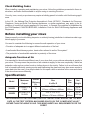
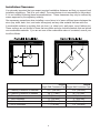
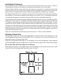
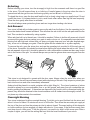
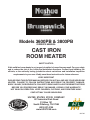
Models 3600PB & 3800PB
OWNER'S MANUAL
CAST IRON
ROOM HEATER
SAFETY NOTICE:
If this solid fuel room heater is not properly installed, a house fire may result. For your safety
and to reduce the risk of fire, follow the installation directions. Contact local building, fire
officials, or the authority having jurisdiction about restrictions and installation inspection
requirements in your area. Kindly save these instructions for future reference.
VERY IMPORTANT
PLEASE READ THIS ENTIRE MANUAL BEFORE YOU INSTALL AND USE YOUR NEW ROOM
HEATER. FAILURE TO FOLLOW INSTRUCTIONS MAY RESULT IN PROPERTY DAMAGE,
BODILY INJURY, OR EVEN DEATH. FAILURE TO READ AND FOLLOW THESE INSTRUCTIONS
BEFORE YOU PROCEED MAY RESULT IN DAMAGE, VOIDING YOUR WARRANTY!
STATES ST
OV
TED
I
N
USSC
COMPANY
E
U
HOT WHILE IN OPERATION. KEEP CHILDREN, CLOTHING, AND FURNITURE AWAY.
CONTACT MAY CAUSE SKIN BURNS.
UNITED STATES STOVE COMPANY
227 Industrial Park Road
P.O.Box 151
South Pittsburg, TN 37380
(423) 837-2100
www.USSTOVE.com
851795
Introduction
Congratulations on purchasing a U.S. Stove Product. When cared for properly, the high quality, finely crafted cast iron stove will offer many years of reliable performance. This instruction manual has
been developed to ensure optimum performance from your Nashua or Brunswick stove. It's very
important that you thoroughly read and understand all instructions before using your new stove.
Table of Contents
Stove Safety������������������������������������������������������������������������������������������������������������������������������������ 3
Before installing your stove���������������������������������������������������������������������������������������������������������� 4
Adequate Provision of Air............................................................................................................. 4
Specifications��������������������������������������������������������������������������������������������������������������������������������� 4
Installation��������������������������������������������������������������������������������������������������������������������������������������� 5
The Floor Protection.................................................................................................................... 5
Installation Clearances................................................................................................................. 6
Installation Clearances................................................................................................................. 7
Chimney Connection.................................................................................................................... 7
Chimney....................................................................................................................................... 8
Chimney Height........................................................................................................................... 8
Factory Built Chimney.................................................................................................................. 9
Masonry Chimney...................................................................................................................... 10
Combustible Wall Chimney Connector Pass-Throughs............................................................. 11
Operating Your Stove������������������������������������������������������������������������������������������������������������������� 12
Fuel............................................................................................................................................ 12
First operation of stove.............................................................................................................. 12
Air controls................................................................................................................................. 12
Refueling.................................................................................................................................... 13
Ash Removal.............................................................................................................................. 13
Overnight Burning...................................................................................................................... 13
Stove Maintenance����������������������������������������������������������������������������������������������������������������������� 14
Care of Glass............................................................................................................................. 14
Replacement of Glass................................................................................................................ 15
Replacing parts.......................................................................................................................... 15
Surface Finish............................................................................................................................ 15
Trouble Shooting�������������������������������������������������������������������������������������������������������������������������� 15
Fire Not Burning......................................................................................................................... 15
Glass Blackens.......................................................................................................................... 15
Smoke in Room......................................................................................................................... 16
Fire Burns to Quickly.................................................................................................................. 16
Fire Burns to Quickly.................................................................................................................. 16
Warranty Policy & Procedures���������������������������������������������������������������������������������������������������� 17
3600PB Parts Diagram & List������������������������������������������������������������������������������������������������������ 18
3800PB Parts Diagram & List������������������������������������������������������������������������������������������������������ 19
How to order repair parts ����������������������������������������������������������������������������������������������������������� 20
2
Stove Safety
IT IS YOUR OR THE INSTALLER’S RESPONSIBILITY TO READ ALL SAFETY PRECAUTIONS
AND FOLLOW THE PRESCRIBED DIRECTIONS.
When properly maintained and operated your stove should give you many years of service. However there are important safety aspects of these products that you need to be aware of when operating a wood stove.
1.ONLY USE SOLID WOOD FUEL. NEVER USE GASOLINE, GASOLINE-TYPE LANTERN FUEL,
KEROSENE, CHARCOAL LIGHTER FLUID, NAPHTHA, ENGINE OIL, OR SIMILAR LIQUIDS
TO START OR ‘FRESHEN UP’ A FIRE IN THIS STOVE. KEEP ALL SUCH LIQUIDS WELL
AWAY FROM THE STOVE WHILE IT IS IN USE. DO NOT BURN GARBAGE IN THE STOVE.
2.The burning of wood gives off gases which can be extremely dangerous. The stove is designed
that under normal operating circumstances these gases pass up the flue chimney system and
cannot escape into your home, however it is important that your flue system is properly installed
and that you check all joints regularly to ensure that there are no cracks or gaps, check the door
sealing rope and replace when damaged. We recommend a smoke alarm be fitted in rooms
where stoves are installed. Do not use stove in a room where negative pressure conditions may
occur, such as through the use of extraction fans unless an adequate air supply into the room is
ensured, as this may draw air through the stove and cause products of combustion to escape into
the room.
3.Creosote and soot may accumulate in your flue pipe and chimney. This may ignite, causing a
chimney fire. If you suspect a chimney fire evacuate people from the building, close down the
air controls on the stove and call the Fire Department. To prevent the accumulation of soot or
creosote, check flue and chimney regularly and clean as necessary. Good burning, hot stoves
will generally cause a lot less build-up than slow burning stoves. Likewise dry wood will cause
less build-up than wet wood. We recommend a fire extinguisher be available where stoves are
in operation. In the event of a chimney fire do not re-light the stove until it and the flue chimney
system have been thoroughly checked and repaired as necessary.
4.Stoves get extremely hot and should not be touched when lit. When young children are in the
area, we recommend the use of a suitable fire guard around the stove. Always wear protective
gloves when reloading stove.
5.Never over-fire your stove. If external parts of your stove are glowing red then the stove is overfiring and your draft settings should be reduced. Never interfere with the draft mechanisms or
adjust your air settings outside those limits set when the stove is manufactured. Never use a fan
to supply air to the stove or to extract air from it.
6.All users of the stove should be aware of the contents of this manual. Please leave this manual
where it is accessible to stove users and do not allow anyone to use the stove that is unfamiliar
with its correct operation.
7.Never use the stove if any parts are missing or damaged, only use genuine parts as replacements. Never modify your stove.
8.DO NOT INSTALL IN A MOBILE HOME.
We hope you have many years of warmth and comfort from your stove
but please do so safely.
3
Check Building Codes
When installing, operating and maintaining your stove, follow the guidelines presented in these instructions, and make them available to anyone using or servicing the stove.
Your city, town, county or province may require a building permit to install a solid fuel burning appliance.
In the U.S., the National Fire Protection Association’s Code, NFPA 211, Standards for Chimneys,
Fireplaces, Vents and Solid Fuel Burning Appliances, or similar regulations, may apply to the installation of a solid fuel burning appliance in your area. In Canada, the guideline is established by
the CSA Standard, CAN/CSA-B365-M93, Installation Code for Solid-Fuel-Burning Appliances and
Equipment.
Before installing your stove
Always consult your local building inspector or authority having jurisdiction to determine what regulations apply in your area.
You need to consider the following to ensure the safe operation of your stove.
• Provision of adequate air to support efficient combustion of the fuel.
• A well sealed flue/chimney system, herein after referred to as the “flue system”.
• The protection of combustible materials in proximity of the stove.
Adequate Provision of Air
It is essential for the safe and efficient use of your stove that you provide an adequate air supply to
your stove. This may mean the provision of an outside air supply to the room, especially if there are
extraction units such as cooker hoods or clothes dryers in the vicinity. Failure to do so will mean that
fuel is burned inefficiently causing smoke and blackening the glass and may also cause smoke to
come back into the room. As a simple check for this open a door or window in the room and check
if the stove burns more efficiently.
Specifications
Model
Maximum
Overall
Output
Efficiency
(%)
3600PB
37,000BTU or
11KW
73
3800PB
63,000BTU or
18.5KW
72
Size
HxWxD
Flue
Size
26⅝” x 20⅞” x 16½”
6"
675mm x 530mm x 420mm
33⅜” x 27⅝” x 23”
150mm
6"
860mm x 701mm x 583mm
150mm
Net
Weight
306 lb
(139 kg)
408 lb
(185 kg)
FOR PURPOSES OF THE TAX CREDIT, BOTH OF THESE STOVES EXCEED THE 75% MANDATE, AS THE TEST CRITERIA WAS BASED SOLELY ON THE “LOWER HEAT VALUE,”
RATHER THAN THE ABOVE SCALE. THIS MODEL MEETS ALL REQUIREMENTS FOR TAX
CREDIT.
4
Installation
Unpacking and preparing your stove for installation.
1.Remove your stove from the outer packaging and place on floor. Please inspect stove and check
that it is not damaged in any way. Never attempt to use a stove that has been damaged.
2.If you are installing the stove yourself, proceed as follows. However, if you are unsure about any
aspect of stove installation, please contact your dealer and he will discuss installation with you or
put you in touch with an experienced stove installer.
3.Open fire door. Remove and check the following contents.
• 4 stove legs
• Wooden handle and screws
• Ash pan
• Operating tool
• Handle holder
In the unlikely event that something is missing please contact your dealer immediately and we will
rectify the situation.
4.Gently lay the stove on its back. Remove screws from 4 corners of base and fit one of the legs to
each corner of the stove. Tighten bolt to ensure leg is secure to base of stove. When complete,
gently stand the stove upright.
5.Move the stove into position. Do not drag the stove as this may damage the legs, screws or base.
The Floor Protection
If the stove is to be installed on a combustible floor, it must be placed on a noncombustible hearth pad. In the USA, the
floor protector must extend 8” beyond
each side of the flue loading door and 16”
to the front. In Canada, the floor protector must extend 8“ (200mm) beyond each
side and the back of the appliance and
18“ (450mm) to the front. (See fig. 4)
In a rear vent installation the floor protection must also extend under the stovepipe a minimum of 2” (50mm) beyond
either side of the pipe.
5
Installation Clearances
It is extremely important that you respect required installation distances and that you respect local
installation regulations. This is for your safety! The manufacturer is not responsible for the product,
if it is not installed following these recommendations. These clearances may only be reduced by
means approved by the regulatory authority.
One necessary precautions when installing a wood stove is to leave sufficient space between the
stove (top, sides, back, front, and under stove pipes) and any other material that can catch fire.
A combustible surface is anything that can burn (i.e. sheet rock, wall paper, wood, fabrics etc.)
These surfaces are not limited to those that are visible and also include materials that are behind
non-combustible materials. If you are not sure of the combustible nature of a material, consult your
local fire officials.
3600PB
A – Chimney Connector to backwall
B – Chimney Connector to sidewall
C – Chimney Connector to cornerwall
D – Unit to backwall
E – Unit to sidewall
F – Unit to cornerwall
3800PB
Single Wall Connector Pipe Single Wall Connector Pipe
15.5” (394 mm)
21.5” (546 mm)
28” (711 mm)
29” (737 mm)
15” (381 mm)
21.5” (546 mm)
13” (330 mm)
17” (432 mm)
20” (508 mm)
20” (508 mm)
7” (178 mm)
11.5” (292 mm)
6
Installation Clearances
Only materials and items approved for solid fuel stoves should be used for your stove. Under no
circumstances should you use aluminum or galvanized steel pipes for your stove flue.
Always fit pipes with the narrow side down, this allow any creosote to run down the inside of the
pipe and not to come out and cause an unsightly mess and possible fire hazard. All joints in the flue
system should be sealed with fire cement and/or an appropriate fire resistant rope or gasket.
Pipe bends should be kept to a minimum and we do not recommend using more than 2 bends on
any installation. Flues must not pass through ceilings, floors, attics, roofs, or combustible walls without adequate and approved insulation being provided to protect combustible materials.
The chimney and flue provide a means of taking combusted fuel from the stove, as well as a draft to
enable the stove to work. It is essential that the flue system is kept in good condition and there are
no breaks or cracks allowing contact with any other combustible materials of the house. It is also
essential that the flue system is kept clean and seals are maintained to ensure the draft is not lost.
The open end of the flue system must be above the height of the apex of the building and any other
obstructions, such as trees, which are within 3 meters (10ft) of the flue system. Failure to do this will
affect the efficiency of the stove and may cause down drafts which will mean dangerous products of
combustion are emitted into room.
Under no circumstances should the flue pipe be less than 6” (125mm) internal diameter.
Chimney Connection
The chimney connector is a single walled pipe used to connect the stove to the chimney. For use
with the appliance the chimney connector MUST be 6” in diameter, with a minimum thickness of 24
gauge black steel or 26 gauge blued steel.
Aluminum and galvanized steel pipe is not acceptable for use with the appliance. These materials
cannot withstand the extreme temperatures of a wood fire and can give off toxic fumes when heated.
Do not use the connector pipe as a chimney.
Each chimney connector or stovepipe section must be installed to the stove flue collar and to each
other with the male (crimped) end toward the stove. See fig 5.
7
This prevents any amount of condensed or liquid creosote from running down the outside of the
pipe or the stove top. All joints, including the flue collar connection must be secured with three sheet
metal screws to ensure that the sections do not separate.
For the best performance the chimney connector should be as short and direct as possible, with no
more than two 90° elbows. The maximum horizontal run is 36” and a recommended total length of
stovepipe should not exceed 10 feet. Always slope horizontal runs upward ¼” per foot toward the
chimney.
No part of the chimney connector may pass through an attic or roof space, closet or other concealed space, or through a floor ceiling. All sections of the chimney connectors must be accessible
for cleaning. Where passage through a wall or partition of combustible construction is desired, the
installation must conform with NFPA 211 or CAN/CSA-B365, and is also addressed in this manual.
Chimney
DO NOT CONNECT THIS UNIT TO A CHIMNEY FLUE SERVING ANOTHER APPLIANCE. DO
NOT CONNECT TO ANY AIR DISTRIBUTION DUCT OR SYSTEM.
This room heater must be connected to a 6” factory built UL 103 HT chimney (ULC S629, in Canada) or a code-approved masonry chimney with a flue liner.
Chimney Height
A masonry chimney or a listed factory-build chimney must be the required height above the roof and
any other nearby obstructions. The chimney must be at least 3’ (90 cm) higher than the highest
point where it passes through the roof and at least 2’ (60 cm) higher than the highest part of the roof
or structure that is within 10’ (305 cm) of the chimney, measured horizontally.
8
Factory Built Chimney
When a metal prefabricated chimney is used, the manufacturer’s installation instructions must be
followed. You must also purchase (from the same manufacturer) and install the ceiling support
package or wall pass-through and “T” section package, firestops (where needed), insulation shield,
roof flashing, chimney cap, etc. Maintain proper clearance to the structure as recommended by the
manufacturer. The chimney must be the required height above the roof or other obstructions for
safety and proper draft operation.
9
Masonry Chimney
Ensure that a masonry chimney meets the minimum standards of the National Fire Protection Association (NFPA) by having it inspected by a professional. Make sure there are no cracks, loose
mortar or other signs of deterioration and blockage. Have the chimney cleaned before the stove is
installed and operated. When connecting the stove through a combustible wall to a masonry chimney, special methods are needed.
10
Combustible Wall Chimney Connector Pass-Throughs
Method A. 12” (304.8 mm) Clearance to Combustible Wall Member:
Using a minimum thickness 3.5” (89 mm) brick and a 5/8” (15.9 mm)
minimum wall thickness clay liner, construct a wall pass-through.
The clay liner must conform to ASTM C315 (Standard Specification for Clay Fire Linings) or its equivalent. Keep a minimum of
12” (304.8 mm) of brick masonry between the clay liner and wall
combustibles. The clay liner shall run from the brick masonry outer
surface to the inner surface of the chimney flue liner but not past
the inner surface. Firmly grout or cement the clay liner in place to
the chimney flue liner.
Method B. 9” (228.6 mm) Clearance to Combustible Wall Member:
Using a 6” (152.4 mm) inside diameter, listed, factory-built SolidPak chimney section with insulation of 1” (25.4 mm) or more, build
a wall pass-through with a minimum 9” (228.6 mm) air space between the outer wall of the chimney length and wall combustibles.
Use sheet metal supports fastened securely to wall surfaces on all
sides, to maintain the 9” (228.6 mm) air space. When fastening
supports to chimney length, do not penetrate the chimney liner (the
inside wall of the Solid-Pak chimney). The inner end of the SolidPak chimney section shall be flush with the inside of the masonry
chimney flue, and sealed with a non-water soluble refractory cement. Use this cement to also seal to the brick masonry penetration.
Method C. 6” (152.4 mm) Clearance to Combustible Wall Member:
Starting with a minimum 24 gage (.024” [.61 mm]) 6” (152.4 mm)
metal chimney connector, and a minimum 24 gage ventilated wall
thimble which has two air channels of 1” (25.4 mm) each, construct
a wall pass-through. There shall be a minimum 6” (152.4) mm separation area containing fiberglass insulation, from the outer surface
of the wall thimble to wall combustibles. Support the wall thimble,
and cover its opening with a 24-gage minimum sheet metal support. Maintain the 6” (152.4 mm) space. There should also be a
support sized to fit and hold the metal chimney connector. See that
the supports are fastened securely to wall surfaces on all sides.
Make sure fasteners used to secure the metal chimney connector
do not penetrate chimney flue liner.
Method D. 2” (50.8 mm) Clearance to Combustible Wall Member: Start with a solid-pak listed factory built chimney section at
least 12” (304 mm) long, with insulation of 1” (25.4 mm) or more,
and an inside diameter of 8” (2 inches [51 mm] larger than the 6”
[152.4 mm] chimney connector). Use this as a pass-through for
a minimum 24-gauge single wall steel chimney connector. Keep
solid-pak section concentric with and spaced 1” (25.4 mm) off the
chimney connector by way of sheet metal support plates at both
ends of chimney section. Cover opening with and support chimney
section on both sides with 24 gage minimum sheet metal supports.
See that the supports are fastened securely to wall surfaces on all
sides. Make sure fasteners used to secure chimney flue line.
NOTES:
1. Connectors to a masonry chimney, excepting method B, shall extend in one continuous section through the wall
pass-through system and the chimney wall, to but not past the inner flue liner face.
2. A chimney connector shall not pass through an attic or roof space, closet or similar concealed space, or a floor, or
ceiling.
11
Operating Your Stove
Do not use a grate, andiron or other fuel support method. Build fire directly on the hearth.
Only open door to fuel/refuel the stove. Excess air can cause the stove to over fire. Do not over
fire, if chimney or stove is glowing red you are over firing.
Do not build the fire too close to the glass. Do not abuse the glass doors. Do not strike or slam
shut the door.
DO NOT USE CHEMICALS OR FLUIDS TO START THE FIRE.
Fuel
Your stove is designed to burn solid wood fuel only; it is not designed to burn,
• Paper or cardboard, other than small amounts used to light stove.
• Treated or painted wood
• Synthetic fuel or logs that are not approved for solid fuel stoves
• Household rubbish
• Liquid fuels
• Plastics
Burning these or other products for which the stove was not designed may damage the stove and
cause a fire hazard or release toxic fumes
Fuel should be stored in a dry place; wood should be dried for at least 1 year. Do not store fuel within
the installation clearances or within the space required for charging and ash removal. Wet wood
may cause serious creosote, which may damage your flue system and even your stove. Therefore
the use of wet wood is strongly discouraged.
First operation of stove
You should begin using your stove by lighting small fires which get progressively bigger. We recommend a series of about five small fires before you put the stove into full service. Allow the stove to
fully cool between each of these fires. There may be some smell and a small amount of smoke from
the stove during the initial operations. This is perfectly normal and is merely the curing of the stove
paint. Opening a window or door to provide additional ventilation will help alleviate this.
Air controls
Your stove needs air to burn the fuel. This air is supplied through the spin valve at the base of the
door and through the slots over the glass.
Primary air, as the name suggests, is used for the initial burning of the fuel. Secondary air is used
for secondary combustion, which makes the stove more efficient, reduces the emissions and is also
used to keep the stove glass clean. Wood burns better with the air over the fire bed and when burning a lot of wood, you should use the secondary air supply more.
The settings of both of these air controls very much depends on draft and local conditions and after
a few fires, you should have a good idea of the best settings for your stove. The air controls should
be fully opened when lighting the fire. Once the fire is established, the controls may be adjusted as
required. Reducing the air intake will cause the stove to burn slower. This may cause some blackening of the stove glass, but this should burn off once the stove is burning brightly again.
12
Refueling
Before refueling your stove, turn the air supply to high for a few moments until there is a good fire
in the stove. This will ensure there is no build-up of harmful gases in the stove when the door is
opened and will also get the new fuel burning quickly and not allow it to kill the fire.
To reload the stove, open the door and feed the fuel in slowly using tongs or a small shovel. Do not
overfill the stove. It is always better to put in small loads often rather than big fills less frequently.
Close the door gently after stove is reloaded.
You should always wear protective gloves and use tongs when tending a hot stove.
Ash Removal
Your stove is fitted with a shaker grate to remove the ash from the firebox. Use the operating tool to
move the shaker knob forward and back. This will allow the ash to fall into the ash pan under the fire
bed. This can also be achieved by using a poker.
When ash has built up in the ash pan, it should be emptied. Failure to do this will cause ash to build
up around the grate and may cause your grate to warp or burn out. It is especially important when
burning fuel with high ash content that you keep your grate clear and your ash pan emptied regularly, so as not to damage your grate. Clear the grate with the shaker bar or a poker regularly.
To remove the ash, open the stove door and use the operating tool provided to lift the ash pan out
of the stove. If possible, this should be done before lighting the stove when the ash is cold. Even if
the ash appears to be cold, it should be placed in a non-combustible container as there may be hot
ash in the center of the pile. You should always were protective gloves when removing ash from the
stove.
This stove is not designed to operate with the door open. Always close the stove door when you
have taken out the ash tray and leave closed while disposing of the ash. Only reopen to put ash pan
back into the stove and close immediately afterwards.
Ashes should be placed in a metal container with a tight fitting lid. The closed container of ashes
should be placed on a noncombustible floor or on the ground, well away from all combustible materials, pending final disposal. If the ashes are disposed of by burial in soil or otherwise locally dispersed, they should be retained in the closed container until all cinders have thoroughly cooled. Do
not place any other waste in the container.
Overnight Burning
Your stove is designed to allow overnight burning. To do this, put a good fuel bed into the stove and
allow it to burn for about 15 minutes so as not to kill the fire. Then close the secondary air supply at
the top of the door and turn the primary air inlet to almost closed. The exact setting of this depends
on local conditions, but we suggest you begin with about a ½ turn open. If the fire burns away, then
next time close it a little more. If the fire goes out, you need to try with it a little more open. After a
couple of nights, you will find the setting that best suits the local conditions of your stove.
13
When you return to your stove, fully open both air controls until you have a good fire and then set
to normal operating levels. Do not add fuel until the fire bed is hot and red. Then add a little for the
first time and allow that to ignite before adding more. During overnight burning, the stove glass will
blacken, but when a hot fire is established again this should burn off.
Stove Maintenance
CHECK STOVE REGULARLY
Creosote – Formation and Need for Removal – When wood is burned slowly, it produces tar and
other organic vapors, which combine with expelled moisture to form creosote. The creosote vapors
condense in the relatively cool chimney flue of a slow-burning fire. As a result, creosote residue
accumulates on the flue lining. When ignited, this creosote makes an extremely hot fire. The chimney and chimney connector should be inspected at least once every two months during the heating
season to determine if a creosote buildup has occurred. If creosote has accumulated, it should be
removed to reduce the risk of a chimney fire.
Initially, we recommend you check your flue system at least once per month. After the first few
months you will notice a pattern of soot and creosote build up and you can then determine an inspection interval for checking soot and creosote build up that is suitable for your stove installation.
Other checks, as listed below, should be carried out at least twice per year. If you notice anything
wrong at any time it should be repaired immediately. Never use a stove that is in any way damaged
or has a damaged flue.
1.Check your flue system for build up of soot or creosote and for signs of damage to joints. To check
flue outlet remove top of baffle by lifting and pulling out at end. Use a flashlight to check flue outlet. Clean and repair as necessary. Always replace top baffle before relighting stove.
2.Check that glass is not cracked or chipped and that sealing rope is in good condition. Replace as
necessary.
3.When the room is dark, use a strong flashlight to check the sealing of the stove at the edge and
corners for leaks. Any leaks or cracks found should be repaired with fire cement or damaged
parts should be replaced with genuine spare parts.
4.Check that stove door is tight and well sealed when closed. Place a strip of paper into the stove
and close the door, try to pull out paper. You should feel some resistance to your pull, check
several points around the door. If it pulls out too easily, replace the rope and seal in place with a
suitable high temperature sealant.
Care of Glass
At times, especially when the air controls are turned to low settings or when damp wood is used, the
stove glass will blacken. This is caused by fuel that is not completely burnt, but the build-up on the
inside of the glass will normally burn off when a good hot fire is established in the stove.
There may be times however when you need to clean the glass. To do this, use a soft cloth and a
non-abrasive glass cleaner. Only ever clean the glass when the stove is cold. When loading fuel
into the stove, always make sure it is not protruding out through the door opening, as this may break
the glass when you close the door. This is especially relevant when loading logs. Always close the
door gently.
Do not operate with broken or cracked glass. If the glass does crack when the stove is lit, let the fire
die out. Do not open the door until the stove has fully cooled. Replace the glass only with the specified replacement part before re-using the stove.
14
Replacement of Glass
1.Remove the door from the stove and place on a flat surface.
2.Carefully remove all of the glass clips from the inside of the door.
3.Gently remove the glass panel and gasket.
4.Using a wire brush, remove all remaining debris from the glass area.
5.Apply a small bead of gasket/stove cement and the new gasket. Do not overlap the ends of the
gasket rope.
6.Center the new glass panel over the gasket and reinstall the glass clips.
7. It may be necessary to retighten the glass clips after the stove has be burned and the gasket has
been seated.
Important:
1.It is extremely important to tighten the glass clips slowly and in an alternating pattern.
2.Always wear protective gloves when you handle glass with sharp edges.
Replacing parts
Always use genuine replacement parts. Only ever make replacements when the stove is cold.
Surface Finish
The stove should only be cleaned using a damp cloth. Some cleaning products may leave stains on
the stove surface. Never use abrasive cloths as these may scratch the surface. Painted stoves can
be re-painted by using a good quality, high temperature stove paint. When re-painting, make sure
there is plenty of ventilation and follow the manufacturer’s instructions. Allow the paint to fully dry
before lighting the stove and allow extra ventilation for the first couple of fires as some fumes may
emit from the stove as the paint cures.
Trouble Shooting
Fire Not Burning
A stove not burning is generally caused by either a shortage of air and/or incorrect or damp fuel. If
fuel is not the problem check:
• That the air controls are opened.
• There is no blockage in the flue system.
• That the open end of the flue is above the height of any nearby obstructions.
• That there is a sufficient air supply into the room and that this supply is not being taken by an
extractor fan.
Glass Blackens
Glass usually blackens when:
• The fuel is not being burned efficiently because of starvation of air.
• Bad quality or damp fuel is being used.
• Balance between primary and secondary air is incorrect.
Try to introduce more air into the stove, especially through the secondary air control on the top of the
stove door as this air flows down over the glass to help burn off the creosote. For optimum efficiency
always use a good quality wood.
15
Smoke in Room
If the stove is properly installed it should not emit any smoke into your room. Should this happen,
Check that your room is not air tight. This can easily be checked by opening a door or window. If the
smoking stops you need to provide an additional air supply into the room. If this is not the problem,
check if your chimney is blocked or obstructed and that you are not getting a down draft caused by
the location of the open end of the flue pipe or chimney.
If the problem persists contact your dealer and ask him to get your chimney and stove installation
checked.
Fire Burns too Quickly
This is usually caused by too much draft or air.
• Firstly try reducing the air supply to the stove by closing down your air controls, if this fails then
you may have damage to the sealing.
• Check the condition of the door sealing rope and the joints within the stove.
If neither of these solve the problem you may have too much draft on your chimney and you may
need to fit a damper valve into your flue system. You should not install a flue damper without consulting a specialist. Never install a damper that can completely block your flue or chimney. Contact
your dealer to discuss this.
Fire Burns too Quickly
Chimney fires occur when soot and creosote that have built up in the flue system ignite. If the stove
is operated properly and the flue checked and cleaned regularly then chimney fires should not occur. These fires can be very dangerous and must be avoided. Try to maintain good, hot fires in the
stove whenever possible and at least once in every firing open the air controls and allow the stove to
burn on full for a short while until the entire fire bed is glowing red. Check your flue system regularly
for build-up of soot and creosote and clean as necessary.
Chimney fires can be detected by sparks coming from the top of the chimney, a roaring sound coming from the area of the stove or chimney or vibration in the stove or chimney.
In the event of a chimney fire, close the air controls, evacuate the building and call the fire department. Do not relight the stove after a chimney fire until the stove and flue have been checked and
any necessary repairs have been carried out.
16
Warranty Policy & Procedures
U.S. Stove offers the original retail purchaser of the Solid Fuel burning products a limited 5-year warranty.
The following outlines the U. S. Stove's Warranty programs.
U. S. Stove Limited Warranty
This warranty applies to the original retail purchaser only. U. S. Stove warrants that this stove will be free of defects in
material and workmanship for a period of five years from the date of purchase. U. S. Stove will repair or replace (parts
and labor) at its option, any stove or part thereof found to be defective.
Warranty Defined
Description
Parts
Labor
Firebox (welding only )
5 Years
1 year
Handle assembly
5 Years
Not Included
Ash pan
5 Years
1 year
Cast iron parts
5 Years
1 year
Ceramic glass (thermal breakage only )
1 year
Not Included
Paint, fire bricks
1 year
Not Included
You must arrange to deliver or ship the stove or part to an authorized U. S. Stove dealer at your own expense and arrange for pickup or delivery of the same after the repairs have been made. If, upon inspection, any damage is found
to be the fault of the manufacturer, the repair or replacement will be made. This warranty does not include expenses
incurred from travel time or loss of service. This warranty is not transferable and is extended only to, and is solely for the
benefit of, the original retail purchaser of the stove. Please keep your dated sales receipt as proof of purchase.
Exclusions and Limitations
This warranty does not cover the following:
1. Repair or replacement of parts, which are subject to normal wear and tear during the warranty period or to parts that
may require replacement in connection with normal maintenance. These parts include paint, gaskets, burn plates,
baffles, fire grates or glass (glass is only warranted against thermal breakage).
2. Damage due to incorrect installations not in conformance with the manufacturer’s installation instructions or local and
national regulations. It is the responsibility of the installer to ensure that the unit is installed and operating correctly
at the time of installation.
3. Damage caused by over-firing, which causes any part of the appliance to glow red, as defined in the operation
manual. Over-firing can be identified by warped plates, rust colored cast iron, paint pigment that has turned dusty
white, or bubbling, cracking and discoloration of the enamel finish.
4. Damage caused by unauthorized modification, use, or repair.
5. Damage made while the stove is in transit.
6. Products for which the manufacturer provides a specific warranty.
7. Travel time or any other expenses are not covered under warranty.
8. At no time will U. S. Stove be liable for any consequential damage which exceeds the purchase price of the unit. All
warranties, implied warranties of merchantability or other, are limited in duration to the length of this written warranty.
No other warranty, including oral, is enforceable.
NOTICE - This warranty is void if installation or service is performed by someone other than a qualified installer, service
agency or if installation is not in conformity with installation instructions or local fire and building regulations. All warranty
claims must be submitted through the authorized U. S. Stove dealer from whom the product was originally purchased.
You may have other rights and obligations which vary from State to State. If you have a problem which proves difficult to
resolve, feel free to contact United States Stove Company at 800.750.2723 and ask for Customer Service – Technical.
Or you may find your answers on our website: www.usstove.com.
17
3600PB Parts Diagram & List
1 11
2 34
5 6 7
17
18
19
20
21
8 9 10
25
24
12 13 14 15
22
23
38
37
36
39
26
16
27
41 33
32
34
28
29
30
35
31
40
KEY
PART #
DESCRIPTION
1
2
3
4
5
6
7
8
9
10
11
12
13
14
15
16
17
18
19
20
21
40517
40518
40519
891689
40520
40521
40522
40523
40524
40525
891690
40526
891691
891692
40527
891693
891694
40528
40529
40530
40531
Hob (HF517U-1)
Top Frame Casting (HF517U-2)
Secondary Air Deflector Plate (HF517U-3)
Small Cover Plate (HF517U-4)
Top Baffle (HF517U-5)
Front (HF517U-6)
Left/Right Hand Side (HF517U-7)
Back Cover, Fire Fence (HF517U-8)
Fire Fence (HF517U-9)
Slid Knob (HF517U-10)
Secondary Air Cover Plate (HF517U-11)
Fire Door (HF517U-12)
Door Handle Rod (HF517U-13)
Door Handle (HF517U-14)
Spin Valve (HF517U-15)
Door Latch Plate (HF517U-16)
Back Plate, Ornamental (HF517U-17)
Back Cover (HF517U-18)
Cover, Back Air Inlet (HF517U-19)
Lock-tight Piece (HF517U-20)
Back (HF517U-21)
QTY.
KEY
PART #
DESCRIPTION
1
1
1
1
1
1
2
1
1
1
1
1
1
1
1
1
1
1
1
1
1
22
23
24
25
26
27
28
29
30
31
32
33
34
35
36
37
38
39
40
41
891695
891696
891697
891698
40532
40533
40534
40535
40536
40537
891699
891701
40538
891708
891709
891711
891712
891713
891714
891715
Slide Plate Holding Frame (HF517U-22)
Slide Plate (HF517U-23)
Glass Holding Frame (HF517U-24)
Glass (HF517U-25)
Grate (HF517U-26)
Grate Frame (HF517U-27)
Base (HF517U-28)
Ashtray (HF517U-29)
Leg (HF517U-30)
Operating Tool (HF517U-31)
Ashpan (HF517U-32)
Handle Pays (HF517U-33)
Ash Door (HF517U-34)
Operating Rod (HF517U-35)
Left Side Firebrick (HF517U-36)
Right Side Firebrick (HF517U-37)
Back Side Firebrick (HF517U-38)
Bottom Side Firebrick (HF517U-39)
Heat Insulation Plate (HF517U-40)
Sealing Tape (HF517U-41)
18
QTY.
1
1
4
1
1
1
1
1
4
1
1
1
1
1
1
1
1
1
1
1
3800PB Parts Diagram & List
1
22
55
33
66
77
88
41
46
40
45
10
10
44
14
13
38
43
39
44
11
12
12
13
orse
99
lame
25
28
43
48
37
42
36
35
40
27
32 26
33
38 34
39
22
25
orse
lam
e
42
47
141515
16
16
17
18
31
3632
37
20
21
30
35
29
34
28
33
KEY
PART #
DESCRIPTION
1
2
3
4
5
6
7
8
9
10
11
12
13
14
15
16
17
18
19
20
21
22
40539
40540
891716
891717
891718
40541
40542
40543
891719
40544
891720
891721
40546
40547
40548
891722
891723
40549
40550
40551
891724
891725
Hob (HF717U-1)
Top Frame Casting (HF717U-2)
Sealing Tape (HF717U-3)
Slide Plate (HF717U-4)
Slide Plate Holding Frame (HF717U-5)
Back Slide Plate (HF717U-6)
Front (HF717U-7)
Fire Fence (HF717U-8)
Door Hinge (HF717U-9)
Left Hand Side (HF717U-10)
Glass Holding Frame (HF717U-12)
Glass (HF717U-13)
Slide Knob (HF717U-14)
Grate Frame (HF717U-15))
Grate (HF717U-16)
Door Handle Rod (HF717U-17)
Ashpan (HF717U-18)
Spin Valve (HF717U-19)
Operating Tool (HF717U-20)
Ash Door (HF717U-21)
Handle Pays (HF717U-22)
Door Latch Plate (HF717U-25)
21
22
18
19
19
20
23
26
24
27
QTY.
KEY
PART #
DESCRIPTION
1
1
1
1
1
1
1
1
1
1
4
1
1
1
1
1
1
1
1
1
23
24
25
26
27
28
29
30
31
32
33
34
35
36
37
38
39
40
41
42
43
891726
891727
40552
40553
40554
40555
40556
891728
891729
891730
891731
891732
40557
891733
40558
40559
891734
891735
40560
891736
891737
Door Handle (HF717U-26)
Door Catch (HF717U-27)
Fire Door (HF717U-28)
Fire Fence Bracket (HF717U-31)
Door Catch Sealing Plate (HF717U-32)
Leg (HF717U-33)
Base (HF717U-34)
Left Side Firebrick (HF717U-35)
Right Side Firebrick (HF717U-36)
Back Side Firebrick (HF717U-37)
Bottom Side Firebrick (HF717U-38)
Front Side Firebrick (HF717U-39)
Right Hand Side (HF717U-40)
Secondary Air Deflector Plate (HF717U-41)
Secondary Air Deflector Plate (HF717U-42)
Flue Blanking Plate (HF717U-43)
Boiler (HF717U-44)
Back Ornamental Plate (HF717U-45)
Hob Blanking Plate (HF717U-46)
Short Tube (HF717-47)
Separate Hot Fiber (HF717U-48)
1
19
QTY.
1
1
1
2
1
4
1
1
1
1
1
1
1
1
1
1
1
1
1
1
2
How to order repair parts
THIS MANUAL WILL HELP YOU OBTAIN EFFICIENT, DEPENDABLE
SERVICE FROM YOUR FURNACE, AND ENABLE YOU TO ORDER
REPAIR PARTS CORRECTLY.
KEEP THIS MANUAL IN A SAFE PLACE FOR FUTURE REFERENCE.
WHEN WRITING, ALWAYS GIVE THE FULL MODEL NUMBER WHICH
IS ON THE NAMEPLATE ATTACHED TO THE HEATER.
WHEN ORDERING REPAIR PARTS, ALWAYS GIVE THE FOLLOWING
INFORMATION AS SHOWN IN THIS LIST:
1. THE PART NUMBER
2. THE PART DESCRIPTION
3. THE MODEL NUMBER:
3600PB
3800PB
STATES ST
OV
TED
I
N
USSC
COMPANY
E
U
4. THE SERIAL NUMBER:____________________
United States Stove Company
227 Industrial Park Road
P.O. Box 151
South Pittsburg, TN 37380
(800) 750-2723
WWW.USSTOVE.COM
20