1
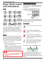
Captiv8-20
Intruder alarm system
Operating instructions
Introduction
The purpose of this booklet is to describe how to operate Captiv8-20 intruder alarm system. Some of the
features described in this guide may not be applicable to your installation and should be ignored. The engineer
from the alarm company should have completed the System Information in this booklet which gives information
specific to your installation. You will need to refer to this as you read these instructions in order to check if
certain features have been used. If in any doubt consult your alarm company.
6
M
N
O
B
8
0
T
U
V
9
W
X
Y
Z
d
J
K
L
Lt
5
ity
&
Fi
re
A
PA
C
OMIT
ENTER
In
te
RESET
D
E
F
Alert
ec
7
P
Q
R
S
3
Power
tS
G
H
I
A
B
C
en
4
2
llig
1
ur
Thursday
06-May
09:37:00
To SET or UNSET
Enter Code
Installer:
?
?
?
?
Day tel:
To PART SET
Enter Code and
Select:
A
or
B
or
C
24Hr Call out:
ARC No:
4201-630 issue 1_2/04
Alarm company (Installer) name: __________________________________________
Telephone number: _____________________________________________________
Account number: _______________________________________________________
Installation date: _______________________________________________________
1
Operating instructions
Proximity tag (keyfob)
Keys, Entry codes
and indications
If your keypad has an integral proximity tag reader
you can Set, Part Set, if programmed, and Unset the
intruder system.
A Keypad having a proximity tag reader can be
recognised by a depression on the keypad flap.
Keys
2
1
4
G
H
I
7
P
Q
R
S
5
J
K
L
8
0
T
U
V
3
6
M
N
O
9
W
X
Y
Z
OMIT
Keypad
with proximity tag reader
D
E
F
SYSTEM SET
A
Offer the proximity
tag to the Keypad
and withdraw
B
Proximity tag
(Keyfob)
If you should need further proximity tags you should
consult your installer, up to 16 maximum proximity
tags can operate your system.
C
Indications
ENTER
The Power indicator will be lit all the time.
ur
ity
&
Fi
re
Power
te
In
Codes
llig
en
tS
ec
You operate your intruder alarm system by means of
a keypad. On the right of a key is a label which
describes the secondary function of each key. The
keys will perform their secondary function when text
entry is required, for example to describe users and
zones.
Lt
d
RESET
A
B
C
Alert
The Alert indicator will give a flashing
indication of unacknowledged fault(s) in the
system.
The Alert indicator will give a steady On
indication of fault(s) acknowledgement. All
Alert existing faults must be acknowledged before
a system can be set.
Before you can do anything with Captiv8-20 you will
need to key in a code using one of the keypads. There
are two types of entry code, which permit different
levels of control over the system. Check the System
The Alert indicator will switch Off when the
Information to see which codes have been enabled.
system is Set. If the indicator is Off during
The different types of codes are:
Alert Unset condition this means there are no
faults present in the system.
ÿ Normal - this code allows the system to be set,
unset, and reset after an alarm.
ÿ Manager - this code has the same functions as a Standby display of an Unset system with no faults:
Day
normal user code, but in addition the manager
code can add or delete all other codes, test the
system, view the event log, set the time and date,
omit 24Hr zones, and set the chime function.
"
Date Month
Thursday
06-May
09:37:00
Time: hours, minutes and seconds
The display and keypad have backlight(s) which are
The Codes may be either 4 digit set to illuminate for a short duration when a key is
or 6 digit in length, see the System
pressed or when the system becomes active. Your
installer may have configured the backlight to be On at
information.
all times.
2
Captiv8-20
Full Set using a User code or tag
Setting the
system
Key in a normal user code ? ? ? ? at the keypad
nearest the final exit door. Alternatively present a user
proximity tag to a keypad having a proximity tag
reader.
Before fully setting the system
First, check that the premises are physically secure,
check to ensure all windows are shut, and all external
doors locked. When the premises are completely
vacated you should fully set the system.
If Part Set programs B or C are enabled then the
display will ask you to select how you would like your
system set.
System Set
Select A B or C
"
Press the A
key to select Program A to fully
set the system. If no attempt is made to press the A
key the system will automatically select Full Set
Program A.
If your system is configured for
police response then it is recommended
that you use the proximity tag to set the
system.
ec
ur
ity
&
Fi
re
Lt
d
The exit period will start and the inside sounder will
produce the exit sound - a pip-pip-pip sound.
Prevention of setting
You must now vacate the premises by the exit route
A fault condition such as mains failure or fuse failure
described in the System information. The length of
will cause the Alert indicator to flash. A fault Alert must time that you have to vacate the premises depends on
be acknowledged before the system can be set. When the exit mode that has been programmed. Check your
all the faults have been acknowledged the Alert
System Information to find out the exit mode of
indicator will change to steady On indication.
program A.
** SYSTEM SET**
In
te
llig
en
tS
To acknowledge fault Alert:
Key in your user code ? ? ? ? to display the first
fault. Acknowledge the fault by pressing ENTER
button. Repeat the procedure to acknowledge other
faults. The system can now be set.
3
Operating instructions
Full Set using the Manager code
Part-Set the System
The system can be fully set using the manager code, A part-set allows detection zones in part of the
the procedures are slightly different to that when using protected premises to be set (turned on), while those
a normal user code.
in other areas are not set. In a domestic installation it
is usual for a part-set to be programmed for use at
night time. This would allow the detection zones
Key in the manager code ? ? ? ? at the keypad
around the perimeter of the house (doors, windows,
nearest the final exit door.
etc), and all downstairs detectors to be enabled, while
detectors in the bedrooms and on the stairs and
1) Set system?
landing are disabled.
Ent to Set
Captiv8-20 has 2 different part-set programs called B
and C. Check your System Information to see if these
programs have been enabled. If they have not been
enabled then you will not be able to use them.
Press ENTER
If Part Set programs B or C are enabled then the
display will ask you to select how you would like your
system set.
If a part-set has been enabled you can part-set your
system by doing the following: Enter your code at a
keypad ? ? ? ? or alternatively present the
proximity tag to the keypad. The display will ask you
to select how you would like your system set.
System Set
Select A B or C
re
Lt
d
Press the A
key to select Program A to fully
set the system. If no attempt is made to press the A
key the system will automatically select Full Set
Program A.
ec
ur
ity
&
Fi
System Set
Select A B or C
In
te
llig
en
tS
The exit period will start and the inside sounder will
produce the exit sound - a pip-pip-pip sound.
You must now vacate the premises by the exit route
described in the System information. The length of
time that you have to vacate the premises depends on
the exit mode that has been programmed. Check your
System Information to find out the exit mode of
program A.
**SYSTEM SET**
4
Within 5 seconds of entering your code you must
press either the B
or C
key to select
one of the part-set programs. The display will
acknowledge this by displaying name of the program
being set.
The bottom line on the display may have been edited
during installation to read a different message, for
example it may read NIGHT TIME. Leave the
protected area by the exit route appropriate for that
part-set.
Captiv8-20
Performing a Quick-Set
Omitting zones during setting
Once you have selected the program to set, A, B or C,
it is possible to override the programmed exit time by
pressing the C key. This will give 5 seconds to vacate
the protected area.
It is possible to omit one or more detection zones
when you set the system. The omitted zones will not
be able to cause an alarm when the system has set.
This facility may be useful if one of the detection zone
has become faulty and keeps producing false alarms
Cancelling the Exit procedure
"
If you key in your code, and then immediately decide
not to set the system, you can cancel the exit
procedure.
The system will only Omit
Zones for the duration of the SET period,
the omitted zones are automatically
reinstated once the system has been
UNSET.
Key in your code ? ? ? ? to cancel the exit
procedure or alternatively present a proximity tag to
a keypad.
Because omitting a detection zone degrades the
security provided by your alarm system, your engineer
may have programmed only a limited number of zones
to be omittable. Check your System Information to see
which zones, if any, can be omitted.
The inside sounder will stop, the keypad will display
the 'System Unset' message for a few seconds and
then display the time and date.
Lt
d
X SYSTEM UNSET X
In
te
llig
en
tS
ec
ur
ity
&
Fi
re
Zones can be omitted by pressing the OMIT key
during the exit period.
01:FRONT DOOR
Omit Zone: NO
The exit sound will stop, and the keypad will display
the first zone from a list of zones that can be omitted.
Use the A
and B
keys to step through
the zones until the zone you want to omit is displayed.
Now press the OMIT key to change the NO to
YES.
Press the ENTER key.
The zone(s) will be omitted and the exit period will
start again. You can omit as many zones as you want
using this procedure.
5
Operating instructions
Unsetting the
system
"
If your system is configured for
police response then it is recommended
that you use the proximity tag to Unset the
system.
tS
ec
Lt
re
Fi
&
ity
ur
Entering the premises by the designated entry route
will cause the entry period to start. The inside sounder
will emit a slow beep-beep-beep sound. You must
now key in your code ? ? ? ? or alternatively
present a proximity tag at the nearest available
keypad to cancel the entry period. The length of time
that you have is called the entry time; check your
System Information for entry duration. During the last
10 seconds of the entry period the entry tone will raise
in pitch to inform you of the urgency to enter your
code or present the proximity tag to the nearest
keypad.
d
Unsetting the System
In
te
llig
en
If you enter your code within the entry period the
inside sounder will stop, the keypad will display the
‘System Unset’ message for few seconds and then
display the time and date.
X SYSTEM UNSET X
Thursday 06-May
03:30:00
6
Captiv8-20
Silence Alarm and
Reset system
To reset by Engineer Code
To silence an Alarm
If the engineer has programmed the system for
engineer reset, check the System information, it may
need to be reset by an engineer code. First, try
entering your code; if the keypad displays:
If an alarm occurs whilst you are in or near to the
premises the alarm can always be silenced by
entering your code ? ? ? ? or alternatively present
a proximity tag. If the system was set it will be unset
at the same time. If the alarm occurs while you are
away from the premises the outside and inside
sounders will automatically stop after the bell time
programmed by the engineer, see your System
Information for the bell time.
Engineer Reset
Required
You may need to call out the engineer to reset the
system. Before you do this, check the System
information to see if either the Remote PC Reset or
Anti-code Reset options have been enabled, if so then
go to the respective section in this booklet to reset the
system.
When you enter your code after an alarm, the keypad
will display the cause of the alarm.
INTRUDER
BACK DOOR
ec
ur
ity
&
Fi
re
Lt
d
Once the reason for activation has been determined
the Engineer will reset the system by entering his
The second line shows additional information, such as
code ? ? ? ? .
the zone which caused the alarm. The system will
now need to be reset as described in the next section.
After the system has been reset it may enter a fault
lockout, see page 8 .
llig
en
tS
To reset after an Alarm
In
te
After an alarm the system will need to be reset by
entering a code ? ? ? ? . The display will alternate
between the alarm cause and a prompt to enter a
reset code.
Reset required
Enter Your Code
If this prompt is displayed you can reset the system
using your own code. Key in your code ? ? ? ? .
After the system has been reset it may enter a fault
lockout, see fault lockout see page 8.
To reset by Anti Code
If Anti-code reset has been enabled the keypad will
display the 4-digit Quote code.
Quote Code nnnn
Enter Anti code
Make a note of this number nnnn (it is different each
time you use this facility) and telephone your Alarm
Receiving Centre (ARC). You may need to give
details of the alarm and quote a password. You will
also need to quote the 4 digit number nnnn. The
Alarm Receiving Centre will quote a 6 digit number
called an anti-code.
Key in the anti-code ? ? ? ? ? ? to reset the
system. The display will either clear and the system
will revert to unset mode, or it will display the number
of faults which still exist - this is a fault lockout see
page 8.
7
Operating instructions
To reset by Remote PC reset
Fault Lockout
Your engineer will have given you instructions on how
to request a Remote PC reset.
System Unset by
Richard
After resetting the system the keypad display will
either display the ‘System Reset’ message, or it will
show a count of the faults which still exist. This is
called fault lockout.
When the Remote PC reset is received by your
system, the keypad will display the ‘System Reset’
message for a few seconds. It will then either revert to
the time and date display, or display the number of
faults which still exist - this is a fault lockout.
Faults: 1
ENTER to View
These faults must be cleared before the system can
return to Unset mode.
To see a list of the faults press the ENTER key. The
keypad will display each fault for 5 seconds. When all
of the faults have been displayed it will again display a
count of the faults. It will often be necessary to call out
the engineer in order to clear these faults.
In
te
llig
en
tS
ec
ur
ity
&
Fi
re
Lt
d
If you can, clear the faults until the display shows no
faults.
8
Captiv8-20
Shunt Group
Using the keypad
The Shunt Group facility allows part of the protected
The operation and programming of the panel is
premises to be Unset without unsetting the whole
through routines called menus. There are 7 main
system. This is often used to allow access to a garage menus, each divided down into sub-menus.
A
D
or loading-bay area independently from the main area
B
E
A
of the protected premises. Check your System
C
F
Information to see if this facility has been provided.
M
J
G
B
N
K
H
O
L
I
The detection zones in the shunt group will operate
P
W
T
normally; they will be set when the system is set, and
Q
X
C
U
R
Y
V
unset when the system is unset. However, they can
S
Z
also be Unset (dis-arm) at any time by operating the
ENTER
RESET
OMIT
shunt group keyswitch. Your installation engineer
will give you details on how to do this.
1
2
3
4
5
6
7
8
0
9
Finding and selecting a menu
Re-arming the shunt group is done with the keyswitch.
However, if a detection zone in the group is in fault, eg
a door has been left open, the group cannot be
re-armed. An led located close to the keyswitch may
light, or a buzzer may sound, when it is not possible to
re-arm the shunt group. You must dis-arm the group
by the keyswitch; this will turn off the led or buzzer.
Enter the protected area and clear the faults before
trying to re-arm the group again.
On entering Manager code, the keypad will
automatically display the main menu 1 screen.
&
Fi
re
Lt
d
Use the A
and B
keys to move up and
down the main menus and press the ENTER key to
access the menu required. The keypad will then
display the sub-menus attributed to the main menu.
In
te
llig
en
tS
ec
ur
ity
Again using the A
and B
keys to move
up and down the sub-menus and press the ENTER
key to access the required function.
Item selector
When programming you will often be required to move
through lists. This is done by using the A
and
B
keys. An arrow on the right of the display
indicates what is selected for programming.
Text description
Each user is identified within the system by a fully
selectable 12 character text label.
During the programming of text description the
numerical keys are used to select the number or the
letters printed on the right of each key. For example if
letter C is required. C is printed as part of ABC on key
2, so press 2 until C is showing on the display and
then the cursor moves to the next character position.
The 1 key is used in the same way for 1 or the
following characters - . , /. The 0 key is used for 0 or
space.
9
Operating instructions
Manager's menus
Manager Facilities
Type in the manager code to enter
the manager’s menus:
The manager code is normally used to carry out
system management functions. It is used to allocate
and delete other user codes, test the system, view the
event memory, etc.
n
n
n
n
A
1) Set System?
Ent to Set
On entry of the manager code when the system is in
Unset mode the keypad will display the manager's
first menu option.
B
A
The manager has 8 similar menu options. Use the
A
and B
keys to move through the
menus. To perform a function press the ENTER key.
2) View
Event Log?
B
1) Set System?
Ent to Set
A
3) Set Up
Codes & Tags?
The manager code can be used to Unset the system
in the normal way. It can also be used to set the
system, but the procedure is slightly different to the
normal user code, see page 4 and 11..
B
4) Edit
Chime Zone?
Fi
re
Lt
d
A
A
5) Omit
24hour zones?
In
te
llig
en
tS
ec
ur
ity
&
B
B
A
6) Set
Time & Date?
B
A
7) Walk Test?
B
A
8) Test
Outputs
B
10
Captiv8-20
Manager's menu 1 - System Set
Menu 1 allows the Manager to Set the system. The options available are part-set and omit zones.
Type in the manager code to enter the manager’s menus:
n
n
RESET
To exit and return to
previous menu level.
If program B and C are disabled
A
1) Set System?
Ent to Set
B
ENTER
Set System
Select A B C
To FULL SET the system
A
A
2) View
Event Log?
Program A
Full Set
B
To OMIT zone(s) if allowed
(see system information)
A
3) Set Up
Codes & Tags?
OMIT
To PART SET the system
B
A
or C
B
Scroll to select
ZONE to be omitted
OMIT
B
Program B/C
Part Set
A
re
Lt
d
4) Edit
Chime Zone?
B
&
Fi
SYSTEM
**SYSTEM
SETSET**
ur
ec
To UNSET the system
B
n
n
n
en
n
tS
5) Omit
24hour zones?
ity
A
6) Set
Time & Date?
llig
A
*SYSTEM UNSET*
te
n
In
n
B
To fully SET or UNSET the system by using the
proximity tag (keyfob)
Keypad
with tag reader
A
SYSTEM SET
7) Walk Test?
B
A
8) Test
Outputs
B
Offer keyfob
to the Keypad
and withdraw
Keyfob
11
Operating instructions
Manager's menu 2 - View Event Log
Menu 2 allows the manager to view the event log, which is a list of the last 500 events to occur.
The keypad will display the last event to be logged. Some events have additional information which can be
viewed by pressing the ENTER key when the event is displayed.
Type in the manager code to enter the manager’s menus:
n
n
n
n
RESET
To exit and return to
previous menu level.
A
1) Set System?
Ent to Set
B
A
2) View
Event Log?
B
A
ENTER
408) Code Entry
00:12:13
A
B
To scroll events log
RESET
ENTER
Event 1 is the oldest event
The log can hold up to
500 events
For further information on the displayed event
Or
n
C
3) Set Up
Codes & Tags?
n
Event number
re
Lt
d
B
Fi
A
ur
ity
&
4) Edit
Chime Zone?
tS
ec
B
A
6) Set
Time & Date?
B
A
7) Walk Test?
B
A
8) Test
Outputs
B
12
llig
te
In
B
en
A
5) Omit
24hour zones?
n
ENTER
To view specific event
Captiv8-20
Manager's menu 3 - Set up codes and tags
This menu allows you to add, change or delete users from the system and proximity tags to be learnt by the
keypad. Additionally the menu allows entry of the user names to user codes.
Type in the manager code to enter the manager’s menus:
n
n
n
RESET
To exit and return to
previous menu level.
A
1) Set System?
Ent to Set
B
A
2) View
Event Log?
B
A
A
3) Set Up
Codes & Tags?
ENTER
31)Edit
User Codes
B
B
B
32)Edit
Prox Tags
A
ENTER
A
ENTER
01: USER 01
MANAGER
A
4) Edit
Chime Zone?
A
B
Present
Prox Tag
ENTER
01: USER 01
MANAGER
Scroll to select USER 01 to 16
A
d
To delete a user tag
B
A
Lt
re
02: USER 02
USER 02-
ity
&
Fi
OMIT
It is not possible to delete
the managers code.
te
To delete a user code
7) Walk Test?
ur
B
ec
A
Scroll to select a user User 01 - always manager
from range 01 to 16 Users 02 - 16 other users
tS
6) Set
Time & Date?
01: USER
----
ENTER
en
A
01: USER 01
MANAGER
llig
B
ENTER
It is not possible to delete
the managers tag.
OMIT
5) Omit
24hour zones?
B
Scroll to select
USER 01 to 16
B
A
B
33) Edit
User Names
ENTER
In
n
1
4
G
H
I
7
P
Q
R
S
2
A
B
C
3
D
E
F
5
J
K
L
6
M
N
O
8
0
T
U
V
9
W
X
Y
Z
n
n
n
n
ENTER
Type in new code and enter
1
4
G
H
I
7
P
Q
R
S
2
A
B
C
3
D
E
F
5
J
K
L
6
M
N
O
8
0
T
U
V
9
W
X
Y
Z
ENTER
Edit user name
Press C for
capital/lowercase letters
B
A
8) Test
Outputs
B
13
Operating instructions
Manager's menu 4 - Chime zones
This menu allows individual zones to be selected for Chime. When a chime zone is activated keypad will
display the name of the zone, and the inside sounder will emit a single dee-daa sound and then stop. This is
often useful in shops to warn of a customer entering through the shop door, or in a house to warn of a potential
intrusion through the back door.
Type in the manager code to enter the manager’s menus:
RESET
n
n
n
n
To exit and return to
previous menu level.
A
1) Set System?
Ent to Set
B
A
2) View
Event Log?
B
A
Lt
d
3) Set Up
Codes & Tags?
Fi
re
B
&
A
B
A
6) Set
Time & Date?
B
A
7) Walk Test?
B
A
8) Test
Outputs
B
te
In
5) Omit
24hour zones?
llig
A
Scroll to select zone
from range 01 to 20
Toggle chime selection YES/NO
ity
en
tS
B
14
B
01: Zone 1
Chime:
NO
ur
ENTER
ec
4) Edit
Chime Zone?
C
A
ENTER
Captiv8-20
Manager's menu 5 - Omit 24 hour zones
This menu allows the manager to omit 24 hour zones. A 24H zone is armed all of the time, whether the system
is set or not. Violating that zone will always cause an alarm. The manager can omit a 24 hour zone if it has
been programmed as omittable by the engineer. A zone which has been omitted cannot cause an alarm. Check
your System Information to see if any 24 hour zones are omittable.
Any 24 hour zones which have been omitted by the manager will automatically be re-instated when the system
is set. It is not possible to omit 24 hour zones when setting the system. The system will not set if a 24 hour
zone is faulty, the fault must first be rectified.
For example the garage can be a 24 hour zone which can be omitted during unset period. Which allow access
into the garage while the system is unset.
Type in the manager code to enter the manager’s menus:
n
n
RESET
To exit and return to
previous menu level.
A
1) Set System?
Ent to Set
B
A
re
Lt
d
2) View
Event Log?
&
Fi
B
ur
ity
A
tS
ec
3) Set Up
Codes & Tags?
llig
en
B
A
te
n
In
n
4) Edit
Chime Zone?
B
A
If zones are omittable:
5) Omit
24hour zones?
B
A
6) Set
Time & Date?
ENTER
Zone n
Not Omitted
B
OMIT
A Scroll to select zone
ENTER
Toggle selection YES/NO
If there are no omittable
zones then the display
will indicate
'No omittable Zones'. RESET
B
A
7) Walk Test?
B
A
8) Test
Outputs
B
15
Operating instructions
Manager's menu 6 - Time and date setting
The keypad displays the current time in 24 hour format, so 1pm is 13:00, so key in the correct time.
Type in the manager code to enter the manager’s menus:
RESET
n
n
n
n
To exit and return to
previous menu level.
A
1) Set System?
Ent to Set
B
A
2) View
Event Log?
B
A
3) Set Up
Codes & Tags?
B
A
Lt
d
4) Edit
Chime Zone?
&
Fi
re
B
ity
A
ec
ur
5) Omit
24hour zones?
en
tS
B
B
llig
A
Time and Date
Time? 12:41:54
te
ENTER
In
6) Set
Time & Date?
1
4
G
H
I
7
P
Q
R
S
2
A
B
C
3
D
E
F
5
J
K
L
6
M
N
O
8
0
T
U
V
9
W
X
Y
Z
Edit time
A
7) Walk Test?
B
A
8) Test
Outputs
B
16
ENTER
Time and Date
Date? 01-01-04
1
4
G
H
I
7
P
Q
R
S
2
A
B
C
3
D
E
F
5
J
K
L
6
M
N
O
8
0
T
U
V
9
W
X
Y
Z
ENTER
Edit date
The day of the week is
calculated automatically.
Captiv8-20
Manager's menu 7 - Walk test
The walk test allows you to check the operation of all of the security zones in your system in order to prove that
they still work correctly. Your engineer will advise how often you should carry out a walk test.
On starting the walk test the keypad display will show a ‘*’ for each zone which has been enabled but has not
yet been tested. Zones which have not been enabled are displayed as dots. The top left of the display
represents zone 1, the top right is zone 10, the bottom left is zone 11, the bottom right is zone 20.
"
The PA buttons and smoke detectors zones cannot be tested with the walk test
menu option. Any activation of these devices will cause an alarm condition.
Each time that an enabled zone is activated the inside sounder will produce a warble sound, and the display will
change to show a ‘1’ in the appropriate position. The inside sounder will stop when all zones have reset.
Type in the manager code to enter the manager’s menus:
RESET
n
n
To exit and return to
previous menu level.
A
1) Set System?
Ent to Set
B
Lt
d
A
Fi
re
2) View
Event Log?
ity
&
B
ec
ur
A
en
tS
3) Set Up
Codes & Tags?
llig
B
te
n
A
In
n
4) Edit
Chime Zone?
B
A
5) Omit
24hour zones?
B
A
6) Set
Time & Date?
B
The indications will latch to allow
single man walk test.
A
7) Walk Test?
B
ENTER
1111***11
*****1*..
Key:
. Zone not enabled
* Enabled zone not tested
1 Enabled zone activated
T Enabled zone in Tamper
RESET
A
8) Test
Outputs
B
17
Operating instructions
Manager's menu 8 - Test Outputs
The manager can test the outputs of the system by switching each one On and Off, all of the Strobe, Bell and
internal speaker sounders can be tested.
Type in the manager code to enter the manager’s menus:
n
n
n
n
RESET
To exit and return to
previous menu level.
A
1) Set System?
Ent to Set
B
A
2) View
Event Log?
B
A
3) Set Up
Codes & Tags?
d
B
re
Lt
A
&
Fi
4) Edit
Chime Zone?
ur
ity
B
tS
ec
A
llig
en
5) Omit
24hour zones?
In
te
B
A
6) Set
Time & Date?
B
A
7) Walk Test?
B
A
8) Test
Outputs
B
18
ENTER
STROBE
OFF
B
C
A
Scroll to select from
STROBE or BELL or SOUNDER
Toggle to select ON/OFF
RESET
Captiv8-20
Events description
The following is a list of all of the events and faults for which the system monitors. These are stored in the event
memory which may be viewed by the manager. Some of these events may be shown as the cause of an alarm
when the system is unset after an alarm. Some may be displayed in the fault lockout after an alarm.
Description
24 HOUR ALM
Logged when a 24 hour zone has operated.
AUX FTC
Logged when a Fail to communicate signal is received from
Auxiliary communication equipment
AntiC RESET
Logged when the system is reset by means of an anti-code.
AUX FUSE FAIL
Logged when the 12V SPEAKER fuse has failed.
AUX FUSE OK
Logged when the 12V SPEAKER fuse is replaced after a failure.
BATTERY FAIL
Logged when the on-load battery voltage falls below 10.8V.
BATTERY OK
Logged when the battery voltage has risen above 11.4V following
a battery failure.
BELL FUSE FAIL
Logged when the BELL/STROBE fused has failed.
BELL FUSE OK
Logged when the BELL/STROBE fuse is replaced after a failure.
BOX TAMPER
Logged when the general tamper loop or box tamper has opened.
BOX TAMPR OK
Logged when the general tamper loop or box tamper has closed.
CLEAR LOG
Logged when NVM fault log is reset.
CODE ENTRY
Logged when a valid code is entered by USER n.
CODE TAMPER
This is logged in either Day or Set modes when more than 5
unsuccessful attempts at entering a code have been made.
ENG ACCESS
Logged when the Engineer menu is used.
ENG FINISH
Logged when the Engineer menu is exited.
ENG'R RESET
Logged when the system is reset by an Engineer code.
ENTRY DEVIAT
Logged during the entry period when an Immediate zone is
activated.
ENTRY START
Logged in the set period when an entry/exit zone is opened which
causes the entry period to start.
FIRE ZONE
Logged when a Fire zone is activated. Includes the zone number.
iD LINE OK
Logged when iD short circuit is removed.
iD SHORT
Logged when excessive current flows in the iD line indicating a
short circuit across the lines.
In
te
llig
en
tS
ec
ur
ity
&
Fi
re
Lt
d
EVENT
19
Operating instructions
Logged when a Security or 24 Hour zone is activated. Includes the
zone number.
LOCAL LG OFF
Logged when the local PC connection has ended.
LOCAL LOG ON
Logged when the local PC successfully connects to the panel.
MAINS FAILED
Logged when there is a mains supply failure to the panel.
MAINS OK
Logged after a previous MAINS FAILED when the mains power
has been restored.
NEW TIME/DATE
Logged when either the time or date is changed, it records the
time and date after the change.
NVM INIT
Logged when the engineer forces the NVM to be re-initialised.
OLD TIME/DATE
Logged when either the time or date is changed, it records the
time and date before the change. This event is always followed by
NEW TIME/DATE.
PA
Logged when either a Silent or Audible PA or PA zone is
activated. Includes the zone number.
PC LOG OFF
Logged when the remote PC Logs off from the system.
PC LOG ON
Logged when the remote PC logs on (connects) to the system.
PC PRG ABORT
Logged when the remote PC aborts the download.
PC PRG START
Logged when the remote PC starts a download of the
programming data.
PC PROG DONE
Logged when the remote PC successfully downloads a new
system setup.
PC RESET
Logged when the system is reset by the remote PC.
POWER UP
Logged after a system power up.
PROX TAG
Logged when a tag is used, USER n.
PUSH TO SET
Logged when a Push to Set zone is used to compete setting
procedure.
RKP FAILED
Logged when an RKP fails to respond to the control panel.
RKP OK
Logged when failed RKP comes back on line.
RKP PA
Logged when RKP x PA buttons are operated.
RKP TAMPER
Logged when RKP case tamper has closed.
RKP TAMPER
Logged when the tamper switch in the RKP is opened. Includes
the RKP number.
RKP TAMPER OK
Logged when RKP case tamper has opened.
SET BY
This event is logged when the system is set. It identifies the user
who set the system.
20
In
te
llig
en
tS
ec
ur
ity
&
Fi
re
Lt
d
INTRUDER
Captiv8-20
This event is logged when a silent PA has operated.
SOAK CLOSE
This event is logged when soak zone has closed.
SOAK OPEN
This event is logged when soak zone has opened.
START UP
Logged when the system event handler has started following
power up.
SYSTEM REARM
Logged when system is re-armed after a bell timeout.
SYSTEM UNSET
Logged when the system has been unset by a user.
TEL FAULT
This event is logged when there is a phone line fault.
TEL LINE OK
This event is logged when there is a phone line recovery after a
failure.
USER RESET
Logged when the system is reset by a user code.
ZEX FAILED
Logged when the zone expander communication has failed.
ZEX OK
Logged when the zone expander communication has recovered.
ZEX TAMPER
Logged when the zone expander case tamper has operated.
ZEX TAMPR OK
Logged when the zone expander case tamper has closed.
ZONE EXCLUDED
Logged when the system has excluded a zone at re-arm.
ZONE OMITTED
Logged when the user omits a zone during setting the system.
ZONE TAMPER
Logged when the zone tamper has operated.
In
te
llig
en
tS
ec
ur
ity
&
Fi
re
Lt
d
SILENT PA
21
22
20
19
18
17
16
15
14
13
12
11
10
9
8
7
6
5
4
3
2
1
Zn
No.
Description
ity
ur
ec
tS
en
llig
te
In
Security, Fire,etc..
Type
&
re
Fi
A
d
Lt
B
Programs
C
Permit
Omit
24 hr
Zone
Group
shunt
Operating instructions
System Information
Detection Zones
Captiv8-20
Programs, Codes and other settings
Programs
A
B
C
Enabled
ü
User number
1
(always manager)
2
Exit Mode
Entry time
User name
Exit time
Code
Entry/exit route
Prox. Tag
3
4
6
7
8
d
9
re
Lt
10
&
Fi
11
ec
ur
ity
12
tS
13
llig
te
In
15
en
14
16
On-board Digi modem
YES / NO
Signalling Device fitted
YES / NO
Permit Entry Deviate
YES / NO
ARC Number
Engineer Reset
YES / NO
Name
Remote PC Reset
YES / NO
Account No
Anti-code Reset
YES / NO
Password
6 digit code
YES / NO
Bell time
minutes
Confirmation time
minutes
Bell delay
minutes
Alarm Receiving Centre details
23
Operating instructions
Outputs
Output number
Description
1
2
3
4
5
6
7
8
9
10
11
Lt
d
12
&
Fi
re
13
ur
ity
14
tS
ec
15
18
24
llig
te
In
17
en
16
ity
ur
ec
tS
en
llig
te
In
&
re
Fi
d
Lt
Captiv8-20
Notes
25
Operating instructions
In
te
llig
en
tS
ec
ur
ity
&
Fi
re
Lt
d
Notes
26
ity
ur
ec
tS
en
llig
te
In
&
re
Fi
d
Lt
Captiv8-20
Notes
27
ity
&
Fi
re
Lt
d
Operating instructions
llig
en
tS
ec
ur
The iD Plus logo is the trademark
of Novar ED&S and is used under
license from Novar ED&S
In
te
The iD Plus Licensed Product logo is
the trademark of Novar ED&S and is
used under license from Novar ED&S
ADE is a licensed user of iD Plus
The panel conforms to the
requirements of the European
EMC and Low Voltage
directives, and carries the CE
mark.
Novar Systems Limited reserves the right to revise this publication from time to time and make changes to the
content hereof without obligation to notify any person of such revisions of changes.
140 Waterside Road, Hamilton
Industrial Park, Leicester, LE5 1TN
Website: www.ade.co.uk
28
Registered office: Novar House: 24 Queens Road, Weybridge,
Surrey KT13 9UX
Operating instructions Captiv8-20 4188-783 issue 2_9/04