1
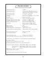
MANLEY
LABORATORIES, INC.
THE SNAPPER
OWNER'S MANUAL
TUBES
RULE
brought to you by the clever folks at:
MANLEY LABORATORIES, INC.
13880 MAGNOLIA AVE.
CHINO, CA. 91710 USA
TEL: (909) 627-4256
FAX: (909) 628-2482
email: [email protected]
website: www.manleylabs.com
CONTENTS
SECTION
PAGE
INTRODUCTION
3
MAINS CONNECTIONS
4
GETTING STARTED
5
MOVING RIGHT ALONG
6
LEARNING ABOUT TUBES
7
BIASING YOUR AMPLIFIERS
8
SIMPLE TROUBLESHOOTING
9
REPLACING A TUBE OR FUSE
10
TUBE FAQ
11
MORE SILLY VACUUM TUBE QUESTIONS
12
OPTIMIZING YOUR SOUND SYSTEM
13 & 14
CREDITS
15
SPECIFICATIONS
16
2
INTRODUCTION
THANK YOU!...
for choosing the Manley SNAPPER 100 watt monoblock amplifiers for your loudspeaker driving requirements. You
have possibly chosen this product because you auditioned it in a store or heard it at a hi-fi show and were impressed
with the sound. It may have been the right combination of price, power, features and styling for you. It may have
been because you know the Manley Labs reputation for quality, reliability, and integrity. If any or all of these were
the reasons, you made a good choice and for that, we thank you.
The MANLEY SNAPPER is designed to bring either unbalanced RCA-type line inputs or balanced XLR-3-type line
inputs up to speaker-driving levels in the simplest and most direct way possible. This is accomplished in only three
active stages through the judicious use of vacuum tubes, whose purpose-designed applications in audio amplification
are pressed to full advantage here.
The SNAPPER’s circuitry contains many subtle and overt refinements that promote uncolored and revealing musical
reproduction of the input signal. Of foremost significance is the all-balanced and self-balancing conveyance of the
musical signal as it travels through the amplifier, from input jacks up to and including the speaker terminals. This
approach aids in cancelling the undesirable interaction between the audio signals flowing through a given amplifier
stage and the power supply energy biasing that stage. One result of this approach is the rock-steady stabilization of
the input and driver stages, whose performance remains undisturbed regardless of signal dynamics or power supply
voltage fluctuations. Indeed, the two quantities here termed ‘power supply’ and ‘signal’ are locked into a nearly
perfect orthogonal isolation from one another, in spite of the fact that the signal is utterly dependent on the presence
of energy from the power supply, on which the signal rides. Put another way, the audio signal is restricted to
travelling in a west-to-east direction, while each stage’s power supply energy flow confined to a north-to-south
direction. This kind of isolation is very much the exception in other tube-based audio amplifier designs.
The SNAPPER’s 19-section output transformer is a brand new design from the Manley Magnetics department and is
really quite an amazing work of art. Ample 180 Joule energy storage in the high-tension power supply yields robust
musical body and athletic stamina. The Ultra-Linear output stage topology lowers output impedance presented to the
loudspeaker while boosting the amplifier’s tolerance of varying load impedance. Low levels of noise, distortion, and
negative feedback are partnered with the naturally high dynamic range of tube electronics which makes the Snapper
really jump to life.
Please read over this entertaining and enjoyable owner's manual carefully as it contains information essential to the
proper operation and maximum enjoyment of this instrument. Many of the remarks contained herein are especially
pertinent if the SNAPPER is to be your first long-term encounter with a vacuum tube power amplifier.
Thank you again, and please enjoy your new Snappers! (and the clever Owner's Manual.)
UNPACKING: Unpack the amplifiers carefully by removing all the custom foam packing material and make sure
that all supplied accessories are present. Carefully examine all items for any possibility of shipping damage. All of
the tubes are already installed and should have survived the journey protected by their very own foam insert. They
should be standing at attention in their sockets, and should show no signs of distress such as chipped glass, loose
internal components or obvious breakage. If the amplifier is damaged or fails to operate, notify the shipper or your
dealer or us or your local authorities immediately. Or if you suspect The Shipping People threw it off the airplane and
onto your front porch whilst flying overhead at 30,000 feet, notify the shipping company without delay and complain
to them as we only guarantee this unit to be able to survive a drop of 23,487 feet or less.
Your SNAPPERS were packed by Manny Q. with extreme love and each box includes the following components and
accessories:
a) 1 each, 6 foot IEC 3-conductor power cable (that you will probably replace with an expensive audiophile cord anyway.)
b) 1 each, Digital Multimeter (all the better to bias your amps with, my pretty!)
c) 1 each, Owner’s Manual per pair (that we hope you will keep reading...)
It is prudent to retain the shipping materials for future use, as they are custom-formed for the amplifier and
will greatly minimize the chance of shipping-related damage should you ever need to put your precious
Snappers in the careless hands of The Shipping People again.
3
MAINS CONNECTIONS
Your SNAPPERs have been factory set to the correct mains voltage for your country. (Well, that is what we
intended to do when we knew where they would be initially shipped.) The mains voltage that we built these
Snappers to operate with is marked on the serial badge, located on the rear of the chassis. Check that this complies
with what comes out of your wall.
There is no voltage changeover switch! The power transformer's primaries must be either wired in parallel for 120v
operation or in series for 230v or 240v countries so be sure to check the sticker and the serial number voltage
indication for proper mains voltage. Failure to properly comply with mains voltage requirements can cause
extensive damage to the system, which of course would not be covered by the warranty. If you relocate from, say,
a 120v country to a 240v country, you will need us to rewire the Snapper's power transformer for you or get
instructions from us to perform this operation if you happen to be as good at soldering as we are, or know someone
who is.
The mains fuse may be checked by first disconnecting the IEC mains cord from the power supply’s power inlet
plug. Then gently push the light grey fuseholder retainer clip located next to the IEC power socket. The fuse and
cap should spring outward toward your fingers. Inspect the mains fuse for the proper rating; change if necessary.
Refer to the fuse rating chart in the specifications section of this manual. If you do not know what a blown fuse
looks like, you may measure for continuity across the fuse ends. If your meter reads “OL” when you measure
across the fuse, that means “Open Leads” and that would mean the fuse is blown. A blown fuse usually indicates A
Very Bad Thing occurred. If this has happened to you, try to figure out why it may have happened. (Using a Fast
Blow fuse when we have specified a SLO-BLO fuse is one reason, output tubes running away into never-never
land are another reason.) If you have no idea why a fuse might have just blown on its own, you might want to
consult with Manley Labs or your dealer for further advice as Something Very Bad might have occured, like the
power transformer might have decided to retire early.
One way this could happen is by running the wrong mains voltage into the unit. Be sure not to do that.
If you live in a strange place...
Export units for certain markets have a moulded mains plug fitted to comply with local requirements. If your unit
does not have a plug fitted the coloured wires should be connected to the appropriate plug terminals in accordance
with the following code.
GREEN/YELLOW
BLUE
BROWN
EARTH terminal
NEUTRAL terminal
LIVE terminal
As the colours of the wires in the mains lead may not correspond with the coloured marking identifying the
terminals in your plug proceed as follows;
The wire which is coloured GREEN/YELLOW must be connected to the terminal in the plug which is marked by
the letter E or by the safety earth symbol or coloured GREEN or GREEN and YELLOW.
The wire which is coloured BLUE must be connected to the terminal in the plug which is marked by the letter N or
coloured BLACK.
The wire which is coloured BROWN must be connected to the terminal in the plug which is marked by the letter L
or coloured RED.
DO NOT CONNECT OR SWITCH ON THE MAINS SUPPLY UNTIL ALL OTHER
CONNECTIONS HAVE BEEN MADE. (...or else...)
4
GETTING STARTED
PREPARATION FOR INSTALLATION
Budget a suitable space in which to place the amplifiers and associated interconnect and mains power cables. This
space should be free of strong external magnetic and RF fields, and reasonably removed from strong loudspeakergenerated acoustical fields. This space should also be free of excessive heat or dust and large enough to permit easy
flow of cool air to the top, bottom and sides of the amps. Do not connect the SNAPPERS to the AC mains until the
other interconnections and items outlined below have been completed.
Keep other associated equipment some distance away from the amplifiers. This will help keep airflow unrestricted,
and cut down interference from radiated magnetic hum fields that can eminate from certain power supplies. Notice
that the output tube’s glass envelopes are capable of reaching high temperatures, depending on operating
circumstances. As with other equipment of this sort, it is best to keep the SNAPPER out of reach of pets or
children, or be careful to keep children and pets away from the amplifier when in use.
Before plugging in your interconnects, take a quick visual inspection of the tubes. Sometimes either through
shipping or unpacking things get jostled. Make sure all tubes are firmly in their sockets. You might also verify that
none have turned white inside. That indicates that air has leaked inside the tube (or the vacuum leaked out!).
Though it is rare, a tube is sometimes cracked or broken in shipping. It would need to be replaced before powering
up the unit. Give us a holler if this happens to you.
RCA AND XLR INPUTS
Choice of unbalanced [single-ended] RCA or balanced XLR input signal formats are made convenient by the use of
two discrete jacks at the rear of the amplifier. The amplifier does not invert the unbalanced input signal, and is
wired for the now more popular pin-2-high XLR convention. Pin 1 = Ground, Pin 2 = High(+), Pin 3 = Low(-)
An adjacent toggle switch facilitates choice of input signal format, permitting instantaneous selection of either the
RCA or XLR input. **NOTE** The following feature was removed in July of 2008. However, it is present on
units numbered up to and including MSN524: The balanced XLR input of these units also features an input
termination switch. When engaged, the termination switch lowers the balanced input impedance of the amplifier
from approximately 15Kohms to 600 ohms. Use of this resistive 600 ohm termination is only suggested when using
the SNAPPER with balanced signal sources whose output signals are transformer-coupled to the balanced line.
Proper line termination often helps in wheedling the best behavior from such sources.
Unbalanced input drive voltages of 750 millivolts RMS into the RCA jacks or 1.5V RMS into the XLR balanced
inputs will produce full output power.
SPEAKER CONNECTIONS
Never operate the amplifier without a speaker load, or suddenly disconnect the speaker
load while the amplifier is producing a signal. This risks punch-through of the enamel
insulation covering the transformer’s internal magnet wire. Permanent damage to the
output transformer may result and for that, you will be made to pay dearly, dear.
Never allow either speaker terminal signal to touch chassis or system ground. Treat each
speaker lead as a “hot” lead. Do not tie either speaker lead to a common switching or
loading point in your system. The negative speaker binding post is NOT ground!
So there you have it. The beautiful WBT binding posts fitted to the Snapper are for hooking up your speakers
cables. RED is positive and WHITE is negative. Get these to your speakers by way of nice speaker cabling
terminated with bare wire, bananas, or spades and do not ground out either lead. The WBT's feature a nice
slipping clutch action which will clamp down on your terminals without spinning them. No need to tighten them
like a gorilla or you might break something. Consider yourself well warned.
5
MOVING RIGHT ALONG...
NOW THAT YOU HAVE ALL YOUR CABLES PLUGGED IN, you may now connect the IEC power cord to the Snapper and to
an energized power outlet. (Unless you live in California and are in the middle of a Rolling Greyout®™.) Fire up all your upstream devices
first: sources, preamplifier, and such and allow them all to finish their turn-on cycles so your Snapper will not be amplifying any of
their waking-up noises.
Once they are stabilized, you may now switch ON your Snappers. The mains power switch is located on the back of the chassis right at
the IEC power inlet. You shouldn't need to turn the Snapper around or get yourself behind it. You should be able to "feel" the rocker
switch located next to the AC power cord. (We stuck the power switch way back there to keep the noisy mains furthest away from the
input circuitry.) Flip the switch away from the power cord to turn on the Snapper or towards the power cord to turn off the unit.
Your Snappers feature a SOFT-START system designed to smooth out electrical peaks and surges at power-up. Turning on the power
switch starts an approximately 30 second warm-up sequence that softly starts the amplifier. The control grids of the output tubes are
held at full negative bias until the input and driver stage wake-up transients have subsided. The badge lamps will blink during the
warm-up sequence, and the amp's inputs are held in mute condition to cut any signal drive until all stages are ready.
When the warm-up interval timer lapses, the badge lamps will revert to a steady state of illumination, and the input mute will be
released. Be careful not to hit the inputs with high-level line signals during the mute interval, or you may be blasted by sound when the
mute is released.
*Notice that the warm-up sequence will be re-asserted if the AC power is cut for more than a few seconds.*
Sometimes you might see a flash out of the little input tube's heater as it turns on. Tube heater filaments conduct a lot more current
when they're cold (room temperature), so they glow a little brighter when they're fist turned on, until they reach normal operating
temperature. Every incandescent light bulb tungsten filament does that too. That's normal so don't worry about it. I told you, you stop
worrying about it!
STOP WORRYING ABOUT EVERYTHING AND JUST GET LISTENING! Once audio is first heard from the Snappers, please
notice that it takes about 45 minutes of warm-up time for the system to reach thermal equilibrium. During this warm up time, go walk
your dog, make dinner, or play some lite pop music. Paul Anka would be a fun choice. Or even Tom Jones. Well, what you listen to is
up to you.
POWER DOWN (What? So soon?) (No silly, when you're done, unless you just wanna practice!) As a rule, power up your amplifiers
last, power down them first so they do not amplify any stray noises which could occur upstream from source components powering up
or down. Additionally, it is best to cut power to the Snapper when not in use rather then leaving the power on indefinitely. This will
enhance tube and system life. The tubes should last thousands of hours under normal conditions. Especially if you check your BIAS
every once in awhile. Keep reading to learn more about tubes and then on page 8 you can learn about biasing your Snappers.
WHAT'S HE DO? AND HOW? CIRCUIT FEATURES: The SNAPPER amplifier’s signal path features floating self-balancing
input and driver circuits, capable of handling unbalanced RCA, or higher level balanced XLR type signals. When presented with an
unbalanced source, the input stage is designed to produce a complimentary push-pull signal whose balance accuracy is within a few
percent of perfect. The following driver stage features the same self-balancing characteristic, at a higher power level. This results in
well-honed signal balance whose accuracy is independent of input signal symmetry, and limited only by the matching accuracy of the
driver [7044] tube’s total plate load.
Ordinarily, only a carefully matched inter-stage transformer would be capable of this level of balance, but that approach would
necessarily be burdened with comparatively severe bandwidth and phase limitations. Recent electronic component developments grant
options to us not available to previous generations of designers and permit economical and very noticeably laudable circuit
embellishments while maintaining sonic isolation from the signal path. The Ultra-Linear (sorry, we're not boasting: Ultra-Linear "UL"
is an output stage topology referring to how the screen grids are hooked up to the special UL taps on the output tranny's primaries)
output stage properties include an output transformer whose secondary winding is balanced, with grounded center-tap. The signal
appears at the two outside taps of the output transformer, which are made available at the two speaker-output binding posts. Balanced
global negative feedback signals are sampled from these outputs, and are routed back to the input stage. The entire circuit, including the
output transformer and some loudspeaker back-EMF, is thus included in the feedback loop(s) all 9dB's of it, which ain't that much
actually compared to some amplifiers we could mention.
TUBE TAWK: As with all tubes, certain parameters degrade with age. This is due to decreasing cathode emission, a natural process
found in all tubes. There are just so many electrons on that cathode and one day, they will have all jumped off. An excessive increase in
noise level or very unstable output tube bias can indicate the need to replace a tube. The electrolytic capacitors will probably eventually
dry out or start leaking and need to be replaced. Maybe in 15 to 20 or 30 years you will need to do this but don't worry about this for
now... didn't I tell you to stop worrying? But I do worry: How long will these tubes last? We can’t say for sure. Nowadays, as in
years past, bad tubes do emerge from the manufacturer’s assembly lines. Some small signal and power output tubes die prematurely
while others, especially small ones like the 12AX7, AU, AT and so on can last for more than 30 years of continuous use! The chief
determinants of tube life expectancy are the stringency of the particular application, and the initial build quality of the tube itself. The
average for the tubes in the SNAPPER should to be around 2000+ hours for the output tubes, hey, maybe lots more, depending on
usage, more for the input and driver tubes. We've seen 60,000+ hours on a set of tubes, but we're not trying to get your hopes up as it is
better for the life on your tubes to exceed what we tell you they will do so you will feel better when they do and be all surprised.
6
More Tube Tawk (while we’re at it)...
How can I tell when I need to replace them? Most problems
relating to the output tubes will show up while performing the
bias procedure (on the next page). Tubes that cannot be
adjusted within the specified range or have a very unstable
reading are should be replaced. If the tube s plate (the grey
metal rectangular box-like part most visible from the outside)
is glowing cherry red or orange, then the tube is severely
overheated. Check its bias immediately; if unable to adjust,
then turn off the amplifier right away and replace the tube.
The input and driver tubes can become noisy (hiss) or the
amplifier may exhibit audible distortion; substituting known
good tubes is the best way find the bad one. You got 2
channels to play with! They all can’t be bad at once.
All tubes are microphonic to some extent; that is, they will
make ringing noises through the speakers when tapped or
vibrated. Here again, substitution will determine which one is
overly sensitive to mechanical vibration. Obviously, any tube
that is totally dark inside while powered up or is cold to the
touch (careful!) is defective, or not making good contact with
the heater contacts in the tube socket.
Most tubes have a silvery coating deposited on some area
inside the glass bottle. This coating is put there by the getter ,
and its job is to soak up or get contaminants, such as air
molecules left over inside the glass envelope during the tube s
manufacture, and help keep the vacuum hard. If the getter
material has turned white (compare to another tube), then the
tube has lost vacuum (or gained air!) and is definitely bad.
Replace at once. Don t turn the amp on. Throw the tube out.
Do I need to replace them all at once?
No, at least not with these amps, or unless all the tubes have
clocked some thousands of hours of use. Some tube amps do
require that if one tube has to be replaced that a complete
matched set put in. All Manley amps use individual bias trims
for each output tube which allows a single tube to be replaced.
Absolute best performance is achieved when the tubes are
most similar, both in bias requirements and transconductance
characteristics. We batch them and label each tube so that in
the event of a replacement you can get one from Manley of
similar characteristics as the others in your amp. We need that
hand written number on the top of the tube (Output tubes only.
We know what we need to give ya for input or driver tubes).
Does the sound of the amp change as the tube ages?
Yes, but not too much, and even then, given good tubes, it is
fairly strongly related to the amp design. The tubes can be
allowed to reach their technical life limit, or they may be
replaced more frequently depending on the listener s taste
and accompanying equipment. In general, the band edges will
suffer first, with very gradual loss of the deepest bass and
ultrasonic treble. The SNAPPER is designed to meet stated
power bandwidth specifications at 80% of rated output power
at the end of useful tube service life.
7
By way of contrary tube application contrasts, it is not like
big guitar amps where tubes are replaced every 6 months for
reasons of tone . The SNAPPER s tubes are arranged to
operate in a quite conservative operating regime, allowing a
very long life and less change between old and new tubes.
This is where that figure of 2000 hours, or 4 to 5 years of use
comes from. You may notice an improvement between tubes
this old and new tubes depending on how critical you are.
Keep in mind the sound of new tubes changes most in the first
weeks of use before they can be considered broken in . At
first they may sound a little tight and direct (like some
people we know).
Is it difficult to replace a tube? Yes, but only if you have
trouble replacing light bulbs. It is super easy. Turn off the
power. Just let the amp cool a few minutes so that you don t
burn your pinkies. It helps to wiggle the tube gently rather
than pulling it out straight. Use some terry cloth material or
an oven mitt if time is pressing.
Even if you don t consider yourself technical you probably
have more technical ability than your parents and they used
to fix the family TV set by taking out the tubes and putting
them through the tube tester at the local pharmacy. It is
almost as easy to re-insert a tube. Just make sure it is correctly
lined up with the socket and you don t bend a pin. Notice that
the 9-pin miniature tubes have a gapped set of pins, making
a rotational installment error nearly impossible. The larger
8-pin or octal-based tubes have no gap in their pin sets, but
instead have a larger keyed center pin formed from the inert
plastic plug material. The key makes insertion of the tube into
the socket nearly impossible unless the key lines up with the
matching hole in the amp s octal socket. Notice that octal
tubes which have damaged or missing keyed center pins
should NOT be used, since some output tubes internal wiring
can cause dramatic equipment failure by short-circuit if
incorrectly fitted to the amp s sockets.
You can wiggle the tube when reinserting too. If you had a
solid state amp (heaven forbid!), transistor replacement
would merely be chapter 1 in the saga. You would have to
open it up, diagnose the bad transistors and burnt resistors,
de-solder ’em, find replacements (good luck on locating
those germanium beasties) re-solder ’em, and hold your
breath as you turn it on. Best have your Platinum credit card
handy for ordering more. Or you could send it back, be
without music for a few weeks, pay for service by the hour
and be ready to administer nitroglycerine tablets under the
tongue when it fries again.
That’s why TUBES RULE: If you need a tube, or set of
tubes, Manley Labs will be happy to sell you matched sets at
a good price. And if you prefer to send the unit back for repair
or adjustment, our warranty covers most everything except
tubes (6 months only please) and abuse (7 months only-- just
kidding). Plus we handle ground shipping back to you
(unless you live overseas, cuz there’s no ground service!)
Repairs usually take less than a week. Could we do more?
(That’s a rhetorical question. It’s late. Just keep reading...)
BIASING YOUR AMPLIFIERS
DON’T WORRY IT IS SUPER-EASY!
Convenient test points for checking the standing current of each EL34 output tube is available on the top of the
chassis, near the output tubes. The test points are connected to each tube s 10-ohm cathode resistor.
Tube bias is a frequent source of confusion and misinformation, especially as it pertains to output tubes. This is
partially due to the practice of using the term bias for many situations throughout the electronics industry in
general, along with the nature of the requirements needed to provide a proper electrical environment in which to
efficiently operate a given audio output tube. Here, therefore, is a concise (oh really, Mitch?) picture of what is
going on in the EL34 output tubes when the bias control is adjusted
When the amplifier power is switched on, several voltages are quickly developed by the amplifier power supply.
Around +575 volts DC for the plate, and about —75 volts DC, low current and low power, for the control grids. Six
and 12 volts are also applied to the appropriate tube filaments. All of these voltages are referred to the output tube
cathode voltage, which is usually within a few volts of circuit ground or chassis potential
The heater (orange glowing filament) of the tube inside the cathode sleeve rises to about 1200 degrees C. This heats
the special oxide coated nickel cathode sleeve and, after 10 or 20 seconds, the oxide produces a generous cloud of
electrons, which are negatively charged. The electrons are strongly attracted to the large positive plate, which is
beckoning them from across the vacuum with an irresistible +575 volt potential. Notice here that, as usual, the
differing charges, plus-to- minus, attract, and like charges plus-to-plus or minus-to-minus repel. Without some
control, the tube is in danger of running at full cathode current, which due to prodigious input power from the 575V
power supply, would lead to red-hot plates and quick tube destruction. Now the control grid is used to throttle back
this hazardous situation, by the careful application of a negative voltage to the control grid. This applied negative
grid voltage, Mr. Bias, retards the flow of electrons from the cathode to the plate by repelling the cloud of electrons
around the cathode with a like charge, minus-to-minus, and confining most (or all) of them to the space between the
cathode and control grid. Much like a Venetian window blind is used to control sunlight entering a room.
When you adjust the bias control, the control grid is being made slightly less or slightly more negative. How
much this electronic venetian blind has been opened or closed may be observed by watching the cathode current
with a voltmeter at the tube s test point. The higher the current, the more open the blind or valve setting, hence the
higher the voltmeter reading. Notice that contaminants in the vacuum and other factors can sometimes conspire to
reduce or eliminate the effects of the negative voltage impressed on the control grid, which can lead to runaway
over-current conditions and ultimate tube failure.
OK, Mitch, that’s enough for now. My eyes are glazing over. HOW DO I CHECK THE BIAS?
Checking the standing current may be performed by connecting a DC millivolt meter between a test point and
chassis ground, with the positive red meter lead to the test point, amplifier on, and zero audio signal present. Just
leaving your preamplifier turned off is not not a bad idea. Adjust the corresponding bias trim control until a meter
reading of 300 millivolts is attained. This corresponds to 30 milliamps of standing current because Ohm’s Law tells
us that 0.300VDC divided by 10 ohms (the cathode resistor) equals 30mA. Changing the standing current through
one output tube may slightly alter the amount of current flowing through the neighboring tubes. Therefore, check
the remaining output tubes and readjust as necessary. Turn off the amplifier and replace any tube that cannot be
brought to the correct standing current when varying its bias adjustment control. Do not let the standing current
exceed 50 milliamps (500 millivolts) except briefly as necessary during the adjustment procedure or you might be in
for a surprise. (And we’re not going to tell you what that surprise might be or it will spoil it for everybody.)
You should expect extended life from the tubes in your MANLEY SNAPPER amplifiers if you adhere to the
procedures described above, and check your EL34 standing current at least once every 2-3 months. Generally, the
longer the tubes operate, the less they should need standing current level inspection. And when that sad day comes,
and the tubes have reached their lifetime service limits, be of good cheer, for should you ever need replacements we
stock all the tubes used in these amplifiers, pre-screened and tested, and at very reasonable prices too!
8
TROUBLESHOOTING
Here are some suggestions to try out in the event you encounter some of the symptoms below.
If you encounter some other symptoms, then maybe you have some other problems that we don’t know about.
HUM: Forgot the words. Try a mains ground adapter if they are legal in your country. They are
also called 3 pin to 2 pin adapters or cheaters and are available in hardware stores. There should
be one ground in your system and only one. If two or more pieces of gear have 3 pin AC mains
cables, and they are grounded into the wall, a ground loop can occur which will usually cause hum.
Either the preamplifier OR the power amps, when sharing an earth connection, are probably the
best ground reference for your system, but not both or all of them.
HISS: Stray snakes in the room. Switch to the unused input using the RCA / XLR selector. Did the
hiss stop? If so, then the source of the hiss is something upstream from the SNAPPER. If the noise
level is the same, then the problem is in the SNAPPER - probably a noisey 12AT7 or 7044. Try
swapping (with the power off please) one tube at a time across to the other channel to see if the hiss
moves over there. If it did, then you found the troublemaker and you can contact us and we will
report him to the proper authorities and send you a tube. And maybe sell you some spares for next time.
OUT O’ BALANCE: Mom told you not to put anything smaller than your elbow in your ear. The
two speakers sound different. It may be the CD or source and the way it was recorded. First try a
different source, or switch the source to the mono mode if possible, and listen for any level shifts.
Notice that each SNAPPER s overall gain is carefully set at the factory, and should be within 0.25
dB (or better) of each other. Next try swapping the inputs. Power down and swap left and right
inputs. If it is the source, then the problem will follow the swap. Return them to normal (L=L).
Power down again and next try swapping the speaker connections by putting the left speaker wire
in the right terminals and right wires into the left terminals. If the problem switched sides then one
SNAPPER is suspect; if the problem stayed on the same side it is probably a damaged or fatigued
speaker or some crossover switch that got changed by the cleaning lady.
NO SOUND, NO PILOT LIGHT, TUBES DARK: Did you pay your Edison bill? Check the
Snapper’s AC Mains fuse. Check AC power cord. Is the amp plugged into a working electrical
outlet? (This has happened to everyone at least once!).
NO SOUND, PILOT LIGHT ON, TUBES LIT: Forgot to lower needle onto record. Check
speaker connection, input selector switch and input connection (exchange with the other channel).
Take a bias measurement. Do all bias test points read zero volts? If so, the B+ fuse is blown.
CAREFULLY INSPECT ALL OUTPUT TUBES BEFORE REPLACING THE B+ FUSE because
you probably blew one. That B+ FUSE info is on the next page, page 10. (See also Replacing
Tubes on page 7 if you forgot already what a blown tube might look like).
ONE OUTPUT TUBE WILL NOT BIAS: It doesn’t want to. Try to will it to comply. If the bias
voltage one of the tubes will not adjust at all or reads zero volts, and the tube filament is lit, try
replacing replace that particular tube. If the reading still is way off or reads zero, turn the amplifier
off. Set your multi-meter to ohms (the Omega sign) instead of DC volts (NOT the wavey line,
that’s AC volts!). Now measure the bias test point resistance (that’s what Ohms do) between the test
point and the ground test point. It should read approximately 10 ohms. If it reads very high or not at
all, then the 10-ohm cathode resistor connected to the tube has become hurt by that tube not being
nice to it. One function of this resistor is to act as the final safety valve in case of a shorted (not
nice) output tube, preventing damage to the rest of the amplifier should a short occur. Replacing
this resistor can be done by anyone with adequate soldering skills. We recommend contacting our
service department here at the factory for specific instructions on how to do that because we are
only giving you enough information in this owner’s manual to almost be dangerous.
9
REPLACING a FUSE or a TUBE:
Yes there are user-servicable parts inside! (Contrary to what The Safety Regulatory People tell us to
declare on the rear of the chassis.) But, as with other vacuum tube based products, there is also high
voltage present. Therefore caution must be used when covers are removed; otherwise there could be
shock hazard. Probably not enough to kill you, only enough to severely annoy you should you
inadvertently grab onto the B+ volts. As with all mains-powered gear make sure the mains power is
off and mains cord is unplugged. If the amp has been powered up within the last 15 minutes stop! and
let the large electrolytic capacitors discharge otherwise you could still get a shock even though the
unit is unplugged. Really! You will need a #1 Philips screwdriver to remove the bottom cover screws.
MAINS FUSE: See page 3.
B+ FUSE: If all of the sardine none of the tubes show any bias reading at all, and the lights are on,
and no tunes will play, you might have popped a B+ fuse. This fuse is here to protect the output
transformer from a rougue tube or some other strange event. Before replacing it, stop and think a
minute if you noticed anything, like a bang or crack noise coming from the speaker. Or maybe you
notice one of the tubes looks cracked or sick. Or maybe you smelled something funny? And saw a
tube take off and glow bright red or orange? Any of these events could be a tube "running away". If
you are aware of what went down and can clearly see the offending tube, then yes, do replace it and
then replace this B+ fuse. Always check the bias on a new tube as the amplifier warms up and watch
him closely like a new puppy to make sure he behaves for the next little while. The fuse is a1/2 Amp,
250v MDA SLO-BLO (time delay). The size is 1/4" x 1 1/4". Only use a ceramic fuse here as the
glass ones sometimes flame out or crack. Do not use a Fast Blow fuse or you will be replacing them
on every downbeat. And remember those 575 volts we mentioned? They are living here on this fuse,
so you had better MAKE SURE THE AMPLIFIER IS OFF AND UNPLUGGED AND
DISCHARGED before you dig in here! Use one hand only when reaching into the enclosure or
touching any components inside. Keep the other hand away from the amplifier, preferably in your
pocket. For real!
SWAPPING TUBES: Three tube types that are electrically and plug-socket compatible with the
12AT7A dual triode include the 6021, 6679, and the ECC81. There is no direct replacement for the
7044 dual triode, although the 6900 or 5687 are pin-compatible substitues. We have no experience
with either of those two types and thus cannot vouch for their worthiness in the Snappers. The 7044 is
really the best choice here, trust us. Actually think long and hard before just trying to score some
golden lovely tubes on ebay for $125 each. Are they really what they claim to be? (Paint can be
scraped off or applied at will.) Are they really new? (Hard to tell sometimes.) Are they tested? Were
they tested for optimum performance in a Snapper? We didn't think so. By virtue of our experience,
testing, and selection we do recommend you obtain replacement tubes from the factory. We will
indeed be looking after the best interests of you and your Snapper in our tube selection travails.
Please direct any other more involved questions regarding the guts of the Snapper to
MANLEY LABS Tech Support for further assistance.
Taking advantage of the amazing technology of email:
[email protected]
...is the best way to reach us, because we might be eating lunch or something.
10
TUBE FAQ
A few general all-too-frequently-asked vacuum tube questions from the
manleylabs.com FAQ as found on our website are answered here in case you don't
have internet access (which we don't doubt because after all you bought vacuum
tube amplifiers, didn't you?):
(Don't take that comment personally. EveAnna still drives air-cooled Volkswagons... We're not perfect either.)
FAQ #16. Do you sell tubes?
I don’t know what you’re talking about.
FAQ #16a. I need to retube my Manley amplifier. Do you sell tubes?
Sorry. Just kidding. Yes, of course we do. We have about 100,000 tubes in stock of the several major
types we use.
FAQ #16b. Why should I buy tubes from you?
We are only as good as our worst tube. We are very selective about which tubes we use in Manley
products and we have several different testing and burn-in jigs to test for certain parameters which will
be most important for that tube in a given circuit. We will test and select a tube set for you that will be
optimized for your Manley piece of gear and in most cases, your tube set will actually be tested in
another one of what you have.
FAQ #16c. Are tubes expensive?
Not especially. Although I might have made a killing in the stock market had I invested the money I
instead put into finding and stocking these large quantities of tubes ten years ago when the USA military
were dumping their stocks of NOS JAN vacuum tubes. Seriously, there is the stocking cost to consider in
the cost we must charge, development charge of the computerized test jigs we built, then more
importantly the time it takes one of our guys to run a little tube through its qualification procedures.
Remember, a given tube cannot be improved during testing. It is the way it is, and one hopes it stays that
way. It can only be selected, and in selecting that tube that will work really well for your piece of gear,
we probably had to throw away several. In some cases we might have had to go through 30 tubes to find
the quietest one, or the one with the lowest microphonics, or the one with the best internal matching,
depending on what parameters are important for that circuit. That is all factored into the cost somewhat,
but no, overall, we don’t charge enough for replacement tubes.
FAQ #16d. NOS? JAN? What does that mean?
New Old Stock. Joint Army Navy. Yes our military used to use vacuum tubes. As long as the glass
doesn’t break, tubes are impervious to a nuclear explosion’s electromagnetic pulse unlike little silicon
devices whose little junctions would go poof!
FAQ #16e. Good to know. How long do tubes last?
Some of them are dead out of the box. Some tubes don’t make it through burn-in and after a few days
they just go noisy or quit. Sometimes UPS sabotages our shipments and after all our testing efforts the
tube arrives broken at your place. Sometimes a tube decides to end it all early and intentionally
misbehaves after a few months. Other tubes are real troopers (like my 98 year old neighbor) and run
strong for 30 years. We have documented cases of power tubes in Manley amplifiers going over 60,000
hours non-stop in recording studios 24/7/365 without a re-tube. In one case in particular, the amplifiers
were never turned off and had their own dedicated air conditioning for the amplifier rack they lived in.
This certainly contributed to their long life.
11
More silly vacuum tube questions...
FAQ #16f. Should I turn off my gear between uses?
While power cycling is a factor for ultimate tube life, there also is a fixed number of electrons that can ultimately
jump off the cathode. In general we do recommend if you aren’t using the gear for more than a few hours you
should power it down. Do you leave the lights on in your house when you are away?
FAQ #16g. But it sounds different when you first turn it back on. What is the warm-up time for this gear?
I generally recommend 45 minutes warm-up time for everything to reach operating temperatures and sound like it’s
supposed to.
FAQ #16h. What about break-in time for new gear?
We burn in the gear for a couple of days before it is shipped out. Folks report that after about a week of break-in
that it sounds better. Some of the more fussy people of course report that full break-in takes much longer....
FAQ #16i. How do I know a tube is broken?
All the vacuum has leaked out.
FAQ #16i.i After the vacuum leaks out, where does it go? Is there some way to
collect it and put it in another tube, to make it last longer?
You have to suck really hard.
FAQ #16j. No really, how do I know a tube is broken?
Usually a tube whose glass has been broken or cracked usually will have a white powdery like substance inside it
where all that silvery stuff used to be. No, it is not cocaine and we didn’t put it there..
FAQ #16k. Does the glass explode?
I haven’t seen it happen. Usually the glass will just crack at the base of the tube if it is going to physically break due
to a sudden change in temperature and “all the vacuum will leak out”.
FAQ #16l. Other than outright failure of a tube, how do I know when it is time to re-tube?
Generally speaking, for the small tubes, if you notice an unacceptable increase in background noise (“hiss”) then the
tube who is responsible for making the gain in the circuit probably needs to be replaced. The tube(s) making the
gain will usually be shorter than the output tube. Common types we use for gain in most of our circuits will be
12AT7, 6201, 12AU7, 5814, 12AX7, 5751, or 6072. The output buffer tube in most of our line-level circuits will be
either the 7044, 6414, or 12BH7. These tubes usually don’t cause too much trouble and either work or don’t work.
Turn the lights off and see if you see the little tubes glowing. Look for one that looks like it has cocaine in it.
For the power tubes in our amplifiers, after a few years if you notice a small revolt going on where several of the
output tubes are misbehaving or getting hard to bias, you might consider doing a full re-tube. Keep the old ones that
did not join the revolution as emergency spares.
FAQ #16m. Can I change a tube myself?
R.T.F.M.
Do you call in specialists to change your light bulbs for you?
12
Optimising Your Sound System
This section is full of Hutch's little hints that may help you get the most out of your stereo - and it may not
cost anything or cost very little. Probably, you know most of this, but hopefully some of it may be new or
refresh your memory or just be refreshing reading in a manual.
A very important factor is your speakers. Hopefully you have good speakers and they are appropriate for your
power amplifier. What is appropriate? Well, with 50 watt of tube power per side and probably a limited
budget we would hope for reasonably efficient speakers so that the system will get loud enough for the music
you listen to. The "spec" to look for is "sensitivity" or "efficiency". A speaker that is 95 dB efficient will
easily get as loud with 50 watts as 85 db speakers with 150 watts. "85" will do if you only listen to folk or
chamber music. Usually you pay about the same for high sensitivity speakers but in amplifiers more watts is
more $. By the way, many reviewers confirm that 50 tube watts is similar to 100 solid state watts. If you are
buying speakers, it is wisest to carefully listen to them before buying. You will most likely like them longer if
they tend to sound natural and real rather than over-emphasized in some area. In other words, think "accurate
reproduction" not "numbers" and "hype".
The price of speakers is often directly related to the low frequency response. Great lows generally require
deep pockets and plenty of power. Thanks to "home theatre" there are a lot of powered subwoofers available
that won't drain your resources. Get one that connects to speaker outputs so that it follows your input selection
and volume control. This makes connecting them pretty easy.
There are some very interesting speaker tricks. Most people just place them wherever it is convenient. Spouse
approval is a real factor. We suggest that you experiment with speaker placement, then when they sound
100% better you bring in the spouse and demonstrate the difference. They should be able to hear the
improvement and may totally agree with your choice. You should aim for equal distances between your
listening position to each speaker and from speaker to speaker. The ideal is an "equilateral triangle". Try to
get the speakers off the floor, and away from the walls (both side and back). The angle of the tweeter or
speaker front panel to your face is also critical and experiment with that too. You should be getting a smooth
frequency response so that highs and lows are balanced and mids not too prominent or distant. It should
simply sound "natural". When we buy color TVs the first thing most of us relate to is flesh tones because it is
something we all relate to and know when they are right. The equivalent thing in audio is vocal tone. We have
evolved amazing discrimination for the varieties of human voice and much less for other instruments. Use a
few well recorded CDs with vocals and adjust the speakers to get the most natural voices. If you are lucky,
you will end up with a system that creates a 3D picture of the music that not only has left/right width but a
solid distinct center. It should also make some sounds seem in front of the speakers and some behind. We
have heard some systems with our amplifiers even give an illusion of the height of the individual musicians.
Most rooms are longer in one dimension. Some systems sound best with the speakers across the short
dimension and the listening position part way back but not right at the back wall. Some systems are better
across the long dimension. The only way to find out is to try.
If you are getting this amazing imaging and soundstage, you may be interested why you have it if you have a
nice vacuum tube amplifier. These are very audible effects that seem to be beyond normal measurement
technique or textbook electronic theory. This effect is directly related to the amount of negative feedback used
in a design. The less feedback the greater the imaging. In transistor amplifiers it has been common practice to
use more than 80 dB of negative feedback. Conventional designs need it because transistors are not
particularly linear devices and it forces the circuit to get low distortion figures as well as very high damping
factors. Tubes are much more linear and inherently low distortion. Tube amplifier designs use far less
negative feedback (less than 20 dB) as a result . We speculate that the negative feedback may have a negative
effect on transient accuracy. It is reasonably documented that the feedback does reduce the lower order
harmonics in distortion but can raise higher order harmonics that are more audible. Feedback also makes the
transition from clean to clipping very abrupt and abundant with high order harmonics. The best audio devices
always seem to be simple & aesthetically balanced, with form following function.
13
More Helpful Hints from Hutch...
You may have bought a great system but there is a good chance that you are only getting a fraction of its
potential. Very frequently we have experienced top quality electronics sounding unimpressive simply
because acoustics were ignored. Even amongst studio engineers, few can really tell the difference between
good speakers in a bad room and bad speakers in a good room - but they all know good speakers in a good
room and very likely so do you. Acoustic techniques are better explained in books on recording studio
construction. You can buy good ready-made acoustical materials and/or build them yourself for a fraction of
the cost. Dollar for dollar, you can expect far greater improvement with acoustic treatment than expensive
interconnects.
Most people think acoustics is about sound-proofing but there is a lot of info available for improving the
reproduction of music. Sound-proofing is usually expensive. Luckily just improving the acoustics in a room
can be pretty painless. You may be able to change or move what is on the floors and walls (without getting
expensive or ugly). The improvements may be dramatic.
Number One on the bad list is parallel surfaces. That pretty much includes most rooms. Parallel surfaces can
support a very short echo that is known as a standing wave. It boosts some frequencies and cuts others. This
effect is often called comb filtering because of the multitude of peaks and dips. One cure is breaking up the
big surfaces with a variety of smaller ones. The good news is that book shelves, curtains, wall hangings or
macrame, plants, furniture and lamps all help. Not only does this balance live surfaces with dead ones but
"checker-boarded" areas also act as a sort of diffuser. You can probably build low cost effective and
attractive diffusers or have them made if you want something better (and more efficient).
Number Two is very unbalanced room treatment. Both too "live" and too "dead" is generally bad. One might
think that wall to wall carpets & curtains is going to be fine, but watch out. All that stuff only eats highs and
a little mids, but doesn't do anything to the lows. The lows end up very live in contrast to very dead highs.
One way to balance this is get some thick absorbsion into the corners. Thick absorbsion in the corners is
most effective to lows. The idea is to balance high and low absorbsion. Even normal speech sounds weird in
near empty rooms with plain painted gypsum walls and hardwood floors. The simpler the decor the more
intense the acoustic problems. The only hints we can offer is that the wall behind the speakers and behind
you are often the most important. You can build some simple absorbers. Simply cut two 4'X8' pieces of 2"
rigid fiberglass or open cell foam rubber into 16"X8' strips and wrap some white cloth around them. Easy,
clean looking and cheap. Experiment, lean them against the wall at various places. Even very experienced
acoustic designers experiment, listen then decide rather than attempting to predict every result. A variation
is to use "perf-board" as a backing if you intend to stretch the fabric reasonably tight. It may also help with
hanging the strips to the walls. Perfboard with a one or two inch space behind it is an alternative front
surface to increase diffusion or can do double duty as a simple helmholtz absorber (for the low mids) and
can be effective on the ceiling. You can hang a few up there either flush or dropped a few feet if you have
the height to absorb lower frequencies. The wall behind the listening position is usually responsible for too
much or too little lows compared with the rest of the room. Read up on slat and membrane absorbers for
problems there - the panels described above won't help much for that.
Number Three is lack of left/right symetry. In order to get the left and right similar sounding and getting a
rock-solid center you should have identical left and right walls and distances. The ideal is a perfectly
symetrical room but this may not be practical. Again, try to achieve this with positioning.
Some of the "test" CDs have a variety of low frequency tones or sweeps. Use them to find rattles and buzzes
in the room. Lamps and fixtures, some cabinets and components can do this. A little tape or glue can often
fix these types of things. If you are getting serious about this kind of thing you can get a variety of test gear
from measurement mics to real time analysers or computer software. These are useful tools but do not
depend on the readings unless you are very experienced using them. Best to use your ears and use the test
gear to verify what you hear and to document the changes. Remember that test gear neither makes records
nor listens to music. Frequency measurement often ignores "time" and exagerates some factors and glosses
over others. Steady tones are virtually useless in real rooms. The more comprehensive tests give complex
data that needs to be correctly interpreted to be useful. Use 'em but don't jump to confusions. Always use
ears too. Ears are fabulous instruments.
14
CREDITS
MANLEY SNAPPER
An EveAnna Manley Production
Starring:
Mitch Margolis as the circuit designer
Mastered by: Baltazar Hernandez
In keeping with our new tradition of naming fresh new Manley HIFI products after
aquatic creatures, we set out to design a very nifty 100 watt monoblock.
From Mitch's creative brain issued forth all the clever circuitry and schematic design.
Mitch worked closely with Joe Rodriguez in the Manley Magnetics department for two
months and through 19 prototypes to refine the quite interesting 19-section output
transformer that resulted from plenty of studied calculations, laborious winding and
lamming, and intensive batteries of tests both on the bench and in our listening environs.
All the tunes must pass through this iron beast before reaching the final speaker
destination and so it was an important thing to do right.
Balta did all the circuit board and metal work drawings and assembled the prototypes.
Humberto and Martin measured and aligned everything as Quality Control Technicians
are prone to do.
You can blame this silly manual on EveAnna and Mitch with some intelligent ramblings
contributed by Hutch. Chris added some not-quite-as-intelligent stuff later too. There
are no pretty pictures in this manual because everything is so clearly labelled on the
chassis and that epoxy paint Elias uses on the silk-screen is nearly impossible to get off
and so we didn't think you would mind having to just look directly at the amplifiers to
understand what we are talking about in these pages.
All the strange and extraneous remarks you have noticed so far in this Owner's Manual
have been put here on purpose because we know you will keep reading so you don't miss
the next quip. In the rare case that you find a mispelling or an error in grammer in this
Owner's Manuel, please consider that it was put there for a porpoise as their are all ways
sum peeple looking four missteaks and they mite as well fined them hear.
15
SPECIFICATIONS
Input Impedance RCA:
Input Impedance XLR:
Dynamic Range:
THD+noise @ 1W
Frequency Response at 110W full power:
Frequency Response at 5W into 5 ohms:
475 Kohm
15 Kohm (serial #MSN524 and below are
switchable between 15 Kohm or 600 ohm)
750mV input = 110W output
1.5 V input = 110W output
factory set for 31 dB; Range = 29.5 to 34.5dB
factory set for 25 dB
factory set for 9dB of global NFB
110 Watts (1.5% THD @ 1kHz)
100 Watts (1.5% THD @ 1kHz)
Typically 90 dB A-WGT 20-20K
Typically 105µV = -77dBu A-WGT
Typically 388µV = -66dBu unweighted
98dB
less than 0.1%
15 Hz to 40 kHz FLAT
10 Hz to 65 kHz FLAT, -3dB @ 100KHz
Recommended Speaker Load:
Actual Output Impedance:
Optimized for 5 ohms
1.5 ohms
Input Sensitivity RCA:
Input Sensitivity XLR:
Gain RCA:
Gain XLR:
Negative Feedback:
Maximum Output Power into 5 ohms:
Maximum Output Power into 8 ohms:
Signal to Noise Ratio Ref. 1W:
Noise Floor:
Power Consumption (idle):
170 Watts (1.4A @120VAC)
Power Consumption (at Full Power 110W): 336 Watts (2.8A @120VAC)
Vacuum Tubes: 1 x 12AT7WA Ei, 1 x 7044 GE JAN NOS, 4 x EL34EH Output
B+ Voltage: 570V DC
Output Tube Quiescent Standing Current: 30mA
Set Bias for 300mVDC measured across 10 ohm cathode resistor
Fuse types for 120VAC operation: MDL or MDA 4 AMP / 250 Volt SLO-BLO
240VAC operation: MDL or MDA 2 AMP/ 250 Volt SLO-BLO
B+ FUSE:
MDA 1/2 AMP, Ceramic 250 Volt SLO-BLO
Dimensions: 15" deep x 13" wide x 8.75" tall
Shipping weight each: 45 pounds
Specifications subject to change because they just might.
16